TS129 Small EG Connections Technical Requirements - Capacity not exceeding 30kVA
TS129 Small EG Connections Technical Requirements - Capacity not exceeding 30kVA Issued – 06 July 2021 The use of this document is subject to the conditions stated in SA Power Networks’ disclaimer at the front of this document.
Small EG Connections Technical Requirements - Capacity not exceeding 30kVA Published: 06 July 2021
TS129 Small EG Connections Technical Requirements - Capacity not exceeding 30kVA
TS129 Small EG Connections Technical Requirements - Capacity not exceeding 30kVA Issued – 06 July 2021 The use of this document is subject to the conditions stated in SA Power Networks’ disclaimer at the front of this document.
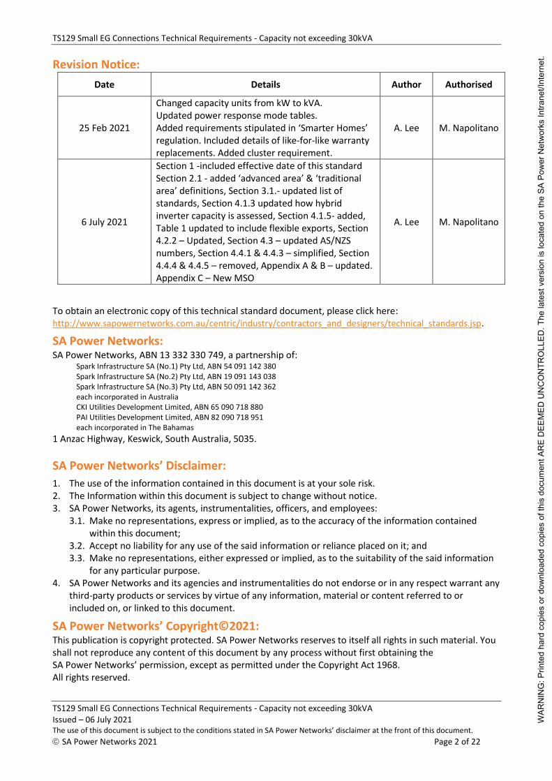
Changed capacity units from kW to kVA. Updated power response mode tables. Added requirements stipulated in ‘Smarter Homes’ regulation. Included details of like-for-like warranty replacements. Added cluster requirement.
A. Lee M. Napolitano
6 July 2021
Section 1 -included effective date of this standard Section 2.1 - added ‘advanced area’ & ‘traditional area’ definitions, Section 3.1.- updated list of standards, Section 4.1.3 updated how hybrid inverter capacity is assessed, Section 4.1.5- added, Table 1 updated to include flexible exports, Section 4.2.2 – Updated, Section 4.3 – updated AS/NZS numbers, Section 4.4.1 & 4.4.3 – simplified, Section 4.4.4 & 4.4.5 – removed, Appendix A & B – updated. Appendix C – New MSO
A. Lee M. Napolitano
To obtain an electronic copy of this technical standard document, please click here: http://www.sapowernetworks.com.au/centric/industry/contractors_and_designers/technical_standards.jsp.
SA Power Networks: SA Power Networks, ABN 13 332 330 749, a partnership of:
Spark Infrastructure SA (No.1) Pty Ltd, ABN 54 091 142 380 Spark Infrastructure SA (No.2) Pty Ltd, ABN 19 091 143 038 Spark Infrastructure SA (No.3) Pty Ltd, ABN 50 091 142 362 each incorporated in Australia CKI Utilities Development Limited, ABN 65 090 718 880 PAI Utilities Development Limited, ABN 82 090 718 951 each incorporated in The Bahamas
1 Anzac Highway, Keswick, South Australia, 5035.
SA Power Networks’ Disclaimer:
1. The use of the information contained in this document is at your sole risk. 2. The Information within this document is subject to change without notice. 3. SA Power Networks, its agents, instrumentalities, officers, and employees:
3.1. Make no representations, express or implied, as to the accuracy of the information contained within this document;
3.2. Accept no liability for any use of the said information or reliance placed on it; and 3.3. Make no representations, either expressed or implied, as to the suitability of the said information
for any particular purpose. 4. SA Power Networks and its agencies and instrumentalities do not endorse or in any respect warrant any
third-party products or services by virtue of any information, material or content referred to or included on, or linked to this document.
TS129 Small EG Connections Technical Requirements - Capacity not exceeding 30kVA
TS129 Small EG Connections Technical Requirements - Capacity not exceeding 30kVA Issued – 06 July 2021 The use of this document is subject to the conditions stated in SA Power Networks’ disclaimer at the front of this document.
A. Deviations from the National DER Connection Guidelines ............................................ 21
B. Connection Arrangement Requirements ...................................................................... 22
C. Model Standing Offer .................................................................................................. 22
D. Static Data and Information ......................................................................................... 22
WAR
NIN
G: P
rinte
d ha
rd c
opie
s or
dow
nloa
ded
copi
es o
f thi
s do
cum
ent A
RE
DEE
MED
UN
CO
NTR
OLL
ED. T
he la
test
ver
sion
is lo
cate
d on
the
SA P
ower
Net
wor
ks In
trane
t/Int
erne
t.
TS129 Small EG Connections Technical Requirements - Capacity not exceeding 30kVA
TS129 Small EG Connections Technical Requirements - Capacity not exceeding 30kVA Issued – 06 July 2021 The use of this document is subject to the conditions stated in SA Power Networks’ disclaimer at the front of this document.
Table 6: Sustained Operation for Voltage Variations ...................................................................................... 18
WAR
NIN
G: P
rinte
d ha
rd c
opie
s or
dow
nloa
ded
copi
es o
f thi
s do
cum
ent A
RE
DEE
MED
UN
CO
NTR
OLL
ED. T
he la
test
ver
sion
is lo
cate
d on
the
SA P
ower
Net
wor
ks In
trane
t/Int
erne
t.
TS129 Small EG Connections Technical Requirements - Capacity not exceeding 30kVA
TS129 Small EG Connections Technical Requirements - Capacity not exceeding 30kVA Issued – 06 July 2021 The use of this document is subject to the conditions stated in SA Power Networks’ disclaimer at the front of this document.
1. Introduction This technical standard provides designers, contractors, and consultants with an understanding of the technical connection requirements for small embedded generator (SEG) systems, with an inverter nameplate capacity not exceeding 30kVA, connected to and capable of operating in parallel with any part of the SA Power Networks LV distribution network.
New connections of SEG systems or modifications to existing SEG, where the SEG systems consist of IES, ESS or a combination of both is within the scope of this document.
The scope of this technical standard does NOT include:
• EG systems greater than 30kVA
• Single directional electric vehicle chargers
• DER systems that do not generate electricity, including demand response/demand managements systems, unless they impact on the ability of the basic micro EG system to meet the technical requirements.
This standard complies with the National DER Connection Guidelines for Basic Micro EG Connections, with the exception of the deviations presented in Appendix A: Deviations from the National DER Connection Guidelines.
The effectivity date of this standard is staggered due to a number of different requirements. The timing for the 'Smarter Homes' initiatives are outlined in those documents and are set by the state government. The requirements associated with AS/NZS 4777.2:2020 are to be adopted in line with the Standards Australia date of 18 December 2021, however the power quality response modes and settings should be adopted as soon as possible and no later than 18 December 2021. All other changes are effective from 18 December 2021.
2. Definitions and Abbreviations
2.1 Definitions
Advanced area An area determined by SA Power Networks where a reduced fixed
export limit, or flexible export limit is offered. SA Power Networks
will define this area from time to time based on network factors.
Battery Inverter Converter DC power from batteries into useable AC power.
Central Protection Is the protection installed to perform the functions of: co-ordinating
multiple inverter energy systems installed at one site, providing
protection for the entire inverter energy system installation and
islanding protection to the connected grid as well as preserving
safety of grid personnel and the general public.
Connection Point A connection point to a transmission or distribution network. For
this document, the connection point also has the same meaning as
Point of Supply as defined in AS/NZS 3000.
Contractor A contractor and or their sub-contractor who is engaged by
SA Power Networks to conduct works on or near SA Power Networks
infrastructure.
Distributed Energy
Resources
Power generation, storage or demand response/management units
that are connected directly to the distribution network.
WAR
NIN
G: P
rinte
d ha
rd c
opie
s or
dow
nloa
ded
copi
es o
f thi
s do
cum
ent A
RE
DEE
MED
UN
CO
NTR
OLL
ED. T
he la
test
ver
sion
is lo
cate
d on
the
SA P
ower
Net
wor
ks In
trane
t/Int
erne
t.
TS129 Small EG Connections Technical Requirements - Capacity not exceeding 30kVA
TS129 Small EG Connections Technical Requirements - Capacity not exceeding 30kVA Issued – 06 July 2021 The use of this document is subject to the conditions stated in SA Power Networks’ disclaimer at the front of this document.
For the purposes of these rules references to Distribution Network
means the network poles, wires, underground cables, transformers,
substations etc, operated by SA Power Networks, which transports
electricity from the transmission systems to a connection point.
Electricity Distribution
Code
Electricity Distribution Code made by ESCOSA pursuant to Section 28
of the Essential Services Commission Act 2002.
Embedded Generating
Unit
A generating unit connected within a distribution network and not
having direct access to a transmission network.
Embedded Generating
System
A system comprising of multiple embedded generating units.
Energy Storage System A system comprising one or more batteries that store electricity
generated by distributed energy resources or directly from the grid,
and that can discharge the electricity to loads.
Generating Systems All generating units, inverters and the associated control and
protection equipment that is located on the generator/proponent's
side of the connection point.
Generating Unit The plant used in the production of electricity, including all related
equipment essential to its function as a single entity.
Generator/Proponent
(and/or Customer)
A person/entity who engages in the activity of owning, controlling,
or operating a generating system that supplies electricity to, or who
otherwise supplies electricity to, a transmission or distribution
network.
Grid Refer Distribution Network
Hard Limit A limit that will require the IES to disconnect
High Voltage Voltage exceeding low voltage
Hybrid Inverter A hybrid inverter is an inverter which can simultaneously manage
inputs from PV panels and batteries and charge batteries using the
DC from the PV panels.
Inverter The device that forms part of the generating system which uses
semi-conductor devices to transfer power between a DC source(s) or
load and an AC source(s) or load.
Inverter Energy
Systems
A system consisting of one or more inverters that connect to the grid
and operate by converting direct current to alternating current. In
the context of system capacity, this definition includes the capacity
of AC coupled energy storage systems.
Large IES Includes but is not necessarily limited to such initiatives as:
• Inverter installations greater than 30 kVA
• synchronous generating units
The final mentioned category includes any commercial plant which is
operated and connected in parallel with the distribution network by
arrangement with SA Power Networks for demand management or
for routine on-load testing.
WAR
NIN
G: P
rinte
d ha
rd c
opie
s or
dow
nloa
ded
copi
es o
f thi
s do
cum
ent A
RE
DEE
MED
UN
CO
NTR
OLL
ED. T
he la
test
ver
sion
is lo
cate
d on
the
SA P
ower
Net
wor
ks In
trane
t/Int
erne
t.
TS129 Small EG Connections Technical Requirements - Capacity not exceeding 30kVA
TS129 Small EG Connections Technical Requirements - Capacity not exceeding 30kVA Issued – 06 July 2021 The use of this document is subject to the conditions stated in SA Power Networks’ disclaimer at the front of this document.
Two Phase System Two single phase inverters connected to different phases of a three-
phase network
WAR
NIN
G: P
rinte
d ha
rd c
opie
s or
dow
nloa
ded
copi
es o
f thi
s do
cum
ent A
RE
DEE
MED
UN
CO
NTR
OLL
ED. T
he la
test
ver
sion
is lo
cate
d on
the
SA P
ower
Net
wor
ks In
trane
t/Int
erne
t.
TS129 Small EG Connections Technical Requirements - Capacity not exceeding 30kVA
TS129 Small EG Connections Technical Requirements - Capacity not exceeding 30kVA Issued – 06 July 2021 The use of this document is subject to the conditions stated in SA Power Networks’ disclaimer at the front of this document.
AS/NZS A jointly developed Australian and New Zealand Standard
CEC Clean Energy Council
DNSP Distribution Network Service Provider.
EDC Electricity Distribution Code made by ESCOSA pursuant to Section 28 of the Essential
Services Commission Act 2002
EG Embedded Generation
ESCOSA Essential Services Commission of South Australia
ESS Energy Storage System
HV High voltage
IES Inverter Energy System
kVA kilovolt-amps
kW Kilowatts
LV Low voltage
OTR Office of the Technical Regulator
MSB Main Switchboard
NER National Electricity Rules
OTR Office of the Technical Regulator
PV Photovoltaic
SEG Small Embedded Generator
SWER Single Wire Earth Return
VDRT Voltage Disturbance Ride Through
2.3 Terminology
may Indicates a requirement that may not be mandatorily imposed on the proponent
must Indicates a mandatory requirement
shall Indicates a mandatory requirement
should Indicates a recommendation that will not be mandatory imposed on the proponent
WAR
NIN
G: P
rinte
d ha
rd c
opie
s or
dow
nloa
ded
copi
es o
f thi
s do
cum
ent A
RE
DEE
MED
UN
CO
NTR
OLL
ED. T
he la
test
ver
sion
is lo
cate
d on
the
SA P
ower
Net
wor
ks In
trane
t/Int
erne
t.
TS129 Small EG Connections Technical Requirements - Capacity not exceeding 30kVA
TS129 Small EG Connections Technical Requirements - Capacity not exceeding 30kVA Issued – 06 July 2021 The use of this document is subject to the conditions stated in SA Power Networks’ disclaimer at the front of this document.
3. Relevant Rules, Regulations, Standards and Codes
3.1 Standards and Codes
This document shall be read in conjunction with SA Power Networks’ Service and Installation Rules (S&IR), which is available at (www.sapowernetworks.com.au).
The following listed documents are for additional information and other documentation may be required on a project specific basis. Please Note: It is the responsibility of the installer to ensure you have complied with all applicable, SA Legislative Regulations (under Acts), ESCOSA/ENA/AEMC/IEC documentations, relevant AS/NZS standards, the SA Power Networks publications, and you have ensured their current publications, before implementing them.
Standards Australia Publications: AS 1359.0 1998 Rotating Electrical Machines - General Requirements
Part 0: Introduction and list of parts AS 60038 2012 Standard voltages AS/NZS 3000 2018 Electrical Installations (known as the wiring rules) AS/NZS 3008.1.1 2017 Electrical Installations - Selection of cables
Part 1.1: Cables for altering voltages up to and including 0.6/1 kV - Typical Australian installation conditions
AS/NZS 3010 2017 Electrical Installations - Generating sets AS 3011.1 2019 Electrical Installations – Secondary batteries installed in buildings
Vented cells AS 3011.2 2019 Electrical Installations – Secondary batteries installed in buildings
Sealed cells AS/NZS 3017 2007 Electrical installations - Testing User Guides AS/NZS 3100 2017 Approval and test specification - General requirements for electrical AS/NZS 3835.1 2006 Earth potential rise
Part 1: Protection of telecommunications network users, Equipment personnel and plant
AS/NZS 4777.1 2016 Grid connection of energy systems via inverters Part 1: Installation requirements
AS/NZS 4777.2 2020 Grid connection of energy systems via inverters Part 2: Inverter requirements
AS/NZS 5033 2014 Installation and safety requirements for photovoltaic (PV) arrays AS/NZS 5139 2019 Electrical Installations – Safety of battery systems for use with
power conversion equipment AS 62040.1 2019 Uninterruptible power systems (UPS)
Part 1: Safety requirements AS/NZS IEC 62116 2020 Utility-interconnected photovoltaic inverters- Test procedure of
islanding prevention measures SA Power Networks Documents:
• Manual 14: Safety, Reliability, Maintenance & Technical Management Plan
• Manual 18: Network Tariff & Negotiated Services
• Manual 32: Service and Installation Rules
Energy Networks Australia:
ENA DOC 039 2019 National Distributed Energy Resources Connection Guidelines: Technical Guidelines for Basic Micro EG Connections
TS129 Small EG Connections - Capacity not exceeding 30kVA
TS129 Small EG Connections Technical Requirements - Capacity not exceeding 30kVA Issued – 06 July 2021 The use of this document is subject to the conditions stated in SA Power Networks’ disclaimer at the front of this document.
This section provides a list of all the relevant legislation and regulations which shall apply to the design, manufacture, installation, testing and commissioning, and operations and maintenance of all plant and equipment for SEG connections to the distribution network.
In an event where there is any inconsistency between legislation and regulations and these technical requirements, the legislation and regulations shall prevail.
• Electricity Act 1996
• Electricity (General) Regulations 2012
• National Electricity Rules
• Electricity Distribution Code
• Work Health and Safety Act 2012
• Work Health and Safety Regulations 2012
WAR
NIN
G: P
rinte
d ha
rd c
opie
s or
dow
nloa
ded
copi
es o
f thi
s do
cum
ent A
RE
DEE
MED
UN
CO
NTR
OLL
ED. T
he la
test
ver
sion
is lo
cate
d on
the
SA P
ower
Net
wor
ks In
trane
t/Int
erne
t.
TS129 Small EG Connections Technical Requirements - Capacity not exceeding 30kVA
TS129 Small EG Connections Technical Requirements - Capacity not exceeding 30kVA Issued – 06 July 2021 The use of this document is subject to the conditions stated in SA Power Networks’ disclaimer at the front of this document.
The South Australian Electricity Act 1996, Clause 36AC, defines small photovoltaic generator as a photovoltaic system with capacity up to 10kVA for a single-phase connection and up to 30kVA for a three-phase connection. This being the current legislation, the maximum PV inverter size for a single-phase connection is 10kVA. Below are the allowable inverter energy system configurations able to be connected to the grid.
4.1.1 Single, Two and Three Phase Systems
SA Power Networks enables a maximum PV inverter size of 10kVA per phase and a maximum battery inverter capacity of 10kVA per phase, provided the entire site is export limited to the values shown in Table 1.
In some circumstance the connection consists of a single-phase transformer that is split into two or a SWER transformer. These cases are to be considered as a single-phase connection and are to be limited to the values shown in Table 1.
For systems with a total inverter capacity greater than 30kVA please refer to TS130.
4.1.2 Phase Imbalance
The IES must have a balanced output. The unbalance between phases (with respect to its rating and tolerance) must be no more than 5kVA between any phases as per AS/NZS 4777.1 at the connection point. This imbalance is judged on nameplate capacity.
Where phase balance protection is not inverter integrated according to AS/NZS 4777.2, phase balance protection shall be installed in accordance with AS/NZS 4777.1. An example of this is multiple single-phase micro inverters distributed across a three-phase electrical installation.
The addition of a battery inverter to one phase will not be considered in the calculation of phase imbalance.
4.1.3 Hybrid Inverters
Hybrid inverters are considered as both a PV and battery inverter combined. Where a hybrid inverter is being used as a battery inverter the capacity of the hybrid inverter will be included in the calculation of the generation (PV) capacity of the system.
4.1.4 SWER Systems
For addresses supplied by SA Power Networks’ 19kV Single Wire Earth Return (SWER) system, the permitted maximum PV inverter capacity is 5kVA and a maximum battery inverter capacity of 5kVA provided the entire site is export limited to the values shown in Table 1.
4.1.5 Flexible Exports
To enable more solar to be connected to the network, SA Power Networks has classified the distribution network into traditional generation areas and advanced generation areas. The area classification is determined by SA Power Networks and the export options can be determined by starting a network SEG application. The classification of areas may be changed from time to time.
In traditional generation areas, the export limit is 5kW per phase, as described in Table 1.
In advanced generation areas, the proponent may elect for a fixed export or flexible export. The export limits for both these options are as follows:
WAR
NIN
G: P
rinte
d ha
rd c
opie
s or
dow
nloa
ded
copi
es o
f thi
s do
cum
ent A
RE
DEE
MED
UN
CO
NTR
OLL
ED. T
he la
test
ver
sion
is lo
cate
d on
the
SA P
ower
Net
wor
ks In
trane
t/Int
erne
t.
TS129 Small EG Connections Technical Requirements - Capacity not exceeding 30kVA
TS129 Small EG Connections Technical Requirements - Capacity not exceeding 30kVA Issued – 06 July 2021 The use of this document is subject to the conditions stated in SA Power Networks’ disclaimer at the front of this document.
1. fixed export limit – 1.5kW per phase; or 2. flexible export limit - up to 10kW per phase.
The amount of electricity you may export into the distribution system at any given time will be determined by SA Power Networks having regard to those matters impacting the distribution system. At any given time, this may be more or less than the fixed export limit. The maximum amount that may be exported at any time is 10 kW per phase.
To gain access to a flexible export limit, the EG system shall have compliant equipment installed, commissioned, and actively communicating with SA Power Networks. The compliant equipment is defined by SA Power Networks and listed in the SEG application. Internet connectivity is to be provided by the proponent and in the event this communication is not available or interrupted, the export limit must default to the fixed export limit of 1.5kW.
4.1.6 Inverter Energy System Configurations
Table 1 specifies the inverter capacity and export limits based on the designated generation area and the transformer type.
The total inverter capacity limits apply to any single, multiple, hybrid or any combination of these inverters.
Configuration Limits (total) Per phase SWER or single-phase transformer that is
split into two PV only; OR New PV + new battery2; OR Existing PV + new additional PV; OR Existing PV + new additional PV + new battery2
1. 5kW or the existing limit if the existing solar is unchanged. For example, if the existing agreement is for 6kW export from the existing solar 6kVA solar system, the 6kW export limit may remain if only a battery is being added.
2. If a hybrid inverter is being used as a battery only inverter it must comply to the requirements of clause 4.1.3 to ensure the total permissible PV connection cannot exceed the values shown in Table 1.
WAR
NIN
G: P
rinte
d ha
rd c
opie
s or
dow
nloa
ded
copi
es o
f thi
s do
cum
ent A
RE
DEE
MED
UN
CO
NTR
OLL
ED. T
he la
test
ver
sion
is lo
cate
d on
the
SA P
ower
Net
wor
ks In
trane
t/Int
erne
t.
TS129 Small EG Connections - Capacity not exceeding 30kVA
TS129 Small EG Connections Technical Requirements - Capacity not exceeding 30kVA Issued – 06 July 2021 The use of this document is subject to the conditions stated in SA Power Networks’ disclaimer at the front of this document.
Export limits for the different applications are shown in section 4.1.
IES shall have soft limit export control function which shall be enabled, when export limiting is required. Where the net export limit is exceeded, the export control function shall operate to ensure the IES meets the export conditions within 15 seconds.
If the IES and/or export control function loses its connection with the external device, the IES shall reduce IES output to the limit setting as a maximum. The connection shall be re-established and stable for a minimum of 60 seconds before the export control function is restored. Soft limit shall detect any fault loss of operability of the export control function and reduce IES power output to zero. The export control protection settings shall be secured against inadvertent or unauthorised tampering (eg. special interface devices and/or passwords). The disconnection device shall operate when there is a loss of power to the export control device, loss of control signal from the control device or an internal fault in the control device.
4.2.2 Site Generation limit Downstream of Connection Point
SA Power Networks may aggregate clusters of generating units on the same title or adjacent titles of land when they are owned or operated by proponents that share an interest in the other generator or the land.
The site generation limits for small EG connections is as follows:
1. Single phase SEG connections of IES (excluding ESS), the site generation limit shall be no more than 10kVA downstream of the connection point.
2. For three phase SEG connection of IES (excluding ESS), the site generation limit shall be no more than 10kVA per phase with a balanced output of no more than 5kVA unbalance between any phases downstream of the connection point.
3. For SWER SEG connections of IES (excluding ESS), the site generation limit shall be no more than 5kVA downstream of the connection point.
4. For two phase SEG connections of IES (excluding ESS), the site generation limit shall be no more than 10kVA per phase with a balanced output of no more than 5kVA unbalance between any phases downstream of the connection point.
4.3 Inverter Energy System
The inverter shall comply with the requirements of AS/NZS 4777.1, AS/NZS 4777.2 and those set out in the Electricity (General) Regulations 2012.
The IES shall incorporate a grid protection device, which shall comply with the requirements of AS/NZS 4777.2. The grid protection device may be integral with the inverter. The protection settings of the grid protection device shall not exceed the capability of the inverter.
All inverters and grid protection devices must be tested by an authorised testing laboratory and certified as being compliant with AS/NZS 4777.2 and issued with an accreditation number.
All inverters must comply with the AEMO ‘Short Duration Undervoltage Ride Through (VDRT) Test Procedure’.
The IES shall comprise of inverters that are tested by an authorised testing laboratory and certified as being compliant with AS/NZS IEC 62116 for active anti-islanding protection as per AS/NZS 4777.2.
The IES shall comprise of inverters that had been installed in compliance with AS/NZS 4777.1.
TS129 Small EG Connections Technical Requirements - Capacity not exceeding 30kVA
TS129 Small EG Connections Technical Requirements - Capacity not exceeding 30kVA Issued – 06 July 2021 The use of this document is subject to the conditions stated in SA Power Networks’ disclaimer at the front of this document.
The IES shall comprise of inverters that have both volt-var and volt-watt response modes available and both these parameters are required to be set as active. Please see section 4.9 for the mandatory response modes.
The ‘Clean Energy Council’ (CEC) maintains a list of approved solar modules and inverters that meet Australian Standards for use in the design and installation of solar PV systems. In addition, the South Government maintains a ‘List of approved inverters’ that comply with the AEMO VDRT test mentioned above.
As required by the Smarter Homes regulatory changes which are incorporated in the Electricity (General) Regulations, inverter systems installed from 28 September 2020 are required, with some minor exemptions, to be capable of being remotely disconnected and reconnected.
4.3.1 Like for Like Warranty Replacements
Like-for-like warranty replacement of an inverter will not be required to be compliant with SA Power Network’s current Technical Standards unless the capability exists within the replacement inverter. In this case the settings must be updated to the current standard, in particular the power quality response mode settings (refer Section 4.9). Like-for-like warranty replacement will be defined as equipment with the same manufacturer and model.
Replacement inverters must still comply with all necessary safety standards and requirements.
Any changes made to an installation must be advised to us via the SEG application, including any inverter replacements under warranty or increases in panel capacity.
4.4 Network Connection and Isolation
4.4.1 Labelling and Signage
The IES must include warning signage to clearly indicate that the electrical installation has multiple supplies and identify which circuits are affected by these supplies.
The installer of the inverter energy system shall supply and install appropriate signage on the installation in accordance with AS/NZS 4777.1.
4.4.2 Isolation switches
The network connection and isolation requirements shall be as per AS/NZS 4777.1. As a minimum, mechanical isolation shall be as per AS/NZS 3000. Any means of isolation shall be able to be secured in the open position only.
4.5 Earthing
For IES, the earthing requirements shall be as per AS/NZS 4777.1 and AS/NZS 3000.
For ESS, the earthing requirements shall be as per AS/NZS 5139 and AS/NZS 3000.
4.6 Protection
The protection systems shall be designed in accordance with Acts, Regulations and SA Power Networks’ standards. The inverter grid protection shall comply with the requirements of AS/NZS 4777.2.
4.6.1 Inverter Integrated Protection
In accordance with the grid protection requirements of AS/NZS 4777.2, the inverter must incorporate under- and over-voltage and under- and over-frequency protection.
In addition, the inverter must include at least one method of active anti-islanding protection, which will operate to disconnect the device within 2 seconds.
TS129 Small EG Connections Technical Requirements - Capacity not exceeding 30kVA
TS129 Small EG Connections Technical Requirements - Capacity not exceeding 30kVA Issued – 06 July 2021 The use of this document is subject to the conditions stated in SA Power Networks’ disclaimer at the front of this document.
Any additional anti-islanding protection installed by the customer must be capable of automatically reconnecting to the Network once the network voltage and frequency have been maintained with their tolerable range for a minimum of 60 seconds.
From 28 September 2020 any generator connected to SA Power Networks distribution network via an inverter must comply with the legislative undervoltage ride through performance standards (refer Electricity (General) Regulations 2012) designed to mitigate impacts on the South Australian power system during disturbances. This requirement is for all new and replacement inverters, except when the inverter is replaced under warranty. Details of the above-mentioned standard can be found on the OTR Website.
The settings in Tables 2 & 3 are as per AS/NZS 4777.2:2000 and should be used if the inverter is capable. For installations prior to the 18 December 2021, the settings stipulated in AS/NZS 4777.2:2015 can be used if the inverter is not capable of being set to the settings stated in Tables 2 & 3.
4.6.1.1 Under/Over Frequency
Under and over frequency protection must be installed. The inverter must be disconnected from the Network for the following settings:
Protective Function Protective Function Set Point
Trip Delay Time Maximum Disconnection Time
Under frequency 1 (f < ) 47 Hz 1 s 2 s
Over frequency 1 (f > ) 52 Hz - 0.2 s
Table 2: Passive anti-islanding frequency limit values
4.6.1.2 Under/Over Voltage
Under and over voltage protection must be installed to monitor all three phases at the connection point. The inverter must be disconnected from the Network for the following settings:
Protective Function Protective Function Limit
Trip Delay Time Maximum Disconnection Time
Under voltage 2 (V < < ) 70 V 1 s 2 s
Under voltage 1 (V < ) 180 V 10 s 11 s
Over voltage 1 (V > ) 265 V 1 s 2 s
Over voltage 2 (V > > ) 275 V - 0.2 s
Table 3: Passive anti-islanding voltage limit values
SA Power Networks takes no responsibility for any damage to the customer’s infrastructure during periods when the inverter(s) may be operating at voltages outside of the current Australian voltage standard.
4.6.1.3 Central Protection
Where central protection is installed, it shall be installed in accordance with Table 1 of AS/NZS 4777.1
4.6.1.4 Interlocking
Three phase inverters must be configured to ensure the maximum unbalance between phases is 5kVA whilst connected to our distribution systems. All three phases of the
TS129 Small EG Connections Technical Requirements - Capacity not exceeding 30kVA
TS129 Small EG Connections Technical Requirements - Capacity not exceeding 30kVA Issued – 06 July 2021 The use of this document is subject to the conditions stated in SA Power Networks’ disclaimer at the front of this document.
inverter must simultaneously disconnect from, or connect to, our distribution system in response to protection or automatic controls (eg anti-islanding trip and subsequent reconnection).
Where multiple single-phase inverters are connected to more than one phase, the inverters must be interlocked and configured to behave as an integrated multiphase inverter providing balanced output (maximum unbalance between phases of 5kVA) to all connected phases whilst connected to our distribution systems.
Alternatively, where inverters cannot be interlocked by internal controls, the installation must be protected by a phase balance protection which must immediately isolate the inverter if the unbalance between phases exceeds 5kVA.
The inverters must be physically prevented from operating independently and all installed inverters must simultaneously disconnect from, or connect to, our distribution systems in response to protection or automatic controls (eg anti-islanding trip and subsequent reconnection).
4.7 Operating Voltage and Frequency
The inverter and customer installation must be designed, installed, and maintained in a manner that ensures that the maximum steady state voltage at any socket outlet or fixed equipment (other than the inverter) within the installation complies at all times with the requirements of AS/NZS 4777.1 and AS/NZS 4777.2.
The following specific voltage and frequency settings must be programmed into the inverter:
4.7.1 Voltage
Where the Inverter has a maximum voltage limit for sustained operation (based on averaged measurements over periods 10 minutes or less), this parameter must be set to 258V (phase to neutral).
If the Inverter does not have a maximum voltage limit for sustained operation setting, the anti-islanding maximum voltage trip point (based on a short-term measurement) must be set to a low enough voltage (depending on the installation characteristics), to ensure compliance.
Failure to design for this requirement may expose appliances and fixed equipment to potentially damaging voltages.
4.7.2 Frequency
1. Minimum frequency trip point (Fmin) is 47Hz. 2. Maximum frequency trip point (Fmax) is 52Hz.
If voltage and/or frequency fall outside the set limits, the generating systems must be automatically disconnected from our network. The reconnection procedure for the inverter must comply with AS/NZS 4777.
4.8 Metering
An import/export meter is a requirement for all grid connected inverter installations under the Electricity (General) Regulations 2012.
In accordance with the Electricity (General) Regulations 2012, from 28 September 2020, a meter installed at a connection point must be capable of separately measuring and controlling an electricity generating plant and controllable load from the essential load.
The metering installation requirements are outlined in the ‘Smart Meter Technical Standard and associated Deemed to Comply Wiring Arrangements’ Technical Regulator Guideline, which is available on the OTR website.
TS129 Small EG Connections Technical Requirements - Capacity not exceeding 30kVA
TS129 Small EG Connections Technical Requirements - Capacity not exceeding 30kVA Issued – 06 July 2021 The use of this document is subject to the conditions stated in SA Power Networks’ disclaimer at the front of this document.
4.9.1 IES Power Quality Response Modes (Mandatory)
The Proponent/electrical contractor/installer must ensure the ‘Australia A’ power quality mode settings, as shown in AS/NZS 4777.2:2020, have been set in the inverter(s) and must not be changed without written approval from SA Power Networks. These settings must be validated and tested by the electrical contractor/SEG installer.
The power quality response modes are:
• Volt-VAr response mode
• Volt-Watt response mode
Settings for the power quality response modes are shown below.
Reference Voltage in Volts VAr % Rated VA
V1 207 (default) 44% leading (Supplying)
V2 220 (default) 0
V3 240 0
V4 258 60% lagging (Absorbing)
Table 4: Mandatory Volt-VAr response mode
Reference Voltage in Volts Power % rated Power
V1 207 (default) 100% (default)
V2 220 (default) 100% (default)
V3 253 (default) 100% (default)
V4 260 (default) 20% (default)
Table 5: Mandatory Volt-Watt response mode
Reference Voltage
Vnom-max 258 volts
Table 6: Sustained Operation for Voltage Variations
Power quality response mode settings shall be the same for all inverters at site where such capabilities exist. While all new inverters shall operate with the required ‘Australia A’ Australian power quality response modes, multiple power quality response mode settings are allowed where the following is satisfied:
• All inverters installed on or after 1 December 2017 operate with the required South Australian power quality response modes.
• Inverters installed prior to 1 December 2017, which are capable of operating with an approved power quality response mode, shall have it activated if requested by SA Power Networks.
• Inverters installed prior to 1 December 2017 which are not capable of operating with an approved power quality response mode are operating at unity power factor.
• Replacement inverters, including warranty replacements, shall be configured to operate with the required South Australian power quality response modes, if the capability exists within the replacement inverter.
Any capacitive power factor correction units are to be isolated when the Generating System is net exporting unless specifically advised by the Proponent to be utilised as reactive power support.
WAR
NIN
G: P
rinte
d ha
rd c
opie
s or
dow
nloa
ded
copi
es o
f thi
s do
cum
ent A
RE
DEE
MED
UN
CO
NTR
OLL
ED. T
he la
test
ver
sion
is lo
cate
d on
the
SA P
ower
Net
wor
ks In
trane
t/Int
erne
t.
TS129 Small EG Connections - Capacity not exceeding 30kVA
TS129 Small EG Connections Technical Requirements - Capacity not exceeding 30kVA Issued – 06 July 2021 The use of this document is subject to the conditions stated in SA Power Networks’ disclaimer at the front of this document.
To receive a flexible export limit, internet connectivity is required and to be provided by the proponent. In the event this communication is not available or interrupted, the export limit must default to the fixed export limit of 1.5kW.
Communications systems may be required for some non-standard SEG connections. In these situations, SA Power Networks will specify the communication system requirements that the proponent shall adopt.
4.11 Data and Information
4.11.1 Static Data and Information
The static data and information required to be provided by the proponent to SA Power Networks is as per Appendix D: Static Data and Information.
4.11.2 Dynamic Data and Information
If communications systems are stipulated by SA Power Networks, the requirements for transmitting dynamic data and information will be provided by SA Power Networks.
4.12 Cybersecurity
If communications systems are stipulated by SA Power Networks, the communication devices must comply with the requirements set out in TS207.
4.13 Technical Studies
No technical studies are required to be carried out by the proponent or at the proponent’s expense to enable connection to the distribution network.
WAR
NIN
G: P
rinte
d ha
rd c
opie
s or
dow
nloa
ded
copi
es o
f thi
s do
cum
ent A
RE
DEE
MED
UN
CO
NTR
OLL
ED. T
he la
test
ver
sion
is lo
cate
d on
the
SA P
ower
Net
wor
ks In
trane
t/Int
erne
t.
TS129 Small EG Connections - Capacity not exceeding 30kVA
TS129 Small EG Connections Technical Requirements - Capacity not exceeding 30kVA Issued – 06 July 2021 The use of this document is subject to the conditions stated in SA Power Networks’ disclaimer at the front of this document.
5. Fees and Charges Fees and charges are as per those stipulated in SA Power Networks’ Manual 18.
6. Testing and Commissioning Upon, or at any time after, completion of the installation of the small inverter energy system, SA Power Networks may request access to the premises at a reasonable time to conduct a test of the system for the purpose of establishing compliance.
The test will consist of:
1. disconnection of the premises from our distribution system; 2. reconnection of the premises to our distribution system; and 3. inspection and such testing of the small generator as we consider necessary for compliance.
7. Operations and Maintenance The proponent/owner of the IES is responsible for, and must:
maintain the electrical installation at the supply address in a safe condition
• ensure South Australian power quality response modes are enabled and correctly configured
• ensure that any changes to the electrical installation at the supply address are performed by an electrician lawfully permitted to do the work and that the customer holds a Certificate of Compliance issued in respect of any of the changes
• ensure that the electrical installation at the supply address, including the IES installation, complies at all times with the requirements in the Network Connection Agreement
• ensure the protection of any SA Power Networks equipment located at the supply address
• seek approval prior to altering the IES capacity or inverter. SA Power Networks will advise if additional work is required and the associated cost (if any)
• ensure that any electrical maintenance function on the IES or any other part of the customer’s electrical equipment are appropriately qualified and licensed to perform such work
• comply with all legislation, codes, Rules, or other regulatory instruments (as amended)
WAR
NIN
G: P
rinte
d ha
rd c
opie
s or
dow
nloa
ded
copi
es o
f thi
s do
cum
ent A
RE
DEE
MED
UN
CO
NTR
OLL
ED. T
he la
test
ver
sion
is lo
cate
d on
the
SA P
ower
Net
wor
ks In
trane
t/Int
erne
t.
TS129 Small EG Connections - Capacity not exceeding 30kVA
TS129 Small EG Connections Technical Requirements - Capacity not exceeding 30kVA Issued – 06 July 2021 The use of this document is subject to the conditions stated in SA Power Networks’ disclaimer at the front of this document.
4.1.6 Export limit change. If existing agreement allows for a larger export than 5kW, if a proponent adds a battery their export limit will not be reduced to 5kW.
Improvement Customer satisfaction
4.1.6 Export limits stated for traditional areas and advanced areas
Improvement Allow additional customer connections in constrained areas
4.2.2 Statement on cluster of generating units Improvement Network Stability
4.3 Requirement for inverters to be remote communications capable
TS129 Small EG Connections - Capacity not exceeding 30kVA
TS129 Small EG Connections Technical Requirements - Capacity not exceeding 30kVA Issued – 06 July 2021 The use of this document is subject to the conditions stated in SA Power Networks’ disclaimer at the front of this document.
B. Connection Arrangement Requirements Refer to AS/NZS 4777.1 for typical installation of inverter energy systems
C. Model Standing Offer SA Power Networks’ Model Standing Offer document, 3602, is available on our Website.
D. Static Data and Information For your on-line application you will be required to provide us the following information.
1. Your customer’s name, address, contact details and ABN (if you’re acting on someone’s behalf)
2. Your own contact and business details including ABN 3. NMI and meter number 4. A valid installer CEC accreditation or REC license number 5. DER devices
(a) Fuel source – primary (ie solar) (b) Make, model and manufacture (c) Maximum capacity (kVA) (d) Storage capacity (kVAh) (e) Installer
6. Inverter
(a) Make, model and manufacturer (b) Whether the installer has changed the inverter default manufacture settings (Y/N) (c) Maximum capacity (kVA) (d) Date of installation