24
Sales division Technical network leadership TECHNICAL TRAINING - P/N VClic50.001.01/2007.FR.V1

Sales divisionTechnical network leadership
TECHNICAL TRAINING
-
P/N VClic50.001.01/2007.FR.V1

Sales division
Technical network leadership
Reproduction or translation, even partial, is forbidden without the written consent of Peugeot Motocycles

TABLE OF CONTENTS
1Reproduction or translation, even partial, is forbidden without the written consent of Peugeot Motocycles
TABLE OF CONTENTS
TABLE OF CONTENTS..................................................................................................................................... 1
CHARACTERISTICS......................................................................................................................................... 2
ENGINE ............................................................................................................................................................. 3
Cooling.......................................................................................................................................................4
Exhaust ......................................................................................................................................................4
Air injected into the exhaust system (IAE) .................................................................................................5
Fuel system................................................................................................................................................5
Vacuum-operated cock ..............................................................................................................................6
Carburettor .................................................................................................................................................7
Choke.........................................................................................................................................................8
CYCLE PART .................................................................................................................................................... 9
Chassis ......................................................................................................................................................9
Brakes........................................................................................................................................................9
Body panels .............................................................................................................................................10
Instrument panel ......................................................................................................................................14
WIRING DIAGRAM.......................................................................................................................................... 15
Lighting circuit ..........................................................................................................................................15
Turn signal light circuit..............................................................................................................................16
Fuel gauge circuit.....................................................................................................................................17
Stop light circuit........................................................................................................................................18
Battery charge circuit ...............................................................................................................................19
LOCATION OF COMPONENTS...................................................................................................................... 20
SERVICE SCHEDULE AND COMMISSIONING............................................................................................. 21
Check.......................................................................................................................................................21
Change ....................................................................................................................................................21
Check and lubricate .................................................................................................................................21
Test machine............................................................................................................................................21
SPECIAL TOOLS ............................................................................................................................................ 22

CHARACTERISTICS
2Reproduction or translation, even partial, is forbidden without the written consent of Peugeot Motocycles
CHARACTERISTICS
Engine.
Type. 4-stroke single-cylinder.
Cooling. Air.
Bore x stroke. 39,0 x 41,4.
Cubic capacity. 49,58 cm3.
Max. power output. 2,0kw à 7000 tr/min.
Max. torque rating. 6000 tr/min.
Fuel supply. Carburettor.
Lubrication. Mechanical.
Transmission. By 2 variable pulleys and V-type belt.
Clutch. Centrifugal automatic.
Spark plug. NGK CR 7HSA.
Exhaust. Catalytic.
Standards. Euro2.
Chassis.
Length. 1660 mm.
Width. 700 mm.
Height (without rear-view mirrors).
1070 mm.
Wheelbase. 1200 mm.
Weight. 79.0 kg.
Front tyre. 3.50 - 10".
Rear tyre. 3.50 - 10".
Front tyre pressure. 1.25 bars.
Rear tyre pressure. 1.75 bars.

ENGINE
3Reproduction or translation, even partial, is forbidden without the written consent of Peugeot Motocycles
ENGINE
4 stroke, 50cc IAE engine with pulsed air cooled horizontal cylinder

ENGINE
4Reproduction or translation, even partial, is forbidden without the written consent of Peugeot Motocycles
Cooling
By a circulation of forced air by means of a turbine on the flywheel magneto.
Exhaust
1. Exhaust pipe2. Catalyser cone3. Catalytic block4. Heat insulation
4
3
1
2

ENGINE
5Reproduction or translation, even partial, is forbidden without the written consent of Peugeot Motocycles
Air injected into the exhaust system (IAE)
Fuel system
1. Air filter2. Carburettor3. Catalytic exhaust
4. Pulsair5. Filter element (IAE)6. HT coil
1. Fuel tank2. Vacuum-operated cock3. Air filter4. Carburettor
5. Catalytic exhaust6. HT coil7. Petrol filter
1
2
4
3
5
6
1
3
2
4
6
5
7

ENGINE
6Reproduction or translation, even partial, is forbidden without the written consent of Peugeot Motocycles
Vacuum-operated cock
Operation of the vacuum-operated cock
Under the effect of pulses in the intake circuit, a vacuum pressure is created under the diaphragm (1), and its displacement opens the fuel circuit (2)
1
2
1
2
ENGINE
7Reproduction or translation, even partial, is forbidden without the written consent of Peugeot Motocycles
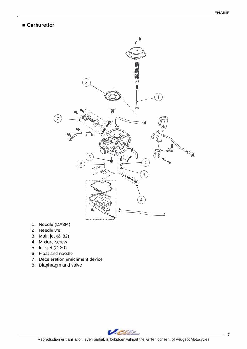
Carburettor
1. Needle (DA8M)2. Needle well3. Main jet (∅ 82)4. Mixture screw5. Idle jet (∅ 30)6. Float and needle7. Deceleration enrichment device8. Diaphragm and valve
1
2
3
4
5
8
7
6

ENGINE
8Reproduction or translation, even partial, is forbidden without the written consent of Peugeot Motocycles
Choke
1. Magneto flywheelc. Alternating current2. Regulator3. Choke4. Resistance (in series with the choke)
1
2
43
5 Ω - 5 W
JN
JN
JN
C
VE-NR
BA-NR
CYCLE PART
9Reproduction or translation, even partial, is forbidden without the written consent of Peugeot Motocycles
CYCLE PART
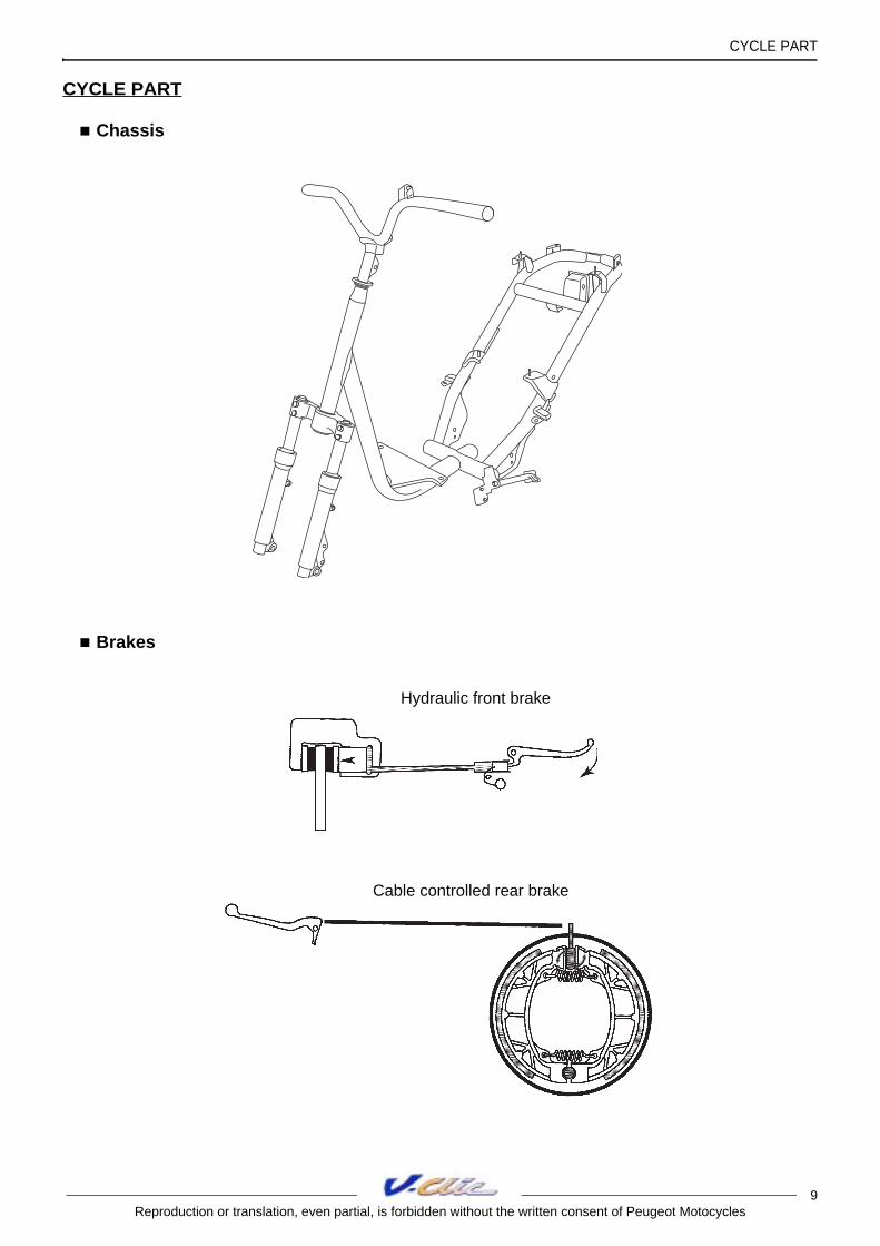
Chassis
Brakes
Hydraulic front brake
Cable controlled rear brake

CYCLE PART
10Reproduction or translation, even partial, is forbidden without the written consent of Peugeot Motocycles
Body panels
Description
1. Handlebar front fairing2. Handlebar rear fairing3. Legshield top panel4. Front lower legshields5. Legshield upper rear panel6. Legshield lower rear panel7. Utility hanger8. Protective plate9. Footboard panel
10. Battery case11. Battery cover12. Floor mat13. Central panel14. RH side fairing15. LH side fairing16. Rear cover17. Lower RH side fairing18. Lower LH side fairing
19. Lower rear fairing20. Storage compartment21. Saddle22. Luggage carrier rear panel23. Luggage carrier cover24. Bottom panel25. Mudflap26. Rear mudguard27. Front mudguard
2
3
5
6
8
711
12
9
10
1314
1516
17
18
19
20
21
22
23
24
25
26
4
27
1

CYCLE PART
11Reproduction or translation, even partial, is forbidden without the written consent of Peugeot Motocycles
Synoptics
(*) This item may be removed on its own
1
*
21
*
8
*
2
7
*
23
*
19
*27
*
22
17
25
*
18
26
*
CYCLE PART
12Reproduction or translation, even partial, is forbidden without the written consent of Peugeot Motocycles
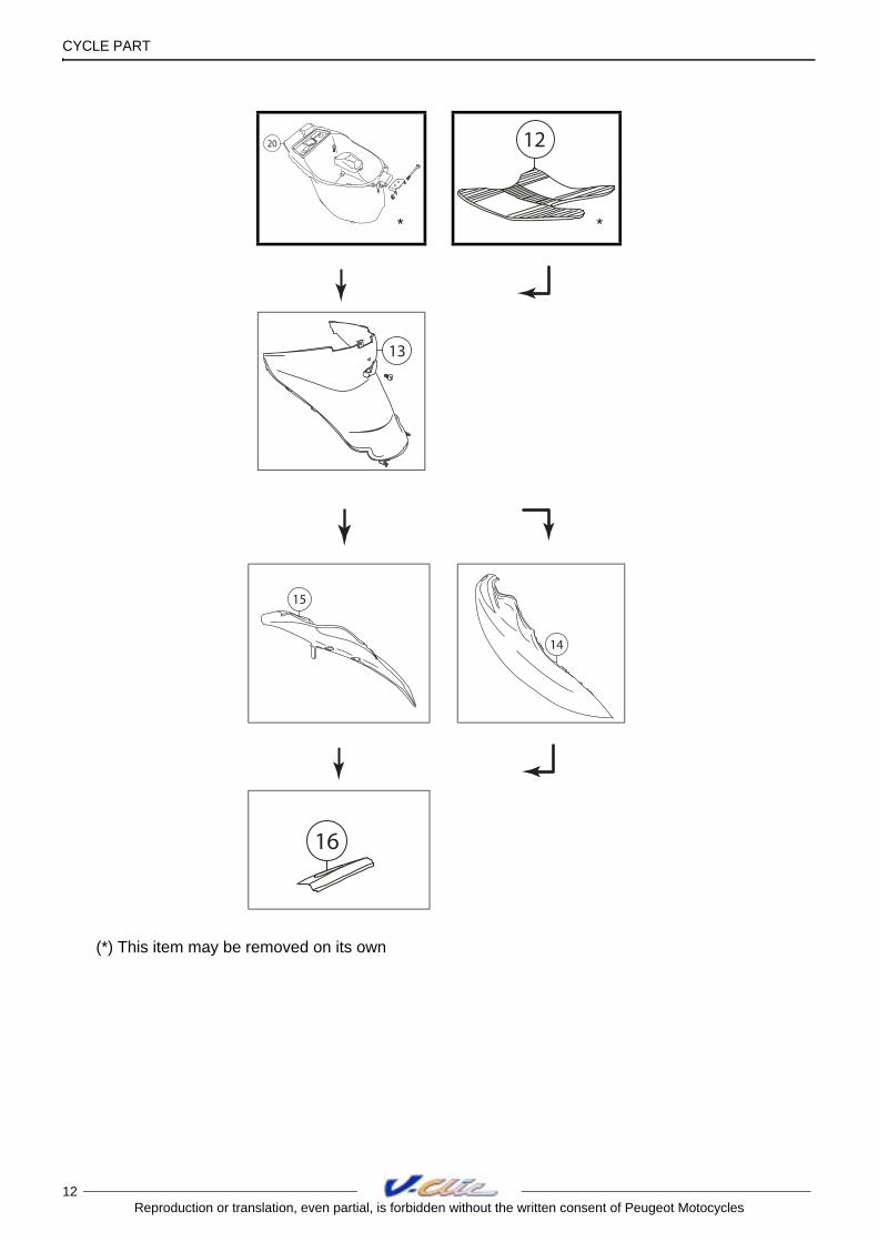
(*) This item may be removed on its own
20
*
12
*
13
15
14
16

CYCLE PART
13Reproduction or translation, even partial, is forbidden without the written consent of Peugeot Motocycles
(*) This item may be removed on its own
12
*
3
*
11
5
10
13
96
4
24

CYCLE PART
14Reproduction or translation, even partial, is forbidden without the written consent of Peugeot Motocycles
Instrument panel
Note: If the oil warning light goes red, change the engine oil.
Press with the tip of the ignition key in order to reset the warning light to green.
10102020
30304040 5050 6060 7070
8080
E
4545
2525
1010
20203030 4040
5050
0
Km / hKm / hmphmph
F

WIRING DIAGRAM
15Reproduction or translation, even partial, is forbidden without the written consent of Peugeot Motocycles
WIRING DIAGRAM
Lighting circuit
The lighting circuit is powered by AC circuit which is restricted in voltage.
Important:A faulty voltage regulator / voltage limiting device (3) (overvoltage) can burn out all the bulbs.
1. Magneto flywheeld. Battery charge current2. Ignition switch3. Regulator
4. Dip switch (main/low headlight)5. Low beam beadlight bulb6. Headlight bulb7. Parking light bulb
5
onon
ofof f
6
3
1
4
d
3
1
2
10 A10 A
12 V 4 Ah12 V 4 Ah
RGRGRGRG
NRNR
BABAJNJN
JNJN JNJNBEBEBABA
JNJN
4
6 75

WIRING DIAGRAM
16Reproduction or translation, even partial, is forbidden without the written consent of Peugeot Motocycles
Turn signal light circuit
The blinker unit is supplied with DC current when the ignition is on (2).
After selecting the operating side by means of the control knob (5), the blinker unit supplies the bulbs (6) with DC current.
The repeater (7) goes on at the same time on the instrument panel.
1. Magneto flywheeld. Battery charge current2. Ignition switch3. Regulator
4. Flasher unit5. Indicator relay6. Blinking lights bulbs7. Instrument panel indicator light
5
onon
ofof f
6
3
1
4
d
10 A10 A
12 V 4 Ah12 V 4 Ah
RGRGRGRG
4 x 10W
NRNR
VIVI
OROROROR
3
1
2
4
67
5
BA-NRBA-NR
BCBCBCBC

WIRING DIAGRAM
17Reproduction or translation, even partial, is forbidden without the written consent of Peugeot Motocycles
Fuel gauge circuit
The fuel gauge circuit is supplied with DC current.
The indicator (4) analyses the current intensity that goes through variable resistor which is connected to the float of the fuel gauge (5), and displays this value, which is in proportion to the level of the fuel level, on the indicator (4).
Full = Minimum resistance, therefore maximum current.
Empty = Maximum resistance, therefore minimum current.
Note: A short circuit on the wire which connects the indicator to the gauge will result in a level which is stuck at a maximum value. Otherwise (wire cut), the indicator remains stuck at the empty level.
1. Magneto flywheeld. Battery charge current2. Ignition switch
3. Regulator4. Fuel gauge5. Fuel gauge
BA-BEBA-BE JN-BAJN-BA
BA-NRBA-NR
10
100
3
1
2
4
5
5
onon
ofof f
6
3
1
4
d
10 A10 A
12 V 4 Ah12 V 4 Ah
RGRGRGRG

WIRING DIAGRAM
18Reproduction or translation, even partial, is forbidden without the written consent of Peugeot Motocycles
Stop light circuit
The stop light is supplied with DC current when the ignition is on.
1. Magneto flywheeld. Battery charge current2. Ignition switch
3. Regulator4. Stop light switch5. Stop light bulb
5
onon
ofof f
6
3
1
4
d
10 A10 A
12 V 4 Ah12 V 4 Ah
RGRGRGRG
NRNR JN-VEJN-VE
3
1
2
4
5
WIRING DIAGRAM
19Reproduction or translation, even partial, is forbidden without the written consent of Peugeot Motocycles
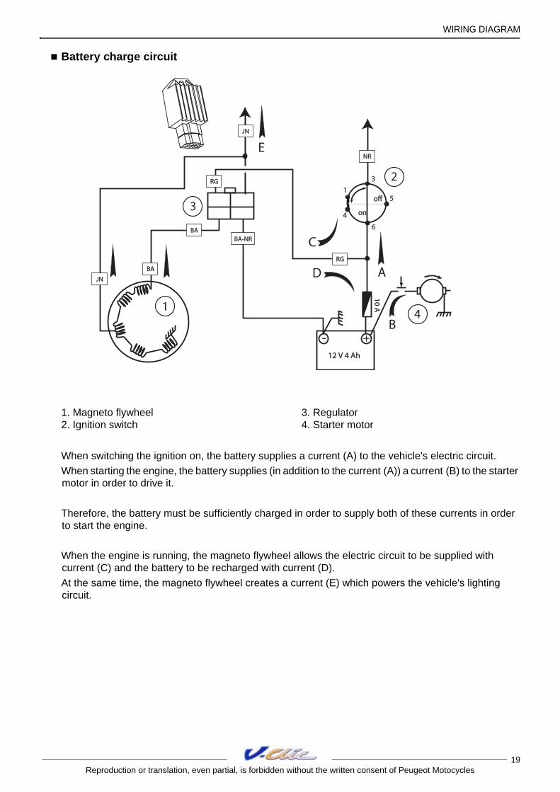
Battery charge circuit
When switching the ignition on, the battery supplies a current (A) to the vehicle's electric circuit.
When starting the engine, the battery supplies (in addition to the current (A)) a current (B) to the starter motor in order to drive it.
Therefore, the battery must be sufficiently charged in order to supply both of these currents in order to start the engine.
When the engine is running, the magneto flywheel allows the electric circuit to be supplied with current (C) and the battery to be recharged with current (D).
At the same time, the magneto flywheel creates a current (E) which powers the vehicle's lighting circuit.
1. Magneto flywheel2. Ignition switch
3. Regulator4. Starter motor
5
onon
offoff
6
3
1
4
12 V 4 Ah12 V 4 Ah
10 A10 A
NRNR
RGRG
+-
D
B
A
C
BABA
JNJN
BABA
RGRG
JNJN
E
BA-NRBA-NR
3
1
2
4

LOCATION OF COMPONENTS
20Reproduction or translation, even partial, is forbidden without the written consent of Peugeot Motocycles
LOCATION OF COMPONENTS
1. Battery2. Ignition sensor3. Ignition unit4. Oil level indicator5. HT coil6. Regulator7. Starter motor relay8. Horn9. 10 A fuse10. Kickstand switch
8
4
7
1
5
2 39
6
10

SERVICE SCHEDULE AND COMMISSIONING
21Reproduction or translation, even partial, is forbidden without the written consent of Peugeot Motocycles
SERVICE SCHEDULE AND COMMISSIONING
Heavy duty servicing is for vehicles used under "harsh" conditions: door-to-door deliveries, intensive urban use (courier), short journeys with engine cold, dusty areas, ambient temperature over 30°C.
Service operations. 500 kms or 1 months.
Every 5000 kms or 12 months.
Every 10000 kms.
Every 20000 kms.
Heavy duty servicing. 500 kms. Every
2500 kms.Every
5000 kms. Every
10000 kms. Check
Throttle cable play. C C C CSteering column play. C C C COperation of electrical equipment. C C C CCondition of the front brake hydraulic control.
C C C C
Condition of petrol pipes. C C C CCondition of oil pipes. C C C CTyre pressures. C C C CTyre condition, pressure and wear. C C C CCondition of the front suspension. C C C CCondition of the rear suspension. C C C CBrake fluid level. C C C CBattery electrolyte level*. C C C CEngine oil level. CTightness of nuts and bolts. C C C C
ChangeSpark plug. R R RInlet silencer/air filter. RFront brake pads #. C C CRear brake linings #. C C CDrive pulley bearings and guides #. C C CTransmission belt ##. R R REngine oil (+ clean strainer). R R R RBrake fluid. Once every 2 yearsRelay box. R R
Check and lubricate Kick starter mechanism. G GDrive pulley/Movable face. G G
Test machine On road. C C C C
C : CheckN : CleanR : ChangeG : Check and lubricate
* Depending on equipment# Change if necessary## Or once every 5 years

SPECIAL TOOLS
22Reproduction or translation, even partial, is forbidden without the written consent of Peugeot Motocycles
SPECIAL TOOLS
(*) New or modified tool
Tool N° Designation Used with Tool N° Designation Used
with
64765Engine mount
755982 752237Adjustable pin wrench
755982Engine mount
adapter64765 754035 Valve lifter 758595
758595Valve spring lifter adapter
754035 750806Flywheel
puller
759467(*)
Fixed flange locking tool
757990Lip seal push
tool


