65
1 • Technology Solutions for NOx Reduction • SO x NO x 2019 • By NAGAMOHAN

1
• Technology Solutions for NOx Reduction• SOx NOx 2019• By NAGAMOHAN
2
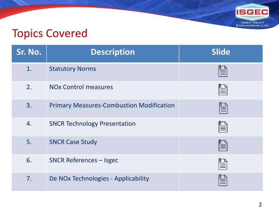
Topics CoveredSr. No. Description Slide
1. Statutory Norms
2. NOx Control measures
3. Primary Measures-Combustion Modification
4. SNCR Technology Presentation
5. SNCR Case Study
6. SNCR References – Isgec
7. De NOx Technologies - Applicability

3
STATUTORY NORMS
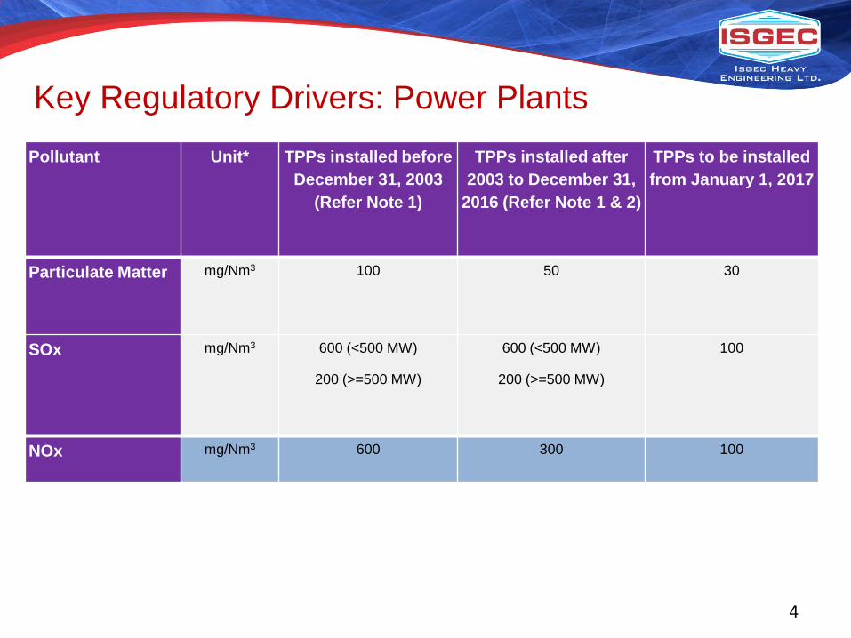
Key Regulatory Drivers: Power Plants
4
Pollutant Unit* TPPs installed before December 31, 2003
(Refer Note 1)
TPPs installed after 2003 to December 31,
2016 (Refer Note 1 & 2)
TPPs to be installed from January 1, 2017
Particulate Matter mg/Nm3 100 50 30
SOx mg/Nm3 600 (<500 MW)
200 (>=500 MW)
600 (<500 MW)
200 (>=500 MW)
100
NOx mg/Nm3 600 300 100

5
NOx CONTROL MEASURES

What is NOx?NOx Refers to Oxides of Nitrogen which include Nitric Oxide (NO),Nitrogen Dioxide (NO2) and may also include Nitrous Oxide (N2O) which iscommonly referred to as “laughing gas”.
The EPA defines NOx as “all oxides of Nitrogen except Nitrous Oxide”.
In combustion of fuels, there are two types of NOx formation.They are:•Thermal NOx - The concentration of “thermal NOx” is controlled by thenitrogen and oxygen molar concentrations and the temperature ofcombustion. Combustion at temperatures well below 1,300C (2,370F)forms much smaller concentrations of thermal NOx.
• Fuel NOx - Fuels that contain nitrogen (e.g., coal) create “fuel NOx” thatresults from oxidation of the already-ionized nitrogen contained in the fuel.

NOx CONTROL MEASURES
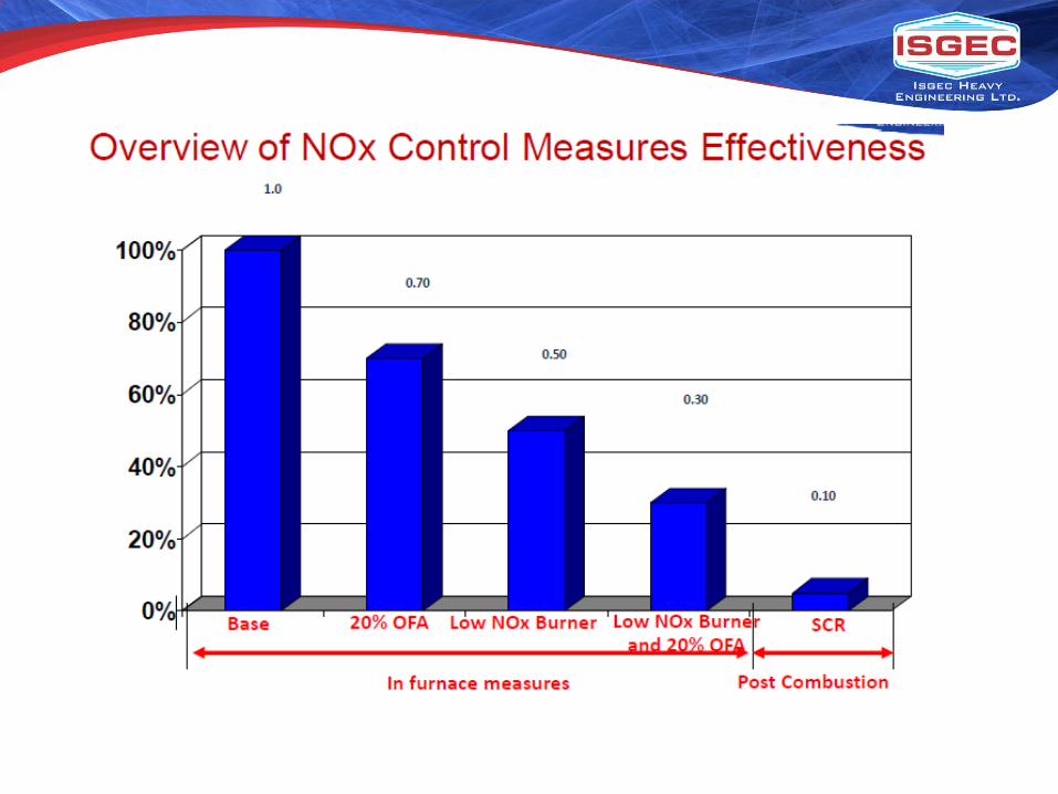
i. In-furnace Measures
Combustion Modifications: 50-60% reduction potential for older units where low
NOx burners / OFA were not originally provided.
ii. Post Combustion Measures
a. SNCR: 20 - 40% reduction potential for large PC fired units & upto 75% for small
industrial units on based on CFB / Bubbling bed combustion.
b. SCR: 85 - 90% reduction potential.
c. Hybrid of SCR & SNCR: Up to 60% reduction potential for large PC fired units.

9
PRIMARY MEASURES-COMBUSTION MODIFICATION

Primary Measure - Combustion Modifications
1. Low NOx Burner – For T-Fired and Wall Fired units2. OFA (Over Fire Air) - For T-Fired and Wall Fired units3. Mill Modification for Pulverized Coal Fineness
Improvement4. Low Capex, Negligible Opex5. 4 - 8 weeks shut down required depending on existing
configuration and modification required
BURNER24
AIRFLOWMEASURINGDEVICE
FLOWCONTROLDAMPERS
LOWERFURNACEAIRPORTS
SECONDARYAIR DUCTVENTURI
SECONDARYAIR DUCTS
REAR WALL BURNERS
REAR WALL WINDBOX
TYPICAL OVERFIREAIRPORT DAMPERS


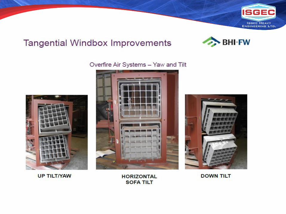
The SOFA wind boxes are fitted with BHI-FW’s patented Double Shroud (DS) air nozzle tip design Each tip has horizontal yaw as well as tilt adjustment capability
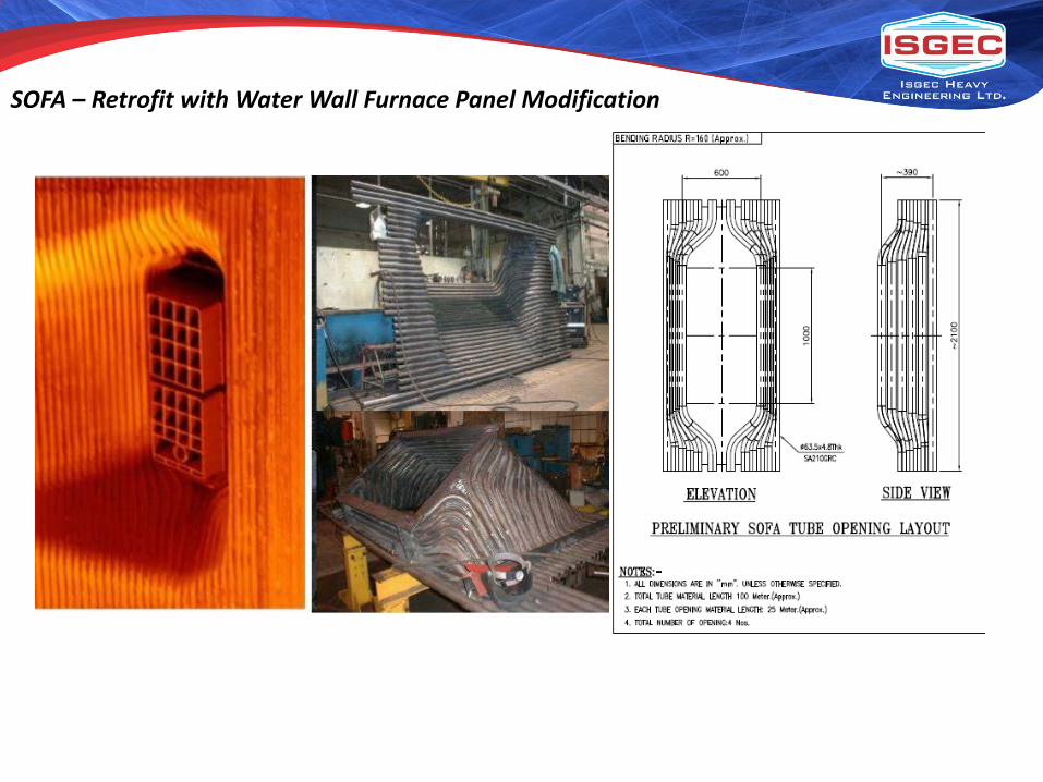
SOFA – Retrofit with Water Wall Furnace Panel Modification
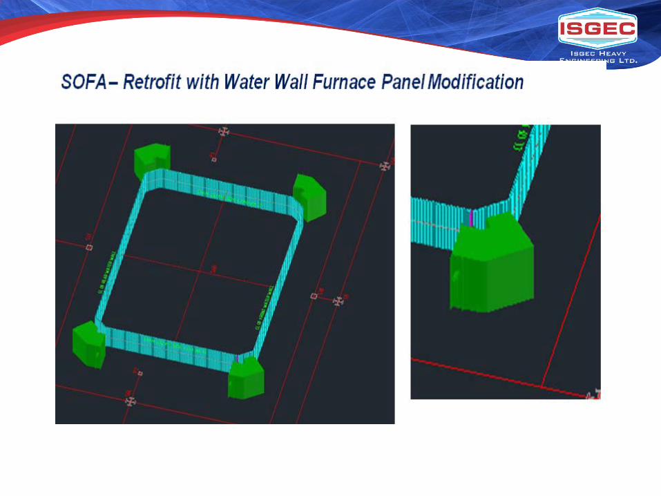

Secondary Air Duct Tapping & Routing for SOFA

Ref. list of BHI FW for Comb. Modification

Ref. list of BHI FW for Comb. Modification

20
Selective Non Catalytic Reduction (SNCR) Technology

Selective Non-Catalytic Reduction (SNCR) – Urea Based
SNCR Process Chemical Reactions
4NO + 2CO(NH2)2 + O2 4N2 + 4H2O + 2CO2
2NO2 + 2CO(NH2)2 + O2 3N2 + 4H2O + 2CO2
Nitrogen Oxides + Urea + Oxygen Nitrogen + Water Vapor + Carbon Dioxide
• NOx Removal Efficiency is Related to Normalized Stoichiometric Ratio (NSR)
– The Measure of the Rate at Which Urea is Added to the Flue Gas Relative to the Amount of Baseline NOx
NSR =Actual Mole Ratio of Urea to Baseline NOx
Theoretical Mole Ratio to Reduce One Mole of NOx
21

1290 1470 1650 1830 2010 2190 2370
NOx Reduction
Ammonia Slip
NOx Reduction
Ammonia Slip
Low Temperature Issues• Slow Droplet Evaporation• Slow Kinetics• Low OH Concentration• Ammonia Slip Increase
High Temperature Issues• Rapid Droplet Evaporation• Fast Kinetics• Increased OH Concentration• Urea Oxidation to NOx
SNCR “Right Side of Slope” Injection

• In-furnace, Post-combustion NOxControl
• Injection of Diluted Urea Reagent in Upper Furnace:– Low Energy, High Momentum
Droplets– Controlled Distribution through
specifically designed Injectors– In-furnace, Gas Phase Reactions
between NH3 & NOx• Process Reaction Temperature Range:
870 Deg. C – 1200 Deg. C• Reductions Ranging from 10 to 70
Percent.
NOxOUT® Selective Non-Catalytic Reduction (SNCR)
23

SNCR – Why Urea
Urea droplets formed by FTI injectors are characterized in test facilities using laser Doppler techniques.
24
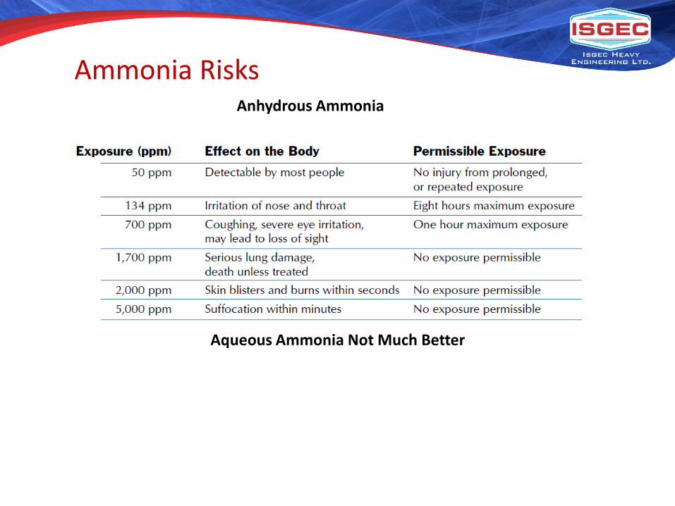
Anhydrous Ammonia
Aqueous Ammonia Not Much Better
Ammonia Risks

Critical Process Parameters• Furnace and Process Conditions
– Effective Temperature Window for Chemical Release and Reaction – 1600°F to 2200°F, Depending on Application
– Flue Gas Velocity and Residence Time Considerations
– Background Gas Composition – NOx, CO, O2, and Fuel Sulfur
• NOx Reduction and Distribution– Baseline Level and Target Emission Rate– Furnace Access to Facilitate Reagent
Distribution
• BOP Issues– NH3 Slip and SO3 Concentration at APH
Inlet Minimize Potential Formation of Ammonium Bisulfate (NH4)HSO4 – ABS
– HCl for Certain Applications
26
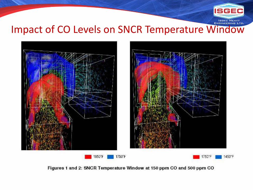
Impact of CO Levels on SNCR Temperature Window

SNCR Injection Strategies• NOxOUT® Technology
– Air Atomized Urea Injection
– Larger Droplet Size for Hot and/or Large Boilers and Furnaces
• High Energy Reagent Technology (HERT)– Mechanically Atomized Urea Injection via Injectors in Upper Furnace
– Recent Applications with Low Baseline Applications and Control Levels at or Below 0.100 lb/MMBtu
• Multiple Nozzle Lances (MNLs)– Air Atomized, Fine Mist
– Convection Pass Injection
• Combined Injection Strategy for Significant NOx Reduction with NH3 Low Slip Control
28
• Reagent Storage and Circulation– Circulation Module to be located in-doors and has pump
redundancy– Tanks sized for ten (10) days storage at full load
• Metering and Distribution– Control valve based metering modules for quick response
• Injectors– Investigating Wall Injectors Only
• DCS Control System• Option for Dry Urea Storage and Solutionizing
– Dry storage should be four (4) days storage at full load– Equipment to be located indoors
Typical SNCR Equipment
29

SNCR Simple Schematic

• Use: Store urea solution
• Diameter: 12’ to 14’ typical
• Height: 15’ to 35’
• Empty weight: 4,000 to 15,000 lbs.
• Filled weight: 200,000 to 450,000 lbs.
• Capacity: 10,000 to 45,000 gallon
• Construction: FRP
• Atmospheric pressure
• Delivered in one piece and can be set in place directly off the transport truck
• Ladders, cages, and railings included per OSHA requirements
• Individual fill line to each tank
• Furnished with expansion joints, manual valves, heater pads imbedded in tank walls
• Some assembly required
Urea Storage Tanks (40,000 gallon tanks)

• Use: Circulates Urea solution• Size: 4’ x 8’ x 6’H• Weight: 2,000lbs• Construction: Stainless steel• 100% automatically redundant VFD
pumps • Inline heater• Manual return pressure control valve• Stainless steel piping and sump
(containment) base• Sump base includes center drain
and is welded to steel checker plate deck
• All controls, transmitters, gauges, and valves included
• Power and controls wiring enclosure (trough) overhead
• Convenience power provided in enclosure
HFD Module (skid)

• Use: Supplies dilution water to IZM• Size: 4’ x 8’ x 6’H• Weight: 1,500lbs• Construction: Stainless or carbon
steel• 100% automatically redundant
VFD pumps • Maintains constant dilution water
pressure and flow to NOxOUT®
system even with supply fluctuations
• Stainless steel piping and base• Module base includes sump with
corner drains• Can be welded or bolted to deck or
structural steel• Controls, transmitters, gauges,
valves, and electrical equipment are included
Dilution Water Pressure Control Module

• Use: Separates and dilutes urea solution into zones
• Size: 4’ x 8’ x 6’H and up• Weight: 2,500lbs and up• Construction: Stainless steel• 2 injector zones and 2 MNLs
shown here with flanged outlets • Control valves, transmitters, and
motor op valves all wired to control panel
• Flow through circulation loop piping
• Stainless steel piping and sump base with forklift holes and removable lifting lugs
• Automatic water flush on normal shutdown (no flush on E-stop)
• Control panel includes PanelViewHMI
Independent Zone Metering Module
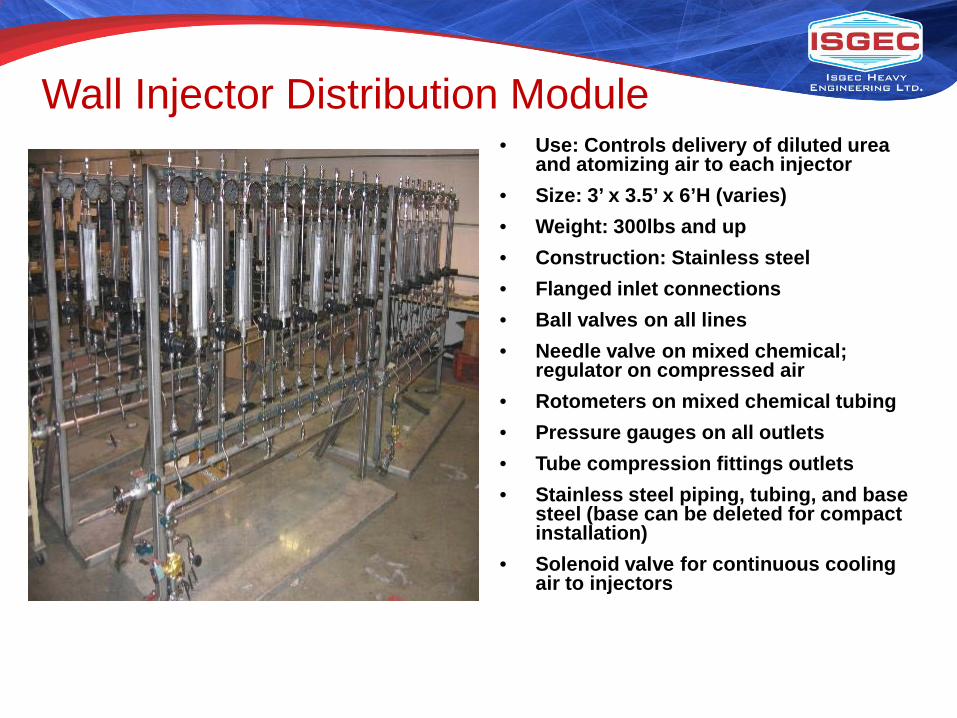
• Use: Controls delivery of diluted urea and atomizing air to each injector
• Size: 3’ x 3.5’ x 6’H (varies)• Weight: 300lbs and up• Construction: Stainless steel• Flanged inlet connections• Ball valves on all lines• Needle valve on mixed chemical;
regulator on compressed air• Rotometers on mixed chemical tubing • Pressure gauges on all outlets• Tube compression fittings outlets• Stainless steel piping, tubing, and base
steel (base can be deleted for compact installation)
• Solenoid valve for continuous cooling air to injectors
Wall Injector Distribution Module

• Use: Controls delivery of diluted urea and atomizing air to each injector and automatically retracts wall injectors when not in use
• Size: 3’ x 5.5’ x 6’ (varies)• Weight: 350lbs and up• Construction: Stainless steel• Same as wall injector Distribution
Module• Switch mounted on retract panel
allows local insert, retract, or automatic mode
• Actual module is thin (right side view)
Distribution Module with Retract Panel
Control panel for injector retractors (if used)
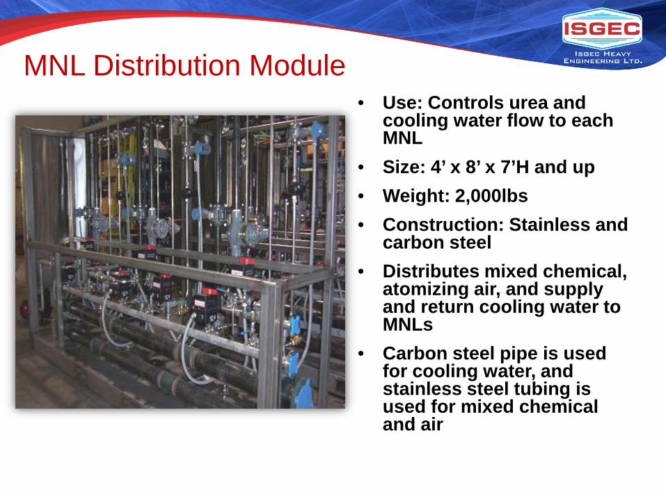
• Use: Controls urea and cooling water flow to each MNL
• Size: 4’ x 8’ x 7’H and up• Weight: 2,000lbs• Construction: Stainless and
carbon steel• Distributes mixed chemical,
atomizing air, and supply and return cooling water to MNLs
• Carbon steel pipe is used for cooling water, and stainless steel tubing is used for mixed chemical and air
MNL Distribution Module

• Use: Injection of diluted urea into boiler
• Size: 36” but can change depending on boiler wall construction
• Weight: 10lbs and up• Construction: Stainless steel• Approximately ¾” diameter• Requires minimum 1” boiler port• Atomizing/cooling air and mixed
chemical connections on body• Quick connects for chemical and
air automatically shut off when disconnected
• Camlock connection to adjust insertion depth
• Port should be provided with aspirating air on positive pressure boiler
Standard SNCR Wall Injector

SNCR Wall Injector in Operation

• Use: Automatic injector retract
• Size: 24”L x 6”W x15”H• Total weight: 70lbs• Construction: Stainless steel
injector, painted carbon steel retract
• Uses same wall injector in retract assembly
• Retract flange mounted directly to boiler port; flanges furnished by FTI
• Air insert, spring retract• Utilized on lower zones to
minimize injector wear• Mixed chemical flow stops
upon retract; cooling air continues
• Spacer on retract to adjust insertion depth
SNCR Injector with Retract

Retract & Injector
Assembled
Installed

SNCR Case Study

Westar Jeffrey Energy Center• Three (3) 800 MW
T-Fired Units• Unit 1 - Hitachi SCR• Units 2 and 3 -
Combustion Modifications and FTI SNCR Systems
43
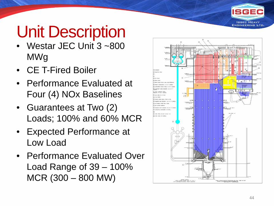
Unit Description• Westar JEC Unit 3 ~800
MWg• CE T-Fired Boiler• Performance Evaluated at
Four (4) NOx Baselines• Guarantees at Two (2)
Loads; 100% and 60% MCR• Expected Performance at
Low Load• Performance Evaluated Over
Load Range of 39 – 100% MCR (300 – 800 MW)
44
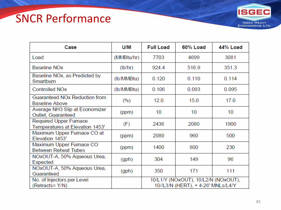
SNCR Performance
45
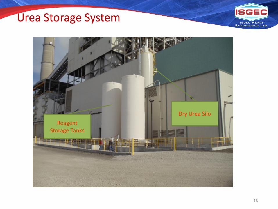
Urea Storage System
Reagent Storage Tanks
Dry Urea Silo
46
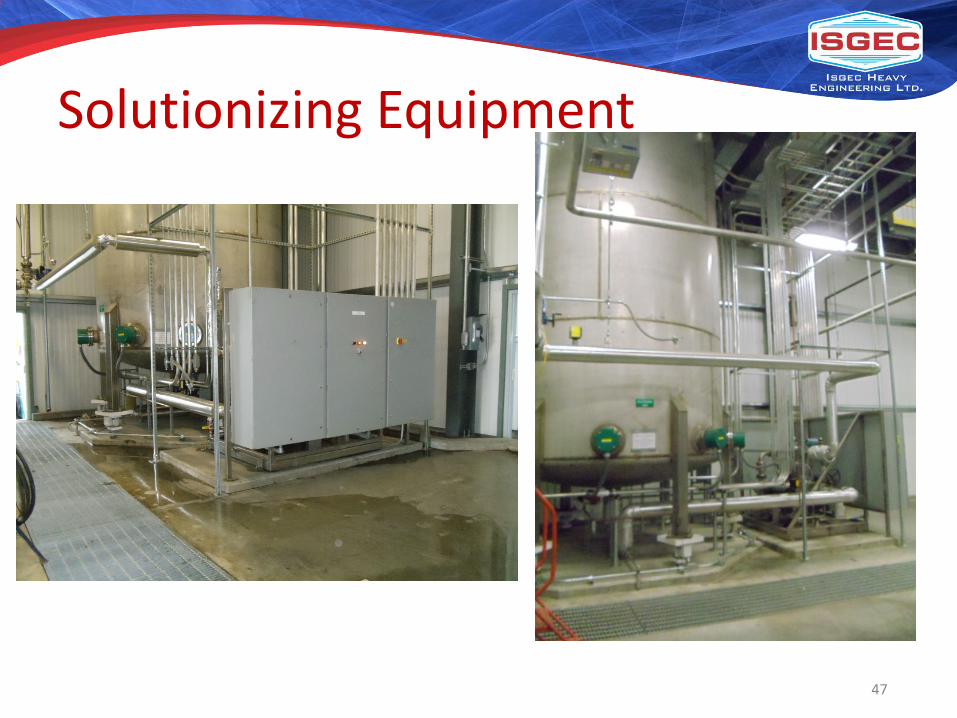
Solutionizing Equipment
47

Circulation Module
48

Metering Module
49

Distribution Module and Building
50
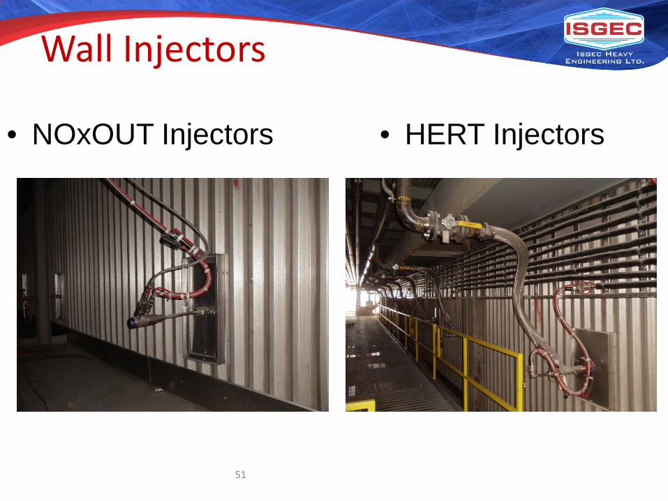
Wall Injectors
• NOxOUT Injectors • HERT Injectors
51
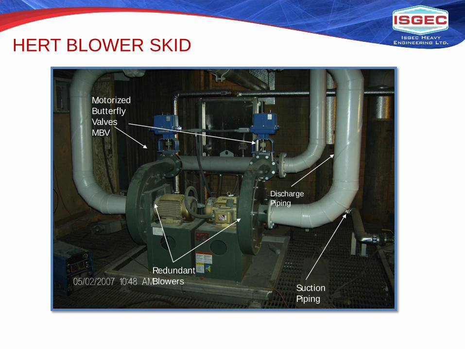
Redundant Blowers
Suction Piping
Discharge Piping
Motorized Butterfly Valves MBV
HERT BLOWER SKID

Blower Air Isolation Valve
Dilution Water & UREA Isolation Valve
Injector
HERT INJECTORS
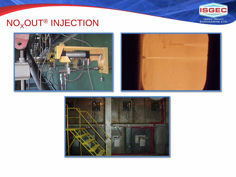
NOXOUT® INJECTION

Multiple Nozzle Lance (MNL)

MNL IN THE BOILER

MNL TESTING

Recent SNCR Applications
• Westar Jeffrey Energy Center– Units 2 & 3 775 MW CE T-Fired Units
• Nipsco Schahfer– Unit 15 500 MW FW Wall Fired
• Alcoa – Warrick Station– Three (3) 170 MW B&W Wall Fired Units
• Tri-State Generation and Transmission (On-going)– Craig Unit 3 448MWn B&W Opposed Wall Fired
• CLECO Power– Rodemacher 535 MW Opposed Wall Fired– Dolet Hills 700 MW Opposed Wall Fired
• MidAmerican Energy George Neal Units 3 & 4– Unit 3 530 MW FW Opposed Wall Fired Unit– Unit 4 695 MW FW Opposed Wall Fired Unit

Fuel Tech Experience and Benefits• Extensive Commercial Experience
– Over 100 LNB/OFA Systems from 20 MW to 1200 MW– Over 650 NOxOUT and HERT Systems Worldwide, More Than 100
Utility Applications– Over 55,000 MW of SCR Design, 20,000 MW AIG Tuning Experience
Worldwide– NOxOUT ULTRA® Systems, Over 100 Units to Date, 5 to 1,250 PPH of
SCR Reagent Feed Systems• Fuels and Boiler Types
– Coal, Biomass (Wood, MSW, Bagasse, Etc.), Gas, Oil, Tires, Etc.– T-Fired, Stoker, Wall Fired, Down Fired, Incinerators, CFB, BFB, Etc.
• Quality Equipment with Low Maintenance Cost– Stainless Steel Design for Long Life and Durability
• Guaranteed Performance – NOx Reduction, NH3 Slip, Reagent Consumption, Power
Consumption, CO, LOI

Isgec References - SNCRNOx Reduction Technology

Modern Cement and Mining Corporation
• Application: CFBC Boiler• Capacity : 150 TPH• Location: Jordan• Fuel : Coal• NOx Baseline: 315 mg/Nm3• No. of Injectors: 7 (AutoRetract in Combustor) +
6 (in Compact Separator)• NOx Reduction Efficiency: 36.5%
Unloading & Recirculation Module
Water Boost Module
Metering cum distribution Module
Modern Karton Pulp & Paper
• Application: CFBC Boiler• Capacity : 240 TPH• Location: Turkey• Fuel : Coal• NOx Baseline: 500 mg/Nm3• No. of Injectors: 10 (AutoRetract in Combustor) + 10 (in Compact Separator)• NOx Reduction Efficiency: 70%

63
DeNOx Technologies - Applicability

64
Sr. No.
Industry Application NOx Reduction Efficiency
Technology Preference
RecommendedReagent
1 Power Utility Boilers ≤40% SNCR Urea Solution
2 Power Utility Boilers 40% - 70% ASCR Urea Solution
3 Power Utility Boilers ≥70% SCR Anhydrous Ammonia/Urea
4 Industrial CPP
CFB/AFB/TG Boilers
≤75% SNCR Aqueous Ammonia (19 –25% Solution)
5 Cement Kiln/Calciner ≤75% SNCR Aqueous Ammonia (19 –25% Solution)
DeNOx Technology Applicability: Conclusion

Thanks
65


