Heeyoung Jung ETRI Korea Tel: +82 42 860 4928 Email: [email protected]Contact: Nam-Seok Ko ETRI Korea Tel: +82-42-860-5560 Email: [email protected]Attention: This is not a publication made available to the public, but an internal ITU-T Document intended only for use by the Member States of ITU, by ITU-T Sector Members and Associates, and their respective staff and collaborators in their ITU related work. It shall not be made available to, and used by, any other persons or entities without the prior written consent of ITU-T. INTERNATIONAL TELECOMMUNICATION UNION NGN-GSI TD 33 (NGN-GSI) TELECOMMUNICATION STANDARDIZATION SECTOR STUDY PERIOD 2005-2008 English only Original: English Question(s): 2/19, 6/13 Geneva, 12-23 May 2008 TEMPORARY DOCUMENT Source: Editors Title: Draft Recommendation Q.LMF (version 0.8 9 ) 1. Introduction This is an output document of the 2008 MayNGN-GSI meeting on LMF (Framework of Location Management for Next Generation Networks). LMF has so far been progressed as indicated by the following version history: Version Date Meeting 0.1 24 ~ 28 April 2006 NGN-GSI Meeting 0.2 19 ~ 27 July 2006 SG19 & NGN-GSI Meeting 0.3 24 Oct. ~ 3 Nov. 2006 NGN-GSI Meeting 0.4 19 ~ 26 April 2007 SG19 & NGN-GSI Meeting 0.5 29 June ~ 5 July 2007 Q.2/19 and Q.6/13 Electronic Meeting 0.6 11 ~ 21 September 2007 NGN-GSI Meeting 0.7 21 ~ 26 November 2007 Q.2/19 and Q.6/13 Electronic Meeting 0.8 17 ~ 24 January 2008 SG19 & NGN-GSI Meeting 0.9 12 ~ 23 May 2008 NGN-GSI Meeting
Attention: This is not a publication made available to the public, but an internal ITU-T Document intended only for use by the Member States of ITU, by ITU-T Sector Members and Associates, and their respective staff and collaborators in their ITU related work. It shall not be made available to, and used by, any other persons or entities without the prior written consent of ITU-T.
INTERNATIONAL TELECOMMUNICATION UNION NGN-GSI
TD 33 (NGN-GSI)TELECOMMUNICATION STANDARDIZATION SECTOR STUDY PERIOD 2005-2008 English only
Original: EnglishQuestion(s): 2/19, 6/13 Geneva, 12-23 May 2008
TEMPORARY DOCUMENT
Source: Editors
Title: Draft Recommendation Q.LMF (version 0.89)
1. Introduction
This is an output document of the 2008 MayNGN-GSI meeting on LMF (Framework of Location Management for Next Generation Networks).
LMF has so far been progressed as indicated by the following version history:
Version Date Meeting
0.1 24 ~ 28 April 2006 NGN-GSI Meeting 0.2 19 ~ 27 July 2006 SG19 & NGN-GSI Meeting 0.3 24 Oct. ~ 3 Nov. 2006 NGN-GSI Meeting 0.4 19 ~ 26 April 2007 SG19 & NGN-GSI Meeting 0.5 29 June ~ 5 July 2007 Q.2/19 and Q.6/13 Electronic Meeting 0.6 11 ~ 21 September 2007 NGN-GSI Meeting 0.7 21 ~ 26 November 2007 Q.2/19 and Q.6/13 Electronic Meeting 0.8 17 ~ 24 January 2008 SG19 & NGN-GSI Meeting 0.9 12 ~ 23 May 2008 NGN-GSI Meeting
- 2 - TD xxx (GEN/19) TD xxx (WP 2/13)
Framework of Location Management for NGN
Summary
TBD
Keywords
NGN, IMT, Location Management, Framework
Introduction
This Recommendation describes a framework of mobility management (MM) for Next Generation Networks (NGN). This work has been motivated from the observation that NGN continues to evolve toward the convergence of fixed and wireless/mobile networks, and thus the mobility management is an essential functionality to provide seamless mobility for the NGN users and services.
This Recommendation is a part of the MM framework for NGN. The MM framework will be designed with a couple of Recommendations, rather than a single Recommendation, as a suite of the framework of mobility management for NGN. This is because the design of the MM framework includes a variety of technical issues to be addressed. Furthermore, those design issues are also associated with a wide variety of mobility scenarios and protocols. In this respect, the MM framework for NGN is described with a family of the following Recommendations:
Recommendation MMF: Generic Framework of Mobility Management for NGN;
Recommendation LMF: Framework of Location Management for NGN; and
Recommendation HCF: Framework of Handover Management for NGN.
This RecommendationLMF will describes the functional architecture and information flows for specific to the location management in NGN, which includes the followings:
Design issues to be considered for specific to either location management;
Functional entities associated with location management and the relationship with the other NGN functional entities; and
Procedural information flows for location management between NGN users, MM functional entities, and the other NGN functional entities.
This Recommendation
It is noted that the NGN would be evolved so as to support a variety of mobility types such as terminal mobility, service mobility, personal mobility and network mobility, etc. At present, the works on MM framework will This Recommendation focuses on the location management issues associated with the terminal mobility in the network-layer utilizing link layer information. The other mobility issues such as service mobility, personal mobility and network mobility will be addressed in the other Recommendations.
2 References
The following ITU-T Recommendations and other references contain provisions, which, through reference in this text, constitute provisions of this Recommendation. At the time of publication, the editions indicated were valid. All Recommendations and other references are subject to revision; users of this Recommendation are therefore encouraged to investigate the possibility of applying the most recent edition of the Recommendations and other references listed below. A list of the currently valid ITU-T Recommendations is regularly published.
The reference to a document within this Recommendation does not give it, as a stand-alone document, the status of a Recommendation
[1] ITU-T Supplement Q.sup52 (2004), Technical Report on Mobility Management Requirements for Systems beyond IMT-2000
[2] ITU-T Draft New Recommendation MMR (working in progress), Mobility Management Requirements for Fixed and Mobile Convergence Networks
[3] ITU-T Draft New Recommendation MMF (working in progress), Generic Framework of Mobility Management for Fixed and Mobile Convergence Networks
[4] NGN Focus Group draft deliverable, “Mobility Management Capability Requirements for NGN”
- 6 - TD xxx (GEN/19) TD xxx (WP 2/13)
[5] ITU-T Recommendation Q.1701 (1999), Signalling Requirements and Protocols for IMT-2000
[6] ITU-T Recommendation Q.1702 (2002), Long-term Vision of Network Aspects for Systems beyond IMT-2000
[7] ITU-T Recommendation Q.1711 (1999), Network Functional Model for IMT-2000
[8] ITU-T Recommendation Q.1721 (2000), Information Flows for IMT-2000 Capability Set 1
[9] ITU-T Recommendation Q.1741.3 (2003), IMT-2000 References to Release 5 of GSM evolved UMTS Core Network
[10] ITU-T Recommendation Q.1742.3 (2004), IMT-2000 References (approved as of 30 June 2003) to ANSI-41 Evolved Core Network with cdma2000 Access Network
[11] ITU-T Recommendation Q.1761 (2004), Principles and requirements for convergence of fixed and existing IMT-2000 systems
[12] ITU-T Recommendation Y.2001 (2004), General overview of NGN
[13] ITU-T Recommendation Y.2011 (2004), General principles and general reference model for Next Generation Networks
[14] ITU-T Recommendation Y.2012 (2006), Functional requirements and architecture of the NGN
[15] ITU-T Recommendation Y.2091 (2007), Terms and definitions for Next Generation Networks
[16] ITU-R Recommendation M.687-2 (1997), International Mobile Telecommunications-2000
[17] ITU-R Recommendation M.1034-1 (1997), Requirements for the radio interface(s) for (IMT-2000)
[18] ITU-R Recommendation M.1168 (1995), Framework of IMT-2000
[19] ITU-R Recommendation M.1224 (1997), Vocabulary of terms for IMT-2000
3 Definitions This Recommendation uses the definitions and terms that have been defined in the draft Recommendations MMR and MMF.
In addition, the following terms are used in this Recommendation:
[Editor’s Note: definitions section will be filled as the work progresses].
- 7 - TD xxx (GEN/19) TD xxx (WP 2/13)
Location Management
A process that enables the network to determine a mobile’s current location, i.e., the mobile’s current network attachment point where the mobile can receive traffic from the network.
4 Abbreviations
[Editor’s Note: This section will be updated as the work progresses]
A-LMF Access-Location Management Function AAA Authentication, Authorization and Accounting AN Access Network BU Binding Update C-LMF Central-Location Management Function CCoA Co-located Care of Address CH Correspondent Host CN Core Network CoA Care of Address DHCP Dynamic Host Configuration FA Foreign Agent FE Functional Entity FRA Functional Requirements and Architecture HA Home Agent HCF Handover Control Function HoA Home Address ID Identification IETF Internet Engineering Task Force IP Internet Protocol IPCP IP Control Protocol LM Location Management LMF Location Management Framework/Function MIP Mobile IP MIP4 Mobile IPv4 MIP6 Mobile IPv6 MM Mobility Management MMCF Mobility Management Control Function
- 8 - TD xxx (GEN/19) TD xxx (WP 2/13)
MMR Mobility Management Requirement NGN Next Generation Network DHCP Dynamic Host Configuration QoS Quality of Service SIP Session Initiation Protocol SCTP Stream Control Transmission Protocol TCP Transmission Control Protocol UA User Agent UDP User Datagram Protocol UE User Equipment URI Uniform Resource Identifier
5 Overview High Level Functions of Location Management
5.1 High Level Functional Overview
The location management functionality in this Recommendation is to keep track of the mobile NGN users/terminalsUEs in the network by identifying and maintaining where the mobile user isUEs are in the network and by maintaining the location information of the mobile user as it continues to move around in the network. This will ensures that the IP traffic from the other UEs can reach a corresponding caller can deliver user data to the mobile users/terminalsUEs correctly. More precisely, the location management function has two main roles in NGN architecture. The first role of the location management function is to manage the transport and/or geographical locations of mobile UEs. The DSLAM identifier and logical port number of DSLAM are the examples of transport location information. The other role of the location management function for the mobile UEs is to manage the relation of UID and LIDs (persistent LID and temporary LID). Persistent IP address (PIA) and temporary IP address (TIA) are typical examples of persistent LID and temporary LID, respectively. Persistent IP address is not changed during the movement of UE, after it has once been allocated to mobile UE. However, it is noted that a different persistent IP address can be allocated to the same UE in certain cases, for example, when the UE is rebooted. The home address of MIP is an example of the persistent IP address. On the other hand, a different temporary IP address is allocated to a UE whenever the TE moves into a new subnet. The care-of address of MIP is an example of the temporary IP address.
For this purpose, aA set of the LM-related Ffunctional Entities entities (FesFEs) in NGN architecture will may be used to identify and maintain the mobility location information of a mobile user/terminalUEs. New functional entities such as ALM-FE, CLM-FE and VLM-FE are defined in clause 6.2 to support location management in NGN. The location information maintained in the LM-related FEs will be referred to in the progress procedure of the connection establishment and user data transfer toward the concerned mobile UEs.
This Recommendation will describe the reference functional architecture and the procedural information flows for location management. Based on the LMF framework designed in this
- 9 - TD xxx (GEN/19) TD xxx (WP 2/13)
Recommendation, a couple of existing or possibly new location management schemes/protocols can be analyzed in the perspective of MM for NGN.
In the design of the LMF, the following basic functions will be considered for location management:
5.21 Network Attachment
5.21.1Terminal/UserUE Identification
The MM protocols for NGN must specify how users/terminals are to be authenticated, authorized accounted, and secured for mobility services using standard AAA and security mechanisms.
The result of the AAA functionality will be a yes/no decision on the service request made by a user. As a next step, the access network configuration will be adapted to the mobile/nomadic user such that it satisfies the particular Quality of Service (QoS) level and security association for the requested service. These mechanisms should be based on the user’s subscription profile and the technical resource constraints of the respective access networks.
While it is envisaged that many users will have a terminal for their exclusive personal use, there will also be many cases where terminals must be shared among multiple users (e.g., public telephones) and cases where a particular user, for good and valid reasons, may need to borrow a terminal from another user who normally has exclusive use of his terminal but is willing to let it be used by someone else for good and valid reasons (e.g., an emergency call when the terminal has exhausted its battery.) For these and other circumstances, it is considered essential that the mechanisms for identifying users and terminals be separate, that is, that a user’s identify is distinct from a terminal’s identity, and that there is a non-permanent association of a user with a particular terminal, which may be transitory or long lasting, depending on the circumstances. Users may also have multiple terminals and will want to be able to transfer from one terminal to another according to their needs. As the overall context is mobility, it is also important that geographic information be separate from the user identity and the terminal identity. The mechanisms to handle all of these will require careful investigation since it will also be essential that they are interoperable with existing naming, numbering, addressing and routing mechanisms.In order to access NGN from various access networks, and get authentication, authorization and accounting services, UID shall be used. The UID used for this purpose may depend on the authentication, authorization and accounting mechanisms applied on the access network where UE is connected to. The UID may typically contain the domain name of the home operator, as we can see in the example of “user@domain”. The exact user identification architecture will follow the results of idM-GSI.
Editor's Note – There is an opinion that the UID’s dependency on the AAA procedure is not clear, and it needs to be clarified by the contribution.
5.21. 2 Configuration of location Location ID
- 10 - TD xxx (GEN/19) TD xxx (WP 2/13)
As described in Y.1707, LID can be classified into persistent LID and temporary LID. Persistent IP address is an example of the persistent LID, which may be kept the same regardless of UE’s movement and temporary IP address is an example of temporary LID, which may be changed when a UE moves into an access network whose subnet prefix is different from those of persistent IP or current temporary IP address. For example, It is noted that the user ID for an UE is given by the home operator or service provider. The user ID may typically contain the domain name of the home operator, as we can see in the example of “user@domain”.
When an UE enters a new network region, it must first get its current location ID (e.g., a routable IP address). For this purpose, the UE may use the Dynamic Host Configuration Protocol (DHCP), IP Control Protocol (IPCP), or IPv6 stateless IP address auto-configuration may be used for configuring the LID of a UE. The location ID will be typically an IP address or an identifier to be converted in the unique IP address, which may include the information on the local network (or local network operator).
To provide efficiently envisioned services in NGN environment such as location-based service, the location ID may include L2 identifier as well as L3 identifier.
In the configuration of a location LID, the UE may be enforced to contact with the AAA server for authentication and authorization. In this Recommendation, the MMFit is assumes assumed that LID of the UE could get an IP addressallocated using the relevant location ID IP address configuration and AAA scheme. The For example, temporary IP address may be configured by NAC-FE and persistent IP address may be configured by NAC-FE or TUP-FE with being associated with relevant AAA procedures. detailed procedures of the address configuration and interaction with the AAA servers are outside the scope of this recommendation.
5. 2 3 Location Registration and Update
Each UE should register its current location Location informationID (e.g. IP address) for each UE should be maintained with by its associated location management FEs, when it awares that not in Home network in order to be tracked in by the networkNGN.
When a UE attaches to an access network initially and the LIDs are allocated, it will perform location registration procedure to maintain the association between UID and LIDs. The registration procedure may involve the update of relevant databases in home and visited network. Whenever the UE moves into another new region and gets a new LID, it will update the location information change.
Each UE should update its location ID whenever it moves into another new region and gets a new location ID. Each location management FE will keep and maintain the information of mapping between User ID and Location ID for the concerned UE.
- 11 - TD xxx (GEN/19) TD xxx (WP 2/13)
5.3 4 Location Query and Packet Delivery
5.34.1 Location query Query and replyResponse
The LM functions in network manage the mapping relation between UID and LIDs. A UE or A-LMF may need the LIDs of the other UEs or A-LMFs before it starts to communicate with each other depending on the mobility management protocols. When another external or internal (fixed or mobile) terminal, named the ‘caller,’ wants to communicate with the mobile UE, first of all, the caller terminal should know the current location ID of the called UE. In this case, the location information managed by LM will be used. The caller calling UEterminal in host-based mobility or A-LMF in network-based mobility will may first query appropriate the home LM functional entities about the current location LID (IP address) offor the UID of the called UE. Then, the calling UE may send IP traffic to the correct location of called UE after receiving the response for the location query.
It is noted that the location query and responseply procedures could be differently applied to the services or applications,different depending on whether or not they need out-of-band signaling for call/session setup.
5.34.2 Paging for Idle TerminalsUEs
The paging capability for to supporting idle mode terminals UEs is essentialmay be provided in large-scale networks because it provides power saving in mobile terminals UEs as well as signalling reduction in networks, which improve the scalability of NGN. In particular,The paging support capability needs to be provided together with location management.
When an mobile UE goes into the idle (or dormant) state, it may registers with a Paging paging management function. The UE will may also update its paging area, whenever it changes the paging area. The paging management could be implemented in the access link layer and/or IP-based network layer. In the LMF, the IP-based paging may be concerned but does not preclude the use of link layer specific capabilities provided within the access networks., since the paging schemes in the underlying access link layer are subject to a specific access technology.
5.34.3 Packet transferTransfer
After getting the current location of the UE, now the caller calling terminal UE will begin the call/session establishment and/or the data transport process with the destination called UE. The IP data packet format may vary depending on the mobility protocols.
5.4 5 Network Detachment
[Editor’s Note: This subsection will describe the detachment procedure from NGN, more specifically MMCF. Contributions are requested].
- 12 - TD xxx (GEN/19) TD xxx (WP 2/13)
UEs can be detached when a UE decides not to access the services provided by the network or the network decides to stop providing services to the UE. The followings are the examples of the reasons:
- UE is power off
- Radio signal of wireless access network gets severely deteriorated
- User’s subscription is removed
A UE can inform the network that it does not want to use network access or network can inform the UE that it does not support network access for the UE. The detachment procedure can be done either explicitly or implicitly depending on the reasons for the detachment. A UE or network can explicitly request detach and signal each other. For example, when a UE is power off or user’s subscription is removed, the detachment will be requested explicitly. On the other hand, network may detach UEs without notifying the UE when the network presumes that it is not able to communicate with the UE due to radio conditions.
6 Reference Functional Architecture of Location Management
6.1 Basic Functional ArchitectureOverview
The figure 1 shows general model to support the consistency of conceptual function between LMF and NGN architecture.
- 13 - TD xxx (GEN/19) TD xxx (WP 2/13)
Figure 1. Conceptual model for location management
The separation between control plane and transport plane is a basic assumption for location management (LM). LM The Location Management Function (LMF) is composed into Access-Location Management Function (A-LMF) and Central-Location Management Function (C-LMF). These location management functions also could be distributed between a visited network and a home network.
- 14 - TD xxx (GEN/19) TD xxx (WP 2/13)
The C-LMF include following functionalities:
- Managing the binding information between User ID (UID) and LIDs (persistent LID and temporal LID) of a UE for the location registration and update procedures
- Performing visitor location management functions for UEs residing in the visited network
- Receiving and responding the location query from A-LMF or UE
- Rejecting the location registration, update, and query request for the C-LMF’s overload or consideration of administrative policies and so on, by responding to the A-LMF with the location registration, update, and query response message which may contain a redirection indication and information about a redirected C-LMF
The A-LMF include following functionalities:
- Obtaining the location information of one or multiple C-LMFs
- Initiating the location registration, update and query instead of UE to C-LMF in the case of network-based location management
- Re-initiating the location registration, update and query to the redirected C-LMF or another candidate C-LMF chosen from the list of C-LMFs when a C-LMF rejected the request
- Delivering the location registration, update and query messages from UE to C-LMF in the case of host-based location management
- Exchanging the location information for UE moving between A-LMFs
UE, User equipment, also may need a LMF to support location management procedure, for host-based location management, for example, sending location update (LU) message and receiving location update acknowledge (LU-ACK) message.
LMF may be located at transport control function or service control function. A-LMF and C-LMF are LM is likely to be located at A-LMF for various access network and C-LMF for core network, respectively. Especially C-LMF supports the capability to provide the control connection with other networks.
Based on this generalized conceptual model for location management, other location management functions for personal/service mobility management also could be added.
The LMF comprises the following functional entities:
- Central Mobility Location Management Functional Entity (CLM-FE)
The LMF has interaction with the following NGN functions:
- Network Attachment Control Function (NACF)
- Resource Admission Control Function (RACF)
- Handover Control Function (HCF)
Functional entities in the LMF may be distributed over two administrative domains.
6. 2 Functional Entities
Editor’s Note : In this clause, the logical functional entities are defined for LMF. These FEs are only defined in MM point of view and do not preclude to define detailed functional entities in NGN FRA.
The Access Mobility Location Management Functional Entity (ALM-FE) manages the relation between UID and LIDs (persistent LID and temporary LID) in A-LMF. Persistent IP address and temporary IP address are typical examples of the persistent LID and temporary LID, respectively. Persistent IP address is allocated to UE and kept the same regardless of UE’s movement. The address can be changed but would not change easily. The temporary IP address is allocated to UE when a UE moves out of the access network having the persistent IP address’s subnet prefix and changed when the UE moves into an access network whose subnet prefix is different from that of current temporary IP address.
The ALM-FE is responsible for:
- Initiating location registration, update and query instead of UE in the case of network-based location management
- Delivering location registration, update and query messages from UE to CLM-FE in the case of host-based location management
- Setting up security association with CLM-FE with the help of TAA-FE or SAA-FE
- Exchanging the location information for UE moving between A-LMFs
6.2.2 Central Mobility Location Management Functional Entity
- 16 - TD xxx (GEN/19) TD xxx (WP 2/13)
The Central Mobility Location Management Functional Entity (CLM-FE) manages the relation between UID and LIDs (persistent LID and temporary LID) in C-LMF.
The CLM-FE is responsible for:
- Setting up security association with ALM-FE with the help of TAA-FE or SAA-FE
- Managing the binding information between UID and LIDs of a UE in the location registration and update procedures
- Receiving and responding the location query from A-LMF or UE
The VLM-FE performs location management function for UEs which did not register for the NGN but have registered for the other NGN which has roaming agreement with the NGN. The VLM-FE is located only in the C-LMF. The VLM-FE of C-LMF in the visited NGN works as ALM-FE in the UE’s home NGN.
7 Location Management Architecture Reference Model
[Editor’s Note: It will be useful to add basic structures for non-roaming and roaming case. Contributions are requested].
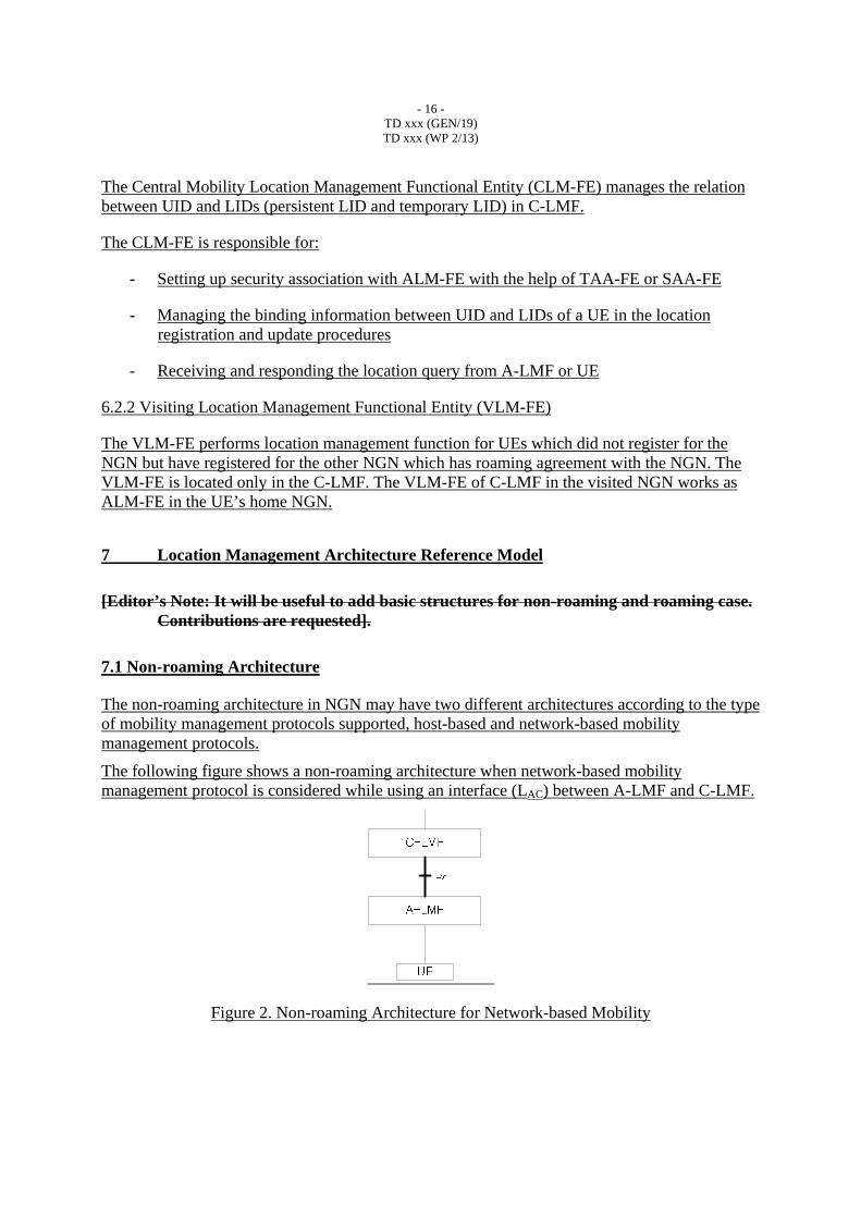
7.1 Non-roaming Architecture
The non-roaming architecture in NGN may have two different architectures according to the type of mobility management protocols supported, host-based and network-based mobility management protocols.
The following figure shows a non-roaming architecture when network-based mobility management protocol is considered while using an interface (LAC) between A-LMF and C-LMF.
Figure 2. Non-roaming Architecture for Network-based Mobility
- 17 - TD xxx (GEN/19) TD xxx (WP 2/13)
The following figure shows a non-roaming architecture when host-based mobility management protocol is considered while using a direct interface (LUC) between UE and C-LMF.
Figure 3. Non-roaming Architecture for Host-based Mobility
The following figure shows a non-roaming architecture when host-based mobility management protocol is considered while using an interface (LUA) between UE and A-LMF and an interface (LAC) between A-LMF and C-LMF.
Figure 4. Non-roaming Architecture for Host-based Mobility using
7.2 Roaming Architecture
The roaming architecture in NGN may also have two different architectures according to the type of mobility management protocols supported, host-based and network-based mobility management protocols. In addition, each of the mobility architecture may have different architectures according to which interfaces are used among UE, A-LMF, and C-LMF.
The following figure shows a roaming architecture when network-based mobility management protocol is considered while using a direct interface (LAC) between A-LMF in visited NGN and C-LMF in home NGN.
- 18 - TD xxx (GEN/19) TD xxx (WP 2/13)
Figure 5. Roaming Architecture for Network-based Mobility using LAC
The following figure shows a roaming architecture when network-based mobility management protocol is considered while using interface (LAC) between A-LMF in visited NGN and C-LMF in the visited NGN and an interface (LCC) between C-LMF in the visited NGN and C-LMF in home NGN.
Figure 6. Roaming Architecture for Network-based Mobility using LAC and LCC
The following figure shows a roaming architecture when host-based mobility management protocol is considered while having a direct interface (LUC) between UE and C-LMF in home NGN.
- 19 - TD xxx (GEN/19) TD xxx (WP 2/13)
Figure 7 : Roaming Architecture for Host-based Mobility using LUC
The following figure shows a roaming architecture when network-based mobility management protocol is considered while having an interface (LUA) between UE and A-LMF in visited NGN and an interface (LAC) between the A-LMF in the visited NGN and C-LMF in home NGN.
Figure 8. Roaming Architecture for Host-based Mobility using LUA and LAC
The following figure shows a roaming architecture when host-based mobility management protocol is considered while having an interface (LUC) between UE and C-LMF in the visited NGN and an interface (LCC) between the C-LMF in the visited NGN and C-LMF in home NGN.
- 20 - TD xxx (GEN/19) TD xxx (WP 2/13)
UE
A-LMF
C-LMF
LCC
UE
A-LMF
C-LMF
Visited NGN Home NGN
LUC
Figure 9. Roaming Architecture for Host-based Mobility using LUC and LCC
The following figure shows a roaming architecture when network-based mobility management protocol is considered while having an interface (LUA) between UE and A-LMF in visited NGN, an interface (LAC) between the A-LMF in visited NGN and C-LMF in the visited NGN, and an interface (LCC) between the C-LMF in the visited NGN and C-LMF in home NGN.
Figure 10. Roaming Architecture for Host-based Mobility using LUA, LAC and LCC
6.2 Detailed Functional Architectures
[Editor’s Note: The description on detailed functional architecture is necessary. Contributions are solicited].
6.3 Relationship with NGN-FRA
[Contributions are invited. Some contents of Appendix III will be reflected in this section after consensus is made]
- 21 - TD xxx (GEN/19) TD xxx (WP 2/13)
78 Functional Information Flows
The functional flows of location management procedure are considered for non-roaming case and roaming case.
78.1 Non-roaming caseCase
The following figure shows the location management architecture in non-roaming case. In the mobile UE’s home network, ALM-FE and CLM-FE functions are deployed to manage UE’s status and location information.
Figure 11. Location Management Architecture in Non-roaming Case
A UE or ALM-FE starts location management procedure when it detects the attachment or location changes of UE in the network. There are two possible cases for starting location management procedure as follows.
Case 1) Network-based Location Management
The ALM-FE starts performing location management procedure by sending location management messages to CLM-FE in the home network.
Case 2) Host-based Location Management
1) UE starts performing location management procedure by sending location management messages to ALM-FE. Then the ALM-FE delivers the messages to CLM-FE.
2) UE starts performing location management procedure by sending location management messages to CLM-FE directly.
- 22 - TD xxx (GEN/19) TD xxx (WP 2/13)
After receiving the location management messages, the CLM-FE will deliver the location management message to deregister the location information which was registered to old ALM-FE.
8.1.1 Network-based Location Management
When an UE has established a connection to the access network of the home network, the ALM-FE detecting the UE’s access performs the location registration and update procedures in the network-based location management architecture. By this, this information on mapping between user ID(UID) and location ID(LID) will be recorded and managed by associated LMFs.
As a UE moves from an access network to another in the same home network, new ALM-FE performs location management with CLM-FE. The CLM-FE sends the location management messages to deregister the UE’s location to the old ALM-FE.
For user data transport, the ALM-FE in which correspondent UE is connected will perform the location query operations to identify the location of the mobile UE.
The network-based location management architecture for mobile UEs and a correspondent UE within home network is shown in Fig x.
Figure 12. Network-based Location Management Architecture for UEs within Home Network
The following figure 13 shows the signaling flow for the network-based location management procedure of a mobile UE and a correspondent UE in a home network.
After the UE has attached to the home network (AN1), the ALM-FE1 sensing the attachment registers UE’s LID with the CLM-FE by sending location registration message. When the CLM-FE receives the location registration message from the ALM-FE1, it will also add the associated location information into the location database (or user profile server) for the UE. On the successful processing of the location database, the CLM-FE will respond with a location registration response message to the ALM-FE1.
For the purpose of transferring data packet from correspondent UE to UE in AN1, the ALM-FE to which the correspondent UE is connected will perform the location query operations to identify the location of the mobile UE. The rectangular box in the following figure is used to
- 23 - TD xxx (GEN/19) TD xxx (WP 2/13)
imply that the correspondent UE may be attached to any networks. Any LM functions in the networks are involved in exchanging the location query and response messages with the CLM-FE.
After the initial location registration, the UE may move around in the network. When the UE moves into the other access network (AN2) and the UE’s LID may be changed, the ALM-FE2 will perform the location update operations in the network-based location management procedure. In this case, the ALM-FE2 sensing the access updates UE’s LID with the CLM-FE by sending location update message, as shown in the figure below. When the CLM-FE receives the location update message from the ALM-FE2, it will also update the associated location information into the location database (or user profile server) for the UE. On the successful processing of the location database, the CLM-FE will respond with a location update response message to the ALM-FE2. Moreover the CLM-FE may send location management messages to deregister the UE’s location to the ALM-FE1.
The handover procedure which is related to location management function will be described in the Recommendation Q.HCF.
Figure 13. Network-based Location Management Procedure for Mobile UEs and correspondent UE within Home Network
8.1.2 Host-based Location Management
The host-based location management procedure is almost the same as the network-based location management. The only difference is that UE itself starts the location management process rather than A-LMF.
UE sends location management messages to ALM-FE and the ALM-FE sends the messages to CLM-FE. The ALM-FE may not be used depending on the mobility management protocols by making UE send the location management messages directly to the CLM-FE.
- 24 - TD xxx (GEN/19) TD xxx (WP 2/13)
Figure 14. Host-based Location Management Architecture for Mobile UEs within Home Network
The following figure shows the signaling flow for the location management procedure of a mobile UE in a home network. Note that ALM-FE may be involved between UE and CLM-FE.
After the UE has attached to the network, the UE registers UE’s persistent LID and temporary LID to the CLM-FE by sending location registration message. When the CLM-FE receives the location registration message from the UE, it will respond with a location registration response message to the UE.
If there is a mobile UE who wants to communicate with the other UEs, they may perform location query procedure to find the temporary location of the UEs. However, if the mobile UE only knows persistent LID and the UE does not perform the location query procedure. The UE may send the data packets to the persistent location of the other UEs.
After the initial location registration, the UE may move around in the network. When the UE moves into the other access network and the UE’s temporary LID may be changed, the UE will perform the location update operations. In this case, the UE updates UE’s temporary LID to the CLM-FE by sending location update message. The CLM-FE will respond with a location update response message to the UE.
With all this location management procedures, ALM-FE and CLM-FE may interoperate with HCF functional entities to setup tunnel for data transfer. The details for the tunnel setup are shown in the Q.HCF Recommendation.
- 25 - TD xxx (GEN/19) TD xxx (WP 2/13)
ALM-FE1(Home Network)
CLM-FE1(Home Network)
ALM-FE2(Home Network)
UE B
Initial Registration
Location Query
Location Update
UE A
Figure 15. Host-based Location Management Procedure for Mobile UEs within Home Network
78.2 Roaming caseCase
The following figure shows the location management architecture in roaming case for NGN. In the mobile UE’s home network and visited network, C-LMF and A-LMF functions are deployed to manage user’s location information. The visitor location management functional entity (VLM-FE) defined in C-LMF performs location management function for UEs in the visited network.
- 26 - TD xxx (GEN/19) TD xxx (WP 2/13)
Figure 16. Location Management Architecture in Roaming Case
A visiting UE or A-LMF starts location management procedure when it detects the location changes of UE in the network. There are two possible cases for starting location management procedure as follows.
Case 1) Network-based Location Management
� C-LMF in visited NGN is involved in location management
The ALM-FE starts performing location management procedure by sending location management messages to VLM-FE in visited C-LMF.
� C-LMF in visited NGN is not involved in location management
The ALM-FE starts performing location management procedure by sending location management messages to home CLM-FE.
Case 2) Host-based Location Management
UE
UE
C
- LMF
A
-
LMF
Home Network
A - LMF
...
Visited Network
C
-
LMF
A - LMF
A
-
LMF
...
control
- 27 - TD xxx (GEN/19) TD xxx (WP 2/13)
� C-LMF in visited NGN is involved in location management
- UE starts performing location management procedure by sending location management messages to visited ALM-FE. Then the ALM-FE delivers the messages to VLM-FE in visited C-LMF and then the VLM-FE delivers the messages to home CLM-FE.
- UE starts performing location management procedure by sending location management messages to VLM-FE in visited C-LMF and then the VLM-FE delivers the location messages to home CLM-FE.
� C-LMF in visited NGN is not involved in location management
UE starts performing location management procedure by sending location management messages to home CLM-FE.
After receiving the location management messages, the CLM-FE will deliver the location management message to deregister the location information which was registered to ALM-FE.
8.2.1 Network-based Location Management
8.2.1.1 Location Management without C-LMF Involvement
The ALM-FE detects location changes of UE and then the ALM-FE sends the location management messages to the CLM-FE in the home network. The location management procedure between ALM-FE in the visited network and CLM-FE in the home network is the same as the one between ALM-FE and CLM-FE in the non-roaming case in the home network.
8.2.1.1.1 Location Management for Roaming UEs between Home and Visited Networks
As a UE moves from its home network to a visited network, the ALM-FE in the visited network performs location management with CLM-FE in home network. The CLM-FE in home network updates the UE’s new location information and then sends location management messages to deregister the UE’s location in the A-LMF of the home network.
- 28 - TD xxx (GEN/19) TD xxx (WP 2/13)
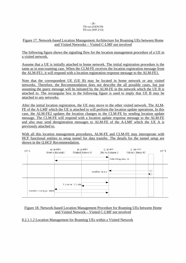
Figure 17. Network-based Location Management Architecture for Roaming UEs between Home and Visited Networks – Visited C-LMF not involved
The following figure shows the signaling flow for the location management procedure of a UE in a visited network.
Assume that a UE is initially attached to home network. The initial registration procedure is the same as in non-roaming case. When the CLM-FE receives the location registration message from the ALM-FE1, it will respond with a location registration response message to the ALM-FE1.
Note that the correspondent UE (UE B) may be located in home network or any visited networks. Therefore, the Recommendation does not describe the all possible cases, but just assuming the query message will be initiated by the ALM-FE in the network which the UE B is attached to. The rectangular box in the following figure is used to imply that UE B may be attached to any networks.
After the initial location registration, the UE may move to the other visited network. The ALM-FE of the A-LMF which the UE is attached to will perform the location update operations. In this case, the ALM-FE2 updates the location changes to the CLM-FE by sending location update message. The CLM-FE will respond with a location update response message to the ALM-FE and also may send deregistration messages to ALM-FE of the A-LMF which the UE A is previously attached to.
With all this location management procedures, ALM-FE and CLM-FE may interoperate with HCF functional entities to setup tunnel for data transfer. The details for the tunnel setup are shown in the Q.HCF Recommendation.
Figure 18. Network-based Location Management Procedure for Roaming UEs between Home and Visited Network – Visited C-LMF not involved
8.2.1.1.2 Location Management for Roaming UEs within a Visited Network
- 29 - TD xxx (GEN/19) TD xxx (WP 2/13)
After updating the location information in the visited network, UE may move within the visited network. The subsequent location updates in the same visited network do not trigger any location management signaling between the two C-LMFs of the visited network and the home network. As the UE moves from one access network to another, a new A-LMF may update the UE’s location with the VLM-FE, and then the VLM-FE deregisters the UE’s location with the old A-LMF.
Figure 19. Network-based Location Management Architecture for Roaming UEs within a Visited Network – Visited C-LMF not involved
The following figure shows the signaling flow for location management of a UE that moves from one access network to another within a visited network. Since the C-LMF in visited network is not involved, the basic procedure is the same as the procedure for roaming between home network and visited network.
ALM-FE1(Visited Network)
CLM-FE1(Home Network)
ALM-FE2(Visited Network)
UE ACLM-FE2
(Visited Network)
Location Update
Location deregistration
UE B
Initial Registration
Location Query
Figure 20. Network-based Location Management Procedure for Roaming UEs within a Visited Network – Visited C-LMF not involved
8.2.1.1.3 Location Management for Roaming UEs between Visited Networks
- 30 - TD xxx (GEN/19) TD xxx (WP 2/13)
As UE moves from one visited network to another, an A-LMF in the newly visited network performs location update with the CLM-FE in the home network. The CLM-FE may send deregistration message to the old A-LMF in the old visited network.
Figure 21. Network-based Location Management Architecture for Roaming UEs between Visited Networks – Visited C-LMF not involved
The following figure shows the signaling flow for the location management of a visiting UE in the newly visited network. The UE’s new ALM-FE updates the UE’s location with the CLM-FE of the UE’s home network. The C-LMF may send deregistration message to the A-LMF of the old visited network.
- 31 - TD xxx (GEN/19) TD xxx (WP 2/13)
Figure 22. Network-based Location Management Procedure for Roaming UEs between Visited Networks – Visited C-LMF not involved
8.2.1.2 Location Management with C-LMF Involvement
The ALM-FE detects location changes of UE and then the ALM-FE sends the location management messages to the VLM-FE of C-LMF in the visited network. The VLM-FE delivers the messages to the home CLM-FE to report that the UE is currently attached to the visited network. From the view point of the home CLM-FE, the VLM-FE can be considered as another ALM-FE. The VLM-FE handles all the subsequent location management messages from UE while the UE is in the visited network. The VLM-FE handles the location update procedure locally in the visited network; therefore, there is no need for inter-CN signaling between the two C-LMFs as long as the UE moves within the visited network. The location management procedure between ALM-FE and VLM-FE in the visited network is the same as the one between ALM-FE and CLM-FE in the non-roaming case in the home network.
7.2.1 Host-based LM in the roaming case
7.2.2 Network-based LM in the roaming case
Following figure shows inter-CN location management architecture for NGN. In the mobile user’s home network and the visited network, C-LMF and A-LMF functions are deployed to manage user’s location information. The visitor location management function (V-LMF) defined as a sub-function of C-LMF performs location management function for UEs in the visited network.
When a UE moves into the visited network, the UE performs location registration with an A-LMF in the visited network. The A-LMF receives the location registration message from the visiting UE, and then the A-LMF forwards the messages to the C-LMF of the visited network. As the C-LMF receives the location registration message, the V-LMF downloads the subscriber information from the C-LMF of the UE’s home network. The V-LMF reports to the C-LMF of the UE’s home network that the UE is currently attached to the visited network. From the view point of the C-LMF in the home network, the V-LMF can be considered as another A-LMF. The V-LMF handles all the subsequent location update messages from UE while the UE is in the visited network. The V-LMF handles the location update procedure locally; therefore, there is no need for inter-CN signaling between the two C-LMFs as long as the UE moves within the visited network. From the viewpoint of the C-LMF at the home network, the V-LMF is considered as an A-LMF. The location registration procedure between A-LMF and V-LMF in the visited network is same as the one between A-LMF and C-LMF in the home network. The location registration procedure used between the V-LMF of a visited network and the C-LMF of a home network is same as that between a typical A-LMF and a C-LMF except for additional subscriber information transfer for Inter-CN roaming.
[Editor’s Note: It is pointed that 3GPP does not allow the download of subscribing information between operators. Further discussion between related groups and further contributions are requested to clarify the issue] .
7.2.2.1 Inter-CN Location Management Scenario
78.2.2.1.2.1.1 Location Management for Roaming UEs between Home and Visited NetworksRoaming from Home Network to Visited Network
- 33 - TD xxx (GEN/19) TD xxx (WP 2/13)
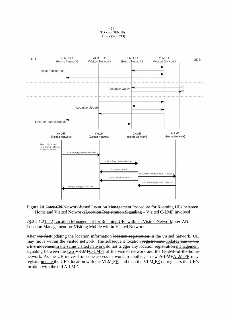
As a UE moves from its home network to a visited network, the ALM-FE inan A-LMF in the visited network performs location registration management with VLM-FE function withinin the visited C-LMF of the visited network. The VLM-FE registers updates the UE’s location with the CLM-FE in theC-LMF in the UE’s home network. During the location registration process, the user’s subscription information is passed from the C-LMF of the home network to the V-LMF. At the end of the location registration, tThe C-LMFCLM-FE in the home network de-registers the UE’s location with the A-LMF of the home network.
Visited Network
A-LMF
Home Network
. . .A-LMF
C-LMF
A-LMF. . .A-LMF
C-LMF(V-LMF)
UELocation Update
Subscription Information
De-registration
UE
Figure 23. Network-based Location Management Architecture for Roaming UEs between Home and Visited Networks – Visited C-LMFInter-CN Location Registration involved
The fFollowing figure shows the signaling flow for the first location registration location management procedure of a UE in a visited network. The location registration procedure between A-LMF and V-LMF is same as the location registration procedure between A-LMF and C-LMF. Likewise, the location registration procedure between V-LMF of the visited network and a C-LMF of the home network is same as the location registration procedure between A-LMF and C-LMF. The V-LMF may request user’s subscription information from the C-LMF of the home network, and then the C-LMF sends deregistration message to the A-LMF in the home network.
- 34 - TD xxx (GEN/19) TD xxx (WP 2/13)
ALM-FE1(Home Network)
CLM-FE1(Home Network)
ALM-FE2(Visited Network)
VLM-FE(Visited Network)
Location Update
Location deregistration
UE B
Initial Registration
Location Query
UE A
A-LMF(Visited Network)
V-LMF(Visited Network)
C-LMF(Home Network)
Event: UE moves from Home Networkto Visited Network
Location Registration Request
Location Registration Request
Location Registration Ack.
Location Registration Ack.
Subscription Info
A-LMF(Home Network)
Location De-registration Indication
Location De-registration Confirm
Figure 24. Inter-CN Network-based Location Management Procedure for Roaming UEs between Home and Visited NetworksLocation Registration Signaling – Visited C-LMF involved
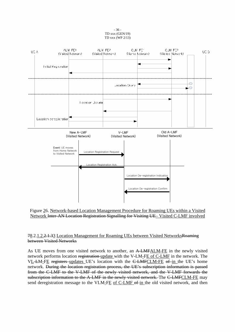
78.2.2.1.21.2.2 Location Management for Roaming UEs within a Visited NetworkInter-AN Location Management for Visiting Mobile within Visited Network
After the firstupdating the location information location registration in the visited network, UE may move within the visited network. The subsequent location registrations updates due to the UE’s movementin the same visited network do not trigger any location registration management signaling between the two V-LMFC-LMFs of the visited network and the C-LMF of the home network. As the UE moves from one access network to another, a new A-LMFALM-FE may register update the UE’s location with the VLM-FE, and then the VLM-FE de-registers the UE’s location with the old A-LMF.
- 35 - TD xxx (GEN/19) TD xxx (WP 2/13)
Visited Network
A-LMF
Home Network
. . .A-LMF
C-LMF
A-LMF . . .A-LMF
C-LMF(V-LMF)
Location Update
De-registration
UEUE
Figure 25. Network-based Location Management Architecture for Roaming UEs within a Visited NetworkInter-AN Location Registration for Visiting UE – Visited C-LMF involved
Figure 26 shows the signaling flow for location registration management of a UE that moves from one access network to another within the a visited network. The UE’s new A-LMF registers updates the UE’s location with the VLM-FE of the C-LMF in the visited network, . The location registration procedure between the A-LMF and the V-LMF is same as the location registration procedure between the A-LMF and its corresponding C-LMF. The A-LMF may download user profile information from the V-LMF, and then the VLM-FE decides that the old A-LMF is located in the same network and just sends deregistration message to the old A-LMF.
- 36 - TD xxx (GEN/19) TD xxx (WP 2/13)
New A-LMF(Visited Network)
V-LMF(Visited Network)
Location Registration Request
Location Registration Ack.
Old A-LMF(Visited Network)
Location De-registration Indication
Location De-registration Confirm
Event: UE moves from Home Networkto Visited Network
Figure 26. Network-based Location Management Procedure for Roaming UEs within a Visited Network Inter-AN Location Registration Signalling for Visiting UE– Visited C-LMF involved
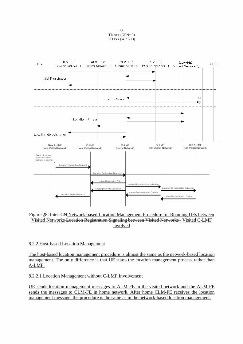
78.2.1.2.2.1.33 Location Management for Roaming UEs between Visited NetworksRoaming between Visited Networks
As UE moves from one visited network to another, an A-LMFALM-FE in the newly visited network performs location registration update with the V-LM-FE of C-LMF in the network. The VL-LM-FE registers updates UE’s location with the C-LMFCLM-FE of in the UE’s home network. During the location registration process, the UE’s subscription information is passed from the C-LMF to the V-LMF of the newly visited network, and the V-LMF forwards the subscription information to the A-LMF in the newly visited network. The C-LMFCLM-FE may send deregistration message to the VLM-FE of C-LMF of in the old visited network, and then
- 37 - TD xxx (GEN/19) TD xxx (WP 2/13)
the V-LM-FE de-registers the UE’s location with the old ALM-FEold A-LMF in the old visited network.
Old Visited Network
A-LMF
Home Network
. . .A-LMF
C-LMF
A-LMF. . .A-LMF
C-LMF(V-LMF)
New Visited Network
A-LMF. . .A-LMF
C-LMF(V-LMF)
Location Update
Subscription Information
De-registration
UEUE
Figure 27. Network-based Location Management Architecture for Roaming UEs between Visited Networks Inter-CN Location Registration between Visited Networks– Visited C-LMF
involved
Figure 28 shows the signaling flow for the first location registration management of a visiting UE in the newly visited network. The UE’s new A-LMFALM-FE registers updates the UE’s location with the V-LM-FE of C-LMF in the network, and the V-LM-FE registers updates the UE’s location with the C-LMFCLM-FE of in the UE’s home network. The location registration procedure between the A-LMF and the V-LMF is same as one described in Section 7.2.2.1.2. The CLM-FE of the C-LMF may send deregistration message to the V-LM-FE in the old visited network, and then the V-LM-FE forwards the deregistration message to the ALM-FEA-LMF of in the old visited network.
- 38 - TD xxx (GEN/19) TD xxx (WP 2/13)
New A-LMF(New Visited Network)
V-LMF(New Visited Network)
C-LMF(Home Network)
Location Registration Request
Location Registration Request
Location Registration Ack.
Location Registration Ack.
Subscription Info Download
V-LMF(Old Visited Network)
Location De-registration Indication
Location De-registration Confirm
Old A-LMF(Old Visited Network)
Location De-registration Indication
Location De-registration Confirm
Event: UE moves from one Visited Network to another
Figure 28. Inter-CN Network-based Location Management Procedure for Roaming UEs between Visited Networks Location Registration Signaling between Visited Networks– Visited C-LMF
involved
8.2.2 Host-based Location Management
The host-based location management procedure is almost the same as the network-based location management. The only difference is that UE starts the location management process rather than A-LMF.
8.2.2.1 Location Management without C-LMF Involvement
UE sends location management messages to ALM-FE in the visited network and the ALM-FE sends the messages to CLM-FE in home network. After home CLM-FE receives the location management message, the procedure is the same as in the network-based location management.
- 39 - TD xxx (GEN/19) TD xxx (WP 2/13)
8.2.2.1.1 Location Management for Roaming UEs between Home and Visited Networks
As a UE moves from its home network to a visited network, UE starts location management procedure by sending messages to the ALM-FE in the visited network. Then the ALM-FE sends the messages to home CLM-FE in the home C-LMF. After that, the procedure is the same as in network-based location management procedure.
A-LMF A-LMF
C-LMF
... A-LMFA-LMF
C-LMF
...
UE UE
Home Network Visited Network
Location RegistrationLocation Update
Figure 29. Host-Based Location Management Architecture for Roaming UEs between Home and Visited Networks – Visited C-LMF not involved
The following figure shows the signaling flow for the location management procedure of a UE in a visited network. Note that UE may send location management messages directly to CLM-FE depending on the mobility management protocols.
Figure 30. Host-Based Location Management Procedure for Roaming UEs between Home and Visited Network – Visited C-LMF not involved
8.2.2.1.2 Location Management for Roaming UEs within a Visited Network
After once moving into the visited network from home network, UE may move within the visited network. UE sends location management messages to the new ALM-FE. The ALM-FE sends the messages to home CLM-FE. After that, the procedure is the same as in network-based location management procedure.
- 40 - TD xxx (GEN/19) TD xxx (WP 2/13)
A-LMF A-LMF
C-LMF
... A-LMFA-LMF
C-LMF
...
UE UE
Home Network Visited Network
Location RegistrationLocation Update
Figure 31. Host-Based Location Management Architecture for Roaming UEs within a Visited Network – Visited C-LMF not involved
The following figure shows the signaling flow for location management of a UE that moves from one access network to another within a visited network. Note that UE may send location management messages directly to CLM-FE depending on the mobility management protocols.
Figure 32. Host-Based Location Management Procedure for Roaming UEs within a Visited Network – Visited C-LMF not involved
8.2.2.1.3 Location Management for Roaming UEs between Visited Networks
As UE moves from one visited network to another, the UE start location management process by sending location management messages to ALM-FE in the newly visited network. The ALM-FE sends the messages to CLM-FE in the home network. After that, the procedure is the same as in network-based location management procedure.
- 41 - TD xxx (GEN/19) TD xxx (WP 2/13)
A-LMF A-LMF
C-LMF
...
A-LMFA-LMF
C-LMF
...
UE
UE
Home Network
New Visited Network
A-LMFA-LMF
C-LMF
...
Old Visited Network
Location UpdateLocation Registration
Figure 33. Host-Based Location Management Architecture for Roaming UEs between Visited Networks – Visited C-LMF not involved
The following figure shows the signaling flow for the location management of a visiting UE in the newly visited network. Note that UE may send location management messages directly to CLM-FE depending on the mobility management protocols.
Figure 34. Host-Based Location Management Procedure for Roaming UEs between Visited Networks – Visited C-LMF not involved
8.2.2.2 Location Management with C-LMF Involvement
- 42 - TD xxx (GEN/19) TD xxx (WP 2/13)
UE sends location management messages to ALM-FE in the visited network and the ALM-FE sends the messages to VLM-FE of C-LMF in visited network. The A-LMF in the visited network may not be used depending on the mobility management protocols. Therefore, UE may send the location management messages directly to the VLM-FE of C-LMF in the visited network. After VLM-FE in the visited C-LMF receives the location management message, the procedure is the same as in the network-based location management.
8.2.2.2.1 Location Management for Roaming UEs between Home and Visited Networks
As a UE moves from its home network to a visited network, UE start location management procedure by sending messages to the ALM-FE in the visited network. Then the ALM-FE sends the messages to VLM-FE in the visited C-LMF. The VLM-FE updates the UE’s location with the CLM-FE in the UE’s home network. The CLM-FE in the home network deregisters the UE’s location with the A-LMF of the home network.
A-LMF A-LMF
C-LMF
... A-LMFA-LMF
C-LMF
...
UE UE
Home Network Visited Network
Location UpdateLocation Registration
Figure 35. Host-Based Location Management Architecture for Roaming UEs between Home and Visited Networks – Visited C-LMF involved
The following figure shows the signaling flow for the location management procedure of a UE in a visited network. Note that UE may send location management messages directly to VLM-FE of C-LMF depending on the mobility management protocols.
- 43 - TD xxx (GEN/19) TD xxx (WP 2/13)
Figure 36. Host-Based Location Management Procedure for Roaming UEs between Home and Visited Networks – Visited C-LMF involved
8.2.2.2.2 Location Management for Roaming UEs within a Visited Network
After once moving into the visited network from home network, UE may move within the visited network. UE sends location management messages to the new ALM-FE. The ALM-FE sends the messages to CLM-FE in home network. After that, the procedure is the same as in network-based location management procedure.
Figure 37. Host-Based Location Management Architecture for Roaming UEs within a Visited Network – Visited C-LMF involved
The following figure shows the signaling flow for location management of a UE that moves from one access network to another within a visited network. Note that UE may send location management messages directly to VLM-FE of C-LMF depending on the mobility management protocols.
- 44 - TD xxx (GEN/19) TD xxx (WP 2/13)
Figure 38. Host-Based Location Management Procedure for Roaming UEs within a Visited Network – Visited C-LMF involved
8.2.2.2.3 Location Management for Roaming UEs between Visited Networks
As UE moves from one visited network to another, the UE start location management process by sending location management messages to ALM-FE in the newly visited network. The ALM-FE sends the messages to VLM-FE of C-LMF in the newly visited network. After that, the procedure is the same as in network-based location management procedure.
A-LMF A-LMF
C-LMF
...
A-LMFA-LMF
C-LMF
...
UE
UE
Home Network
New Visited Network
A-LMFA-LMF
C-LMF
...
Old Visited Network
Location UpdateLocation Registration
- 45 - TD xxx (GEN/19) TD xxx (WP 2/13)
Figure 39. Host-Based Location Management Architecture for Roaming UEs between Visited Networks – Visited C-LMF involved
The following figure shows the signaling flow for the location management of a visiting UE in the newly visited network. Note that UE may send location management messages directly to VLM-FE of C-LMF depending on the mobility management protocols.
Figure 40. Host-Based Location Management Procedure for Roaming UEs between Visited Networks– Visited C-LMF involved
- 46 - TD xxx (GEN/19) TD xxx (WP 2/13)
- 47 - TD xxx (GEN/19) TD xxx (WP 2/13)
Appendixes
Appendix I. Usage Models
[Editor’s Note: this section will describe how some of the candidate IP-based protocols could be used for location management and what are needed for it, based on the LMF identified in this Recommendation. Some reference texts are given below. Further contributions are invited].
1. SIP based Location Management
[Editor’s Note: In NGN, SIP is likely to be used in the form of IMS. In this case, this section may be changed into “IMS for Location Management”. Further contributions are invited]
The Session Initiation Protocol (SIP) has been specified in the IETF for supporting the control of IP-based multimedia sessions as a signaling protocol. The SIP is an application-layer control protocol that can establish, modify, and terminate multimedia sessions. The SIP functional entities include UA, Proxy Server, Redirect Server, Registrar and the location DB. It operates independently of the underlying transport layer protocols such as Transmission Control Protocol (TCP), User Datagram Protocol (UDP) and Stream Control Transmission Protocol (SCTP). More details on SIP are given in IETF RFC 3261.
1.1 Location Update
SIP provides the location registration and update functionality using the SIP Registrar. When an UE moves into a new network region, it registers its current location ID (SIP URI) with the location database via a SIP Registrar.
Figure 1-1 shows the functional information flows for the SIP-based location registration and update operations.
User ID (SIP URI),Location ID (IP address)
ARMT(SIP) SIP Registrar (location DB)
LU (SIP REGISTER)
LU-ACK (SIP OK)
- 48 - TD xxx (GEN/19) TD xxx (WP 2/13)
Figure I-1. SIP-based Location Update
As shown in the figure, each time an UE gets a new location ID (IP address) from the new AR region, it will update its location with the SIP Registrar server by sending the SIP REGISTER request message. In response to the REGISTER message, the Registrar will send an SIP status message (e.g., 200 OK) to the UE.
1.2 Location Query and Session Establishment
SIP also provides the location query functionality for call/session establishment using the SIP Proxy or Redirect servers. It is noted in SIP that the session establishment could be done at the same time with the location query operations, in particular, in case of using SIP proxy server instead of SIP redirect server.
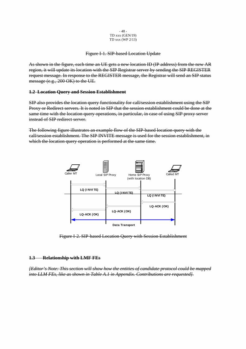
The following figure illustrates an example flow of the SIP-based location query with the call/session establishment. The SIP INVITE message is used for the session establishment, in which the location query operation is performed at the same time.
Local SIP ProxyCaller MT Home SIP Proxy(with location DB)
LQ (INVITE)
Called MT
LQ (INVITE)LQ (INVITE)
LQ-ACK (OK)
LQ-ACK (OK)LQ-ACK (OK)
Data Transport
Figure I-2. SIP-based Location Query with Session Establishment
1.3 Relationship with LMF FEs
[Editor’s Note: This section will show how the entities of candidate protocol could be mapped into LLM FEs, like as shown in Table A.1 in Appendix. Contributions are requested].
- 49 - TD xxx (GEN/19) TD xxx (WP 2/13)
12. MIP based Location Management
The Mobile IP (MIP) is an MM protocol that has been specified in the IETF. Mobile IP may be divided into Mobile IPv4 (MIPv4) and Mobile IPv6 (MIPv6). Details of MIPv4 and MIPv6 are described in IETF RFC 3344 and RFC 3775, respectively.
These two protocols basically provide similar functionality with some exceptions in the detailed operation mechanisms. In this section, the Mobile IPv4 is reviewed in terms of the LMF.
1
2.1 Location Update
When a UE moves into a new subnet, apart from the Home Network, it will get a CoA of FA (IP address of FA) in the new network. The UE may use a Co-located CoA (CCoA), which will be obtained by Dynamic Host Configuration Protocol (DHCP). In the process of obtaining the CoA address, the UE may be required for performing the appropriate authentication procedure via AAA server.
After realizing that the UE is in the new network, it registers with the HA with a Care of Address (CoA). The UE must register its CoA with the HA whenever the UE changes its subnet. This is called ‘Binding Update’ procedure in the MIP. It is noted that the MIP HA is used as an LM. That is, the HA maintains the location information for the UE. In this case, the Home Address (HoA) of the UE is used as the User or Terminal ID, whereas the CoA of FA will be used as the Location ID (IP address).
In this way, the HA maintains and updates the current location ID for the UE, as shown in the figure below.
User ID (HoA),Location ID (CoA)
FAMT HA
LU (BU)
LU-ACK (BU-ACK)
Figure I-31. Location Update by MIP
- 50 - TD xxx (GEN/19) TD xxx (WP 2/13)
21.2 Data Transport with Location Management
When an external Correspondent Host (CH) sends a data packet toward the UE (over the HoA of the UE), the HA will intercept and receive the packets destined for the UE from the CH, since the UE is roaming in a visited network.
The HA then forwards these packets to the UE using the CoA of UE. These data packets will be delivered to the UE through the Mobile IP tunnel. Basically, the MIP uses the standard IP routing scheme for the data transport.
When receiving the tunneled packets from the HA, the FA will de-capsulate the received packets and delivers the original packets to the UE, as shown in the figure below.
FAMT HA
LU (BU)
LU-ACK (BU-ACK)
CH
Data TransportTunneled DataData Transport
Figure I-42. Data Transport by MIP
2.3 Relationship with LMF FEs
- 51 - TD xxx (GEN/19) TD xxx (WP 2/13)
Appendix II. Examples of location IDs
[Editor’s Note: This section will describe examples of location ID. Contributions regarding other examples of location IDs are invited].
1. Location ID in GSM
In the GSM network the MT will connect to the network via Base station. The Location of MT about the Routing Area is stored in the HLR and SGSN which can be used for pagingincluding the cell identity that is defined in GSM networks. When the MT changes the RA, it will send this update to the new SGSNHLR and SGSN and will be updated with new information. The cell identity is store in SGSN when a L2 connection is established. When there is a L2 connection, and the serving cell has been changed, the renewal of the cell identity will be updated in SGSN. Here L2 location can be found by cell identity.
- 52 - TD xxx (GEN/19) TD xxx (WP 2/13)
Appendix III. Possible mappings to NGN FRA
[Editor’s Note: This section is not agreed but it is noted that it includes valuable information as a possible mapping to NGN FRA. Contributions to revise following figure and texts are invited. Also the contributions regarding other possible mapping are requested].
1. Option 1
As NGN terminal has mobility capability in nature, a conceptual model of MMCF should be gracefully mapped to existing NGN functional architecture.
Regarding NGN components, functional entities of MMCF can belong to IP multimedia service component or NACF component.
Figure III-1. Mapping to NGN components
SUP(Service User Profile)-FE(S-5) in IMS component provides the functions of LMF in Service Stratum with some extension. TLM(Transport Location Management)-FE(T-13) in NACF provides the functions of LMF in Transport Stratum with some extension. S-CSC(Serving Call Session Control)-FE(S-1), P-CSC(Proxy Call Session Control)-FE(S-2), I-CSC(Interrogating Call Session Control)-FE(S-3), and SL(Subscription Locator)-FE(S-4) in IMS component provide some part of functions of HCF in Service Stratum.
However, there exists no functional entity which can handle the handover or switch from old connection to new connection. In NACF a new functional entity, THC(Transport Handover Control)-FE, should be added. In IP multimedia service component a new functional entity, SHC(Service Handover Control)-FE, should be added. THC-FE controls the handover of inter-AN and intra-AN. SHC-FE controls the handover of inter-CN.
- 53 - TD xxx (GEN/19) TD xxx (WP 2/13)
Figure III-2 Functional Entities related to MM
2. Option 2
For relating LMF with NGN-FRA, there exist several cases. In the following table, each FE of applicability in Y.2012 is just mapped to the similar role of LMF, which should extend for supporting mobility.
Following Table summarizes the three cases of mapping between LMFs and NGN functional architecture.
Table III-1. Relationship between LMFs and NGN-FRA
Case A-LMF C-LMF Case1: NACF only
Access TLM-FE Core TLM-FE
Case2: SCF only
P-CSC-FE S-CSC-FE
- 54 - TD xxx (GEN/19) TD xxx (WP 2/13)
Case3: SCF+NACF
mixed Access TLM-FE
SC-FE
(new SCF FE or existed SCF FE)
The following figure illustrates the example mapping of LMF over the NACF.
Figure III-3. LMF functional mapping over NACF
The following figure illustrates the example mapping of LMF over the SCF.
- 55 - TD xxx (GEN/19) TD xxx (WP 2/13)
Figure III-4. LMF functional mapping over SCF
The following figure illustrates the example mapping of LMF over both SCF and NACF.
Figure III-5. LMF functional mapping over NACF and SCF