TelevisGo MANAGEMENT AND MONITORING Monitoring and control have never been this easy QUICK START TelevisGo is a family of devices used to monitor, control and manage commercial refrigeration installations from a distance. EN
Transcript
TelevisGo
MA
NA
GEM
ENT
AN
D M
ON
ITO
RIN
G
Monitoring and control have never been this easy
QUICKSTART
TelevisGo is a family of devices used to monitor, control and manage commercial refrigeration installations from a distance. EN
CONTENTS
1. INTRODUCTION ..................................................................................................... 31.1 INTRODUCTION ........................................................................................................................................................31.2 SYSTEM REQUIREMENTS ........................................................................................................................................3
2. MECHANICAL INSTALLATION ............................................................................... 42.1 GENERAL WARNINGS ..............................................................................................................................................42.2 PACKAGE CONTENTS ..............................................................................................................................................42.3 MECHANICAL INSTALLATION ................................................................................................................................42.4 CONNECTIONS ON THE DEVICE .........................................................................................................................4
3. INSTALLATION ....................................................................................................... 53.1 WEB INTERFACE ........................................................................................................................................................5
1.1 INTRODUCTIONThis guide contains all the general information needed for the installation and initial start-up of TelevisGo.For all other settings and options, see the full technical documentation available in electronic format (pdf) in TelevisGo or fromwww.eliwell.com subject to registration with the level1 restricted area.
You are urged to follow the instructions carefully to ensure that the installation and initial start-up of the software are done correctly.
1.2 SYSTEM REQUIREMENTSThe main technical features of TelevisGo are listed below:
• Power supply: DC12V with external 100-240 Va ±10%, 50-60 Hz supply• Max. power absorbed: 10 VA• Working temperature: 0 … 50°C• Storage temperature: -20 … 60°C• Operating/storage humidity: 10...90% (non condensing)• Maximum number of connectable devices: 224• Operating System: XP Embedded (English language)
(the license number card is inside the packaging)
• Connectivity: Ethernet (LAN), external GSM modem (RS232 interface based on SIEMENS type TC35 technology) and integrated USB ports
• Languages supported:• Italian• English• Spanish• German• French• Russian• Chinese
• Browsers supported:• Internet Explorer 7 or later• Mozilla Firefox 3.5 or later• Google Chrome 16.0.x or later
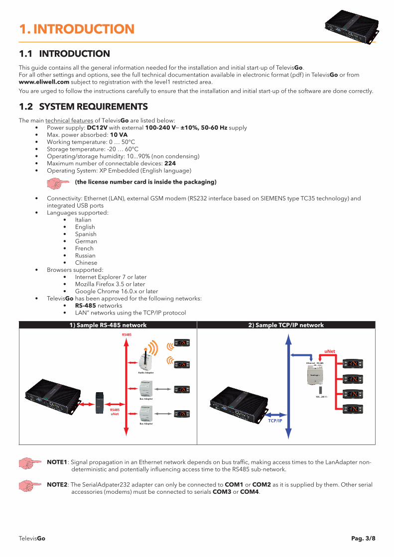
• TelevisGo has been approved for the following networks:• RS-485 networks• LAN” networks using the TCP/IP protocol
1) Sample RS-485 network 2) Sample TCP/IP network
Bus Adapter
Bus Adapter
Radio Adapter
RS485uNet
RS485
TCP/IP
100...240 V~
uNet
Ethernet RS-485
NOTE1: Signal propagation in an Ethernet network depends on bus traffic, making access times to the LanAdapter non-deterministic and potentially influencing access time to the RS485 sub-network.
NOTE2: The SerialAdpater232 adapter can only be connected to COM1 or COM2 as it is supplied by them. Other serial accessories (modems) must be connected to serials COM3 or COM4.
1. INTRODUCTION
TelevisGo Pag. 4/8
2.1 GENERAL WARNINGSIMPORTANT!Always make sure the device is switched OFF before touching connections.All operations must be carried out by qualified personnel.
Do not mount devices in extremely damp and/or dirt-laden areas; they are designed for use in places with ordinary or normal levels of contamination. Make sure the area near the cooling slots is ventilated.The admissible ambient temperature range for correct operation is between –5°C and +40°C.Modules and system devices must be connected using a cable with 0.5 mm2 conductors.There must be no more than 1.2 km between TelevisGo and the last module.Remember to insert a 120Ω, ¼W resistor between the “+” and “-“ terminals of the last device in the network.
NOTE: Comply with relevant applicable legislation when laying data transmission cables.
2.2 PACKAGE CONTENTSThe package contains:
• TelevisGo device• Power unit and power cable
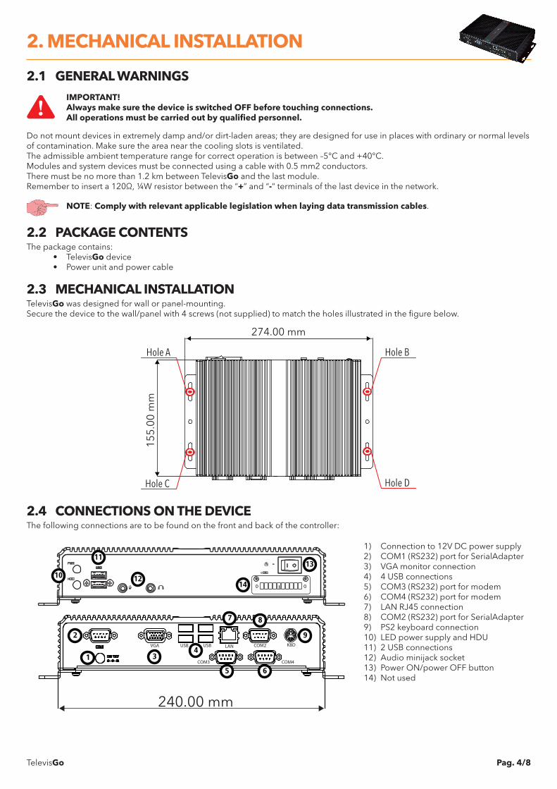
2.3 MECHANICAL INSTALLATIONTelevisGo was designed for wall or panel-mounting.Secure the device to the wall/panel with 4 screws (not supplied) to match the holes illustrated in the figure below.
274.00 mm
155.
00 m
m
Hole A
Hole C
Hole B
Hole D
2.4 CONNECTIONS ON THE DEVICEThe following connections are to be found on the front and back of the controller:
VGA USB USB
COM3
LAN COM2
COM4
KBD
240.00 mm
1
2
34
5 6
7 8
9
10
11
12
13
14
1) Connection to 12V DC power supply2) COM1 (RS232) port for SerialAdapter3) VGA monitor connection4) 4 USB connections5) COM3 (RS232) port for modem6) COM4 (RS232) port for modem7) LAN RJ45 connection8) COM2 (RS232) port for SerialAdapter9) PS2 keyboard connection10) LED power supply and HDU11) 2 USB connections12) Audio minijack socket13) Power ON/power OFF button14) Not used
2. MECHANICAL INSTALLATION
TelevisGo Pag. 5/8
To install TelevisGo, you have to set up the device and the network of devices it is connected to first.This can be done via the WEB interface.
NOTE1: Before scanning the network with TelevisGo, each device in the network must be assigned a unique address within the same serial port or LanAdapter, setting it based on the network used:
NOTE2: On plugging in, TelevisGo does not switch on immediately as some checks are run automatically and the software is loaded (takes about 30 seconds).
NOTE3: To switch the device off, press and hold button (13) for 4 seconds (a safety feature to prevent accidental switching off). In the event of a blackout, the PC and application restart automatically when mains power is returned.
3.1 WEB INTERFACETelevisGo must be switched on and connected to the internet to access the WEB interface.
Open a compatible browser and enter the device address:
http:// <TelevisGo IP Address>
The factory-set parameters are as follows: <TelevisGo IP Address> = 192.168.1.50 - Subnet mask:= 255.255.0.0
To assure the proper function of the PC - TelevisGo connection (Ethernet), the PC must have an IP address configured that is compatible with the TelevisGo subnet mask (normally the same Subnet mask and IP address, in which only the fourth numerical block changes to be different for each element in the network).For more detailed information and special installations, contact the network administrator.
When switched on, TelevisGo runs a system check then shows the login page (FIG.3).Set the language, and enter the default user profile (User Name: Administrator and Password: 0) and press Enter.The welcome page opens (FIG. 4).
FIG.3 FIG.4
User name:
Plant name:Televis Go
Versione 6.1.5
Password:
User interface language:
Save this info
English
Administrator
Login
TelevisGo
0
TelevisGo
Eliwell Controls
Software version: 6.1.5
Version (Upgrader): 6.1.5
Version (Database): 6.1.0.0
Interface identifier: 0
Page last update on: 7.39.34
Plant identification Found interfaces
Devices 15
Interface identifier: 999Devices 1
Device number: 16
60Maximum number of devices:
Televis Go
Informazioni
Data » Overview
Alarms ComputerSettingsToolsData
Overview Real time table Historical table Historical chart Energy report Energy chart
Welcome page
3.1.1 DEVICE SETTINGThe main settings are:
Date&Time: go to: Computer Information General (FIG.5)
Click Modify, setting Date&time then click Save.
Plant Name: go to: Computer Information General (FIG.5 - optional but recommended)
Click Modify, setting the Plant Name then click Save.
Network IP/DNS: go to: Computer Information Network Settings (FIG.6)
Click Modify, setting network IP/DNS (contact the network administrator) then click Save.
3. INSTALLATION
TelevisGo Pag. 6/8
FIG.5 FIG.6
Page last update on: 7.39.34
Computer » Information » General
Network settings General
General
Plant name
Date (yyyy-mm-dd)
Time (hh:mm)
Edit Save Cancel
2013
Eliwell Supermarket
10 17
7 57
Use client date/time
KEY: = Modify data;
= Save data;
= Cancel changes
Page last update on: 7.39.34
Computer » Information » Network settings
Alarms ComputerSettingsToolsData
General
Information Upgrade Reboot Update license Backup/Restore
Network settings
Edit Save Cancel
:
Proxy Settings
Proxy - SOCKS - Domain resolution
Proxy - Ignore for local addresses
Proxy - Enabled
Proxy - Protocol
Proxy - Server address
Proxy - Server port
Proxy - User
Proxy - Password
Native DNS
SOCKS 5
Activity logging
3.1.2 NETWORK SETTINGSThe following must be set:
Interfaces: go to: Settings Interfaces Scan
Now click Manage Interfaces ( ).In the window that opens, click Add ( ) and enter:
• Interface type: Serial Adapter (FIG. 7) or LanAdapter (FIG. 8)• Protocol: Micronet or Mixed (Micronet + Modbus)• Fieldbus: network types (BusAdapter, LanAdapter, LanAdapter Wifi, LANAdapter Radio +
RadioAdapter, RadioAdapter and SmartAdapter)• IP Address: enter the device IP address• Port: PC communication port used by the device
then click Save ( ).
Scan: go to: Settings Interfaces Scan
After setting the interfaces, set the scan range using pop up menus 1, 2, 3 and 4 (FIG.9).To start scanning network devices, click icon.On completion of the scan, a window opens listing all devices located (FIG.10).Line A identifies the network scanned. Line B and subsequent lines list devices associated to the network.New devices located are shown in green, existent ones are shown in white and devices which were not scanned and possibly no longer present are shown in grey.On completion, press Save to save all data logged.
FIG.7 FIG.9
Interfacetype
Fieldbus
Details
SerialAdapter
LanAdapter
Port
Protocol
BusAdapter
Micronet
COM1
Energy resourcesDevice templates
Page last update on: 7.39.34
Select all Deselect all Manage Interfaces
LAN Adapter
Interface ID Address Fieldbus Discovery range
0 192.168.0.1 From to00LanAdapter 00 14 14
NamingOut of networkDiscoveryView
1 2 3 4
FIG.8 FIG.10
Interfacetype
Fieldbus
Details
SerialAdapter
LanAdapter
Address
Port
Protocol
LanAdapter
Micronet
192 168 1 1
56789
LAN Adapter
Interface Interfaceidentifier DevicesAddress
0 192.168.0.1 1
Address Description State
New0 02:00 0.00:00 ID 974LX02:00
A
B
KEY:
= Add data; = Modify data;
= Save data; = Cancel changes
TelevisGo Pag. 7/8
Device Naming: go to: Settings Interfaces Naming (optional)For all devices in the network, you can set the following:
• A Long Name (Description)• A Short Name (You will need the “Short Name” to manage TXT messages)• A Delay in minutes (Temperature alarm indication delay).
You can also select the resources you want to monitor.NOTE: for further details, refer to the Manual (section entitled “Installation/Maintenance“)
Data-logging interval: go to: Settings Data Archive ControlOn opening this menu, click “Saved data-logging interval in archive”, then Modify ( ), enter a number (hours:minutes:seconds) and press Save ( ).The time set is the interval in which data from the selected resource will be logged.NOTE1: This interval does not apply to Statuses, Alarms and Digital Inputs. In these cases, only changes
in the variables themselves are recorded, and not in relation to the interval set.NOTE2: An interval cannot be set while data logging is underway.
Start data-logging: go to: Functions Start/StopFrom here you can Start/Stop logging data. Depending on whether data logging has started, press:
• Start (when Data Logging Status = Suspended)• Stop (when Data Logging Status = Underway).
Once data logging has started, you will be able to view the data captured and any alarms that have occurred.
4.1 RESPONSIBILITY AND RESIDUAL RISKSEliwell Controls srl declines any liability for damage due to:
• Unspecified installation/use and, in particular, in contravention of the safety requirements of established legislation or specified in this document.
• Use on equipment which does not provide adequate protection against electrocution, water and dust in the actual installation conditions;
• Use on equipment in which dangerous components can be accessed without the use of specific tools;• tampering with and/or modification of the product;• Installation/use on equipment which does not comply with established legislation and standards.
4.2 DISCLAIMERThis document is the exclusive property of Eliwell Controls srl and may not be reproduced or circulated unless expressly authorized by Eliwell Controls srl itself. Every care has been taken in preparing this document; however, Eliwell Controls srl cannot accept liability for any damage resulting from its use.The same applies to any person or company involved in preparing and editing this document. Eliwell Controls srl reserves the right to make changes or improvements at any time without notice.
4.3 DISPOSALThe appliance (or the product) must be disposed of separately in compliance with the local standards in force on waste disposal