© 2018 JETIR April 2018, Volume 5, Issue 4 www.jetir.org (ISSN-2349-5162)
JETIR1804263 Journal of Emerging Technologies and Innovative Research (JETIR) www.jetir.org 215
Temperature Sensor Interface with ARM Controller
LPC2148
Md. Moyeed Abrar Assistant Professor
Department of Computer Science &Engineering
Khaja Banda Nawaz of Engineering, Kalaburagi, Karnataka, India
Abstract: Microcontrollers are drawing tremendous attention worldwide owing to its rapidly increasing connections whether by Universal
serial bus (USB), Ethernet or wireless radio, and therefore the processing needed to support these communication channels. And one
more reason is the rapid growth and use of advanced peripherals. The ARM controllers are basically designed to target the 32 bit
Microcontroller. These processors provide excellent performance and are available with latest and enhanced features. The ARM
controllers are suitable for 32 bit embedded applications. The ARM 7 controller has been very successful in the current era of embedded
domain with partners such as NXP (Philips), Texas instruments, Atmel, and various other vendors delivering robust 32-bit
Microcontroller units (MCU). The ARM controllers are relatively easier to program and debug and delivers a higher processing
capability. The state of the art presented in this paper is the interfacing of temperature sensor with ARM controller LPC2148 and display
the temperature on the LCD. LM 35 series sensors are precision integrated sensors whose output voltage is linearly proportional to the
Celsius (centigrade) temperature. LM 335 temperature sensor is used in the system.
IndexTerms -Microcontrollers, embedded domain, ARM controllers, performance, interface, temperature sensor, LCD.
________________________________________________________________________________________________________
I. INTRODUCTION Signal conditioning is a term which is widely used in the world of data acquisition. In order to convert Physical quantities such as
temperature, light intensity, flow and speed to electrical signals, transducers are used. Based on the type of transducer, the output will be
produced in the form of voltage, current, charge, resistance, or capacitance. However these signals must be converted to voltage in order to
send input to an Analog to Digital converter (A to D converter). This conversion (modification) is commonly known as Signal conditioning.
Signal conditioning can be a current to voltage conversion or signal amplification. The transducer which is used to convert the temperature to
electrical signal in the form of voltage is known as thermistor. The thermistor responds to the temperature change by changing its resistance.
However the response is non- linear as depicted in table 1[1].
Table 1.Non linear response of thermistor with temperature
SL.NO TEMPERATURE (0C) THERMISTOR RESISTANCE
(KΩ)
1. 0 29.490
2. 25 10.000
3. 50 3.893
4. 75 1.700
5. 100 0.817
To write the software for such non-linear devices is quite cumbersome as there are many complexities associated. Hence in order to
overcome these problems linear temperature sensors used nowadays. The most common and widely used linear temperature sensors are
LM34, LM35, LM135, LM335 etc. In this paper the interfacing of Temperature Sensor with ARM controller LPC2148 is presented. The rest
of the paper is organized into sections as follows: section II includes the ARM controller LPC2148 overview. Section III focuses on the
system design. Results and discussion are reported in section IV. Finally section V summarizes the paper and presents the concluding
remark.
II. ARM CONTROLLER LPC2148 OVERVIEW
The essential features of the 16-bit/32-bit LPC2148 ARM controller are as follows
The LPC2148 from Philips is a 16-bit or a 32-bit Microcontroller that comes in a LQFP 64 pin package.
It has on chip static RAM of 40 KB and on chip flash memory of 512 KB. The interface/accelerator which is 128 bit wide
enables high speed 60 MHz operation.
The LPC2148 facilitates 100000 erase/write cycles and data detention is for duration of 20 years.
In-system programming (ISP)/In-application programming (IAP) is via on-chip boot loader software.
It takes 400ms for single flash sector or full chip erase and flash programming takes 1ms per 256-byte line.
Variable analog output is provided by a single 10-bit Digital to Analog converter (DAC).
Two 10-bit Analog to Digital converters (ADCs) provides a total of 14 analog inputs, with conversion times as low as 2.44µs per
channel.
USB 2.0 full speed compliant device controller with 2KB of end point RAM. Furthermore, the LPC2148 provides 8KB of on-
chip RAM accessible to USB by direct memory access (DMA).
Real time debugging with on-chip real monitor software and high speed real time tracing of instruction execution are offered by
Embedded ICE-RT and Embedded trace macro cell (ETM).
© 2018 JETIR April 2018, Volume 5, Issue 4 www.jetir.org (ISSN-2349-5162)
JETIR1804263 Journal of Emerging Technologies and Innovative Research (JETIR) www.jetir.org 216
Two 32-bit timers/External event counters (with four capture and four compare channels each), Pulse width modulation (PWM)
unit (six outputs) and a watchdog timer.
Low power real time clock (RTC) with independent power and a 32 KHz clock input.
Multiple serial interfaces including two UARTs (1665 equivalent), two fast 12C bus (400 Kbits/s), SPI and SSP with buffering
and variable data length capabilities [2].
III. SYSTEM DESIGN
3.1 The ARM-09 NXP LPC2148 Microcontroller Board Overview
The salient features of the Board are listed as follows
LPC2148 16/32 bit ARM7TDMI-S with 512K bytes program flash, 42K bytes RAM.
LCD 16x 2 alphanumeric display.
Stepper motor interface with direction and speed control.
Temperature sensor interface using internal DAC.
12 MHz crystal for easy communication set up.
External interrupt through key with LED indication.
Standard JTAG connector with ARM 2x10 pin layout for programming/debugging with ARM-JTAG.
Reset push button for resetting the controller.
Standard 26-pin FRC connectors to connect to on-board interface
Dip switch for enabling ISP.
One on board voltage regulator for generating 3.3V. Input to this will be from external +5V DC power supply through a 9-pin
DSUB connector.
One RS232 interface circuit with 9 pin DSUB connector, using UART0. This is used by the boot loader program to program the
LPC2148 flash memory without external programmer. User can also use this as other UART0 application program.
One RS232 interface circuit with 3 way male reliamate connector using UART1. This is used as additional UART to communicate
with external peripheral via serial communication interface.
The photographic view of the ARM-09 NXP LPC2148 Microcontroller Board is shown in fig.1
Fig.1Photographic view of the ARM-09 NXP LPC2148 Microcontroller Board
3.2 System Specifications
The System specifications are illustrated in table 2
Table 2. System specifications
SL.NO SPECIFICATIONS
1. Domain : Microprocessors and Microcontrollers,
Arm Controllers, Assembly language
programming
2. Arm controller: LPC2148 32-bit RISC
microcontroller from NXP founded by Philips.
3. Temperature Sensor: LM335A (3-pin)
4. Desktop computer: Dual core, 1GB RAM,
processor speed 2.5 GHz.
5. Port line: P0.25
6. Software: Keil µ vision-4
7. Serial communication: RS 232 cross cable
connections required for establishing
communication between the evaluation board
and a display terminal/host computer.
8. In-system Programming (ISP): Flash magic
software can be used to download the HEX files
to the flash magic of the controller.
9. Applications: Display of temperature on the
LCD.
© 2018 JETIR April 2018, Volume 5, Issue 4 www.jetir.org (ISSN-2349-5162)
JETIR1804263 Journal of Emerging Technologies and Innovative Research (JETIR) www.jetir.org 217
3.3 Temperature sensor interface
The LM335 series are precision, easily-calibrated, integrated circuit temperature sensors. Operating as a 2-terminal zener, the LM335 has a
breakdown voltage directly proportional to absolute temperature at +10 mV/°K. With less than 1Ω dynamic impedance the device operates
over a current range of 400 μA to 5 mA with virtually no change in performance [3]. The output voltage of LM335 are fed to controller using
internal ADC the channel used is ADC0.4 that convert the analog voltage into appropriate digital values. Using the converted digital value
the current temperature is calculated and displayed on to LCD screen. The circuit schematic for temperature sensor interface is illustrated in
fig.2
Fig.2 Temperature sensor interface schematic
The complete process of obtaining the temperature values on the LCD is illustrated by a flowchart as shown in fig.3
Fig.3 Flowchart
3.4 System Set up
The experimental set up was done in the Microprocessors laboratory. The system consists of a desktop computer, the ARM-09 NXP
LPC2148 Microcontroller board, adapter, USB cable and RS 232 cable. The personal computer was switched ON. The adapter was plugged
in the socket and the adapter pin was connected to the slot provided on the ARM-09 NXP LPC2148 Microcontroller board. The USB cable
was connected to the USB port of the desktop computer and the other end of the USB cable, that is, the male connector was connected to the
female connector of the RS232 cable and the male connector of the RS232 cable was connected to the female connector provided on the
ARM-09 NXP LPC2148 Microcontroller board. Fig.4 illustrates the photographic view of the system.
© 2018 JETIR April 2018, Volume 5, Issue 4 www.jetir.org (ISSN-2349-5162)
JETIR1804263 Journal of Emerging Technologies and Innovative Research (JETIR) www.jetir.org 218
Fig.4 Photographic view of the system
On the Desktop computer my computer icon was right clicked and manage option was chosen and further the device manager option was
selected and then the ports option was clicked which depicted the communication port as port 1 and the USB to serial port as port 3. The keil
µ-vision 4 software was used to write the C program for the display of temperature on the LCD screen located on the ARM-09 NXP
LPC2148 Microcontroller board. The following sequence of steps was followed in order to get the desired output. The keil µ-vision 4
software was opened by double clicking on the keil µ-vision 4 icon located on the PC screen [6]. The project option was right clicked and
then new µ-vision project was chosen as depicted in fig.5 Create New project window appears on the screen. A folder with the name
EXPERIMENT TEMPERATURE was created on the desktop and the file with name LM335 was saved in the folder Experiment LCD as
shown in fig.6 Another new window named Select Device for Target „Target 1‟appeared where the user has to select the ARM
microcontroller. The NXP series founded by Philips was chosen and in this category the LPC2148 was selected. The LPC2148 features were
displayed and OK option was clicked as illustrated in fig.7
Fig.5 Selecting new µ-vision project
Fig.6 Creation of folder and naming the file.
© 2018 JETIR April 2018, Volume 5, Issue 4 www.jetir.org (ISSN-2349-5162)
JETIR1804263 Journal of Emerging Technologies and Innovative Research (JETIR) www.jetir.org 219
Fig.7 Selecting the microcontroller LPC2148.
A new window appears named µ-vision copy start up project folder and Add file to the project with two options Yes and No. The Yes
option was chosen as depicted in fig.8
Fig.8 Selecting Yes option
In the project window Target was created as Target-1. The + sign of Target 1 was clicked as a result of which the source group-1 was
shown immediately below the Target-1. This is shown in fig.9
Fig.9 Creation of source group-1
After the creation of project, the file option was chosen and New was selected to open the editor window as shown in fig.10
Fig.10 Selecting the new file
© 2018 JETIR April 2018, Volume 5, Issue 4 www.jetir.org (ISSN-2349-5162)
JETIR1804263 Journal of Emerging Technologies and Innovative Research (JETIR) www.jetir.org 220
The program was written in embedded C language for the display of temperature on the LCD of ARM-09 NXP LPC2148 Microcontroller
board. After the completion of program the next step was to save the program. This is depicted in fig.11
Fig.11 Saving the program
As save icon was clicked a new window appears where the file name was given as EXCELLENT.C and the file was saved. The file
extension .C is mandatory. This is illustrated in fig.12
Fig.12 Naming the file as EXCELLENT.C
Colour syntax highlighting was enabled once the file EXCELLENT.C was saved as shown in fig.13
Fig.13 Colour syntax highlighting after saving the file
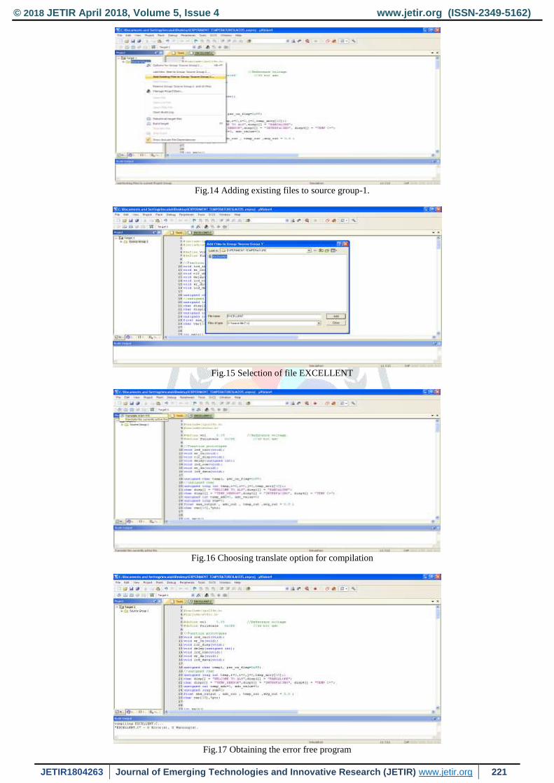
The source group 1 located below the Target 1 in the project window was right clicked and the option Add existing files in Group „Source
Group 1‟ was selected in order to add the .C source file to the group. After adding this source file this file was viewed in the project window.
This is illustrated in fig.14. A new window named Add Files to Group „Source Group 1‟ appeared where the file EXCELLENT was selected
and then Add and Close options were clicked sequentially as depicted in fig.15. The most important task was to compile the files. In order
for compilation the translate option was clicked as shown in fig.16. The build output window was checked where the message was displayed
as „EXCELLENT.C‟ 0 errors and 0 warnings, which ensured that the program was error free. This is illustrated in fig.17
© 2018 JETIR April 2018, Volume 5, Issue 4 www.jetir.org (ISSN-2349-5162)
JETIR1804263 Journal of Emerging Technologies and Innovative Research (JETIR) www.jetir.org 221
Fig.14 Adding existing files to source group-1.
Fig.15 Selection of file EXCELLENT
Fig.16 Choosing translate option for compilation
Fig.17 Obtaining the error free program
© 2018 JETIR April 2018, Volume 5, Issue 4 www.jetir.org (ISSN-2349-5162)
JETIR1804263 Journal of Emerging Technologies and Innovative Research (JETIR) www.jetir.org 222
In the project window Target-1 was right clicked and the options for Target, Target 1 was chosen as shown in fig.18
Fig.18 Choosing options for Target, Target-1
A new window appeared named options for Target „Target 1‟ where first Target option was selected. In this Target option the following were
selected Xtal 12.0 MHz; use Micro Lib, IROM (starting 0x0 size 0x80000) and IRAM 1(starting 0x40000000 size 0x8000). This is
illustrated in fig.19
Fig.19 Enabling Xtal, use Micro Lib, IROM and IRAM1
In the same window the next option chosen was output, where create hex file option was enabled by selecting it as shown in fig.20
Fig.20 Selecting create hex file option
Next in the same window linker option was chosen and here Use memory layout from Target Dialog was enabled by selecting it as illustrated
in fig.21
Fig.21 Enabling use memory layout from target dialog
© 2018 JETIR April 2018, Volume 5, Issue 4 www.jetir.org (ISSN-2349-5162)
JETIR1804263 Journal of Emerging Technologies and Innovative Research (JETIR) www.jetir.org 223
Finally, to come out of this window OK option was clicked. Lastly, Rebuild icon was clicked for building all the source files such as .C, .h
etc. This is shown in fig.22
Fig.22 Selecting rebuild option for building source file.
This created the .HEX file as 0 Error(s), 0 Warning(s) and this was displayed in the Build output window as illustrated in fig.23
Fig.23 Creation of .HEX file
IV. RESULTS AND DISCUSSION
The output in the form of temperature was displayed on the LCD. The Flash Magic software was opened by double clicking the Flash
magic icon located on the desktop. The five mandatory steps were performed in order to get the final output on the LCD screen.
STEP1: COMMUNICATIONS
In this step the following selections are done
Device : LPC2148
Com port : COM 3 (as the USB cable is connected to this port)
Baud rate : 19200
Interface : None (ISP)
Oscillator : 12 MHz
This is shown in fig.24
Fig.24 STEP1: COMMUNICATIONS
STEP2: ERASE
In this step Erase blocks used by hex file was enabled by selecting this option as shown in fig.25
© 2018 JETIR April 2018, Volume 5, Issue 4 www.jetir.org (ISSN-2349-5162)
JETIR1804263 Journal of Emerging Technologies and Innovative Research (JETIR) www.jetir.org 224
Fig.25 STEP2: ERASE
STEP3: HEX FILE
Browse option was clicked in order to download the hex file. In our proposed system the hex file with the name LM335. Hex was located
in the folder named Experiment TEMPERATURE on the desktop. This is illustrated in fig.26
Fig.26 STEP3: HEX FILE
STEP4: OPTIONS
Inthis step Verify after programming was enabled by selecting this option as depicted in fig.27
Fig.27 STEP4: OPTIONS
STEP5: START
In this step the start option was clicked to download the Hex file to the controller on the ARM-09 NXP LPC2148 Microcontroller board as
shown in fig.28
Fig.28 STEP5: START
© 2018 JETIR April 2018, Volume 5, Issue 4 www.jetir.org (ISSN-2349-5162)
JETIR1804263 Journal of Emerging Technologies and Innovative Research (JETIR) www.jetir.org 225
As soon as step 5 was completed the current room temperature of the Microprocessor Laboratory was displayed on the LCD. The
photographic view of the result obtained is shown in fig.29.
Fig.29 Photographic view of the output
Next the same program was executed on a different PC along with the ARM-09 NXP LPC2148 Microcontroller board located close to the
Air conditioner with same steps; it was observed that there was a significant drop in temperature as a reduced value of temperature was
displayed on the LCD screen of the ARM-09 NXP LPC2148 Microcontroller board. The photographic view of which is shown in fig.30
Fig.30 Reduced temperature value displayed on the LCD
Lastly, the Stepper motor interface program was executed and the stepper motor was kept connected with the ARM-09 NXP LPC2148
Microcontroller board. After a short duration of time again the Temperature sensor interface program was executed as a result of which a
much higher temperature value was displayed on the LCD screen owing to the added heat generated by the motor which was indicated by a
rise in temperature. This is illustrated in fig.31
Fig.31 Rise in temperature value displayed on the LCD
V. CONCLUSION
In this paper the interfacing of temperature sensor LM335A with the ARM-09 NXP LPC2148 Microcontroller board was done in order to
display the temperature on the LCD which is a 16x2 alphanumeric display. The temperature displayed on the LCD was 25.030 C. The
variation in temperature values was observed on the LCD with certain changes such as executing the program for temperature sensor
interface on a different PC along with the ARM-09 NXP LPC2148 Microcontroller board located close to the Air conditioner. In this case
the temperature displayed on the LCD was 12.330 C. Furthermore, after performing the stepper motor interface again the temperature sensor
© 2018 JETIR April 2018, Volume 5, Issue 4 www.jetir.org (ISSN-2349-5162)
JETIR1804263 Journal of Emerging Technologies and Innovative Research (JETIR) www.jetir.org 226
interface program was executed this time an increase in temperature value was recorded. The displayed temperature value in this case was
41.170 C. Lastly it can be concluded that, the ARM-09 NXP LPC2148 Microcontroller board with various versatile features is quite simple
for the programmer to operate and is user friendly. Furthermore, the entire system is very stable, reliable and requires less cost.
ACKNOWLEDGMENT
First of all I would like to thank Almighty Allah by the grace of whom I reached the stage of completion of this work. This avenue has
been a turning point in my career to mold me into a thorough and dynamic Professional. My sincere thanks to the Principal Dr. S Kamal
Mohd. Azam, Vice Principal Dr. Ruksar Fatima and Dr. Asma Parveen H.O.D Computer Science and Engineering department of my
esteemed institution for their inspiration and support. Lastly I am also thankful to my beloved Parents who have helped me pave this path to
success
REFERENCES
[1] Muhammad Ali Mazidi, Janice Gillespie Mazidi and Danny Causey, The x86 PC Assembly Language, Design and Interfacing, India:
Dorling Kindersley Pvt.ltd, fifth edition, 2011.
[2] Datasheet LPC2141/42/44/46/48, Philips semiconductor, October 2005 pp.1-2.
[3] Datasheet LM335 Precision Temperature Sensors, National semiconductor, November 2000 pp. 1.
[4] Andrew N Sloss, Dominic Symes, Chris Wright, ARM System Developer‟s guide Designing and optimizing system software. USA:
Morgan Kaufman publications, 2004.
[5] Barry B. Brey, Introduction to the Microprocessor and Computer, The Intel Microprocessors – Architecture, Programming and
Interfacing, India: Dorling Kindersley Pvt.ltd, Pearson-Prentice Hall Eighth Edition, 2009.
[6] Trevor Martin, TheInsider‟s Guide to the PhilipsARM7 –based Microcontrollers, February 2005, pp-124-126.
[7] Md Moyeed Abrar, Rajendra R. Patil, “Multipoint Temperature Data Logger and Display on PC through Zigbee using PSoC”,
International Journal of Advanced Research in Computer and Communication Engineering, vol.2, pp. 3382-3391, September 2013.
[8] Subhransu Padhee, SankataBhanjanPrusty, Aditya P. Biswal, Umesh Chandra Pati, “Design of an educational laboratory for
measurement and data acquisition system,”, in IEEE Students conference on Electrical, Electronics and Computer Science (SCEECS),
2016, pp.1-6.
[9] Ponnalagu Ramanathan Nagarajan, Boby George, V. Jagadeesh Kumar, “Improved Single-Element Resistive Sensor-to-Microcontroller
Interface,”IEEE Transactions on Instrumentation and Measurement, vol.66, pp. 2736-2744, October 2017.
[10] M.A. Perez-Quinones; J.L. Cruz-Rivera, “Integrated development environment for a microcontroller systems laboratory”, Frontiers in
Education conference FIE 1999, 29th Annual IEEE conferences, 10-13 November 1999, vol.2, pp. 12C6/11-12C6/16.
[11] Md. Moyeed Abrar. "Interfacing An LCD With ARM Controller LPC2148", International Journal of Engineering Development and
Research (IJEDR), Vol.6, Issue 1, pp.606-618, March 2018.
[12] Md. Moyeed Abrar, “Interfacing a Stepper Motor with ARM Controller LPC2148”, Volume 4 Issue 3, International Journal on Future
Revolution in Computer Science & Communication Engineering (IJFRSCE), PP: 72 – 80 ,March 18.
[13] SaskoRistov, NevenaAckovska, VesnaKirandziska, DarkoMartinovikj, “The Significant progress of the Microprocessors and
Microcontrollers coursse for Computer Science Students”, 37th International Convention on Information and Communication
Technology, Electronics and Microelectronics (MIPRO), IEEE 2014, pp. 818-823.
[14]Chris Herring, “Microprocessors, Microcontrollers and Systems in the New Millennium”, IEEE Micro, vol.20, issue 6, 2000, pp-45-51.