Recommendation ITU-R M.2012 (01/2012) Detailed specifications of the terrestrial radio interfaces of International Mobile Telecommunications Advanced (IMT-Advanced) M Series Mobile, radiodetermination, amateur and related satellite services
Transcript
Recommendation ITU-R M.2012(01/2012)
Detailed specifications of the terrestrial radio interfaces of
International Mobile Telecommunications Advanced
(IMT-Advanced)
M SeriesMobile, radiodetermination, amateur
and related satellite services
ii Rec. ITU-R M.2012
Foreword
The role of the Radiocommunication Sector is to ensure the rational, equitable, efficient and economical use of the radio-frequency spectrum by all radiocommunication services, including satellite services, and carry out studies without limit of frequency range on the basis of which Recommendations are adopted.
The regulatory and policy functions of the Radiocommunication Sector are performed by World and Regional Radiocommunication Conferences and Radiocommunication Assemblies supported by Study Groups.
Policy on Intellectual Property Right (IPR)
ITU-R policy on IPR is described in the Common Patent Policy for ITU-T/ITU-R/ISO/IEC referenced in Annex 1 of Resolution ITU-R 1. Forms to be used for the submission of patent statements and licensing declarations by patent holders are available from http://www.itu.int/ITU-R/go/patents/en where the Guidelines for Implementation of the Common Patent Policy for ITU-T/ITU-R/ISO/IEC and the ITU-R patent information database can also be found.
Series of ITU-R Recommendations(Also available online at http://www.itu.int/publ/R-REC/en)
Series Title
BO Satellite deliveryBR Recording for production, archival and play-out; film for televisionBS Broadcasting service (sound)BT Broadcasting service (television)F Fixed serviceM Mobile, radiodetermination, amateur and related satellite servicesP Radiowave propagationRA Radio astronomyRS Remote sensing systemsS Fixed-satellite serviceSA Space applications and meteorologySF Frequency sharing and coordination between fixed-satellite and fixed service systemsSM Spectrum managementSNG Satellite news gatheringTF Time signals and frequency standards emissionsV Vocabulary and related subjects
Note: This ITU-R Recommendation was approved in English under the procedure detailed in Resolution ITU-R 1.
Electronic PublicationGeneva, 2012
ITU 2012
All rights reserved. No part of this publication may be reproduced, by any means whatsoever, without written permission of ITU.
Detailed specifications of the terrestrial radio interfaces of InternationalMobile Telecommunications-Advanced (IMT-Advanced)
(2012)
Scope
This Recommendation identifies the terrestrial radio interface technologies of International Mobile Telecommunications-Advanced (IMT-Advanced) and provides the detailed radio interface specifications.
These radio interface specifications detail the features and parameters of IMT-Advanced. This Recommendation includes the capability to ensure worldwide compatibility, international roaming, and access to high-speed data services.
Related ITU-R Recommendations, Reports and Resolutions
Recommendation ITU-R M.1036 Frequency arrangements for implementation of the terrestrial component of International Mobile Telecommunications (IMT) in the bands identified for IMT in the Radio Regulations (RR)
Recommendation ITU-R M.1224 Vocabulary of Terms for International Mobile Telecommunications (IMT)
Recommendation ITU-R M.1645 Framework and overall objectives of the future development of IMT-2000 and systems beyond IMT-2000
Recommendation ITU-R M.1822 Framework for services supported by IMT
Report ITU-R M.2038 Technology trends
Report ITU-R M.2072 World mobile telecommunication market forecast
Report ITU-R M.2074 Radio aspects for the terrestrial component of IMT-2000 and systems beyond IMT-2000
Report ITU-R M.2078 Estimated spectrum bandwidth requirements for the future development of IMT-2000 and IMT-Advanced
Report ITU-R M.2079 Technical and operational information for identifying spectrum for the terrestrial component of future development of IMT-2000 and IMT-Advanced
Report ITU-R M.2133 Requirements, evaluation criteria and submission templates for the development of IMT-Advanced
Report ITU-R M.2134 Requirements related to technical performance for IMT-Advanced radio interface(s)
Report ITU-R M.2135-1 Guidelines for evaluation of radio interface technologies for IMT-Advanced
Report ITU-R M.2198 The outcome of the evaluation, consensus building and decision of the IMT-Advanced process (steps 4-7), including characteristics of IMT-Advanced radio interfaces
Resolution ITU-R 56-1 Naming for International Mobile Telecommunications
2 Rec. ITU-R M.2012
Resolution ITU-R 57-1 Principles for the process of development of IMT-Advanced
The ITU Radiocommunication Assembly,
considering
a) that IMT systems are mobile broadband systems including both IMT-2000 and IMT-Advanced;
b) that IMT-Advanced systems include the new capabilities of IMT that go beyond those of IMT-2000;
c) that such systems provide access to a wide range of telecommunication services including advanced mobile services, supported by mobile and fixed networks, which are increasingly packet-based;
d) that IMT-Advanced systems support low to high mobility applications and a wide range of data rates in accordance with user and service demands in multiple user environments;
e) that IMT-Advanced also has capabilities for high-quality multimedia applications within a wide range of services and platforms providing a significant improvement in performance and quality of service;
f) that the key features of IMT-Advanced are:– a high degree of commonality of functionality worldwide while retaining the flexibility to
support a wide range of services and applications in a cost-efficient manner;– compatibility of services within IMT and with fixed networks;– capability of interworking with other radio access systems;– high-quality mobile services;– user equipment suitable for worldwide use;– user-friendly applications, services and equipment;– worldwide roaming capability;– enhanced peak data rates to support advanced services and applications (100 Mbit/s
for high and 1 Gbit/s for low mobility were established as targets for research)1;
g) that these features enable IMT-Advanced to address evolving user needs;
h) that the capabilities of IMT-Advanced systems are being continuously enhanced in line with technology developments;
j) the necessity of priority services (e.g. emergency calls shall be supported as higher priority than other commercial services);
k) that due to the large effective bandwidths required to support the very high data rates needed for the various services offered, allowances must be made for either much larger single carrier bandwidths (even as spectral efficiencies increase) or aggregation of RF carriers;
l) that the rapid development of information technology, including the Internet, has resulted in the aggregation and convergence of various networks and digital devices,
1 Data rates sourced from Recommendation ITU-R M.1645.
Rec. ITU-R M.2012 3
recognizing
a) that Resolution ITU-R 57-1 on the “Principles for the process of development of IMT-Advanced” outlines the essential criteria and principles used in the process of developing the Recommendations and Reports for IMT-Advanced, including Recommendation(s) for the radio interface specification,
noting
a) that Report ITU-R M.2198 contains the outcome and conclusions of Steps 4 through 7 of the IMT-Advanced process, including the evaluation and consensus building, and provides the characteristics of the IMT-Advanced terrestrial radio interfaces,
recommends
1 that the terrestrial radio interfaces for IMT-Advanced should be:
– “LTE-Advanced”2; and
– “WirelessMAN-Advanced”3;
2 that the information provided or referenced in Annexes 1 and 2 should be used as the complete set of standards for the detailed specifications of the terrestrial radio interfaces of IMT-Advanced.
Annex 1
Specification of the LTE-Advanced 4 radio interface technologyBackground
IMT-Advanced is a system with global development activity and the IMT-Advanced terrestrial radio interface specifications identified in this Recommendation have been developed by the ITU in collaboration with the GCS5 Proponents and the Transposing Organizations. It is noted from Document IMT-ADV/246, that:– The GCS Proponent must be one of the RIT7/SRIT8 Proponents for the relevant
technology, and must have legal authority to grant to ITU-R the relevant legal usage rights to the relevant specifications provided within a GCS corresponding to a technology in Recommendation ITU-R M.2012
2 Developed by 3GPP as LTE Release 10 and Beyond (LTE-Advanced).3 Developed by IEEE as the WirelessMAN-Advanced specification incorporated in IEEE Std 802.16
beginning with approval of IEEE Std 802.16m.4 Developed by 3GPP as LTE Release 10 and Beyond (LTE-Advanced).5 Global Core Specifications.6 Document IMT-ADV/24 is available on the ITU-R WP 5D webpage under the link “IMT-Advanced
documents” (http://www.itu.int/md/R07-IMT.ADV-C-0024/e).7 Radio Interface Technology.8 Set of Radio Interface Technologies.
– A Transposing Organization must have been authorized by the relevant GCS Proponent to produce transposed standards for a particular technology, and must have the relevant legal usage rights.
It is further noted that GCS Proponents and Transposing Organizations must also qualify appropriately under the auspices of Resolution ITU-R 9-4 and the ITU-R “Guidelines for the contribution of material of other organizations to the work of the Study Groups and for inviting other organizations to take part in the study of specific matters (Resolution ITU-R 9-4)”.
The ITU has provided the global and overall framework and requirements, and has developed the Global Core Specification jointly with the GCS Proponent. The detailed standardization has been undertaken within the recognized Transposing Organizations which operate in concert with the GCS Proponent. This Recommendation therefore makes extensive use of references to externally developed specifications.
This approach was considered to be the most appropriate solution to enable completion of this Recommendation within the aggressive schedules set by the ITU and by the needs of administrations, operators and manufacturers.
This Recommendation has therefore been constructed to take full advantage of this method of work and to allow the global standardization time-scales to be maintained. The main body of this Recommendation has been developed by the ITU, with each Annex containing references pointing to the location of the more detailed information.
This Annex 1 contains the detailed information developed by the ITU and “ARIB, ATIS, CCSA, ETSI, TTA, and TTC on behalf of 3GPP” (the GCS Proponent) and ARIB, ATIS, CCSA, ETSI, TTA, and TTC (the Transposing Organizations). Such use of referencing has enabled timely completion of the high-level elements of this Recommendation, with change control procedures, transposition, and public enquiry procedures being undertaken within the external organization. This information has generally been adopted unchanged, recognizing the need to minimize duplication of work, and the need to facilitate and support an ongoing maintenance and update process.
This general agreement, noting that the detailed information of the radio interface should to a large extent be achieved by reference to the work of external organizations, highlights not only the ITU’s significant role as a catalyst in stimulating, coordinating and facilitating the development of advanced telecommunications technologies, but also its forward-looking and flexible approach to the development of this and other telecommunications standards for the 21st century.
A more detailed understanding of the process for the development of this Recommendation may be found in Document IMT-ADV/24.
1.1 Overview of the radio interface technology
1.1.1 Overview of the SRIT
The IMT-Advanced terrestrial radio interface specifications known as LTE-Advanced and based on LTE Release 10 and Beyond are developed by 3GPP.
LTE-Advanced is a Set of RITs (Radio Interface Technologies) consisting of one FDD RIT and one TDD RIT designed for operation in paired and unpaired spectrum, respectively. The TDD RIT is also known as TD-LTE Release 10 and Beyond or TD-LTE-Advanced. The two RITs have been jointly developed, providing a high degree of commonality while, at the same time, allowing for optimization of each RIT with respect to its specific spectrum/duplex arrangement.
Both the FDD RIT and the TDD RIT individually, and consequently the Set of RITs (SRIT), meet all the ITU IMT-Advanced minimum requirements in all four test environments defined in all
Rec. ITU-R M.2012 5
aspects of Services, Spectrum and Technical performance. Furthermore, both the FDD RIT and TDD RIT individually, and consequently the SRIT, meet the requirements of Resolution ITU-R 57-1, resolves 6 e) and f) in all four test environments.
The complete set of standards for the terrestrial radio interface of IMT-Advanced identified as LTE-Advanced includes not only the key characteristics of IMT-Advanced but also the additional capabilities of LTE-Advanced both of which are continuing to be enhanced.
The radio aspects of LTE-Advanced also include the capabilities of LTE Release 8 and LTE Release 9, and information on the Release 8 and Release 9 specifications is provided. Furthermore, information on system and core network specifications is also provided for a complete system perspective. These system and core network specifications address the network, terminal, and service aspects required to provide an integrated mobility solution including aspects such as user services, connectivity, interoperability, mobility and roaming, security, codecs and media, operations and maintenance, charging, etc.
1.1.2 Overview of the Radio Interface Technology (RIT)
1.1.2.1 Overview of the FDD RIT
The FDD RIT is the evolution of LTE FDD. The FDD RIT uses Frequency-Division Duplex operation and therefore is applicable for operation with paired spectrum. Both full-duplex and half-duplex FDD are supported.
1.1.2.2 Overview of the TDD RIT
The TDD RIT, also known as TD-LTE-Advanced, is the evolution of TD-LTE. The TDD RIT uses Time-Division Duplex operation and therefore is applicable for operation with unpaired spectrum. The TDD RIT provides flexibility in terms of downlink-uplink resource allocation by supporting multiple uplink-downlink resource-allocation configurations that can be used to match different traffic scenarios. It is also designed to exploit the more extensive channel reciprocity inherent in case of TDD operation, e.g. for beamforming, and facilitates coexistence with TD-SCDMA as well as other TDD-based IMT-2000 technologies.
1.1.3 Overview of the system aspects of the SRIT
The FDD and TDD RITs represent the evolution of the first releases of LTE FDD and TDD, respectively. The two RITs share many of the underlying structures to simplify implementation of dual-mode radio-access equipment. Transmission bandwidths up to 100 MHz are supported, yielding peak data rates up to roughly 3 Gbit/s in the downlink and 1.5 Gbit/s in the uplink.
The downlink transmission scheme is based on conventional OFDM to provide a high degree of robustness against channel frequency selectivity while still allowing for low-complexity receiver implementations also at very large bandwidths.
The uplink transmission scheme is based on DFT-spread OFDM (DFTS-OFDM). The use of DFTS-OFDM transmission for the uplink is motivated by the lower Peak-to-Average Power Ratio (PAPR) of the transmitted signal compared to conventional OFDM. This allows for more efficient usage of the power amplifier at the terminal, which translates into an increased coverage and/or reduced terminal power consumption. The uplink numerology is aligned with the downlink numerology.
Channel coding is based on rate-1/3 Turbo coding and is complemented by Hybrid-ARQ with soft combining to handle decoding errors at the receiver side. Data modulation supports QPSK, 16QAM, and 64QAM for both the downlink and the uplink.
6 Rec. ITU-R M.2012
The FDD and TDD RITs support bandwidths from approximately 1.4 MHz to 100 MHz. Carrier aggregation, i.e. the simultaneous transmission of multiple component carriers in parallel to/from the same terminal, is used to support bandwidths larger than 20 MHz. Component carriers do not have to be contiguous in frequency and can even be located in different frequency bands in order to enable exploitation of fragmented spectrum allocations by means of spectrum aggregation.
Channel-dependent scheduling in both the time and frequency domains is supported for both downlink and uplink with the base-station scheduler being responsible for (dynamically) selecting the transmission resource as well as the data rate. The basic operation is dynamic scheduling, where the base-station scheduler takes a decision for each 1 ms Transmission Time Interval (TTI), but there is also a possibility for semi-persistent scheduling. Semi-persistent scheduling enables transmission resources and data rates to be semi-statically allocated to a given User Equipment (UE) for a longer time period than one TTI to reduce the control-signalling overhead.
Multi-antenna transmission schemes are an integral part of both RITs. Multi-antenna precoding with dynamic rank adaptation supports both spatial multiplexing (single-user MIMO) and beam-forming. Spatial multiplexing with up to eight layers in the downlink and four layers in the uplink is supported. Multi-user MIMO, where multiple users are assigned the same time-frequency resources, is also supported. Finally, transmit diversity based on Space-Frequency Block Coding (SFBC) or a combination of SFBC and Frequency Switched Transmit Diversity (FSTD) is supported.
Inter-cell interference coordination (ICIC), where neighbour cells exchange information aiding the scheduling in order to reduce interference, is supported for the RITs. ICIC can be used for homogenous deployments with non-overlapping cells of similar transmission power, as well as for heterogeneous deployments where a higher-power cell overlays one or several lower-power nodes.
Relaying functionality is included and being finalized in the SRIT and in both the FDD and TDD RITs. The relay node appears as a conventional base station (e-Node B) to terminals but is wirelessly backhauled to the remaining part of the radio-access network using the LTE Release 10 radio-interface technology.
1.1.3.1 Network architecture
The LTE-Advanced radio-access network has a flat architecture with a single type of node, the eNodeB, which is responsible for all radio-related functions in one or several cells. The eNodeB is connected to the core network by means of the S1 interface, more specifically to the serving gateway (S-GW) by means of the user-plane part, S1-u, and to the Mobility Management Entity (MME) by means of the control-plane part, S1-c. One eNodeB can interface to multiple MMEs/S-GWs for the purpose of load sharing and redundancy.
The X2 interface, connecting eNodeBs to each other, is mainly used to support active-mode mobility. This interface may also be used for multi-cell Radio Resource Management (RRM) functions such as ICIC. The X2 interface is also used to support lossless mobility between neighbouring cells by means of packet forwarding.
Rec. ITU-R M.2012 7
FIGURE 1.1Radio-access network interfaces
1.1.3.2 Layer 2 protocol architecture
Layer 2 (L2) consists of several sub-layers: Packet Data Convergence Protocol (PDCP), Radio Link Control (RLC) and Medium Access Control (MAC). The downlink and uplink protocol structures are illustrated in Fig. 1.2 and Fig. 1.3, respectively. Layer 2 provides one or more Radio Bearers to higher layers to which IP packets are mapped according to their Quality-of-Service (QoS) requirements. L2/MAC PDUs, also referred to as transport blocks, are created according to instantaneous scheduling decisions and delivered to the physical layer on one or several transport channels (one transport channel of the same type per component carrier).
FIGURE 1.2Downlink L2 protocol structure
8 Rec. ITU-R M.2012
FIGURE 1.3Uplink L2 protocol structure
1.1.3.2.1 Packet Data Convergence Protocol (PDCP)
Packet Data Convergence Protocol (PDCP) is responsible for:– User plane:
– Header compression and decompression of IP data flows using ROHC.– Transfer of user data.– Maintenance of PDCP Sequence Numbers (SNs).– In-sequence delivery of upper layer PDUs at PDCP re-establishment procedure for
RLC AM.– Duplicate detection of lower layer SDUs at PDCP re-establishment procedure for RLC
AM.– Retransmission of PDCP SDUs at handover for RLC AM.– Ciphering and deciphering.– Timer-based SDU discard in uplink.
– Control plane:– Maintenance of PDCP Sequence Numbers (SNs).– Ciphering and Integrity Protection and Verification.– Transfer of control plane data.
PDCP uses the services provided by the RLC sub-layer. There is one PDCP entity per radio bearer configured for a UE.
1.1.3.2.2 Radio Link Control (RLC)
Radio Link Control (RLC) is responsible for:– Transfer of upper layer PDUs.
Rec. ITU-R M.2012 9
– Error correction through ARQ (only for AM data transfer).– Concatenation, segmentation and reassembly of RLC SDUs (only for UM and AM data
transfer).– Resegmentation of RLC data PDUs (only for AM data transfer).– Reordering of RLC data PDUs (only for UM and AM data transfer).– Duplicate detection (only for UM and AM data transfer).– Protocol error detection (only for AM data transfer).– RLC SDU discard (only for UM and AM data transfer).– RLC re-establishment.
Depending on the mode-of-operation, an RLC entity may provide all, a subset of, or none of the services above. The RLC can operate in three different modes:– Transparent mode (TM), where the RLC is completely transparent and is in essence
bypassed. This configuration is used for control-plane broadcast channels such as Broadcast Control Channel (BCCH), Common Control Channel (CCCH) and Paging Control Channel (PCCH) only where the information should reach multiple users.
– Unacknowledged mode (UM), where the RLC provides all the functionality above except error correction, is used when error-free delivery is not required, for example for Multicast Control Channel (MCCH) and Multicast Traffic Channel (MTCH) using Multimedia Broadcast over a Single Frequency Network (MBSFN) and for Voice-over-IP (VoIP).
– Acknowledged mode (AM), where the RLC provides all the services above, is the main mode-of-operation for TCP/IP packet data transmission on the Downlink Shared Channel (DL-SCH). Segmentation/reassembly, in-sequence delivery and retransmissions of erroneous data are all supported.
The RLC offers services to the PDCP in the form of radio bearers and uses services from the MAC layer in the form of logical channels. There is one RLC entity per radio bearer configured for a terminal.
1.1.3.2.3 Medium access control (MAC)
The MAC layer is responsible for:– Mapping between logical channels and transport channels.– Multiplexing/demultiplexing of MAC SDUs belonging to one or different logical channels
into/from transport blocks delivered to/from the physical layer on transport channels.– Scheduling information reporting.– Error correction through N-process stop-and-wait hybrid-ARQ (HARQ) with synchronous
(for the uplink) and asynchronous (for the downlink) retransmissions.– Priority handling between logical channels of one UE.– Priority handling between UEs by means of dynamic scheduling.– Logical Channel prioritization.– Multimedia Broadcast/Multicast Service (MBMS) identification.– Transport format selection.– Padding.
The MAC offers services to the RLC in the form of logical channels. A logical channel is defined by the type of information it carries and is generally classified as a control channel, used for transmission of control and configuration information necessary for operating an LTE-Advanced
10 Rec. ITU-R M.2012
system, or as a traffic channel, used for the user data. The set of logical-channel types specified for LTE-Advanced includes:– Broadcast Control Channel (BCCH), used for broadcasting system control information.– Paging Control Channel (PCCH), a downlink channel used for paging when the network is
not aware of the location of the UE and for system information change notifications.– Common Control Channel (CCCH), used for transmission of control information between
UEs and network when the UE has no RRC connection.– Dedicated Control Channel (DCCH), used for transmission of control information to/from
a mobile terminal when the UE has a RRC connection.– Multicast Control Channel (MCCH), used for transmission of control information required
for reception of the MTCH.– Dedicated Traffic Channel (DTCH), used for transmission of user data to/from a mobile
terminal. This is the logical channel type used for transmission of all uplink and non-MBSFN downlink user data.
– Multicast Traffic Channel (MTCH), used for downlink transmission of MBMS services.
From the physical layer, the MAC layer uses services in the form of Transport Channels. A transport channel is defined by how and with what characteristics the information is transmitted over the radio interface. Data on a transport channel is organized into transport blocks. In each Transmission Time Interval (TTI), at most one or two (in case of spatial multiplexing) transport blocks are transmitted per component carrier.
Associated with each transport block is a Transport Format (TF), specifying how the transport block is to be transmitted over the radio interface. The transport format includes information about the transport-block size, the modulation scheme, and the antenna mapping. The scheduler is responsible for (dynamically) determining the uplink as well as downlink transport format in each TTI.
The following transport-channel types are defined:– Broadcast Channel (BCH) has a fixed transport format, provided by the specifications. It is
used for transmission of parts of the BCCH system information, more specifically the so-called Master Information Block (MIB).
– Paging Channel (PCH) is used for transmission of paging information from the PCCH logical channel. The PCH supports discontinuous reception (DRX) to allow the mobile terminal to save battery power by waking up to receive the PCH only at predefined time instants.
– Downlink Shared Channel (DL-SCH) is the main transport-channel type used for transmission of downlink data in LTE-Advanced. It supports dynamic rate adaptation and channel-dependent scheduling, hybrid-ARQ with soft combining, and spatial multiplexing. It also supports DRX to reduce mobile-terminal power consumption while still providing an always-on experience. The DL-SCH is also used for transmission of the parts of the BCCH system information not mapped to the BCH. In case of transmission to a terminal using multiple component carriers the UE receives one DL-SCH per component carrier.
– Multicast Channel (MCH) is used to support MBMS. It is characterized by a semi-static transport format and semi-persistent scheduling. In case of multi-cell transmission using MBSFN, the scheduling and transport format configuration is coordinated among the cells involved in the MBSFN transmission.
– Uplink Shared Channel (UL-SCH) is the uplink counterpart to the DL-SCH, i.e. it is the uplink transport channel used for transmission of uplink data.
Rec. ITU-R M.2012 11
In addition, the Random Access Channel (RACH) is also defined as an uplink transport channel although it does not carry transport blocks. The RACH is used in the uplink to respond to the paging message or to initiate the move to the RRC_CONNECTED state according to terminal data transmission needs.
The mapping between logical channels, transport channels and physical channels (described in Section 1.1.3.3) is illustrated in Fig. 1.4 for the downlink and Fig. 1.5 for the uplink.
FIGURE 1.4Downlink channel mapping
FIGURE 1.5Uplink channel mapping
1.1.3.3 Physical layer
The physical layer is responsible for:– Modulation and demodulation of physical channels.– Error detection on the transport channel and indication to higher layers.– Forward Error Correction (FEC) encoding and decoding of transport channels.– Rate matching of the coded transport channel to physical channels.– Mapping of the coded transport channel onto physical channels according to Fig. 1.4
(downlink) and Fig. 1.5 (uplink).– Hybrid ARQ soft-combining.– Frequency and time synchronization.
12 Rec. ITU-R M.2012
– Power weighting of physical channels.– Multi-antenna processing and beamforming.– Characteristic measurements and indication to higher layers.– RF processing.– A simplified overview of the processing for the DL-SCH is given in Fig. 1.6.
FIGURE 1.6Simplified physical-layer processing for DL-SCH on one component carrier
1.1.3.3.1 Physical channels
Six different types of physical channels are defined for the downlink:– Physical Downlink Shared Channel (PDSCH): Used for transmission of user and control
plane data services.– Physical Multicast Channel (PMCH): Used for transmission of control and user-plane
broadcast services during MBSFN subframes.– Physical Downlink Control Channel (PDCCH): Used for transmission of control
information such as resource allocation, transport format and HARQ related information.– Physical Broadcast Channel (PBCH): Used for conveying cell and/or system specific
information.– Physical Control Format Indicator Channel (PCFICH): It indicates to the UE the control
format (number of symbols comprising PDCCH, PHICH) of the current subframe.– Physical Hybrid ARQ Indicator Channel (PHICH): It conveys the ACK/NAK information
for UL (PUSCH) transmissions received at the eNodeB.
Three different types of physical channels are defined for the uplink:– Physical Random Access Channel (PRACH): It conveys a preamble which is used to
trigger a random-access procedure in the eNodeB.– Physical Uplink Shared Channel (PUSCH): It conveys both user data and upper layer
control information.
Rec. ITU-R M.2012 13
– Physical Uplink Control Channel (PUCCH): It conveys control information (scheduling requests, CQI, PMI, RI, HARQ ACK/NAK for PDSCH, etc.).
1.1.3.3.2 Time-domain structure and duplex schemes
Figure 1.7 illustrates the high-level time-domain structure for transmission, with each (radio) frame of length 10 ms consisting of ten equally sized subframes of length 1 ms. Each subframe consists of two equally sized slots of length Tslot = 0.5 ms with each slot consisting of a number of OFDM symbols including cyclic prefix.
FIGURE 1.7LTE-Advanced time-domain structure
LTE-Advanced can operate in both FDD and TDD as illustrated in Fig. 1.8. Although the time-domain structure is, in most respects, the same for FDD and TDD there are some differences between the two duplex modes, most notably the presence of a special subframe in case of TDD. The special subframe is used to provide the necessary guard time for downlink-to-uplink switching.
FIGURE 1.8Uplink/downlink time/frequency structure in case of FDD and TDD
14 Rec. ITU-R M.2012
In case of FDD operation (upper part of Fig. 1.8), there are two carrier frequencies for each component carrier, one for uplink transmission (fUL) and one for downlink transmission (fDL). During each frame, there are thus ten uplink subframes and ten downlink subframes and uplink and downlink transmission can occur simultaneously within a cell. Half-duplex operation at the UE side is supported by the scheduler ensuring non-simultaneous reception and transmission at the UE.
In case of TDD operation (lower part of Fig. 1.8), there is only a single carrier frequency per component carrier and uplink and downlink transmissions are always separated in time also on a cell basis. As seen in the figure, some subframes are allocated for uplink transmissions and some subframes for downlink transmission with the switch between downlink and uplink occurring in the special subframe. The special subframe is split into three parts: a downlink part (DwPTS), a guard period (GP) where the switch occurs, and an uplink part (UpPTS). The DwPTS is in essence treated as a normal downlink subframe, although the amount of data that it is possible to transmit is smaller due to the reduced length of the DwPTS. The UpPTS can be used for channel sounding or random access. The DwPTS, GP, and UpPTS have configurable individual lengths to support different deployment scenarios, and a total length of 1 ms.
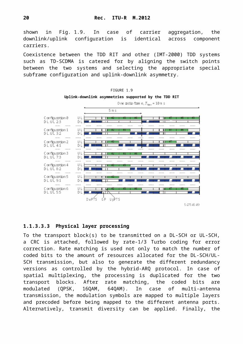
Different asymmetries in terms of the amount of resources allocated for uplink and downlink transmission, respectively, are provided through seven different downlink/uplink configurations as shown in Fig. 1.9. In case of carrier aggregation, the downlink/uplink configuration is identical across component carriers.
Coexistence between the TDD RIT and other (IMT-2000) TDD systems such as TD-SCDMA is catered for by aligning the switch points between the two systems and selecting the appropriate special subframe configuration and uplink-downlink asymmetry.
FIGURE 1.9Uplink-downlink asymmetries supported by the TDD RIT
Rec. ITU-R M.2012 15
1.1.3.3.3 Physical layer processing
To the transport block(s) to be transmitted on a DL-SCH or UL-SCH, a CRC is attached, followed by rate-1/3 Turbo coding for error correction. Rate matching is used not only to match the number of coded bits to the amount of resources allocated for the DL-SCH/UL-SCH transmission, but also to generate the different redundancy versions as controlled by the hybrid-ARQ protocol. In case of spatial multiplexing, the processing is duplicated for the two transport blocks. After rate matching, the coded bits are modulated (QPSK, 16QAM, 64QAM). In case of multi-antenna transmission, the modulation symbols are mapped to multiple layers and precoded before being mapped to the different antenna ports. Alternatively, transmit diversity can be applied. Finally, the (precoded) modulation symbols are mapped to the time-frequency resources allocated for the transmission.
Downlink transmission is based on conventional OFDM with a cyclic prefix. The subcarrier spacing is f = 15 kHz and two cyclic prefix lengths are supported: normal cyclic prefix 4.7 µs and extended cyclic prefix 16.7 µs. In the frequency domain, the number of resource blocks can range from 6 to 110 per component carrier (for channel bandwidths ranging from 1.4 to 20 MHz respectively), where a resource block is 180 kHz in the frequency domain. There can be up to five component carriers transmitted in parallel implying an overall bandwidth up to 100 MHz.
Uplink transmission is based on DFT-spread OFDM (DFTS-OFDM). DFTS-OFDM can be seen as a DFT precoder, followed by conventional OFDM with the same numerology as in the downlink. Multiple DFT precoding sizes, corresponding to transmission with different scheduled bandwidths, can be used.
The remaining downlink transport channels (PCH, BCH, MCH) are based on the same general physical-layer processing as DL-SCH, although with some restrictions in the set of features used.
1.1.3.3.4 Multi-antenna transmission
A wide range of multi-antenna transmission schemes are supported in the downlink:– Single-antenna transmission using a single cell-specific reference signal. – Closed-loop spatial multiplexing, also known as codebook-based beam-forming or
precoding, of up to four layers using cell-specific reference signals. Feedback reports from the terminal are used to assist the eNodeB in selecting a suitable precoding matrix.
– Open-loop spatial multiplexing, also known as large-delay cyclic delay diversity, of up to four layers using cell-specific reference signals.
– Spatial multiplexing of up to eight layers using UE-specific reference signals. The eNodeB may use feedback reports or exploit channel reciprocity to set the beam-forming weights.
– Transmit diversity based on space-frequency block coding (SFBC) or a combination of SFBC and Frequency Switched Transmit Diversity (FSTD).
– Multi-user MIMO where multiple terminals are assigned overlapping time-frequency resources.
The following multi-antenna transmission schemes are supported in the uplink:– Single-antenna transmission.– Precoding supporting rank-adaptive spatial multiplexing with one up to four layers.
1.1.3.3.5 Link adaptation and power control
According to the radio channel conditions, the Modulation and Coding Scheme (MCS) can be adapted flexibly. The same modulation and coding is applied to all resource units assigned to the same transport block within a TTI. Uplink power control determines the average power over a DFTS-OFDM symbol in which the physical channel is transmitted.
16 Rec. ITU-R M.2012
1.1.3.3.6 L1/L2 control signalling
Downlink control information (DCI) is transmitted in the first one to three OFDM symbols of each downlink subframe in each component carrier with the number of OFDM symbols being indicated on the PCFICH. Downlink and uplink scheduling grants (consisting of UE identity, time-frequency resources and transport format) and hybrid-ARQ acknowledgements are transmitted on the PDCCH and PHICH, respectively. Each grant is transmitted on a separate PDCCH using QPSK modulation.
Uplink control information (UCI), consisting of channel-status information, scheduling requests and hybrid-ARQ acknowledgements, is transmitted at the band edges of the primary uplink component carrier. Alternatively, parts of the control signalling can be multiplexed with data on PUSCH.
1.1.3.3.7 MBSFN operation
Multicast/Broadcast over Single Frequency Network (MBSFN) transmission, where the same signal is transmitted from multiple, time-synchronized cells, is supported by the MCH transport channel. One component carrier can support simultaneous unicast and broadcast support through time-domain multiplexing of MCH and DL-SCH transmissions.
1.2 Detailed specification of the radio interface technology
Detailed specifications described in this Annex are developed around a “Global Core Specification” (GCS)9, which is related to externally developed materials incorporated by specific references for a specific technology. The process and use of the GCS, references, and related notifications and certifications are found as Document IMT-ADV/24.
The IMT-Advanced standards contained in this section are derived from the global core specification for LTE-Advanced contained at http://ties.itu.int/u/ITU - r/ede/rsg5/IMT-Advanced/GCS/LTE-Advanced/ . The following notes apply to the sections below: 1) The identified Transposing Organizations10 should make their reference material available
from their website. 2) This information was supplied by the Transposing Organizations and relates to their own
deliverables of the transposed global core specification.
Section 1.2.1 contains titles and synopses of the Global Core Specification of IMT-Advanced radio interface technology entitled LTE-Advanced and the related hyperlinks to the transposed standards. Specifications listed in 1.2.2 are not part of the LTE-Advanced GCS.
The specific 3GPP specifications of the GCS for LTE-Advanced that are being transposed in section 1.2.1 are summarized in Table 1.1:
9 A “GCS” (Global Core Specification) is the set of specifications that defines a single RIT, an SRIT, or a RIT within an SRIT.
10 The following identified Transposing Organizations have provided their transposed sets of standards information contained in this section:
– Association of Radio Industries and Businesses (ARIB).
– Alliance for Telecommunications Industry Solutions (ATIS).
– China Communications Standards Association (CCSA).
– European Telecommunications Standards Institute (ETSI).
– Telecommunications Technology Association (TTA).
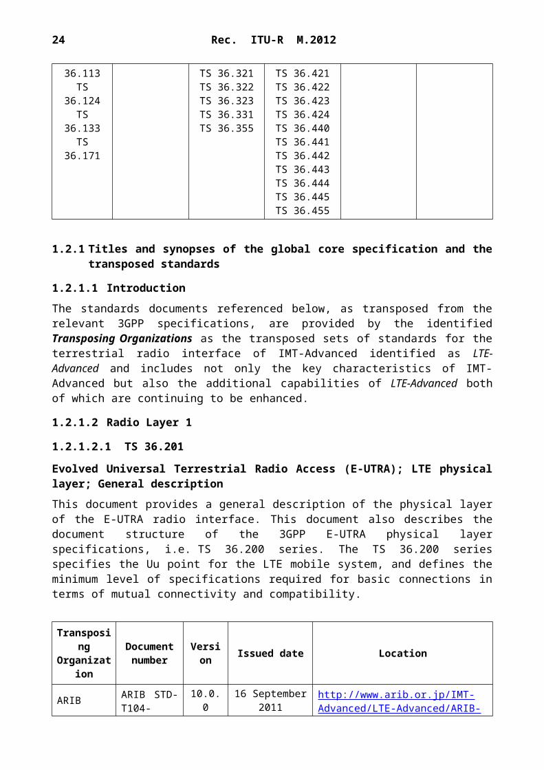
1.2.1 Titles and synopses of the global core specification and the transposed standards
1.2.1.1 Introduction
The standards documents referenced below, as transposed from the relevant 3GPP specifications, are provided by the identified Transposing Organizations as the transposed sets of standards for the terrestrial radio interface of IMT-Advanced identified as LTE-Advanced and includes not only the key characteristics of IMT-Advanced but also the additional capabilities of LTE-Advanced both of which are continuing to be enhanced.
1.2.1.2 Radio Layer 1
1.2.1.2.1 TS 36.201
Evolved Universal Terrestrial Radio Access (E-UTRA); LTE physical layer; General description
This document provides a general description of the physical layer of the E-UTRA radio interface. This document also describes the document structure of the 3GPP E-UTRA physical layer specifications, i.e. TS 36.200 series. The TS 36.200 series specifies the Uu point for the LTE mobile system, and defines the minimum level of specifications required for basic connections in terms of mutual connectivity and compatibility.
ETSI ETSI TS 136 213 10.2.0 28 June 2011 http://pda.etsi.org/pda/home.asp?
wkr=RTS/TSGR-0136213va20
TTATTAT.3G-36.213(R10-10.2.0)
10.2.0 26 August 2011http://www.tta.or.kr/data/ttasDown.jsp?where=14688&pk_num=TTAT.3G-36.213(R10-10.2.0)
TTC Not applicable Not applicable
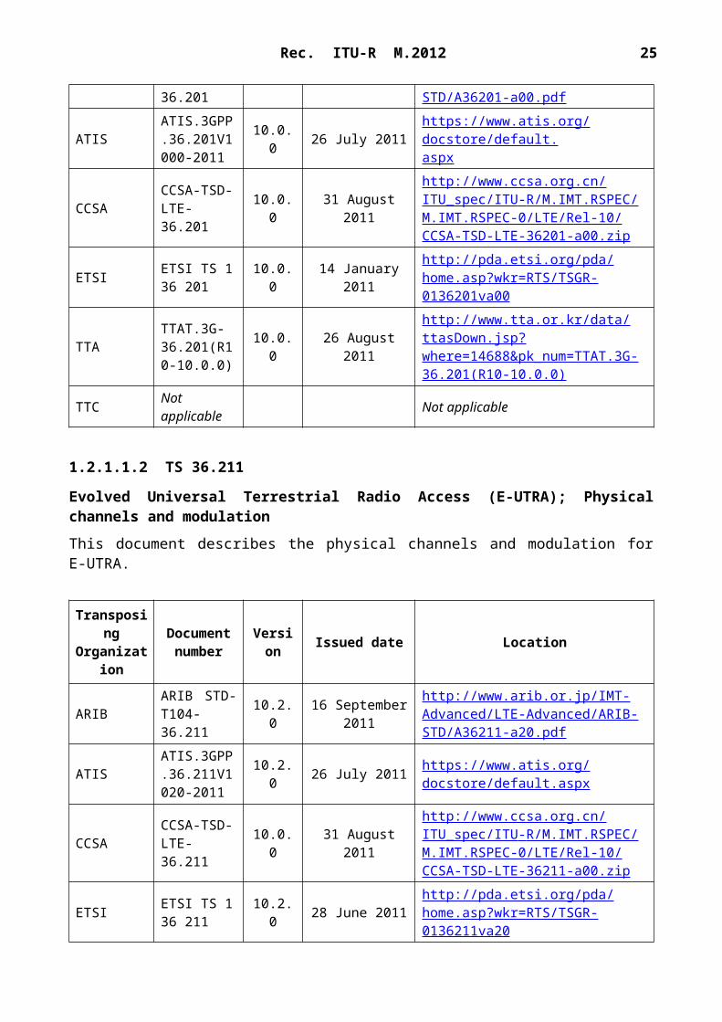
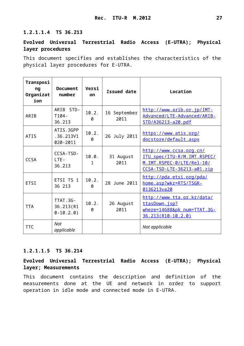
1.2.1.1.5 TS 36.214
Evolved Universal Terrestrial Radio Access (E-UTRA); Physical layer; Measurements
This document contains the description and definition of the measurements done at the UE and network in order to support operation in idle mode and connected mode in E-UTRA.
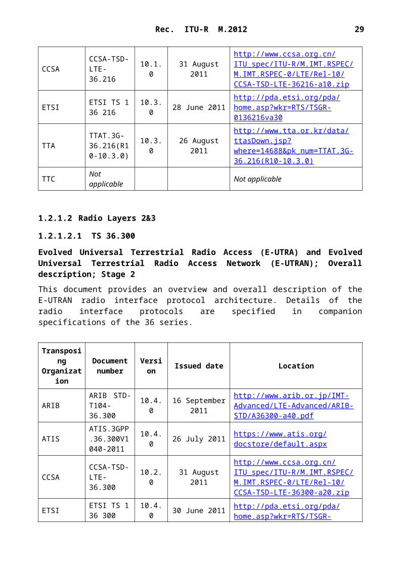
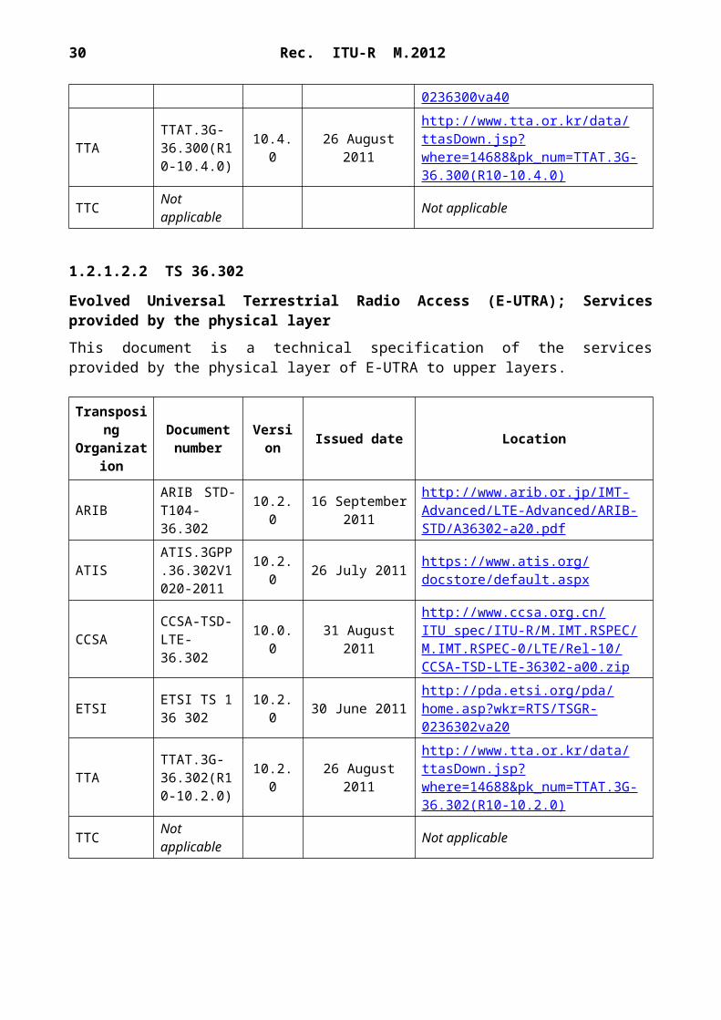
Evolved Universal Terrestrial Radio Access (E-UTRA) and Evolved Universal Terrestrial Radio Access Network (E-UTRAN); Overall description; Stage 2
This document provides an overview and overall description of the E-UTRAN radio interface protocol architecture. Details of the radio interface protocols are specified in companion specifications of the 36 series.
10.2.0 26 August 2011http://www.tta.or.kr/data/ttasDown.jsp?where=14688&pk_num=TTAT.3G-36.302(R10-10.2.0)
TTC Not applicable Not applicable
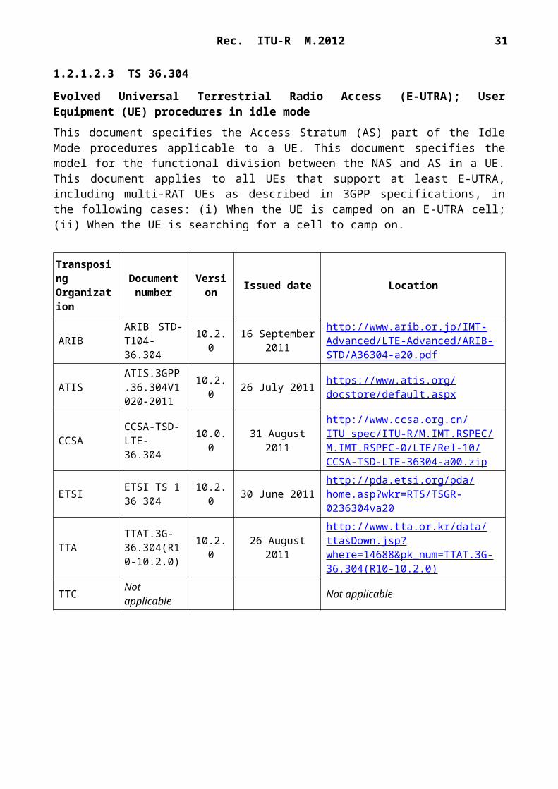
1.2.1.2.3 TS 36.304
Evolved Universal Terrestrial Radio Access (E-UTRA); User Equipment (UE) procedures in idle mode
This document specifies the Access Stratum (AS) part of the Idle Mode procedures applicable to a UE. This document specifies the model for the functional division between the NAS and AS in a UE. This document applies to all UEs that support at least E-UTRA, including multi-RAT UEs as described in 3GPP specifications, in the following cases: (i) When the UE is camped on an E-UTRA cell; (ii) When the UE is searching for a cell to camp on.
ETSI ETSI TS 136 304 10.2.0 30 June 2011 http://pda.etsi.org/pda/home.asp?
wkr=RTS/TSGR-0236304va20
TTATTAT.3G-36.304(R10-10.2.0)
10.2.0 26 August 2011http://www.tta.or.kr/data/ttasDown.jsp?where=14688&pk_num=TTAT.3G-36.304(R10-10.2.0)
TTC Not applicable Not applicable
1.2.1.2.4 TS 36.305
Evolved Universal Terrestrial Radio Access Network (E-UTRAN); Stage 2 functional specification of User Equipment (UE) positioning in E-UTRAN
This document specifies the stage 2 of the UE positioning function of E-UTRAN, which provides the mechanisms to support or assist the calculation of the geographical position of a UE. The purpose of this stage 2 specification is to define the E-UTRAN UE Positioning architecture, functional entities and operations to support positioning methods. This description is confined to the E-UTRAN Access Stratum. This stage 2 specification covers the E-UTRAN positioning methods, state descriptions, and message flows to support UE positioning.
Evolved Universal Terrestrial Radio Access (E-UTRA); Layer 2 – Measurements
This document contains the description and definition of the measurements performed by E-UTRAN that are transferred over the standardized interfaces in order to support E-UTRA radio link operations, radio resource management (RRM), network operations and maintenance (OAM), and self-organizing networks (SON).
ETSI ETSI TS 136 323 10.1.0 30 March 2011 http://pda.etsi.org/pda/home.asp?
wkr=RTS/TSGR-0236323va10
TTATTAT.3G-36.323(R10-10.1.0)
10.1.0 26 August 2011http://www.tta.or.kr/data/ttasDown.jsp?where=14688&pk_num=TTAT.3G-36.323(R10-10.1.0)
TTC Not applicable Not applicable
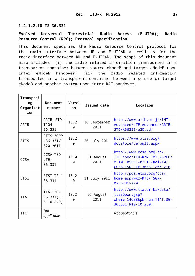
1.2.1.2.10 TS 36.331
Evolved Universal Terrestrial Radio Access (E-UTRA); Radio Resource Control (RRC); Protocol specification
This document specifies the Radio Resource Control protocol for the radio interface between UE and E-UTRAN as well as for the radio interface between RN and E-UTRAN. The scope of this document also includes: (i) the radio related information transported in a transparent container between source eNodeB and target eNodeB upon inter eNodeB handover; (ii) the radio related information transported in a transparent container between a source or target eNodeB and another system upon inter RAT handover.
Evolved Universal Terrestrial Radio Access Network (E-UTRAN); S1 layer 1 general aspects and principles
This document is an introduction to the 3GPP TS 36.41x series of technical specifications that define the S1 interface for the interconnection of the eNodeB component of the Evolved Universal Terrestrial Radio Access Network (E UTRAN) to the Core Network of the EPS system.
TransposingOrganization
Document number Version Issued date Location
ARIB Not applicable Not applicable
ATISATIS.3GPP.36.410V1010-2011
10.1.0 26 July 2011 https://www.atis.org/docstore/default.aspx
ETSI ETSI TS 136 410 10.1.0 30 June 2011 http://pda.etsi.org/pda/home.asp?
wkr=RTS/TSGR-0336410va10
TTATTAT.3G-36.410(R10-10.1.0)
10.1.0 26 August 2011http://www.tta.or.kr/data/ttasDown.jsp?where=14688&pk_num=TTAT.3G-36.410(R10-10.1.0)
TTCTS-3GA-36.410(Rel10)v10.1.0
10.1.0 31 August 2011 http://www.ttc.or.jp/imt/ts/ts36410rel10va10.pdf
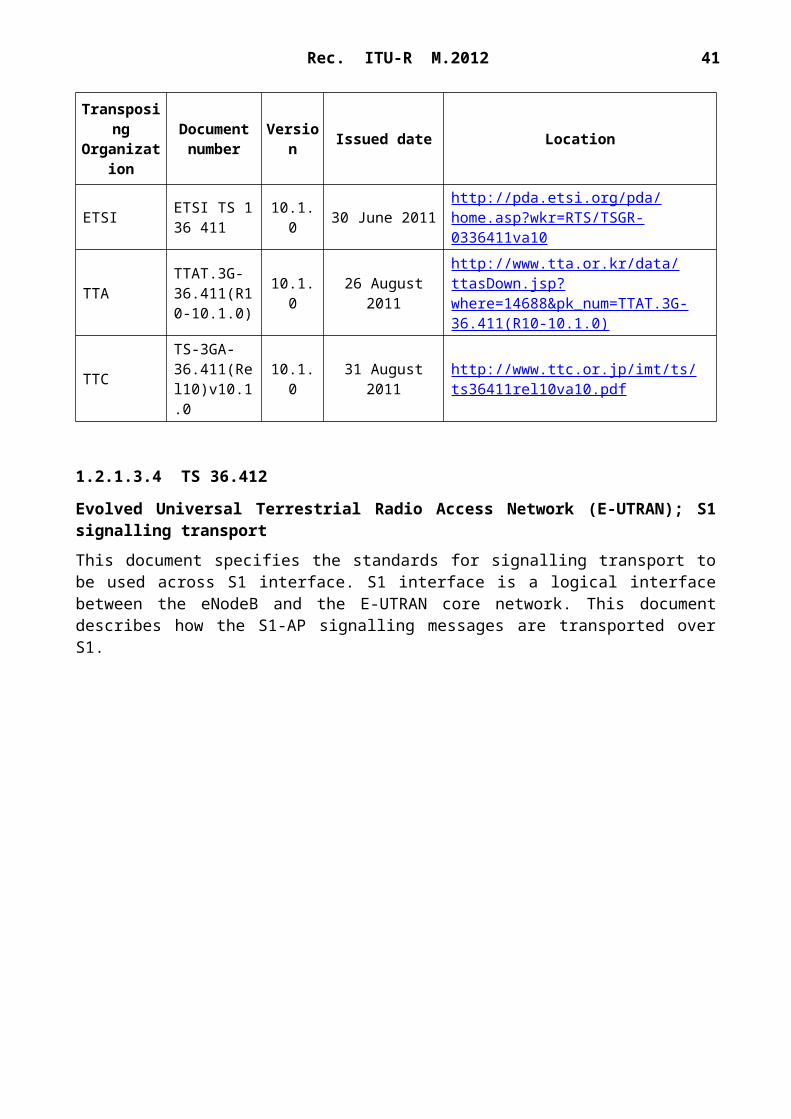
1.2.1.3.3 TS 36.411
Evolved Universal Terrestrial Radio Access Network (E-UTRAN); S1 layer 1
This document specifies the standards allowed to implement layer 1 on the S1 interface. The specification of transmission delay requirements and O&M requirements are not in the scope of this document. In the following, “layer 1” and “physical layer” are assumed to be synonymous.
TransposingOrganization
Document number Version Issued date Location
ARIB Not applicable Not applicable
ATISATIS.3GPP.36.411V1010-2011
10.1.0 26 July 2011 https://www.atis.org/docstore/default.aspx
10.1.0 31 August 2011 http://www.ttc.or.jp/imt/ts/ts36411rel10va10.pdf
1.2.1.3.4 TS 36.412
Evolved Universal Terrestrial Radio Access Network (E-UTRAN); S1 signalling transport
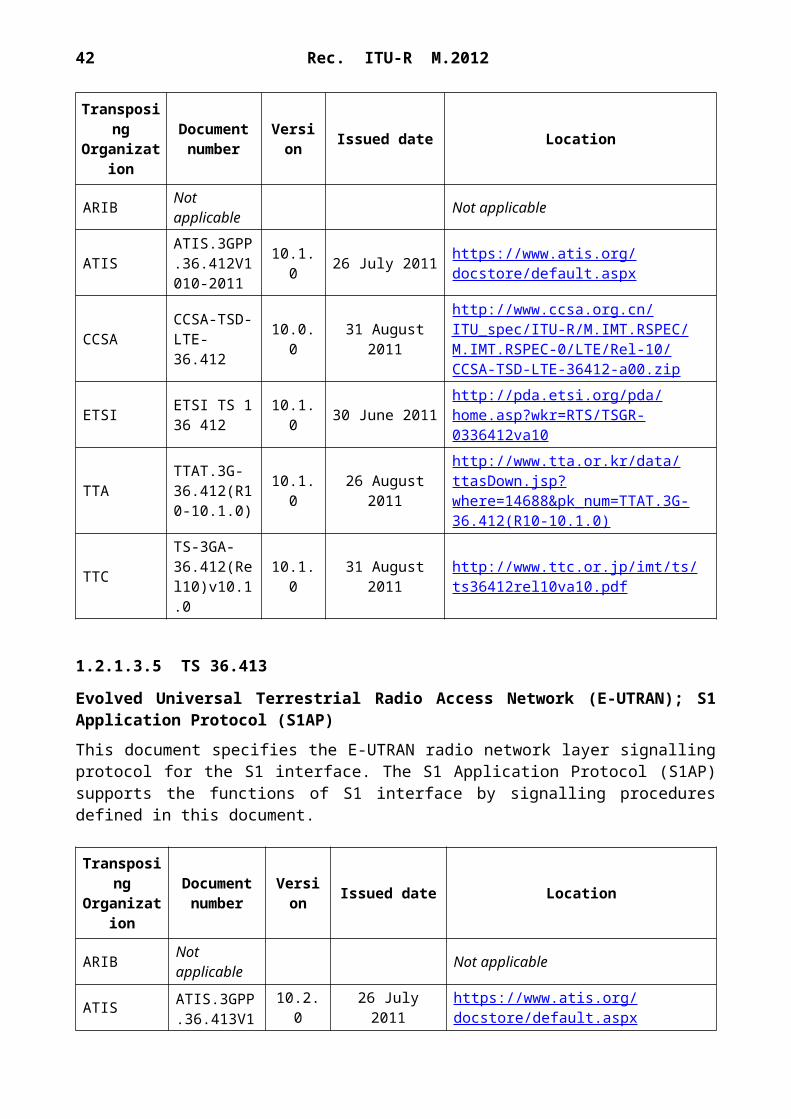
This document specifies the standards for signalling transport to be used across S1 interface. S1 interface is a logical interface between the eNodeB and the E-UTRAN core network. This document describes how the S1-AP signalling messages are transported over S1.
TransposingOrganization
Document number Version Issued date Location
ARIB Not applicable Not applicable
ATISATIS.3GPP.36.412V1010-2011
10.1.0 26 July 2011 https://www.atis.org/docstore/default.aspx
This document specifies the E-UTRAN radio network layer signalling protocol for the S1 interface. The S1 Application Protocol (S1AP) supports the functions of S1 interface by signalling procedures defined in this document.
ETSI ETSI TS 136 413 10.2.0 30 June 2011 http://pda.etsi.org/pda/home.asp?
wkr=RTS/TSGR-0336413va20
TTATTAT.3G-36.413(R10-10.2.0)
10.2.0 26 August 2011http://www.tta.or.kr/data/ttasDown.jsp?where=14688&pk_num=TTAT.3G-36.413(R10-10.2.0)
TTCTS-3GA-36.413(Rel10)v10.2.0
10.2.0 31 August 2011 http://www.ttc.or.jp/imt/ts/ts36413rel10va20.pdf
1.2.1.3.6 TS 36.414
Evolved Universal Terrestrial Radio Access Network (E-UTRAN); S1 data transport
This document specifies the standards for user data transport protocols and related signalling protocols to establish user plane transport bearers over the S1 interface.
TransposingOrganization
Document number Version Issued date Location
ARIB Not applicable Not applicable
ATISATIS.3GPP.36.414V1010-2011
10.1.0 26 July 2011 https://www.atis.org/docstore/default.aspx
ETSI ETSI TS 136 414 10.1.0 30 June 2011 http://pda.etsi.org/pda/home.asp?
wkr=RTS/TSGR-0336414va10
TTATTAT.3G-36.414(R10-10.1.0)
10.1.0 26 August 2011http://www.tta.or.kr/data/ttasDown.jsp?where=14688&pk_num=TTAT.3G-36.414(R10-10.1.0)
TTCTS-3GA-36.414(Rel10)v10.1.0
10.1.0 31 August 2011 http://www.ttc.or.jp/imt/ts/ts36414rel10va10.pdf
1.2.1.3.7 TS 36.420
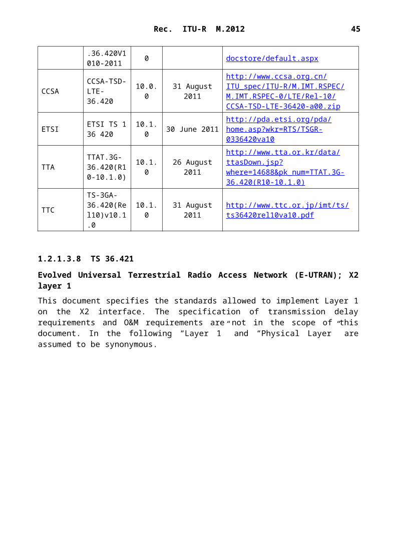
Evolved Universal Terrestrial Radio Access Network (E-UTRAN); X2 general aspects and principles
This document is an introduction to the TSG RAN TS 36.42x series of UMTS technical specifications that define the X2 interface. It is an interface for the interconnection of two E-UTRAN NodeB (eNodeB) components within the Evolved Universal Terrestrial Radio Access Network (E-UTRAN) architecture.
ETSI ETSI TS 136 420 10.1.0 30 June 2011 http://pda.etsi.org/pda/home.asp?
wkr=RTS/TSGR-0336420va10
TTATTAT.3G-36.420(R10-10.1.0)
10.1.0 26 August 2011http://www.tta.or.kr/data/ttasDown.jsp?where=14688&pk_num=TTAT.3G-36.420(R10-10.1.0)
TTCTS-3GA-36.420(Rel10)v10.1.0
10.1.0 31 August 2011 http://www.ttc.or.jp/imt/ts/ts36420rel10va10.pdf
1.2.1.3.8 TS 36.421
Evolved Universal Terrestrial Radio Access Network (E-UTRAN); X2 layer 1
This document specifies the standards allowed to implement Layer 1 on the X2 interface. The specification of transmission delay requirements and O&M requirements are not in the scope of this document. In the following “Layer 1” and “Physical Layer” are assumed to be synonymous.
TransposingOrganization
Document number Version Issued date Location
ARIB Not applicable Not applicable
ATISATIS.3GPP.36.421V1001-2011
10.0.1 26 July 2011 https://www.atis.org/docstore/default.aspx
Evolved Universal Terrestrial Radio Access Network (E-UTRAN); X2 signalling transport
This document specifies the standards for Signalling Transport to be used across X2 interface. X2 interface is a logical interface between eNodeBs. This document describes how the X2-AP signalling messages are transported over X2.
TransposingOrganization
Document number Version Issued date Location
ARIB Not applicable Not applicable
ATISATIS.3GPP.36.422V1010-2011
10.1.0 26 July 2011 https://www.atis.org/docstore/default.aspx
This document specifies the radio network layer signalling procedures of the control plane between eNodeBs in E-UTRAN. X2AP supports the functions of X2 interface by signalling procedures defined in this document.
TransposingOrganization
Document number Version Issued date Location
ARIB Not applicable Not applicable
ATISATIS.3GPP.36.423V1020-2011
10.2.0 26 July 2011 https://www.atis.org/docstore/default.aspx
10.2.0 31 August 2011 http://www.ttc.or.jp/imt/ts/ts36423rel10va20.pdf
1.2.1.3.11 TS 36.424
Evolved Universal Terrestrial Radio Access Network (E-UTRAN); X2 data transport
This document specifies the standards for user data transport protocols and related signalling protocols to establish user plane transport bearers over the X2 interface.
TransposingOrganization
Document number Version Issued date Location
ARIB Not applicable Not applicable
ATISATIS.3GPP.36.424V1010-2011
10.1.0 26 July 2011 https://www.atis.org/docstore/default.aspx
ETSI ETSI TS 136 424 10.1.0 30 June 2011 http://pda.etsi.org/pda/home.asp?
wkr=RTS/TSGR-0336424va10
TTATTAT.3G-36.424(R10-10.1.0)
10.1.0 26 August 2011http://www.tta.or.kr/data/ttasDown.jsp?where=14688&pk_num=TTAT.3G-36.424(R10-10.1.0)
TTCTS-3GA-36.424(Rel10)v10.1.0
10.1.0 31 August 2011 http://www.ttc.or.jp/imt/ts/ts36424rel10va10.pdf
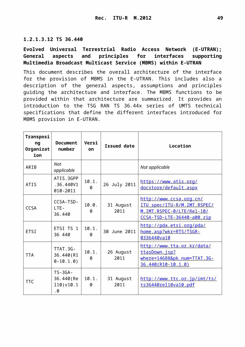
1.2.1.3.12 TS 36.440
Evolved Universal Terrestrial Radio Access Network (E-UTRAN); General aspects and principles for interfaces supporting Multimedia Broadcast Multicast Service (MBMS) within E-UTRAN
This document describes the overall architecture of the interface for the provision of MBMS in the E-UTRAN. This includes also a description of the general aspects, assumptions and principles guiding the architecture and interface. The MBMS functions to be provided within that architecture are summarized. It provides an introduction to the TSG RAN TS 36.44x series of UMTS technical specifications that define the different interfaces introduced for MBMS provision in E-UTRAN.
TransposingOrganization
Document number Version Issued date Location
ARIB Not applicable Not applicable
ATIS ATIS.3GPP.36.440V1010
10.1.0 26 July 2011 https://www.atis.org/docstore/default.aspx
ETSI ETSI TS 136 440 10.1.0 30 June 2011 http://pda.etsi.org/pda/home.asp?
wkr=RTS/TSGR-0336440va10
TTATTAT.3G-36.440(R10-10.1.0)
10.1.0 26 August 2011http://www.tta.or.kr/data/ttasDown.jsp?where=14688&pk_num=TTAT.3G-36.440(R10-10.1.0)
TTCTS-3GA-36.440(Rel10)v10.1.0
10.1.0 31 August 2011 http://www.ttc.or.jp/imt/ts/ts36440rel10va10.pdf
1.2.1.3.13 TS 36.441
Evolved Universal Terrestrial Radio Access Network (E-UTRAN); Layer 1 for interfaces supporting Multimedia Broadcast Multicast Service (MBMS) within E-UTRAN
This document specifies the standards allowed to implement layer 1 on the interfaces supporting Multimedia Broadcast Multicast Service (MBMS) within E-UTRAN. In the following, “layer 1” and “physical layer” are assumed to be synonymous.
TransposingOrganization
Document number Version Issued date Location
ARIB Not applicable Not applicable
ATISATIS.3GPP.36.441V1010-2011
10.1.0 26 July 2011 https://www.atis.org/docstore/default.aspx
ETSI ETSI TS 136 441 10.1.0 30 June 2011 http://pda.etsi.org/pda/home.asp?
wkr=RTS/TSGR-0336441va10
TTATTAT.3G-36.441(R10-10.1.0)
10.1.0 26 August 2011http://www.tta.or.kr/data/ttasDown.jsp?where=14688&pk_num=TTAT.3G-36.441(R10-10.1.0)
TTCTS-3GA-36.441(Rel10)v10.1.0
10.1.0 31 August 2011 http://www.ttc.or.jp/imt/ts/ts36441rel10va10.pdf
1.2.1.3.14 TS 36.442
Evolved Universal Terrestrial Radio Access Network (E-UTRAN); Signalling Transport for interfaces supporting Multimedia Broadcast Multicast Service (MBMS) within E-UTRAN
This document specifies the standards for signalling transport to be used across M2 and M3 interfaces. M2 interface is a logical interface between the eNodeB and the MCE. M3 interface is a logical interface between the MCE and the MME. This document describes how the M2-AP
This document specifies the E-UTRAN radio network layer signalling protocol for the M2 interface. The M2 Application Protocol (M2AP) supports the functions of M2 interface by signalling procedures defined in this document.
TransposingOrganization
Document number Version Issued date Location
ARIB Not applicable Not applicable
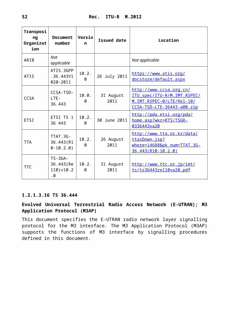
ATISATIS.3GPP.36.443V1020-2011
10.2.0 26 July 2011 https://www.atis.org/docstore/default.aspx
This document specifies the E-UTRAN radio network layer signalling protocol for the M3 interface. The M3 Application Protocol (M3AP) supports the functions of M3 interface by signalling procedures defined in this document.
TransposingOrganization
Document number Version Issued date Location
ARIB Not applicable Not applicable
ATISATIS.3GPP.36.444V1020-2011
10.2.0 26 July 2011 https://www.atis.org/docstore/default.aspx
10.1.0 26 August 2011http://www.tta.or.kr/data/ttasDown.jsp?where=14688&pk_num=TTAT.3G-36.445(R10-10.1.0)
TTCTS-3GA-36.445(Rel10)v10.1.0
10.1.0 31 August 2011 http://www.ttc.or.jp/imt/ts/ts36445rel10va10.pdf
1.2.1.3.18 TS 36.455
Evolved Universal Terrestrial Radio Access (E-UTRA); LTE Positioning Protocol A (LPPa)
This document specifies the control plane radio network layer signalling procedures between eNodeB and E-SMLC. LPPa supports the concerned functions by signalling procedures defined in this document.
TransposingOrganization
Document number Version Issued date Location
ARIB Not applicable Not applicable
ATISATIS.3GPP.36.455V1010-2011
10.1.0 26 July 2011 https://www.atis.org/docstore/default.aspx
ETSI ETSI TS 136 455 10.1.0 30 June 2011 http://pda.etsi.org/pda/home.asp?
wkr=RTS/TSGR-0336455va10
TTATTAT.3G-36.455(R10-10.1.0)
10.1.0 26 August 2011http://www.tta.or.kr/data/ttasDown.jsp?where=14688&pk_num=TTAT.3G-36.455(R10-10.1.0)
TTCTS-3GA-36.455(Rel10)v10.1.0
10.1.0 31 August 2011 http://www.ttc.or.jp/imt/ts/ts36455rel10va10.pdf
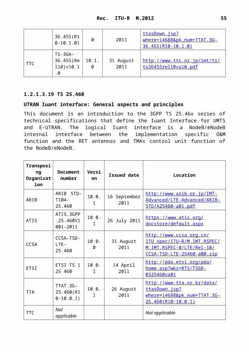
1.2.1.3.19 TS 25.460
UTRAN Iuant interface: General aspects and principles
This document is an introduction to the 3GPP TS 25.46x series of technical specifications that define the Iuant Interface for UMTS and E-UTRAN. The logical Iuant interface is a NodeB/eNodeB internal interface between the implementation specific O&M function and the RET antennas and TMAs control unit function of the NodeB/eNodeB.
ETSI ETSI TS 125 460 10.0.1 14 April 2011 http://pda.etsi.org/pda/home.asp?
wkr=RTS/TSGR-0325460va01
TTATTAT.3G-25.460(R10-10.0.1)
10.0.1 26 August 2011http://www.tta.or.kr/data/ttasDown.jsp?where=14688&pk_num=TTAT.3G-25.460(R10-10.0.1)
TTC Not applicable Not applicable
1.2.1.3.20 TS 25.461
UTRAN Iuant interface: Layer 1
This document specifies the standards allowed to implement layer 1 on the Iuant interface. The specification of transmission delay requirements and O&M requirements are not in the scope of this document.
ETSI ETSI TS 125 461 10.2.0 30 June 2011 http://pda.etsi.org/pda/home.asp?
wkr=RTS/TSGR-0325461va20
TTATTAT.3G-25.461(R10-10.2.0)
10.2.0 26 August 2011http://www.tta.or.kr/data/ttasDown.jsp?where=14688&pk_num=TTAT.3G-25.461(R10-10.2.0)
TTC Not applicable Not applicable
1.2.1.3.21 TS 25.462
UTRAN Iuant interface: Signalling transport
This document specifies the signalling transport related to RETAP and TMAAP signalling to be used across the Iuant interface. The logical Iuant interface is a NodeB/eNodeB internal interface
ETSI ETSI TS 125 462 10.1.0 30 June 2011 http://pda.etsi.org/pda/home.asp?
wkr=RTS/TSGR-0325462va10
TTATTAT.3G-25.462(R10-10.1.0)
10.1.0 26 August 2011http://www.tta.or.kr/data/ttasDown.jsp?where=14688&pk_num=TTAT.3G-25.462(R10-10.1.0)
TTC Not applicable Not applicable
1.2.1.3.22 TS 25.466
UTRAN Iuant interface: Application part
This document specifies the Remote Electrical Tilting Application Part (RETAP) between the implementation specific O&M transport function and the RET Antenna Control unit function of the NodeB/eNodeB. The document also specifies the Tower Mounted Amplifier Application Part (TMAAP) between the implementation specific O&M transport function and the TMA control function of the NodeB/eNodeB. It defines the Iuant interface and its associated signalling procedures.
ETSI ETSI TS 136 106 10.1.0 24 May 2011 http://pda.etsi.org/pda/home.asp?
wkr=RTS/TSGR-0436106va10
TTATTAT.3G-36.106(R10-10.1.0)
10.1.0 26 August 2011http://www.tta.or.kr/data/ttasDown.jsp?where=14688&pk_num=TTAT.3G-36.106(R10-10.1.0)
TTC Not applicable Not applicable
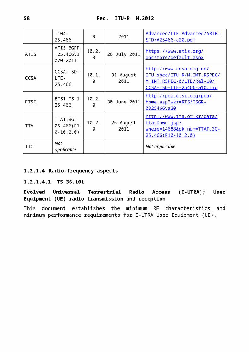
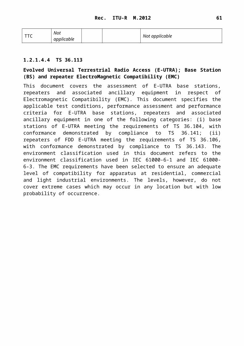
1.2.1.4.4 TS 36.113
Evolved Universal Terrestrial Radio Access (E-UTRA); Base Station (BS) and repeater ElectroMagnetic Compatibility (EMC)
This document covers the assessment of E-UTRA base stations, repeaters and associated ancillary equipment in respect of Electromagnetic Compatibility (EMC). This document specifies the applicable test conditions, performance assessment and performance criteria for E-UTRA base
stations, repeaters and associated ancillary equipment in one of the following categories: (i) base stations of E-UTRA meeting the requirements of TS 36.104, with conformance demonstrated by compliance to TS 36.141; (ii) repeaters of FDD E-UTRA meeting the requirements of TS 36.106, with conformance demonstrated by compliance to TS 36.143. The environment classification used in this document refers to the environment classification used in IEC 61000-6-1 and IEC 61000-6-3. The EMC requirements have been selected to ensure an adequate level of compatibility for apparatus at residential, commercial and light industrial environments. The levels, however, do not cover extreme cases which may occur in any location but with low probability of occurrence.
ETSI ETSI TS 136 113 10.3.0 23 June 2011 http://pda.etsi.org/pda/home.asp?
wkr=RTS/TSGR-0436113va30
TTATTAT.3G-36.113(R10-10.3.0)
10.3.0 26 August 2011http://www.tta.or.kr/data/ttasDown.jsp?where=14688&pk_num=TTAT.3G-36.113(R10-10.3.0)
TTC Not applicable Not applicable
1.2.1.4.5 TS 36.124
Evolved Universal Terrestrial Radio Access (E-UTRA); Electromagnetic compatibility (EMC) requirements for mobile terminals and ancillary equipment
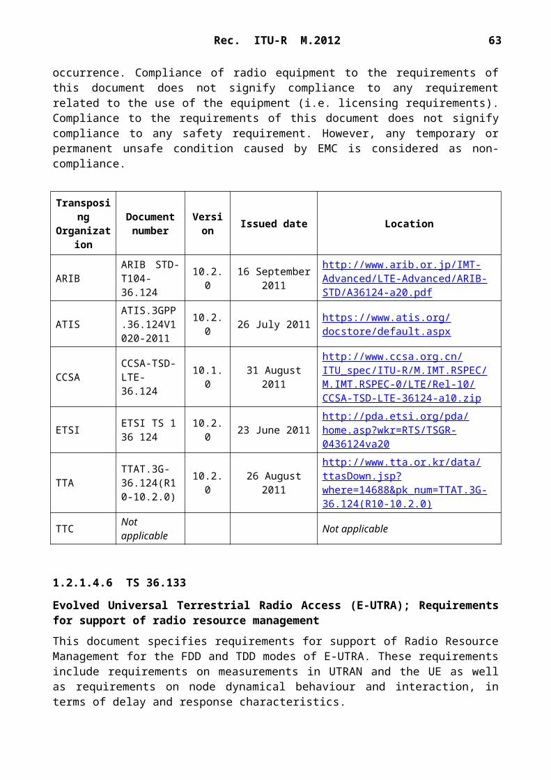
This document establishes the essential EMC requirements for “3rd generation” digital cellular mobile terminal equipment and ancillary accessories in combination with a 3GPP E-UTRA user equipment (UE). This document specifies the applicable EMC tests, the methods of measurement, the frequency range, the limits and the minimum performance criteria for all types of E-UTRA UEs and their accessories. Requirements for the radiated emission from the enclosure port of integral antenna equipment and ancillaries have been included. The immunity requirements have been selected to ensure an adequate level of compatibility for apparatus in residential, commercial, light industrial and vehicular environments. The levels however, do not cover extreme cases, which may occur in any location but with low probability of occurrence. Compliance of radio equipment to the requirements of this document does not signify compliance to any requirement related to the use of the equipment (i.e. licensing requirements). Compliance to the requirements of this document does not signify compliance to any safety requirement. However, any temporary or permanent unsafe condition caused by EMC is considered as non-compliance.
ETSI ETSI TS 136 124 10.2.0 23 June 2011 http://pda.etsi.org/pda/home.asp?
wkr=RTS/TSGR-0436124va20
TTATTAT.3G-36.124(R10-10.2.0)
10.2.0 26 August 2011http://www.tta.or.kr/data/ttasDown.jsp?where=14688&pk_num=TTAT.3G-36.124(R10-10.2.0)
TTC Not applicable Not applicable
1.2.1.4.6 TS 36.133
Evolved Universal Terrestrial Radio Access (E-UTRA); Requirements for support of radio resource management
This document specifies requirements for support of Radio Resource Management for the FDD and TDD modes of E-UTRA. These requirements include requirements on measurements in UTRAN and the UE as well as requirements on node dynamical behaviour and interaction, in terms of delay and response characteristics.
ETSI ETSI TS 136 171 10.1.0 27 May 2011 http://pda.etsi.org/pda/home.asp?
wkr=RTS/TSGR-0436171va10
TTATTAT.3G-36.171(R10-10.1.0)
10.1.0 26 August 2011http://www.tta.or.kr/data/ttasDown.jsp?where=14688&pk_num=TTAT.3G-36.171(R10-10.1.0)
TTC Not applicable Not applicable
1.2.1.4.8 TS 36.307
Evolved Universal Terrestrial Radio Access (E-UTRA); Requirements on User Equipments (UEs) supporting a release-independent frequency band
This document specifies requirements on UEs supporting a frequency band that is independent of release. TSG-RAN has agreed that the standardization of new frequency bands may be independent of a release. However, in order to implement a UE that conforms to a particular release but supports a band of operation that is specified in a later release, it is necessary to specify some extra requirements. All frequency bands are fully specified in this release of the specifications. This document does not contain any requirements for UEs supporting frequency bands independent of release.
ETSI ETSI TS 136 307 10.1.0 23 June 2011 http://pda.etsi.org/pda/home.asp?
wkr=RTS/TSGR-0436307va10
TTATTAT.3G-36.307(R10-10.1.0)
10.1.0 26 August 2011http://www.tta.or.kr/data/ttasDown.jsp?where=14688&pk_num=TTAT.3G-36.307(R10-10.1.0)
TTC Not applicable Not applicable
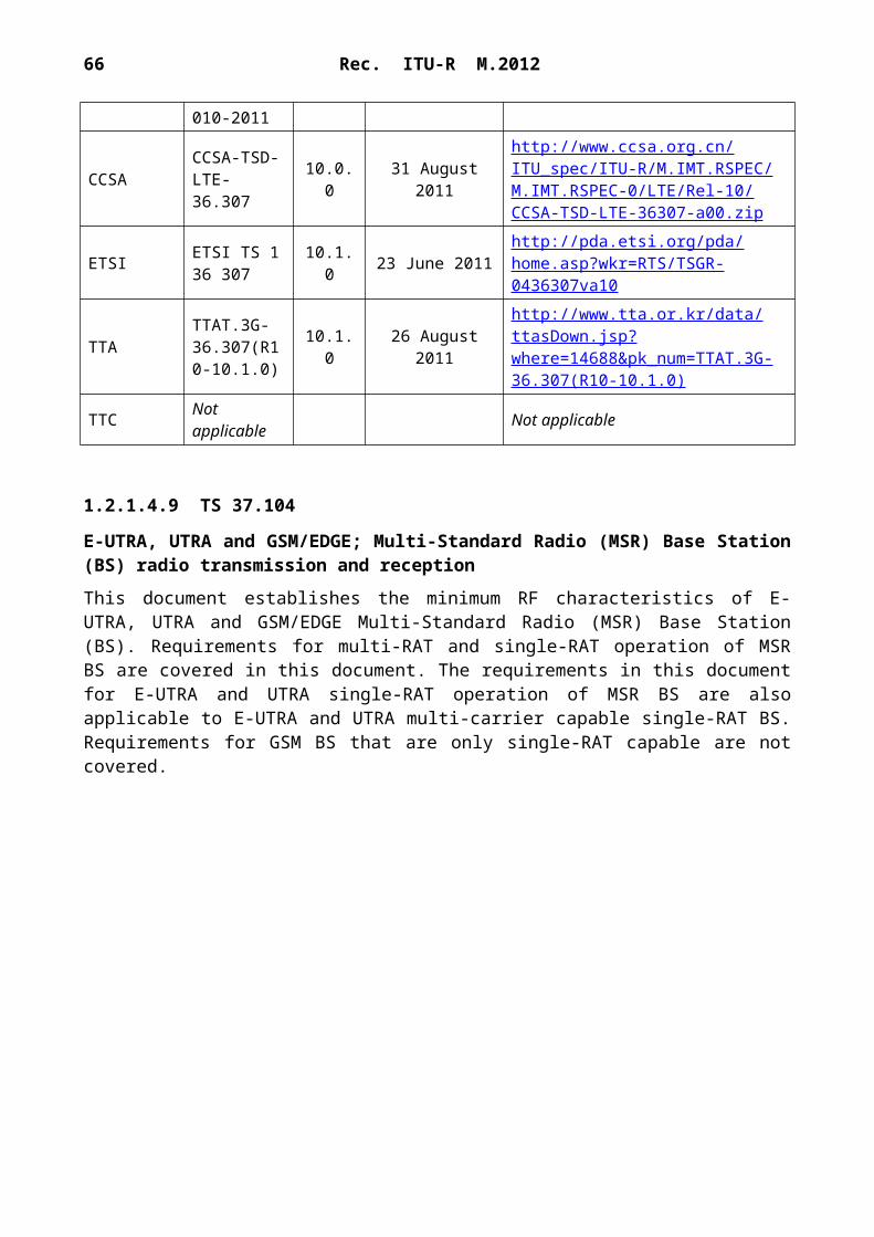
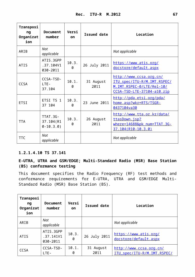
1.2.1.4.9 TS 37.104
E-UTRA, UTRA and GSM/EDGE; Multi-Standard Radio (MSR) Base Station (BS) radio transmission and reception
This document establishes the minimum RF characteristics of E-UTRA, UTRA and GSM/EDGE Multi-Standard Radio (MSR) Base Station (BS). Requirements for multi-RAT and single-RAT operation of MSR BS are covered in this document. The requirements in this document for E-UTRA and UTRA single-RAT operation of MSR BS are also applicable to E-UTRA and UTRA multi-carrier capable single-RAT BS. Requirements for GSM BS that are only single-RAT capable are not covered.
TransposingOrganizatio
n
Document number Version Issued date Location
ARIB Not applicable Not applicable
ATISATIS.3GPP.37.104V1030-2011
10.3.0 26 July 2011 https://www.atis.org/docstore/default.aspx
E-UTRA, UTRA and GSM/EDGE; Multi-Standard Radio (MSR) Base Station (BS) conformance testing
This document specifies the Radio Frequency (RF) test methods and conformance requirements for E-UTRA, UTRA and GSM/EDGE Multi-Standard Radio (MSR) Base Station (BS).
TransposingOrganizatio
n
Document number Version Issued date Location
ARIB Not applicable Not applicable
ATISATIS.3GPP.37.141V1030-2011
10.3.0 26 July 2011 https://www.atis.org/docstore/default.aspx
ETSI ETSI TS 137 141 10.3.0 23 June 2011 http://pda.etsi.org/pda/home.asp?
wkr=RTS/TSGR-0437141va30
TTATTAT.3G-37.141(R10-10.3.0)
10.3.0 26 August 2011http://www.tta.or.kr/data/ttasDown.jsp?where=14688&pk_num=TTAT.3G-37.141(R10-10.3.0)
TTC Not applicable Not applicable
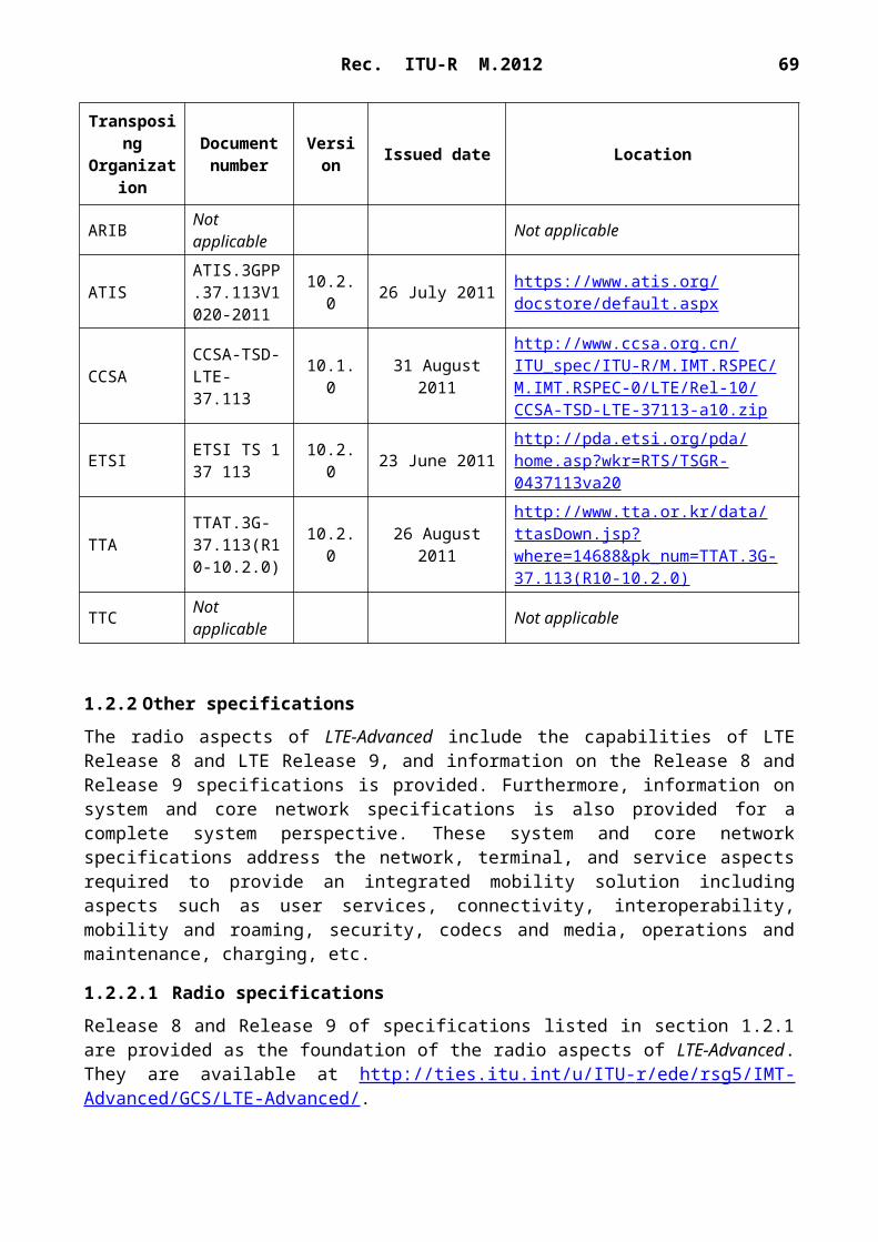
1.2.1.4.11 TS 37.113
E-UTRA, UTRA and GSM/EDGE; Multi-Standard Radio (MSR) Base Station (BS) Electromagnetic Compatibility (EMC)
This document covers the assessment of E-UTRA, UTRA and GSM/EDGE Multi-Standard Radio (MSR) Base Stations and associated ancillary equipment in respect of Electromagnetic Compatibility (EMC). This document specifies the applicable test conditions, performance assessment and performance criteria for E-UTRA, UTRA and GSM/EDGE Base Stations and associated ancillary equipment in one of the following categories: (i) Multi-Standard Radio (MSR) Base Stations for E-UTRA, UTRA and GSM/EDGE meeting the requirements of TS 37.104, with conformance demonstrated by compliance to TS 37.141; (ii) Base Stations for E-UTRA meeting the requirements of TS 36.104, with conformance demonstrated by compliance to TS 36.141; (iii) Base Stations for UTRA FDD meeting the requirements of TS 25.104, with conformance demonstrated by compliance to TS 25.141; (iv) Base Stations for UTRA TDD meeting the requirements of TS 25.105, with conformance demonstrated by compliance to TS 25.142; (v) Base Stations for GSM/EDGE meeting the requirements of TS 45.005, with conformance demonstrated by compliance to TS 51.021. The environment classification used in this document refers to the environment classification used in IEC 61000-6-1 and IEC 61000-6-3. The EMC requirements have been selected to ensure an adequate level of compatibility for apparatus at residential, commercial and light industrial environments. The levels, however, do not cover extreme cases which may occur in any location but with low probability of occurrence.
ETSI ETSI TS 137 113 10.2.0 23 June 2011 http://pda.etsi.org/pda/home.asp?
wkr=RTS/TSGR-0437113va20
TTATTAT.3G-37.113(R10-10.2.0)
10.2.0 26 August 2011http://www.tta.or.kr/data/ttasDown.jsp?where=14688&pk_num=TTAT.3G-37.113(R10-10.2.0)
TTC Not applicable Not applicable
1.2.2 Other specifications
The radio aspects of LTE-Advanced include the capabilities of LTE Release 8 and LTE Release 9, and information on the Release 8 and Release 9 specifications is provided. Furthermore, information on system and core network specifications is also provided for a complete system perspective. These system and core network specifications address the network, terminal, and service aspects required to provide an integrated mobility solution including aspects such as user services, connectivity, interoperability, mobility and roaming, security, codecs and media, operations and maintenance, charging, etc.
1.2.2.1 Radio specifications
Release 8 and Release 9 of specifications listed in section 1.2.1 are provided as the foundation of the radio aspects of LTE-Advanced. They are available at http://ties.itu.int/u/ITU - r/ede/rsg5/IMT- Advanced/GCS/LTE-Advanced/.
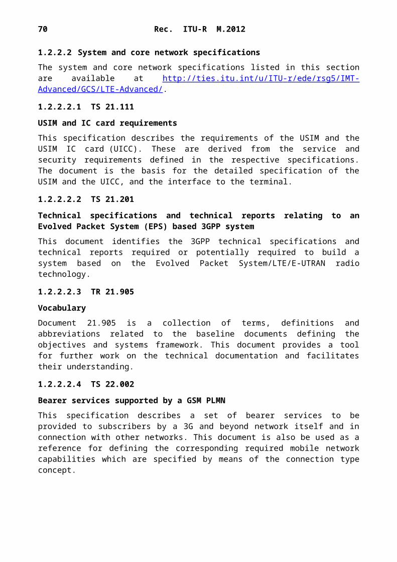
1.2.2.2 System and core network specifications
The system and core network specifications listed in this section are available at http://ties.itu.int/u/ITU - r/ede/rsg5/IMT-Advanced/GCS/LTE-Advanced/ .
1.2.2.2.1 TS 21.111
USIM and IC card requirements
This specification describes the requirements of the USIM and the USIM IC card (UICC). These are derived from the service and security requirements defined in the respective specifications. The document is the basis for the detailed specification of the USIM and the UICC, and the interface to the terminal.
Technical specifications and technical reports relating to an Evolved Packet System (EPS) based 3GPP system
This document identifies the 3GPP technical specifications and technical reports required or potentially required to build a system based on the Evolved Packet System/LTE/E-UTRAN radio technology.
1.2.2.2.3 TR 21.905
Vocabulary
Document 21.905 is a collection of terms, definitions and abbreviations related to the baseline documents defining the objectives and systems framework. This document provides a tool for further work on the technical documentation and facilitates their understanding.
1.2.2.2.4 TS 22.002
Bearer services supported by a GSM PLMN
This specification describes a set of bearer services to be provided to subscribers by a 3G and beyond network itself and in connection with other networks. This document is also be used as a reference for defining the corresponding required mobile network capabilities which are specified by means of the connection type concept.
1.2.2.2.5 TS 22.004
General on supplementary services
This specification describes a recommended set of supplementary services to the teleservices and bearer services which will be supported by a 3G and beyond network in connection with other networks as a basis for the definition of the network capabilities required.
1.2.2.2.6 TS 22.011
Service accessibility
This specification describes the service access procedures as presented to the user. The document contains definitions and procedures are provided for international roaming, national roaming and regionally provided service. These are mandatory in relation to the technical realization of the UE.
1.2.2.2.7 TS 22.016
International mobile equipment identities (IMEI)
This specification describes the principal purpose and use of unique equipment identities.
1.2.2.2.8 TS 22.022
Personalization of GSM ME mobile functionality specification – Stage 1
This specification describes functional specifications of five features to personalize UE. These features are called:– network personalization;– network subset personalization;– service provider (SP) personalization;– corporate personalization;
This specification describes requirements for UE, which provide these personalization features.
1.2.2.2.9 TS 22.034
High-speed circuit switched data (HSCSD) – Stage 1
This specification describes the Stage 1 description of HSCSD. HSCSD is a feature that allows users subscribing to the general bearer services to access user rates that can be achieved with one or more traffic channel. HSCSD also defines a flexible use of air interface resources, which makes efficient and flexible use of higher user rates feasible.
1.2.2.2.10 TS 22.038
SIM application toolkit (SAT) – Stage 1
This specification describes the Stage 1 description of the SAT primarily from the subscriber’s and serving environment’s points of view, and does not deal with the details of the human interface itself. It includes information applicable to network operators, serving environments and terminal, switch and database manufacturers and contains the core requirements for a SAT which are sufficient to provide a complete service.
1.2.2.2.11 TS 22.060
General packet radio service (GPRS) – Stage 1
This specification describes the Stage 1 description of the GPRS.
1.2.2.2.12 TS 22.067
Priority set-up service – Stage 1 (ASCI spec)
This specification describes the Stage 1 description of the enhanced multi-level precedence and pre-emption (eMLPP) service. This service has two parts: precedence and pre-emption. Precedence involves assigning a priority level to a call in combination with fast call set-up. Pre-emption involves the seizing of resources, which are in use by a call of a lower precedence, by a higher level precedence call in the absence of idle resources. Pre-emption can also involve the disconnection of an ongoing call of lower precedence to accept an incoming call of higher precedence.
1.2.2.2.13 TS 22.071
Location services (LCS) – Stage 1
LCS is a network provided enabling technology consisting of standardized service capabilities which enables the provision of location applications. This application may be service provider specific. The description of the numerous and varied possible location applications which are enabled by this technology are outside the scope of this specification. However, clarifying examples of how the functionality being specified may be used to provide specific LCS is included in various sections of the specification.
1.2.2.2.14 TS 22.078
Customized applications for mobile network enhanced logic (CAMEL) – Stage 1
This specification describes the Stage 1 description for CAMEL feature which provides the mechanisms to support services consistently independently of the serving network. The CAMEL features shall facilitate service control of operator specific services external from the serving network. The CAMEL feature is a network feature and not a supplementary service. It is a tool to
50 Rec. ITU-R M.2012
help the network operator to provide the subscribers with the operator specific services even when roaming outside the home network.
1.2.2.2.15 TS 22.090
Unstructured supplementary service data (USSD) – Stage 1
There are two modes of USSD: MMI-mode and application mode. MMI-mode USSD is for the transparent transport of MMI strings entered by the user to the network and for the transparent transport of text strings from the network that are displayed by the mobile for user information. Application mode USSD is for the transparent transport of data between the network and the mobile station. Application mode USSD is intended to be used by applications in the network and their peer applications in the UE. The communication over the radio interface takes place on the signalling channels using short dialogues with peak data throughput rate capabilities of up to approximately 600 bits/s outside of a call and 1 000 bits/s during a call.
1.2.2.2.16 TS 22.101
UMTS service principles
This specification describes the service principles of the UMTS.
1.2.2.2.17 TS 22.105
Services and service capabilities
Pre-UMTS systems have largely standardized the complete sets of bearer services, teleservices and supplementary services which they provide. One major difference between UMTS and preUMTS systems is that service capabilities rather than services are standardized for UMTS, allowing service differentiation and system continuity. This document describes how and what kind of services the UMTS user has access to.
1.2.2.2.18 TS 22.115
Service aspects: charging and billing
This specification describes the service aspects of charging and billing of the UMTS. This standard is not intended to duplicate existing standards or standards being developed by other groups on these topics, and will reference these where appropriate. This standard will elaborate on the charging requirements described in the charging principles in TS 22.101 UMTS service principles. It will allow the generation of accurate charging information to be used in the commercial and contractual relationships between the parties concerned.
1.2.2.2.19 TS 22.129
Handover requirements between UMTS and GSM or other radio systems
This specification describes service requirements for handover (terms are defined below) within UMTS systems and between UMTS, other IMT-2000 family members and second generation systems. Particular emphasis has been placed on the description of requirements for handover between UMTS and GSM but requirements specific to other systems are incorporated as required.
1.2.2.2.20 TS 22.135
Multicall
This specification describes multicall scenarios and requirements for UMTS phase 1 release 1999. Multicall feature specifies functionality and interactions related to usage of several simultaneous
Rec. ITU-R M.2012 51
bearers between a terminal and a network. Multicall features allow both circuit-switched call(s) and packet session(s) to exist simultaneously.
1.2.2.2.21 TS 22.146
Multimedia Broadcast/Multicast Service (MBMS) user services; Stage 1
The document describes MBMS User Services that use the capabilities of MBMS. Application scenarios including charging, QoS aspects and related service requirements derived from them are described. These scenarios and service requirements can be used as guidance for the design of codecs and bearers.
1.2.2.2.22 TS 22.153
Multimedia priority service
The document specifies the service requirements for Multimedia Priority Service (MPS). Its scope is to specify those requirements of MPS necessary to provide an end-to-end service and to interwork with external networks where needed. Service interactions with external networks are considered within the scope of this document although these interactions may be specified in other standards.
1.2.2.2.23 TS 22.173
Multimedia telephony service and supplementary services; Stage 1
The document defines the IMS multimedia telephony service and the minimum set of capabilities required to secure multi-vendor and multi-operator inter-operability for multimedia telephony and related supplementary services.
1.2.2.2.24 TS 22.220
Service requirements for Home NodeB (HNB) and Home eNodeB (HeNB)
This specification defines the service requirements for the basic functionalities for the support of Home NodeB (HNB) and Home eNodeB (HeNB) – jointly referred to as H(e)NB – and the further functionalities that will enable the mobile operators to provide more advanced services as well as improving the user experience.
1.2.2.2.25 TS 22.228
IP Multimedia Subsystem Stage 1
This specification describes all IP Multimedia services offered by UMTS Systems and second generation systems.
1.2.2.2.26 TS 22.234
Requirements on 3GPP system to Wireless Local Area Network (WLAN) interworking
The document specifies the functional requirements placed on the 3GPP system for interworking WLAN with the 3GPP system. Guidance is given for WLAN operators intending to provide the interworked WLAN capability.
52 Rec. ITU-R M.2012
1.2.2.2.27 TS 22.268
Public Warning System (PWS) requirements
This document covers the core requirements for the PWS that are sufficient to provide a complete service. This TS also covers subsystem additional requirements for the Earthquake and Tsunami Warning System (ETWS) and the Commercial Mobile Alert System (CMAS).
1.2.2.2.28 TS 22.278
Service requirements for the Evolved Packet System (EPS)
This document describes the service requirements for the Evolved Packet System.
1.2.2.2.29 TS 22.368
Service requirements for Machine-Type Communications (MTC); Stage 1
This document specifies the service requirements for Network Improvements for Machine Type Communications. In particular it will:– identify and specify general requirements for machine type communications;– identify service aspects where network improvements (compared to the current human-to-
human oriented services) are needed to cater for the specific nature of machine-type communications;
– specify machine type communication requirements for these service aspects where network improvements are needed for machine type communication.
1.2.2.2.30 TS 23.002
Network architecture
This specification describes the possible architectures of the mobile system.
1.2.2.2.31 TS 23.003
Numbering, addressing and identification
This document defines the principal purpose and use of International Mobile station Equipment Identities (IMEI) within the digital cellular telecommunications system and the 3GPP system.
1.2.2.2.32 TS 23.007
Restoration procedures
The data stored in location registers are automatically updated in normal operation; the main information stored in a location register defines the location of each mobile station and the subscriber data required to handle traffic for each mobile subscriber. The loss or corruption of these data will seriously degrade the service offered to mobile subscribers; it is therefore necessary to define procedures to limit the effects of failure of a location register, and to restore the location register data automatically. This document defines the necessary procedures.
1.2.2.2.33 TS 23.008
Organization of subscriber data
This document provides details concerning information to be stored in home subscriber servers, visitor location registers, GPRS Support Nodes and Call Session Control Function (CSCF) concerning mobile subscriber.
Rec. ITU-R M.2012 53
1.2.2.2.34 TS 23.018
Basic call handling; Technical realization
This document specifies the technical realization of the handling of calls originated by a UMTS or GSM mobile subscriber and calls directed to a UMTS or GSM mobile subscriber, up to the point where the call is established. Normal release of the call after establishment is also specified. Trunk Originated call is also modelled.
1.2.2.2.35 TS 23.038
Alphabets and language-specific information
This specification describes the language specific requirements for the terminals including character coding.
1.2.2.2.36 TS 23.040
Technical realization of the Short Message Service (SMS)
This specification describes the point-to-point SMS.
1.2.2.2.37 TS 23.041
Technical realization of Cell Broadcast Service (CBS)
This specification describes the point-to-multipoint CBS.
1.2.2.2.38 TS 23.042
Compression algorithm for text messaging services
This specification describes the compression algorithm for text messaging services.
1.2.2.2.39 TS 23.057
Mobile Execution Environment (MExE) – Stage 2
This TS describes the functional capabilities and the security architecture of the Mobile Execution Environment.
1.2.2.2.40 TS 23.060
General packet radio service (GPRS) service description – Stage 2
This specification describes a general overview over the GPRS architecture as well as a more detailed overview of the MS – CN protocol architecture. Details of the protocols will be specified in companion documents.
1.2.2.2.41 TS 23.101
General UMTS architecture
This specification describes the basic physical and functional separation of UMTS. The content of this specification is limited to those features that are common to all UMTS networks independent of their origin. It identifies and names the reference points and functional groupings appearing at this level.
54 Rec. ITU-R M.2012
1.2.2.2.42 TS 23.107
QoS concept and architecture
This specification describes the framework for QoS in UMTS. The document shall be used as a living document which will cover all issues related QoS in UMTS.
1.2.2.2.43 TS 23.108
Mobile radio interface layer 3 specification, core network protocols; Stage 2
This specification describes the procedures used at the radio interface for Call Control (CC), Mobility Management (MM) and Session Management (SM). It contains examples of the structured procedures.
1.2.2.2.44 TS 23.110
UMTS access stratum services and functions
This specification describes the detailed specifications of the protocols which rule the information flows, both control and user data, between the access stratum and the parts of UMTS outside the access stratum, and of the detailed specifications of the UTRAN. These detailed specifications are to be found in other technical specifications.
1.2.2.2.45 TS 23.122
Non-Access-Stratum (NAS) functions related to Mobile Station (MS) in idle mode
This specification provides an overview of the tasks undertaken by a Mobile Station (MS) when in idle mode (that is, switched on but not having a dedicated channel allocated, e.g. not making or receiving a call; or when in group receive mode, that is, receiving a group call or broadcast call but not having a dedicated connection). It also describes the corresponding network functions.
1.2.2.2.46 TS 23.153
Out-of-band transcoder control; Stage 2
This document specifies the stage 2 description of the Out-of-Band Transcoder Control for speech services. It describes the principles and procedures to support Transcoder Free Operation, Tandem Free Operation and the interworking between TrFO and TFO. Transcoder at the edge is also part of this document.
This document defines the stage 2 description for the bearer independent CS core network. The stage 2 shall cover the information flow between the GMSC server, MSC server and media gateways. Note that nothing in this document shall preclude an implementation of a combined MSC Server and MGW. This document shall show the CS core network termination of the Iu interface in order to cover the information flow stimulus to the core network and describe the interaction with the supplementary and value added services and capabilities.
1.2.2.2.48 TS 23.216
Single Radio Voice Call Continuity (SRVCC)
This technical specification specifies the architecture enhancements for Single Radio Voice Call Continuity (SRVCC) between E-UTRAN access and 3GPP2’s 1xCS, and between E-UTRAN
Rec. ITU-R M.2012 55
access and 3GPP’s UTRAN/GERAN accesses and between UTRAN (HSPA) access and 3GPP’s UTRAN/GERAN accesses, for Circuit Switched (CS) calls that are anchored in the IMS.
1.2.2.2.49 TS 23.218
IP Multimedia (IM) session handling; IM call model; Stage 2
This document specifies the IP multimedia (IM) Call Model for handling of an IP multimedia session origination and termination for an IP Multimedia subscriber. This document includes interactions between an application server and IP multimedia sessions.
1.2.2.2.50 TS 23.228
IP Multimedia Subsystem Stage 2
This specifications describes the architectural requirement for an IP multimedia components incorporated in an UMTS system as well as second generation systems for GSM inside the core network and identify relevant interfaces to the existing system and the new one in between the new components incorporated.
1.2.2.2.51 TS 23.231
SIP-I based circuit-switched core network; Stage 2
This specification defines the stage 2 description for the SIP-I based CS core network. This stage 2 shall cover the information flows between the GMSC server, MSC server and media gateways that are required to support a SIP-I based Nc interface. This document shall show the CS core network termination of the Iu and A interfaces in order to cover the information flow stimulus to the core network and describe the interaction with the supplementary and value added services and capabilities.
1.2.2.2.52 TS 23.259
Personal Network Management (PNM); Procedures and information flows; Stage 2
This document provides the procedure details and the information flows for support of Personal Network Management including the PN UE redirection and PN access control applications enabled by Personal Network Management (PNM).
1.2.2.2.53 TS 23.261
IP flow mobility and seamless Wireless Local Area Network (WLAN) offload; Stage 2
This document specifies the Stage 2 system description for IP flow mobility between a 3GPP and a WLAN. The technical solution is based on the working principles of DSMIPv62 and it is applicable to both the Evolved Packet System and the I-WLAN mobility architecture. The specification covers the system description of seamless WLAN offload and IP flow mobility between 3GPP and WLAN as well as the respective interactions with the PCC and ANDSF frameworks. The system description for non-seamless WLAN offload is covered in 3GPP TS 23.402. This document specifies also the detailed extensions to S2c and H1 reference points for IP flow mobility. The extensions to the PCC and to the ANDSF framework are specified respectively in 3GPP TS 23.203 and in 3GPP TS 23.402.
1.2.2.2.54 TS 23.272
Circuit Switched Fallback in Evolved Packet System
This technical specification specifies the architecture enhancements for functionality to enable fallback from E-UTRAN access to UTRAN/GERAN CS domain access and to CDMA 1x RTT CS
56 Rec. ITU-R M.2012
domain access, and functionality to reuse of voice and other CS-domain services (e.g. CS UDI video/SMS/LCS/USSD) by reuse of CS infrastructure.
1.2.2.2.55 TS 23.333
Multimedia Resource Function Controller (MRFC) – Multimedia Resource Function Processor (MRFP) Mp interface; Procedures descriptions
This specification describes the functional requirements and information flows that generate procedures between the Multimedia Resource Function Controller (MRFC) and the Multimedia Resource Function Processor (MRFP), limited to information flows relevant to the Mp Interface.
Annex G of 3GPP TS 23.228 gives out an IMS Application Level Gateway (IMS-ALG) and IMS Access Media Gateway (IMS-AGW) based reference model to support NAPT-PT, gate control and traffic policing between IP-CAN and IMS domain.
1.2.2.2.57 TS 23.335
User Data Convergence (UDC); Technical realization and information flows; Stage 2
This document describes the procedures and signalling flows associated to the technical realization of the 3GPP User Data Convergence (UDC). It furthermore indicates some requirements for the stage 3 specifications. Special consideration is put in the following areas:– reference architecture for the UDC concept;– general description of procedures for the user data manipulation (e.g. create, delete, update,
etc.);– identification of the requirements on the UDC for the applicability of the mechanisms
described in this document.
User data convergence is an optional concept to ensure data consistency and simplify creation of new services by providing easy access to the user data, as well as to ensure the consistency of storage and data models and to have minimum impact on traffic mechanisms, reference points and protocols of network elements.
1.2.2.2.58 TS 23.380
IMS Restoration procedures
This document specifies the procedures required in 3GPP IMS to handle a S-CSCF service interruption scenario with minimum impact to the service to the end user.
1.2.2.2.59 TS 23.401
GPRS enhancements for E-UTRAN access
This technical specification defines the stage 2 service description for the Evolved 3GPP Packet Switched Domain – also called the Evolved Packet System (EPS) in this document. The Evolved 3GPP Packet Switched Domain provides IP connectivity using the Evolved Universal Terrestrial Radio Access Network (E-UTRAN). The specification also covers mobility between E-UTRAN and pre-E-UTRAN 3GPP radio access technologies.
Rec. ITU-R M.2012 57
1.2.2.2.60 TS 23.402
Architecture enhancements for non-3GPP accesses
This technical specification defines the stage 2 service description for providing IP connectivity using non-3GPP accesses to the Evolved 3GPP Packet Switched domain. In addition, for E-UTRAN and non-3GPP accesses, the specification describes the Evolved 3GPP PS Domain where the protocols between its Core Network elements are IETF based.
1.2.2.2.61 TS 24.007
Mobile radio interface signalling layer 3; General aspects
This specification describes the principal architecture of Layer 3 and its sub-layers on the GSM Um interface, i.e. the interface between mobile station (MS) and network; for the CM sub-layer, the description is restricted to paradigmatic examples, CC, supplementary services, and short message services for non-general packet radio service (GPRS) services. It also defines the basic message format and error handling applied by the Layer 3 protocols.
1.2.2.2.62 TS 24.008
Mobile radio interface Layer 3 specification; Core network protocols; Stage 3
This specification describes the procedures used at the radio interface for call control, mobility management and session management. The procedures currently described are for the CC of circuit-switched connections, SM for GPRS services, MM and radio resource management for circuit-switched and GPRS services. MBMS is also added.
1.2.2.2.63 TS 24.010
Mobile radio interface layer 3; Supplementary services specification; General aspects
This specification describes the general aspects of the specification of supplementary services at the Layer 3 radio interface. Details are specified in other TSs.
1.2.2.2.64 TS 24.011
Point-to-Point (PP) Short Message Service (SMS) support on mobile radio interface
This specification describes the procedures used across the mobile radio interface by the signalling Layer 3 function short message control (SMC) and short message relay (SM-RL) function for both circuit-switched GSM and GPRS.
1.2.2.2.65 TS 24.341
Support of SMS over IP networks; Stage 3
This document provides the protocol details for SMS over IP within the IP Multimedia (IM) Core Network (CN) subsystem based on the Session Initiation Protocol (SIP) and SIP Events as defined in 3GPP TS 24.229. Where possible this document specifies the requirements for this protocol by reference to specifications produced by the IETF within the scope of SIP and SIP Events, either directly, or as modified by 3GPP TS 24.229. This document is applicable to Application Servers (ASs) and User Equipment (UE) providing SMS over IP functionality.
1.2.2.2.66 TS 24.022
Radio Link Protocol (RLP) for circuit switched bearer and teleservices
This specification describes the RLP for data transmission over the UMTS public land mobile network (PLMN). RLP covers the Layer 2 functionality of the ISO OSI reference model (IS 7498).
58 Rec. ITU-R M.2012
It is based on ideas contained in IS 3309, IS 4335 and IS 7809 (HDLC of ISO) as well as ITU-T Recommendations X.25, Q.921 and Q.922 (LAP-B and LAP-D, respectively). RLP has been tailored to the special needs of digital radio transmission. RLP provides to its users the OSI data link service (IS 8886).
1.2.2.2.67 TS 24.080
Mobile radio interface layer 3 supplementary services specification; Formats and coding
This specification describes the coding of information necessary for support of supplementary service operation on the mobile radio interface L3. Details are specified in other TSs.
1.2.2.2.68 TS 24.081
Line identification supplementary services; Stage 3
This document specifies the procedures used at the radio interface for normal operation, registration, erasure, activation, deactivation, invocation and interrogation of line identification supplementary services. Provision and withdrawal of supplementary services is an administrative matter between the mobile subscriber and the service provider and cause no signalling on the radio interface.
This TS specifies the procedures used at the radio interface for: normal operation, registration, erasure, activation, deactivation, interrogation, and network invocation of the call offering supplementary services within the 3GPP system.
1.2.2.2.70 TS 24.083
Call Waiting (CW) and Call Hold (HOLD) supplementary services; Stage 3
This document specifies the procedures used at the radio interface (Reference point Um as defined in 3GPP TS 24.002) for normal operation, registration, erasure, activation, deactivation, invocation and interrogation of call completion supplementary services. Provision and withdrawal of supplementary services is an administrative matter between the mobile subscriber and the service provider and cause no signalling on the radio interface.
1.2.2.2.71 TS 24.084
MultiParty (MPTY) supplementary service; Stage 3
This document specifies the procedures used at the radio interface (Reference point Um as defined in 3GPP TS 24.002) for normal operation and invocation of MultiParty supplementary services.
1.2.2.2.72 TS 24.085
Closed User Group (CUG) supplementary service; Stage 3
This technical specification (TS) for mobile communications specifies the procedures used at the radio interface (reference point Um as defined in 3GPP TS 24.002) for normal operation, registration, erasure, activation, deactivation, invocation and interrogation of community of interest supplementary services. The provision and withdrawal of supplementary services is an administrative matter between the mobile subscriber and the service provider and causes no signalling on the radio interface.
Rec. ITU-R M.2012 59
1.2.2.2.73 TS 24.086
Advice of Charge (AoC) supplementary services; Stage 3
This document specifies the procedures used at the radio interface (reference point Um as defined in 3GPP TS 24.002) for normal operation, registration, erasure, activation, deactivation, invocation and interrogation of charging supplementary services. The provision and withdrawal of supplementary services is an administrative matter between the mobile subscriber and the service provider and causes no signalling on the radio interface.
1.2.2.2.74 TS 24.087
User-to-User Signalling (UUS); Stage 3
This technical specification gives the stage 3 description of the User-to-User signalling supplementary services.
1.2.2.2.75 TS 24.088
Call Barring (CB) supplementary service; Stage 3
This technical specification (TS) specifies the procedures used at the radio interface (reference point Um as defined in 3GPP TS 24.002) for normal operation, registration, erasure, activation, deactivation, invocation and interrogation of call barring supplementary services. Provision and withdrawal of supplementary services is an administrative matter between the mobile subscriber and the service provider and cause no signalling on the radio interface.
1.2.2.2.76 TS 24.090
Unstructured Supplementary Service Data (USSD); Stage 3
This document gives the stage 3 description of the Unstructured Supplementary Service Data (USSD) operations.
1.2.2.2.77 TS 24.091
Explicit Call Transfer (ECT) supplementary service; Stage 3
This document gives the stage 3 description of the call transfer supplementary services. This document specifies the procedures used at the radio interface (Reference point Um as defined in 3GPP TS 24.002) for normal operation, registration, erasure, activation, deactivation, invocation and interrogation of call transfer supplementary services. Provision and withdrawal of supplementary services is an administrative matter between the mobile subscriber and the service provider and cause no signalling on the radio interface. In 3GPP TS 24.010 the general aspects of the specification of supplementary services at the layer 3 radio interface are given.
1.2.2.2.78 TS 24.093
Call Completion to Busy Subscriber (CCBS); Stage 3
This document gives the stage 3 description of the Completion of Calls to Busy Subscriber (CCBS) supplementary service. This document specifies the procedures used at the radio interface (Reference point Um as defined in 3GPP TS 24.002) for normal operation, activation, deactivation, invocation and interrogation of the completion of calls to busy subscriber supplementary services. Provision and withdrawal of supplementary services is an administrative matter between the mobile subscriber and the service provider and cause no signalling on the radio interface.
60 Rec. ITU-R M.2012
1.2.2.2.79 TS 24.096
Name identification supplementary services; Stage 3
This technical specification (TS) specifies the procedures used at the radio interface for normal operation, registration, erasure, activation, deactivation, invocation and interrogation of name identification supplementary services. Provision and withdrawal of supplementary services is an administrative matter between the mobile subscriber and the service provider and cause no signalling on the radio interface. In 3GPP TS 24.010 the general aspects of the specification of supplementary services at the layer 3 radio interface are given. 3GPP TS 24.080 specifies the formats and coding for the supplementary services.
1.2.2.2.80 TS 24.141
Presence service using the IP Multimedia (IM) Core Network (CN) subsystem; Stage 3
This specification provides the protocol details for the presence service within the IP Multimedia (IM) Core Network (CN) subsystem based on the Session Initiation Protocol (SIP) and SIP Events as defined in 3GPP TS 24.229.
1.2.2.2.81 TS 24.147
Conferencing using the IP Multimedia (IM) Core Network (CN) subsystem; Stage 3
This specification provides the protocol details for conferencing within the IP Multimedia Core Network subsystem (IMS) based on the Session Initiation Protocol (SIP), SIP Events, the Session Description Protocol (SDP) and the Binary Floor Control Protocol (BFCP).
1.2.2.2.82 TS 24.166
3GPP IP Multimedia Subsystem (IMS) conferencing Management Object (MO)
This document defines the IMS conferencing management object. The management object is compatible with OMA Device Management protocol specifications, version 1.2 and upwards, and is defined using the OMA DM Device Description Framework as described in the Enabler Release Definition OMA-ERELD_DM-V1_2.
1.2.2.2.83 TS 24.167
3GPP IMS Management Object (MO); Stage 3
This document defines a mobile device 3GPP IMS Management Object. The management object is compatible with OMA Device Management protocol specifications, version 1.2 and upwards, and is defined using the OMA DM Device Description Framework as described in the Enabler Release Definition OMA-ERELD _DM-V1_2.
1.2.2.2.84 TS 24.171
Control Plane Location Services (LCS) procedures in the Evolved Packet System (EPS)
This document specifies the operations and information coding for the Non-access Stratum (NAS) layer protocol for supporting the Location Services (LCS) in the Evolved Universal Terrestrial Radio Access Network (E-UTRAN).
1.2.2.2.85 TS 24.173
IMS multimedia telephony communication service and supplementary services; Stage 3
This specification provides the protocol details for multimedia telephony communication service and associated supplementary services in the IP Multimedia (IM) Core Network (CN) subsystem
Rec. ITU-R M.2012 61
based on the requirements from 3GPP TS 22.173. Multimedia telephony and supplementary services allow users to establish communications between them and enrich that by enabling supplementary services.
1.2.2.2.86 TS 24.182
IP Multimedia Subsystem (IMS) Customized Alerting Tones (CAT); Protocol specification
This document provides the protocol details for the Customized Alerting Tones (CAT) service in the IP Multimedia (IM) Core Network (CN) subsystem based on the requirements from 3GPP TS 22.182. The CAT service is an operator specific service by which an operator enables the subscriber to customize the media which is played to the calling party during alerting of the called party. This document is applicable to User Equipment (UE) and Application Servers (AS) which are intended to support the CAT service.
1.2.2.2.87 TS 24.183
IP Multimedia Subsystem (IMS) Customized Ringing Signal (CRS); Protocol specification
The specification provides the protocol details for the Customized Ringing Signal (CRS) service in the IP Multimedia (IM) Core Network (CN) subsystem based on the requirements from 3GPP TS 22.183. The CRS service is an operator specific service by which an operator enables the subscriber to customize the media which is played to the called party as an incoming communication indication during establishment of a communication. This document is applicable to User Equipment (UE) and Application Servers (AS) which are intended to support the CRS service.
1.2.2.2.88 TS 24.216
Communication Continuity Management Object (MO)
The Communication Continuity Management Object consists of relevant parameters that can be managed for Communication Continuity capabilities.
1.2.2.2.89 TS 24.229
IP multimedia call control protocol based on Session Initiation Protocol (SIP) and Session Description Protocol (SDP); Stage 3
This specification defines a call control protocol for use in the IP Multimedia (IM) Core Network (CN) subsystem based on the Session Initiation Protocol (SIP), and the associated Session Description Protocol (SDP).
1.2.2.2.90 TS 24.237
IP Multimedia (IM) Core Network (CN) subsystem IP Multimedia Subsystem (IMS) service continuity; Stage 3
This specification provides the capability of continuing ongoing communication sessions with multiple media across different access networks. This document provides the protocol details for enabling IMS SC based on the Session Initiation protocol (SIP) and the Session Description Protocol (SDP) and the protocols of the 3GPP Circuit-Switched (CS) domain (e.g. CAP, MAP, ISUP, BICC and the NAS call control protocol for the CS access).
1.2.2.2.91 TS 24.238
Session Initiation Protocol (SIP) based user configuration; Stage 3
This document provides a Session Initiation Protocol (SIP) based protocol framework that serves as a means of user configuration of supplementary services in the IP Multimedia (IM) Core Network
62 Rec. ITU-R M.2012
(CN) subsystem. The protocol framework relies upon the contents of the Request-URI in a SIP INVITE request to enable basic configuration of services without requiring use of the Ut interface. This document is applicable to User Equipment (UE) and Application Servers (AS) which are intended to support user configuration of supplementary services.
1.2.2.2.92 TS 24.247
Messaging service using the IP Multimedia (IM) Core Network (CN) subsystem; Stage 3
This specification provides the protocol details for the messaging service within the IP Multimedia CN Subsystem (IMS) based on the Session Initiation Protocol (SIP), the Session Description Protocol (SDP) and, the Message Session Relay Protocol (MSRP).
1.2.2.2.93 TS 24.259
Personal Network Management (PNM); Stage 3
This specifications provides the protocol details for enabling Personal Network management services in the IP Multimedia Core Network subsystem based on the protocols of SIP and the SDP. This document is applicable to UEs and AS providing PNM capabilities.
1.2.2.2.94 TS 24.279
Combining Circuit Switched (CS) and IP Multimedia Subsystem (IMS) services; Stage 3
This specification provides the technical realization for the combination of Circuit Switched calls and IM sessions when using them simultaneously between the same two users. It also describes the use of CS and IM services in combination, using the existing procedures that have been defined for CS and IMS. It includes the necessary function as adding an IM session to an ongoing CS call, adding a CS call to an ongoing IM session, supplementary services as they relate to CSICS and supporting capability exchange.
1.2.2.2.95 TS 24.285
Allowed Closed Subscriber Group (CSG) list; Management Object (MO)
The Allowed CSG List MO consists of relevant parameters for that can be used by the UE to select the appropriate CSG cell based on its subscription. The Allowed CSG List MO defines the relevant parameters related to the Allowed CSG List and to the Operator CSG List.
1.2.2.2.96 TS 23.142
Value-added Services for SMS (VAS4SMS) – Interface and Signalling Flow
The specification describes the stage 2 of the VAS4SMS (Value Added Service for SMS). It includes:– the logic architecture;– the logic elements functionality;– the signalling flows;– the interaction with other features.
This document defines the IMS Centralized Services Management Object (MO). The management object is compatible with OMA Device Management protocol specifications, version 1.2 and
Rec. ITU-R M.2012 63
upwards, and is defined using the OMA DM Device Description Framework as described in the Enabler Release Definition OMA-ERELD _DM-V1_2.
IP Multimedia (IM) Core Network (CN) subsystem centralized services (ICS) allow for the delivery of consistent IMS services to the user regardless of the attached access type (e.g. CS domain access or IP-CAN). This specification provides the protocol details for the realization of ICS based on the Session Initiation protocol (SIP), the Session Description Protocol (SDP) and the protocols of the 3GPP Circuit-Switched (CS) domain (e.g. CAP, MAP, ISUP, BICC and the NAS call control protocol for the CS access).
1.2.2.2.99 TS 24.294
IP Multimedia Subsystem (IMS) Centralized Services (ICS) protocol via I1 interface
This document describes the I1 interface between IMS Centralized Services (ICS) UE and Service Centralization and Continuity (SCC) Application Server (AS).
1.2.2.2.100 TS 24.301
Non-Access-Stratum (NAS) protocol for Evolved Packet System (EPS); Stage 3
This specification specifies the procedures used by the protocols for mobility management and session management between User Equipment (UE) and Mobility Management Entity (MME) in the Evolved Packet System (EPS). These protocols belong to the non-access stratum (NAS). The EPS Mobility Management (EMM) protocol defined in this document provides procedures for the control of mobility when the User Equipment (UE) is using the Evolved UMTS Terrestrial Radio Access Network (E-UTRAN). The EMM protocol also provides control of security for the NAS protocols. The EPS Session Management (ESM) protocol defined in this document provides procedures for the handling of EPS bearer contexts. Together with the bearer control provided by the access stratum, this protocol is used for the control of user plane bearers. For both NAS protocols this document specifies procedures for the support of inter-system mobility between E-UTRAN and other 3GPP or non-3GPP access networks.
1.2.2.2.101 TS 24.302
Access to the 3GPP Evolved Packet Core (EPC) via non-3GPP access networks; Stage 3
This document specifies the discovery and network selection procedures for access to 3GPP Evolved Packet Core (EPC) via non-3GPP access networks and includes Authentication and Access Authorization using Authentication, Authorization and Accounting (AAA) procedures used for the interworking of the 3GPP EPC and the non-3GPP access networks. This document also specifies the Tunnel management procedures used for establishing an end-to-end tunnel from the UE to the ePDG to the point of obtaining IP connectivity and includes the selection of the IP mobility mode.
1.2.2.2.102 TS 24.303
Mobility management based on Dual-Stack Mobile IPv6; Stage 3
This document specifies the signalling procedures for accessing the 3GPP Evolved Packet Core network and handling the mobility between 3GPP and non-3GPP accesses via the S2c reference point defined in 3GPP TS 23.402. In addition this document specifies the procedures used for the DSMIPv6 Home Agent discovery, for bootstrapping the DSMIPv6 security association between the UE and the Home Agent and for managing the DSMIPv6 tunnel. DSMIPv6 procedures can be used independently of the underlying access technology.
64 Rec. ITU-R M.2012
1.2.2.2.103 TS 24.304
Mobility management based on Mobile IPv4; User Equipment (UE) – foreign agent interface; Stage 3
This document describes the stage 3 aspects of mobility management for User Equipment (UE) using IETF Mobile IPv4 foreign agent mode to access the Evolved Packet Core Network (EPC) through trusted non-3GPP access networks and for mobility management of UE between the 3GPP access network and trusted non-3GPP access networks. In particular, this document describes the UE – Mobile IPv4 Foreign Agent (FA) interface stage 3 aspects, where the FA functionality is located within the access network in the non-3GPP access domain.
1.2.2.2.104 TS 24.312
Access Network Discovery and Selection Function (ANDSF) Management Object (MO)
This document defines management objects that can be used by the Access Network Discovery and Selection Function (ANDSF) and the UE. The Management Object (MO) is compatible with the OMA Device Management (DM) protocol specifications, version 1.2 and upwards, and is defined using the OMA DM Device Description Framework (DDF) as described in the Enabler Release Definition OMA-ERELD-DM-V1_2.
1.2.2.2.105 TS 24.604
Communication Diversion (CDIV) using IP Multimedia (IM) Core Network (CN) subsystem; Protocol specification
This document specifies the stage 3, Protocol Description of the Communications Diversion (CDIV) supplementary services, based on stage one and two of the ISDN Communication diversion supplementary services. It provides the protocol details in the IP Multimedia (IM) Core Network (CN) subsystem based on the Session Initiation Protocol (SIP) and the Session Description Protocol (SDP).
1.2.2.2.106 TS 24.605
Conference (CONF) using IP Multimedia (IM) Core Network (CN) subsystem; Protocol specification
This document specifies the stage three Protocol Description of the Conference (CONF) service based on stage one and two of the ISDN CONF supplementary service. It provides the protocol details in the IP Multimedia (IM) Core Network (CN) subsystem based on the Session Initiation Protocol (SIP) and the Session Description Protocol (SDP).
1.2.2.2.107 TS 24.606
Message Waiting Indication (MWI) using IP Multimedia (IM) Core Network (CN) subsystem; Protocol specification
This document specifies the stage three Protocol Description of the Message Waiting Indication (MWI) service, based on stage one and two of the ISDN MWI supplementary services. It provides the protocol details in the IP Multimedia (IM) Core Network (CN) subsystem based on the Session Initiation Protocol (SIP) and the Session Description Protocol (SDP).
Rec. ITU-R M.2012 65
1.2.2.2.108 TS 24.607
Originating Identification Presentation (OIP) and Originating Identification Restriction (OIR) using IP Multimedia (IM) Core Network (CN) subsystem; Protocol specification
This document specifies the stage three (protocol description) of the Originating Identification Presentation (OIP) supplementary service and the Originating Identification Restriction (OIR) supplementary services, based on stage one and two of the ISDN CLIP and CLIR supplementary service. It provides the protocol details in the IP Multimedia (IM) Core Network (CN) subsystem based on the Session Initiation Protocol (SIP) and the Session Description Protocol (SDP).
1.2.2.2.109 TS 24.608
Terminating Identification Presentation (TIP) and Terminating Identification Restriction (TIR) using IP Multimedia (IM) Core Network (CN) subsystem; Protocol specification
This document specifies the stage three protocol description of the Terminating Identification Presentation (TIP) and Terminating Identification Restriction (TIR) services, based on stage one and two of the ISDN COLP and COLR supplementary services. It provides the protocol details in the IP Multimedia (IM) Core Network (CN) subsystem based on the Session Initiation Protocol (SIP) and the Session Description Protocol (SDP).
1.2.2.2.110 TS 24.610
Communication HOLD (HOLD) using IP Multimedia (IM) Core Network (CN) subsystem; Protocol specification
This document specifies the stage three Protocol Description of the Communication Hold (HOLD) services, based on stages one and two of the ISDN Hold (HOLD) supplementary services. It provides the protocol details in the IP Multimedia (IM) Core Network (CN) subsystem based on the Session Initiation Protocol (SIP) and the Session Description Protocol (SDP).
1.2.2.2.111 TS 24.611
Anonymous Communication Rejection (ACR) and Communication Barring (CB) using IP Multimedia (IM) Core Network (CN) subsystem; Protocol specification
This document specifies the stage three, Protocol Description of the Anonymous Communication Rejection (ACR) and Communication Barring (CB) supplementary service, based on stage one and two of the ISDN supplementary service Anonymous Call Rejection (ACR), Incoming Communication Barring (ICB) and Outgoing Communication Barring (OCB). It provides the protocol details in the IP Multimedia (IM) Core Network (CN) subsystem based on the Session Initiation Protocol (SIP) and the Session Description Protocol (SDP).
1.2.2.2.112 TS 24.615
Communication Waiting (CW) using IP Multimedia (IM) Core Network (CN) subsystem; Protocol specification
This document specifies the stage 3, Protocol Description of the Communication Waiting (CW) service, based on stage 1 and stage 2 of the ISDN call waiting supplementary services. It provides the protocol details in the IP Multimedia (IM) Core Network (CN) subsystem based on the Session Initiation Protocol (SIP) and the Session Description Protocol (SDP).
66 Rec. ITU-R M.2012
1.2.2.2.113 TS 24.616
Malicious Communication Identification (MCID) using IP Multimedia (IM) Core Network (CN) subsystem; Protocol specification
This document specifies the stage three Protocol Description of the Malicious Call Communication Identification (MCID) service based on the stage one and two of ISDN Malicious Call Identification supplementary service. It provides the protocol details in the IP Multimedia (IM) Core Network (CN) subsystem based on the Session Initiation Protocol (SIP) and the Session Description Protocol (SDP). The MCID service will store session related information independent of the service requested.
1.2.2.2.114 TS 24.623
Extensible Markup Language (XML) Configuration Access Protocol (XCAP) over the Ut interface for manipulating supplementary services
This document defines a protocol used for manipulating data related to supplementary services. The protocol is based on the eXtensibleMarkup Language (XML) Configuration Access Protocol (XCAP) RFC 4825. A new XCAP application usage is defined for the purpose of manipulating the supplementary services data. The common XCAP related aspects that are applicable to supplementary services are specified in this document. The protocol allows authorized users to manipulate service-related data either when they are connected to IMS or when they are connected to non-IMS networks (e.g. the public Internet).
1.2.2.2.115 TS 24.628
Common Basic Communication procedures using IP Multimedia (IM) Core Network (CN) subsystem; Protocol specification
This document describes the stage three protocol for basic communication procedures common to several services in the IP Multimedia (IM) Core Network (CN) subsystem when at least one Application Server (AS) is included in the communication. The common procedures are based on stage three specifications for supplementary services.
1.2.2.2.116 TS 24.629
Explicit Communication Transfer (ECT) using IP Multimedia (IM) Core Network (CN) subsystem; Protocol specification
This document specifies the stage three (protocol description) of the Explicit Communication transfer (ECT) supplementary service, based on stage one and two of the ISDN ECT supplementary service. It provides the protocol details in the IP Multimedia (IM) Core Network (CN) subsystem based on the Session Initiation Protocol (SIP) and the Session Description Protocol (SDP).
1.2.2.2.117 TS 24.642
Completion of Communications to Busy Subscriber (CCBS) and Completion of Communications by No Reply (CCNR) using IP Multimedia (IM) Core Network (CN) subsystem; Protocol specification
This document specifies the stage three Protocol Description of the Completion of Communications to Busy Subscriber (CCBS) service and the Completion of Communication on no Reply (CCNR) service, based on stage one and two of the ISDN supplementary services. It provides the protocol details in the IP Multimedia (IM) Core Network (CN) subsystem based on the Session Initiation Protocol (SIP) and the Session Description Protocol (SDP).
Rec. ITU-R M.2012 67
1.2.2.2.118 TS 24.647
Advice Of Charge (AOC) using IP Multimedia (IM) Core Network (CN) subsystem
This document specifies the stage three Protocol Description of the Advice Of Charge (AOC) service, based on stage 1 and 2 of the ISDN Supplementary Service Advice Of Charge for all calls (permanent mode). It provides the protocol details in the IP Multimedia (IM) Core Network (CN) subsystem based on the Session Initiation Protocol (SIP) and the Session Description Protocol (SDP).
1.2.2.2.119 TS 24.654
Closed User Group (CUG) using IP Multimedia (IM) Core Network (CN) subsystem, Protocol specification
This document specifies the stage three Protocol Description of the Closed User Group (CUG) service, based on stage one and two of the ISDN Communication diversion supplementary services. It provides the protocol details in the IP Multimedia (IM) Core Network (CN) subsystem based on the Session Initiation Protocol (SIP) and the Session Description Protocol (SDP).
1.2.2.2.120 TS 26.071
AMR speech codec: general description
This specification describes an introduction to the set of the adaptive multi-rate (AMR) specifications.
1.2.2.2.121 TS 26.090
AMR speech codec: transcoding functions
This specification describes a detailed description of the AMR speech codec transcoding functions.
1.2.2.2.122 TS 26.091
AMR speech codec: error concealment of lost frames
This specification describes example procedures for the error concealment, also called frame substitution or muting procedure, of lost speech or silence indicator frames.
1.2.2.2.123 TS 26.092
AMR speech codec: comfort noise aspects
This specification describes the detailed requirements for the correct operation of the background acoustic noise evaluation, noise parameter encoding/decoding and comfort noise generation for the AMR speech codec during source controlled rate (SCR) operation.
1.2.2.2.124 TS 26.093
AMR speech codec: source controlled rate (SCR) operation
This specification describes the operation of the AMR speech codec during SCR operation.
1.2.2.2.125 TS 26.094
AMR speech codec: voice activity detector (VAD)
This specification describes two alternatives for the VAD to be used during SCR operation in conjunction with the AMR codec.
68 Rec. ITU-R M.2012
1.2.2.2.126 TS 26.110
Codec for circuit-switched multimedia telephony service: general description
This specification describes an introduction to the set of specifications for the support of circuit-switched 3G-324M multimedia telephony service.
1.2.2.2.127 TS 26.111
Codec for circuit-switched multimedia telephony service: modifications to Recommendation ITU-T H.324
This specification describes the modifications applicable to the Recommendation ITU-T H.324, Annex C for the support of circuit-switched 3G-324M multimedia telephony service.
1.2.2.2.128 TS 27.005
Use of Data Terminal Equipment – Data Circuit terminating Equipment (DTE-DCE) interface for Short Message Service (SMS) and Cell Broadcast Service (CBS)
This specification describes three interface protocols for control of SMS functions within a GSM mobile telephone from a remote terminal via an asynchronous interface.
1.2.2.2.129 TS 27.007
AT command set for User Equipment (UE)
This specification describes a profile of AT commands and recommends that this profile be used for controlling mobile equipment (ME) functions and GSM network services from a terminal equipment (TE) through terminal adaptor (TA).
1.2.2.2.130 TS 27.010
Terminal Equipment to User Equipment (TE-UE) multiplexer protocol
This specification describes a multiplexing protocol between a mobile station and an external data terminal for the purposes of enabling multiple channels to be established for different purposes (e.g. simultaneous SMS and data call).
1.2.2.2.131 TS 29.002
Mobile Application Part (MAP) specification
It is necessary to transfer between entities of a Public Land Mobile Network (PLMN) information specific to the PLMN in order to deal with the specific behaviour of roaming Mobile Stations (MS)s. The Signalling System No. 7 specified by CCITT is used to transfer this information.
1.2.2.2.132 TS 29.016
General Packet Radio Service (GPRS); Serving GPRS Support Node (SGSN) – Visitors Location Register (VLR); Gs interface network service specification
This document specifies or references the subset of MTP and SCCP which is used for the reliable transport of BSSAP+ messages in the Gs interface. This document references the 3GPP TS 29.202 which specifies alternative transport layers that can be applied instead of the MTP. This document also specifies the SCCP addressing capabilities to be provided in the Gs interface. This document is divided into two main parts, clause 5 dealing with the use of MTP and clauses 6 and 7 dealing with the use of SCCP. Clause 5 of this document deals with the subset of the MTP that is required between an SGSN and a VLR. It is intended that this implementation of MTP is compatible with a full MTP implementation. Clause 4 references the 3GPP TS 29.202 which specifies alternatives to
Rec. ITU-R M.2012 69
the MTP. The SCCP is used to provide message routing between the SGSN and the VLR. The SCCP routing principles specified in this document allow connecting one SGSN to several VLR. No segmentation at SCCP level is needed on the Gs interface. Only SCCP class 0 is used on the Gs interface. Clauses 6 and 7 identify the SCCP subset that should be used between an SGSN and an VLR.
1.2.2.2.133 TS 29.018
General Packet Radio Service (GPRS); Serving GPRS Support Node (SGSN) – Visitors Location Register (VLR); Gs interface layer 3 specification
This document specifies or references procedures used on the Serving GPRS Support Node (SGSN) to Visitors Location Register (VLR) interface for interoperability between GSM circuit switched services and GSM packet data services. This document specifies the layer 3 messages and procedures on the Gs interface to allow coordination between databases and to relay certain messages related to GSM circuit switched services over the GPRS subsystem. The functional split between VLR and SGSN is defined in 3GPP TS 23.060. The required procedures between VLR and SGSN are defined in detail in this document.
1.2.2.2.134 TS 29.060
General Packet Radio Service (GPRS); GPRS Tunnelling Protocol (GTP) across the Gn and Gp interface
This document defines the second version of GTP used on: the Gn and Gp interfaces of the General Packet Radio Service (GPRS); the Iu, Gn and Gp interfaces of the UMTS system.
1.2.2.2.135 TS 29.061
Interworking between the Public Land Mobile Network (PLMN) supporting packet based services and Packet Data Networks (PDN)
This document defines the requirements for Packet Domain interworking between a:a) PLMN and PDN;b) PLMN and PLMN.
This document is valid for a PLMN in A/Gb mode as well as for a PLMN in Iu mode. If text applies only for one of these systems it is explicitly mentioned by using the terms “A/Gb mode” and “Iu mode”. Please note, that the A interface does not play any role in the scope of this document although the term “A/Gb mode” is used.
CS Fallback in the Evolved Packet System (EPS) enables the provisioning of CS-domain services (e.g. voice call, Location Services (LCS) or supplementary services) by reuse of CS infrastructure when the UE is served by E-UTRAN. Additionally, SMS delivery via the CS core network is realized without CS fallback. This document specifies the procedures and the SGs Application Part (SGsAP) messages used on the SGs interface between the Mobility Management Entity (MME) in the EPS and the Visitor Location Register (VLR), to allow location management coordination and to relay certain messages related to GSM circuit switched services over the EPS system. This document also specifies the use of Stream Control Transmission Protocol (SCTP) for the transport of SGsAP messages.
70 Rec. ITU-R M.2012
1.2.2.2.137 TS 29.162
Interworking between the IM CN subsystem and IP networks
The IM CN subsystem interworks with the external IP networks through the Mb reference point. This document details the interworking between the IM CN subsystem and external IP networks for IM service support. It addresses the issues of control plane interworking and, user plane interworking for specific interworking use cases.
1.2.2.2.138 TS 29.163
Interworking between the IP Multimedia (IM) Core Network (CN) subsystem and Circuit Switched (CS) networks
This document specifies the principles of interworking between the 3GPP IM CN subsystem and BICC/ISUP based legacy CS networks, in order to support IM basic voice, data and multimedia calls. This document addresses the areas of control and user plane interworking between the IM CN subsystem and CS networks through the network functions, which include the MGCF and IM-MGW. For the specification of control plane interworking, areas such as the interworking between SIP and BICC or ISUP are detailed in terms of the processes and protocol mappings required for the support of both IM originated and terminated voice and multimedia calls. Other areas addressed encompass the transport protocol and signalling issues for negotiation and mapping of bearer capabilities and QoS information.
1.2.2.2.139 TS 29.164
Interworking between the 3GPP CS domain with BICC or ISUP as signalling protocol and external SIP-I networks
This specification defines interworking procedures between a 3GPP CS domain which applies either BICC or ISUP as signalling protocol, and external networks that use SIP-I as signalling protocol. The document also describes the related interworking architecture. This specification also defines stage 2 procedures for the control of the MGW.
1.2.2.2.140 TS 29.165
Inter-IMS Network to Network Interface (NNI)
The objective of this document is to address the Inter-IMS Network to Network Interface (II-NNI) consisting of Ici and Izi reference points between IMS networks in order to support end-to-end service interoperability. This document will address the issues related to control plane signalling (3GPP usage of SIP and SDP protocols, required SIP headers) as well as other interconnecting aspects like security, numbering/naming/addressing and user plane issues as transport protocol, media and codecs actually covered in a widespread set of 3GPP specifications. A profiling of the Inter-IMS Network to Network Interface (II-NNI) is also provided.
1.2.2.2.141 TS 29.168
Cell Broadcast Centre interfaces with the Evolved Packet Core; Stage 3
This document specifies the procedures and the SBc Application Part (SBc-AP) messages used on the SBc-AP interface between the Mobility Management Entity (MME) and the Cell Broadcast Centre (CBC). This document supports the following functions. Warning Message Transmission function in the EPS.
Rec. ITU-R M.2012 71
1.2.2.2.142 TS 29.171
Location Services (LCS); LCS Application Protocol (LCS-AP) between the Mobile Management Entity (MME) and Evolved Serving Mobile Location Centre (E-SMLC); SLs interface
This document specifies the procedures and information coding for LCS Application Protocol (LCS-AP) that is needed to support the location services in E-UTRAN. The LCS-AP message set is applicable to the SLs interface between the E-SMLC and the MME. LCS-AP is developed in accordance to the general principles stated in 3GPP TS 23.271.
1.2.2.2.143 TS 29.172
Location Services (LCS); Evolved Packet Core (EPC) LCS Protocol (ELP) between the Gateway Mobile Location Centre (GMLC) and the Mobile Management Entity (MME); SLg interface
This document specifies the procedures and information coding for the EPC LCS Protocol (ELP) that is needed to support the location services in E-UTRAN. The ELP message set is applicable to the SLg interface between the MME and the GMLC. ELP is developed in accordance to the general principles stated in 3GPP TS 23.271.
1.2.2.2.144 TS 29.173
Location Services (LCS); Diameter-based SLh interface for Control Plane LCS
This document describes the Diameter-based SLh interface between the GMLC and the HSS defined for the Control Plane LCS in EPC.
1.2.2.2.145 TS 29.204
Signalling System No. 7 (SS7) security gateway; Architecture, functional description and protocol details
This specification provides functional description of the SS7 Security Gateway. The document covers also network architecture, routing considerations, and protocol details.
1.2.2.2.146 TS 29.205
Application of Q.1900 series to bearer-independent Circuit Switched (CS) core network architecture; Stage 3
This document describes the protocols to be used when ITU-T Q.1902 “Bearer Independent Call Control” is used as call control protocol in a 3GPP Bearer Independent CS core network 3GPP TS 23.205. The Q.1902 operates between (G)MSC servers. The BICC architecture as described in ITU-T Q.1902 consists of a number of protocols. The following types of protocols are described: call control protocol, bearer control protocols and a resource control protocol for this architecture. The architecture complies with the requirements imposed by 3GPP TS 23.205 and TS 23.153.
1.2.2.2.147 TS 29.212
Policy and charging control over Gx reference point
This specification provides the stage 3 specification of the Gx reference point that lies between the policy and charging rule function and the policy and charging enforcement function.
72 Rec. ITU-R M.2012
1.2.2.2.148 TS 29.213
Policy and charging control signalling flows and Quality of Service (QoS) parameter mapping
This specification adds detailed flows of Policy and Charging Control over the Rx and Gx reference points and their relationship with the bearer level signalling flows over the Gn interface. This specification also describes the binding and the mapping of QoS parameters among SDP, UMTS QoS parameters, and QoS authorization parameters.
1.2.2.2.149 TS 29.214
Policy and charging control over Rx reference point
This specification provides the stage 3 specification of the Rx reference point that lies between the application function and the policy and charging rule function.
1.2.2.2.150 TS 29.215
Policy and Charging Control (PCC) over S9 reference point; Stage 3
This document provides the stage 3 specification of the S9 reference point for this release. The functional requirements of stage 2 specification for the S9 reference point are contained in 3GPP TS 23.203. The S9 reference point lies between the PCRF in the home PLMN (also known as H-PCRF) and the PCRF in the visited PLMN (also known as V-PCRF). Whenever it is possible this document specifies the requirements for the protocols by reference to specifications produced by the IETF within the scope of Diameter. Where this is not possible extensions to Diameter are defined within this document.
1.2.2.2.151 TS 29.228
IP Multimedia (IM) Subsystem Cx and Dx Interfaces; Signalling flows and message contents
This 3GPP technical specification (TS) specifies the interactions between the HSS (Home Subscriber Server) and the CSCF (Call Session Control Functions), referred to as the Cx interface, and the interactions between the CSCF and the SLF (Server Locator Function), referred to as the Dx interface.
1.2.2.2.152 TS 29.229
Cx and Dx interfaces based on the Diameter protocol; Protocol details
This specification defines a transport protocol for use in the IP multimedia (IM) Core Network (CN) subsystem based on Diameter.
1.2.2.2.153 TS 29.231
Application of SIP-I Protocols to Circuit Switched (CS) core network architecture; Stage 3
This specification describes the protocols to be used when SIP-I is optionally used as call control protocol in a 3GPP CS core network on Nc interface. The SIP-I protocol operates between (G)MSC servers. The SIP-I architecture consists of a number of protocols. The following types of protocols are described: call control protocol, resource control protocols and user plane protocol for this architecture.
1.2.2.2.154 TS 29.232
Media Gateway Controller (MGC) – Media Gateway (MGW) interface; Stage 3
This document describes the protocol to be used on the Media Gateway Controller (MGC) – Media Gateway (MGW) interface. The Media Gateway Controllers covered in This specification are the
Rec. ITU-R M.2012 73
MSC server and the GMSC server. The basis for this interface profile is the H.248.1 protocol as specified in ITU-T.
1.2.2.2.155 TS 29.235
Interworking between SIP-I based circuit-switched core network and other networks
This specification defines the interworking between SIP-I based circuit-switched core network with out-of-band transcoder control related procedures and:– an external SIP-I based signalling network;– an ISUP based network such as an ISUP based 3GPP CS Domain or an PSTN;– an BICC based network such as an BICC based 3GPP CS Domain;– an Internet Multimedia Subsystem.
1.2.2.2.156 TS 29.238
Interconnection Border Control Functions (IBCF) – Transition Gateway (TrGW) interface; Ix interface; Stage 3
This document describes the protocol to be used on the Interconnection Border Control Function (IBCF) – Transition Gateway (TrGW) interface and the CS-IBCF – CS-TrGW interface. The basis for this protocol is the H.248 protocol as specified in ITU-T.
1.2.2.2.157 TS 29.272
Evolved Packet System (EPS); Mobility Management Entity (MME) and Serving GPRS Support Node (SGSN) related interfaces based on Diameter protocol
This document describes the Mobility Management Entity (MME) and Serving GPRS Support Node (SGSN) related diameter-based interfaces towards the Home Subscriber Server (HSS), and the MME and the SGSN related diameter-based interface towards the Equipment Identity Register (EIR).
1.2.2.2.158 TS 29.273
Evolved Packet System (EPS); 3GPP EPS AAA interfaces
This document defines the stage-3 protocol description for several reference points for the non-3GPP access in EPS.
1.2.2.2.159 TS 29.274
3GPP Evolved Packet System (EPS); Evolved General Packet Radio Service (GPRS) Tunnelling Protocol for Control plane (GTPv2-C); Stage 3
This document specifies the stage 3 of the control plane of the GPRS Tunnelling Protocol, Version 2 for Evolved Packet System interfaces (GTPv2-C). In this document, unless otherwise specified the S5 interface refers always to “GTP-based S5” and S8 interface refers always to “GTP-based S8” interface.
1.2.2.2.160 TS 29.275
Proxy Mobile IPv6 (PMIPv6) based Mobility and Tunnelling protocols; Stage 3
This document specifies the stage 3 of the PMIPv6 Based Mobility and Tunnelling Protocols used over the PMIP-based S2a, S2b, S5, and S8 reference points defined in 3GPP TS 23.402, and are thus applicable to the Serving GW, PDN Gateway, ePDG, and Trusted Non-3GPP Access.
74 Rec. ITU-R M.2012
Protocols specifications are compliant with relevant IETF RFCs. In this specification PMIP refers to PMIPv6 as defined in IETF RFC5213.
1.2.2.2.161 TS 29.276
3GPP Evolved Packet System (EPS); Optimized handover procedures and protocols between E-UTRAN access and cdma2000 HRPD Access; Stage 3
This document specifies the stage 3 of the Evolved Packet System S101 interface between the MME and the HRPD Access Network. The S101 interface supports procedures for Pre-Registration, Session Maintenance and Active handoffs between E-UTRAN and HRPD networks.
1.2.2.2.162 TS 29.280
Evolved Packet System (EPS); 3GPP Sv interface (MME to MSC, and SGSN to MSC) for SRVCC
This document describes the Sv interface between the Mobility Management Entity (MME) or Serving GPRS Support Node (SGSN) and 3GPP MSC server enhanced for SRVCC. Sv interface is used to support Inter-RAT handover from VoIP/IMS over EPS to CS domain over 3GPP UTRAN/GERAN access or from UTRAN (HSPA) to 3GPP UTRAN/GERAN access.
1.2.2.2.163 TS 29.281
General Packet Radio System (GPRS) Tunnelling Protocol User Plane (GTPv1-U)
This document defines the user plane of GTP used on:– the Gn and Gp interfaces of the General Packet Radio Service (GPRS);– the Iu, Gn and Gp interfaces of the UMTS system;– the S1-U, X2, S4, S5, S8 and S12 interfaces of the Evolved Packet System (EPS).
1.2.2.2.164 TS 29.292
Interworking between the IP Multimedia (IM) Core Network (CN) subsystem (IMS) and MSC Server for IMS Centralized Services (ICS)
IMS Centralized Services (ICS) enable the delivery of IM CN subsystem based multimedia telephony and supplementary services as defined in 3GPP TS 24.173 to users regardless of the attached access network type; e.g. CS domain access or IP-CAN. This document specifies the principles of interworking between the IM CN subsystem and CS domain in order to enable ICS for UEs using CS domain access. This document addresses the area of registration procedures interworking between the CS domain and IM CN subsystem. This document addresses the areas of control and user plane interworking between the IM CN subsystem and CS domain through an MSC Server enhanced for ICS and CS-MGW respectively. This includes the signalling procedures between the MSC Server and CS-MGW. For the specification of control plane interworking, present document defines the protocol interworking between the 3GPP profile of SIP as described in 3GPP TS 24.229 and NAS signalling as described in 3GPP TS 24.008 required for the support of IM CN subsystem based multimedia telephony and supplementary services.
1.2.2.2.165 TS 29.311
Service level interworking for messaging services
This document specifies the protocol details of service level interworking between Instant Message as specified in OMA-TS-SIMPLE_IM using the 3GPP IP Multimedia CN subsystem and the Short Message Service over both legacy CS/PS network as specified in the 3GPP TS 23.040 and a generic IP Connectivity Access Network (IP-CAN) as specified in the 3GPP TS 24.341. These include:
Rec. ITU-R M.2012 75
– procedures to implement service level interworking between IM and SM;– procedures to implement service level interworking between CPM and SM;– enhancement of the IP-SM-GW as an Application Server to support service selection,
authorization and mapping between IM and SM protocols;– interaction between service level interworking and transport layer interworking.
1.2.2.2.166 TS 29.328
IP Multimedia (IM) Subsystem Sh interface; Signalling flows and message contents
This 3GPP technical specification (TS) specifies: The interactions between the HSS (Home Subscriber Server) and the SIP AS (Application Server) and between the HSS and the OSA SCS (Service Capability Server). This interface is referred to as the Sh reference point. The interactions between the SIP AS and the SLF (Subscription Locator Function) and between the OSA SCS and the SLF. This interface is referred to as the Dh reference point.
1.2.2.2.167 TS 29.329
Sh interface based on the Diameter protocol; Protocol details
This document defines a transport protocol for use in the IP multimedia (IM) Core Network (CN) subsystem based on Diameter. This document is applicable to:– The Sh interface between an AS and the HSS.– The Sh interface between an SCS and the HSS.
Whenever it is possible this document specifies the requirements for this protocol by reference to specifications produced by the IETF within the scope of Diameter. Where this is not possible, extensions to Diameter are defined within this document.
1.2.2.2.168 TS 29.333
Multimedia Resource Function Controller (MRFC) – Multimedia Resource Function Processor (MRFP) Mp interface; Stage 3
This document describes the protocol to be used on the Multimedia Resource Function Controller (MRFC) – Multimedia Resource Function Processor (MRFP) interface (Mp interface). The IMS architecture is described in 3GPP TS 23.228, the functional requirements are described in 3G TS 23.333. This specification defines a profile of the Gateway Control Protocol (H.248.1), for controlling Multimedia Resource Function Processor supporting in-band user interaction, conferencing and transcoding for multimedia-services. This document is valid for a 3rd generation PLMN (UMTS) complying with Release 7 and later.
This document describes the protocol to be used on the IMS Application Level Gateway (ALG) – IMS Access Gateway (IMS-AGW) interface. The basis for this protocol is the H.248 protocol as specified in ITU-T. The IMS architecture is described in 3GPP TS 23.228.
1.2.2.2.170 TS 29.335
User Data Convergence (UDC); User data repository access protocol over the Ud interface; Stage 3
This document describes the stage 3 user data repository access protocol over Ud interface.
76 Rec. ITU-R M.2012
1.2.2.2.171 TS 29.364
IP Multimedia Subsystem (IMS) Application Server (AS) service data descriptions for AS interoperability
This specification standardizes the structure and the coding of the service data that are transported over the Sh interface between an Application Server supporting Multimedia Telephony supplementary services as defined in 3GPP TS 22.173 and the HSS. Two optional formats are specified. One is based on a binary coding of the service data and supports the subset of MMTEL services corresponding to PSTN/ISDN and CS supplementary services. The other uses an XML format and supports the full set of MMTEL services.
1.2.2.2.172 TS 31.101
UICC-terminal interface; Physical and logical characteristics
This specification specifies the interface between the UICC and the Terminal for 3G and beyond telecom network operation. This includes the requirements for the physical characteristics of the UICC, the electrical interface between the UICC and the Terminal, the initial communication establishment and the transport protocols, the communication commands and the procedures and the application independent files and protocols.
1.2.2.2.173 TS 31.102
Characteristics of the Universal Subscriber Identity Module (USIM) application
This specification defines the USIM application for 3G and beyond telecom network operation. This specification specifies, command parameters, file structures and content, security functions and the application protocol to be used on the interface between UICC (USIM) and ME.
1.2.2.2.174 TS 31.103
Characteristics of the IP Multimedia Services Identity Module (ISIM) application
This specification defines the ISIM application for 3G and beyond telecom network operation. This specification specifies, command parameters, file structures and content, security functions and the application protocol to be used on the interface between UICC (ISIM) and ME.
This specification defines the interface between the UICC and the Mobile Equipment (ME), and mandatory ME procedures, specifically for “USIM Application Toolkit”. USAT is a set of commands and procedures for use during the network operation phase of 3G and beyond, in addition to those defined in TS 31.101.
This specification specifies the structure of the Secured Packets in implementations using Short Message Service and Cell Broadcast Service. It is applicable to the exchange of secured packets between an entity in a 3G and beyond or GSM PLMN and an entity in the (U)SIM.
This specification defines the remote management of files and applets on the SIM/USIM.
1.2.2.2.178 TS 31.130
(U)SIM Application Programming Interface (API); (U)SIM API for Java Card
This specification defines the (U)SIM Application Programming Interface extending the “UICC API for Java Card™”. This API allows to develop a (U)SAT application running together with a (U)SIM application and using GSM/3G and beyond network features.
1.2.2.2.179 TS 31.133
IP Multimedia Services Identity Module (ISIM) Application Programming Interface (API); ISIM API for Java Card™
This specification defines the ISIM Application Programming Interface extending the “UICC API for Java Card™”. This API allows to develop an application running together with an ISIM application. This document includes information applicable to network operators, service providers, server, ISIM and database manufacturers.
1.2.2.2.180 TS 31.220
Characteristics of the Contact Manager for 3GPP UICC applications
This specification defines the Contact Manager for 3GPP UICC applications based on OMA DS, also specifies the external interface between the Contact Manager Server in the UICC and the Contact Manager External Client in the ME.
1.2.2.2.181 TS 31.221
Contact Manager Application Programming Interface (API); Contact Manager API for Java Card
This specification defines the Application Programming Interface for the Contact Manager for 3GPP UICC applications, as specified in TS 31.220. This API allows to develop applications running together with a contact manager application.
1.2.2.2.182 TS 32.101
Telecommunication management; Principles and high-level requirements
This document establishes and defines the management principles and high-level requirements for the management of PLMNs. In particular, this document identifies the requirements for:– the upper level of a management system;– the reference model, showing the elements the management system interacts with;– the network operator processes needed to run, operate and maintain a network;– the functional architecture of the management system;– the principles to be applied to management interfaces.
The requirements identified in this document are directed to the further development of management specifications as well as the development of management products. This document can be seen as guidance for the development of all other technical specifications addressing the management of PLMNs.
78 Rec. ITU-R M.2012
1.2.2.2.183 TS 32.102
Telecommunication management; Architecture
This document identifies and standardizes the most important and strategic contexts in the physical architecture for the management of PLMNs. It serves as a framework to help define a telecom management physical architecture for a planned PLMN and to adopt standards and provide products that are easy to integrate. The requirements identified in this document are applicable to all further development of 3GPP Telecom Management specifications as well as the development of PLMN Management products. This document can be seen as guidance for the development of all other technical specifications addressing the management of PLMNs, except TS 32.101.
1.2.2.2.184 TS 33.102
Security architecture
Provides a specification of all security mechanisms and protocols, except algorithms.
1.2.2.2.185 TS 33.105
Cryptographic algorithm requirements
Defines requirements for standard cipher and integrity algorithm.
1.2.2.2.186 TS 33.106
Lawful interception requirements
Defines all requirements for network based lawful interception.
1.2.2.2.187 TS 23.203
Policy and charging control architecture
This document specifies the overall stage 2 level functionality for Policy and Charging Control that encompasses the following high level functions for IP-CANs (e.g. GPRS, I-WLAN, Fixed Broadband, etc.): (i) Flow Based Charging, including charging control and online credit control; (ii) Policy control (e.g. gating control, QoS control, QoS signalling, etc.).
1.2.2.2.188 TS 24.002
GSM – UMTS Public Land Mobile Network (PLMN) access reference configuration
This document describes the reference configuration for access to a PLMN.
This document specifies the requirements and technical considerations for Customized Alerting Tone (CAT) service in both CS and PS domains, especially additional features for roaming and interoperability support.
1.2.2.2.190 TS 22.183
Customized Ringing Signal (CRS) requirements; Stage 1
The document specifies the requirements and technical considerations for Customized Ringing Signal (CRS) service in the PS and CS domains, especially additional features for roaming and interoperability support.
Rec. ITU-R M.2012 79
1.2.2.2.191 TS 29.202
Signalling system No. 7 (SS7) signalling transport in core network; Stage 3
This document defines the possible protocol architectures for transport of SS7 signalling protocols in Core Network.
1.2.2.2.192 TS 23.271
Functional stage 2 description of Location Services (LCS)
This document specifies the stage 2 of the Location Services (LCS) feature in UMTS, GSM and EPS (for E-UTRAN), which provides the mechanisms to support mobile location services for operators, subscribers and third party service providers.
1.2.2.2.193 TS 24.337
IP Multimedia (IM) Core Network (CN) subsystem IP Multimedia Subsystem (IMS) Inter-UE transfer; Stage 3
The present document provides the protocol details for enabling IMS inter-UE transfer based on the Session Initiation protocol (SIP) and the Session Description Protocol (SDP).
1.2.2.2.194 TS 24.368
Non-Access Stratum (NAS) Management Object (MO)
The present document defines a Management Object (MO) that can be used to configure the UE with parameters related to Non-Access Stratum (NAS) functionality.
80 Rec. ITU-R M.2012
Annex 2
Specification of the WirelessMAN-Advanced 11 radio interface technology
Background
IMT-Advanced is a system with global development activity and the IMT-Advanced terrestrial radio interface specifications identified in this Recommendation have been developed by the ITU in collaboration with the GCS12 Proponents and the Transposing Organizations. It is noted from Document IMT-ADV/24, that:– The GCS Proponent must be one of the RIT13/SRIT14 Proponents for the relevant
technology, and must have legal authority to grant to ITU-R the relevant legal usage rights to the relevant specifications provided within a GCS corresponding to a technology in Recommendation ITU-R M.2012
– A Transposing Organization must have been authorized by the relevant GCS Proponent to produce transposed standards for a particular technology, and must have the relevant legal usage rights.
It is further noted that GCS Proponents and Transposing Organizations must also qualify appropriately under the auspices of Resolution ITU-R 9-4 and the ITU-R “Guidelines for the contribution of material of other organizations to the work of the Study Groups and for inviting other organizations to take part in the study of specific matters (Resolution ITU-R 9-4)”.
The ITU has provided the global and overall framework and requirements, and has developed the Global Core Specification jointly with the GCS Proponent. The detailed standardization has been undertaken within the recognized Transposing Organizations which operate in concert with the GCS Proponent. This Recommendation therefore makes extensive use of references to externally developed specifications.
This approach was considered to be the most appropriate solution to enable completion of this Recommendation within the aggressive schedules set by the ITU and by the needs of administrations, operators and manufacturers.
This Recommendation has therefore been constructed to take full advantage of this method of work and to allow the global standardization time-scales to be maintained. The main body of this Recommendation has been developed by the ITU, with each Annex containing references pointing to the location of the more detailed information.
This Annex 2 contains the detailed information developed by the ITU and “IEEE” (the GCS Proponent) and IEEE, ARIB, TTA, and WiMAX Forum (the Transposing Organizations). Such use of referencing has enabled timely completion of the high-level elements of this Recommendation, with change control procedures, transposition, and public enquiry procedures being undertaken within the external organization. This information has generally been adopted unchanged, recognizing the need to minimize duplication of work, and the need to facilitate and support an ongoing maintenance and update process.
11 Developed by IEEE as the WirelessMAN-Advanced specification incorporated in IEEE Std 802.16 beginning with approval of IEEE Std 802.16m.
12 Global Core Specifications.13 Radio Interface Technology.14 Set of Radio Interface Technologies.
Rec. ITU-R M.2012 81
This general agreement, noting that the detailed information of the radio interface should to a large extent be achieved by reference to the work of external organizations, highlights not only the ITU’s significant role as a catalyst in stimulating, coordinating and facilitating the development of advanced telecommunications technologies, but also its forward-looking and flexible approach to the development of this and other telecommunications standards for the 21st century.
A more detailed understanding of the process for the development of this Recommendation may be found in Document IMT-ADV/24.
2.1 Overview of the radio interface technology
The WirelessMAN-Advanced radio interface specification is developed by IEEE. A complete end-to-end system based on WirelessMAN-Advanced is called WiMAX 2, as developed by the WiMAX Forum.
2.1.1 Overview of physical layer
The following sections highlights selected physical layer (PHY) features.
2.1.1.1 Multiple access scheme
WirelessMAN-Advanced uses OFDMA as the multiple-access scheme in downlink (DL) and uplink (UL). It further supports both TDD and FDD duplex schemes including H-FDD operation of the mobile stations (MSs) in the FDD networks. The frame structure attributes and baseband processing are common for both duplex schemes. The OFDMA parameters are summarized in Table 2.1. WirelessMAN-Advanced also supports wider channel bandwidths, up to 160 MHz, with carrier aggregation. In Table 2.1, TTG and RTG denote transmit/receive and receive/transmit transition gaps, respectively.
Useful symbol time Tu (µs) 91.429 128 102.4 91.429 91.429
CPTg = 1/8 Tu
Symbol time Ts (µs) 102.857 144 115.2 102.857 102.857
FDDNumber of OFDMsymbols per 5 ms frame 48 34 43 48 48
Idle time (µs) 62.857 104 46.40 62.857 62.857
TDDNumber of OFDMsymbols per 5 ms frame 47 33 42 47 47
TTG + RTG (µs) 165.714 248 161.6 165.714 165.714
CPTg = 1/16 Tu
Symbol time Ts (µs) 97.143 136 108.8 97.143 97.143
FDDNumber of OFDM symbols per 5 ms frame 51 36 45 51 51
Idle time (µs) 45.71 104 104 45.71 45.71
TDDNumber of OFDMsymbols per 5 ms frame 50 35 44 50 50
TTG + RTG (µs) 142.853 240 212.8 142.853 142.853
CPTg = 1/4 Tu
Symbol Time Ts (µs) 114.286 160 128 114.286 114.286
FDDNumber of OFDMsymbols per 5ms frame 43 31 39 43 43
Idle time (µs) 85.694 40 8 85.694 85.694
TDDNumber of OFDMsymbols per 5 ms frame 42 30 37 42 42
TTG + RTG (µs) 199.98 200 264 199.98 199.98
2.1.1.2 Frame structure
A superframe is a collection of consecutive equally-sized radio frames whose beginning is marked with a superframe header (SFH), which carries short-term and long-term system configuration information.
In order to decrease the air-link access latency, the radio frames are further divided into a number of subframes where each subframe comprises of an integer number of OFDM symbols. The transmission time interval (TTI) is defined as the transmission latency over the air-link and is equal to a multiple of subframe length (default is one subframe). There are four types of subframes: 1) type-1 subframe, which consists of six OFDM symbols, 2) type-2 subframe, which consists of seven OFDM symbols, 3) type-3 subframe which consists of five OFDM symbols, and 4) type-4 subframe, which consists of nine OFDM symbols and can be used only in UL for channel bandwidth of 8.75 MHz when supporting legacy, i.e. OFDMA TDD WMAN, frames. The basic frame structure is shown in Fig. 2.1, where superframe length is 20 ms (comprised of four radio frames), radio frame size is 5 ms, and subframe length depends on channel bandwidth, length of
Rec. ITU-R M.2012 83
cyclic prefix, and subframe type, i.e. type-1/2/3/4. The number of subframes per radio frame is predetermined to maximize the spectral efficiency for each frame configuration depending on channel bandwidth, length of cyclic prefix, subframe type, and duplex mode.
The concept of time zones applies to both TDD and FDD systems. These time zones are time-division multiplexed across time domain in the DL to support both new and legacy MSs. For UL transmissions both time and frequency-division multiplexing approaches can be used to support legacy and new terminals. The non-backward compatible improvements and features are restricted to the new zones. All backward compatible features and functions are used in the legacy zones.
FIGURE 2.1Basic frame structure
2.1.1.3 Physical structure and resource unit
The DL/UL subframes are divided into a number of frequency partitions, where each partition consists of a set of physical resource units (PRUs) over the available number of OFDM symbols in the subframe. Each frequency partition can include localized and/or distributed physical resource units. Frequency partitions can be used for different purposes such as fractional frequency reuse (FFR). The DL/UL resource partitioning and mapping is illustrated in Fig. 2.2. PRU is the basic physical unit for resource allocation that comprises 18 contiguous subcarriers by Nsym contiguous OFDM symbols where Nsym is 6, 7, 5 and 9 OFDM symbols for type-1, type-2, type-3 and type-4 subframes, respectively (type-4 is used only for UL). A logical resource unit (LRU) is the basic logical unit for distributed and localized resource allocations. LRU comprises of 18 × Nsym
subcarriers.
84 Rec. ITU-R M.2012
FIGURE 2.2Resource mapping process
2.1.1.4 Resource mapping
The resource mapping process is defined as follows as illustrated in Fig. 2.2, where Pi denotes the i-th frequency partition.
The PRUs are first subdivided into sub-bands and mini-bands where a sub-band comprises four adjacent PRUs and a mini-band comprises one PRU. The sub-bands are suitable for frequency selective allocations as they provide a contiguous allocation of PRUs in frequency. The mini-bands are suitable for frequency diverse allocations and are permuted in frequency (outer permutation in Fig. 2.2).
After frequency partitioning, the partition between localized or contiguous resource units (CRUs) and distributed resource units (DRUs) is done on a sector specific basis. All sub-bands are categorized into CRU, while mini-bands are categorized into either CRU or DRU. CRUs are used to achieve frequency-selective scheduling gain. A CRU comprises a group of subcarriers which are contiguous across frequency. DRUs are used to achieve frequency diversity gain. A DRU contains a group of subcarriers which are spread across a frequency partition. The sizes of the CRU and DRU are equal to that of PRU.
To form CRUs and DRUs, the subcarriers over the OFDM symbols of a sub-frame are partitioned into guard and used subcarriers. The DC subcarrier is not used. The used subcarriers are divided into PRUs. Each PRU contains pilot and data subcarriers. The number of used pilot and data subcarriers depends on MIMO mode, rank and number of multiplexed MS, as well as the number of OFDM symbols within a sub-frame.
The subcarrier (tone-pair) permutation defined for DRU of a DL frequency partition spreads the subcarriers across all the distributed resource allocations within a frequency partition. After mapping all pilots, the remaining used subcarriers are paired into contiguous subcarrier-pairs (tone-pairs), and then are permuted to define the distributed logical resource units (DLRUs). The DL subcarrier permutation is performed per OFDM symbol within a sub-frame. Each of the DRUs of an UL frequency partition is divided into 3 tiles of 6 adjacent subcarriers over Nsym symbols. The tiles are collectively permuted across all the distributed resource allocations within a frequency partition to define DLRUs. The contiguous logical resource unit (CLRU) are obtained from direct mapping of CRUs. CLRUs are categorized into sub-band-based LRUs, so called sub-band logical resource unit (SLRU), and mini-band-based LRUs, so called mini-band logical resource unit (NLRU).
Rec. ITU-R M.2012 85
2.1.1.5 Modulation and coding
FIGURE 2.3Coding and modulation procedures
Figure 2.3 shows the channel coding and modulation procedures. A cyclic redundancy check (CRC) is appended to a burst (i.e. a physical layer data unit) prior to partitioning. The 16-bit CRC is calculated over the entire bits in the burst. If the burst size including burst CRC exceeds the maximum FEC block size, the burst is partitioned into KFB FEC blocks, each of which is encoded separately. If a burst is partitioned into more than one forward error correction (FEC) blocks, a FEC block CRC is appended to each FEC block before the FEC encoding. The FEC block CRC of a FEC block is calculated based on the entire bits in that FEC block. Each partitioned FEC block including 16-bit FEC block CRC has the same length. The maximum FEC block size is 4800 bits. Concatenation rules are based on the number of information bits and do not depend on the structure of the resource allocation (number of logical resource units and their size). WirelessMAN-Advanced utilizes the convolutional turbo code (CTC) with code rate of 1/3. The CTC scheme is extended to support additional FEC block sizes. Furthermore, the FEC block sizes can be regularly increased with predetermined block size resolutions. The FEC block sizes which are multiple of seven are removed for the tail-biting encoding structure. The encoder block depicted in Fig. 2.3 includes the interleaver.
Bit selection and repetition are used in WirelessMAN-Advanced to achieve rate matching. Bit selection adapts the number of coded-bits to the size of the resource allocation which may vary depending on the resource unit size and sub-frame type. The total subcarriers in the allocated resource unit are segmented to each FEC block. The total number of information and parity bits generated by FEC encoder are considered as the maximum size of circular buffer. Repetition is performed when the number of transmitted bits is larger than the number of selected bits. The selection of coded bits is done cyclically over the buffer. The mother-code bits, the total number of information and parity bits generated by FEC encoder, are considered as a maximum size of circular buffer. In case that the size of the circular buffer Nbuffer is smaller than the number of mother-code bits, the first Nbuffer bits of mother-code bits are considered as selected bits.
Modulation constellations of QPSK, 16QAM, and 64QAM are supported. The mapping of bits to the constellation point depends on the constellation-rearrangement (CoRe) version used for HARQ retransmission as described and further depends on the MIMO scheme. The QAM symbols are mapped into the input of the MIMO encoder. The sizes include the addition of CRC (per burst and per FEC block), if applicable. Other sizes require padding to the next burst size. The code rate and modulation depend on the burst size and the resource allocation.
Incremental redundancy HARQ (HARQ-IR) is used in WirelessMAN-Advanced by determining the starting position of the bit selection for HARQ retransmissions. Chase combining HARQ (HARQ-CC) is also supported and considered as a special case of HARQ-IR. The 2-bit sub-packet identifier (SPID) is used to identify the starting position. The CoRe scheme can be expressed by a bit-level interleaver. The resource allocation and transmission formats in each retransmission in DL can be adapted with control signalling. The resource allocation in each retransmission in UL can be fixed or adaptive according to control signalling. In HARQ re-transmissions, the bits or symbols
86 Rec. ITU-R M.2012
can be transmitted in a different order to exploit the frequency diversity of the channel. For HARQ retransmission, the mapping of bits or modulated symbols to spatial streams may be applied to exploit spatial diversity with given mapping pattern, depending on the type of HARQ-IR. In this case, the predefined set of mapping patterns should be known to the transmitter and receiver. In DL HARQ, the base station (BS) may transmit coded bits exceeding current available soft buffer capacity.
2.1.1.6 Pilot structure
Transmission of pilot subcarriers in DL is necessary to allow channel estimation, channel quality measurement (e.g. channel quality indicator, CQI), frequency offset estimation, etc. To optimize the system performance in different propagation environments, WirelessMAN-Advanced supports both common and dedicated pilot structures. The classification of pilots into common and dedicated is done based on their usage. The common pilots can be used in distributed allocation by all MSs. Dedicated pilots can be used with both localized and distributed allocations. They are associated with user specific pilot index. The dedicated pilots are associated with a specific resource allocation, are intended to be used by the MSs allocated to specific resource allocation, and therefore shall be precoded or beamformed in the same way as the data subcarriers of the resource allocation. The pilot structure is defined for up to eight streams and there is a unified design for common and dedicated pilots. There is equal pilot density per spatial stream; however, there is not necessarily equal pilot density per OFDM symbols.
FIGURE 2.4Pilot structures for 1, 2, 4, and 8 streams for Type-1 sub-frame
For the sub-frame consisting of 5 OFDM symbols, the last OFDM symbol is deleted. For the sub-frame consisting of 7 OFDM symbols, the first OFDM symbol is added as the 7th OFDM symbol. To overcome the effects of pilot interference among the neighbouring sectors or BSs, an interlaced pilot structure is utilized by cyclically shifting the base pilot pattern such that the pilots of neighbouring cells do not overlap.
The UL pilots are dedicated to localized and distributed resource units and are precoded using the same precoding as the data subcarriers of the resource allocation. The pilot structure is defined for up to 4 transmit streams for SU-MIMO and up to 8 streams for CSM. When pilots are power-boosted, each data subcarrier should have the same transmission power across all OFDM symbols
Rec. ITU-R M.2012 87
in a resource block. The 18 × 6 UL resource blocks use the same pilot patterns as the DL counterpart. The pilot pattern for 6 × 6 tile structure is used for DLRU only in case the number of streams is one or two and it is also shown in Fig. 2.4.
2.1.1.7 Control channels
DL control channels carry essential information for system operation. Depending on the type of control signalling, information is transmitted over different time intervals (i.e. from superframe to sub-frame intervals). The system configuration parameters are transmitted at the superframe intervals, whereas control signalling related to user data allocations is transmitted at the frame/sub-frame intervals.
2.1.1.7.1 Downlink control channels
Superframe Header (SFH)
The superframe header (SFH) carries essential system parameters and configuration information. The content of SFH is divided into two segments; i.e. primary and secondary SFHs. The primary SFH is transmitted every superframe, whereas the secondary SFH is transmitted over one or more superframes. The primary and secondary SFHs are located in the first sub-frame within a superframe and are time-division-multiplexed with the advanced preamble. The SFH occupies no more than 5 MHz bandwidth. The primary SFH is transmitted using predetermined modulation and coding scheme. The secondary SFH is transmitted using predetermined modulation scheme while its repetition coding factor is signalled in the primary SFH. The primary and secondary SFHs are transmitted using two spatial streams and space-frequency block coding to improve coverage and reliability. The MS is not required to know the antenna configuration prior to decoding the primary SFH. The information transmitted in the secondary SFH is divided into different sub-packets. The secondary SFH sub-packet 1 (SP1) includes information needed for network re-entry. The secondary SFH sub-packet 2 (SP2) contains information for initial network entry. The secondary SFH sub-packet 3 (SP3) contains remaining system information for maintaining communication with the BS.
Advanced MAP (A-MAP)
The advanced MAP (A-MAP) consists of both user-specific and non-user-specific control information. Non-user-specific control information includes information that is not dedicated to a specific user or a specific group of users. It contains information required to decode user-specific control signalling. User specific control information consists of information intended for one or more users. It includes scheduling assignment, power control information, and HARQ feedback. Resources can be allocated persistently to the MSs. Group control information is used to allocate resources and/or configure resources to one or multiple MSs within a user group. Within a subframe, control and data channels are frequency-division-multiplexed. Both control and data channels are transmitted on logical resource units that span over all OFDM symbols within a subframe.
Each DL subframe contains a control region including both non-user-specific and user-specific control information. All A-MAPs share a time-frequency region known as A-MAP region. The control regions are located in every subframe. The corresponding UL allocations occurs L subframes later, where L is determined by A-MAP relevance. The coding rate is predetermined for non-user-specific information while it is indicated by SFH for user-specific control information.
An A-MAP allocation Information Element (IE) is defined as the basic element of unicast service control. A unicast control IE may be addressed to one user using a unicast identifier or to multiple users using a multicast/broadcast identifier. The identifier is masked with CRC in the A-MAP allocation IE. It may contain information related to resource allocation, HARQ, MIMO
88 Rec. ITU-R M.2012
transmission mode, etc. Each A-MAP IE is coded separately. Non-user-specific control information is encoded separately from the user-specific control information. In the DL subframes, frequency partition for reuse-1 and/or frequency partition for power-boosted reuse-3 may contain an A-MAP region. The A-MAP region occupies the first few DLRUs in a frequency partition. The structure of an A-MAP region is illustrated in Fig. 2.5. The resource occupied by each A-MAP physical channel may vary depending on the system configuration and scheduler operation. There are different types of A-MAPs as follows: – Assignment A-MAP contains resource assignment information which is categorized into
multiple types of resource assignment IEs (assignment A-MAP IE).– HARQ Feedback A-MAP contains HARQ ACK/NACK information for UL data
transmission.– Power Control A-MAP includes fast power control command to MSs.
There are different assignment A-MAP IE types that distinguish between DL/UL, persistent/non-persistent, single user/group resource allocation, basic/extended IE scenarios.
FIGURE 2.5A-MAP location and structure (example)
2.1.1.7.2 Uplink control channels
Fast Feedback Channel (FBCH)
The UL fast feedback channel (FBCH) carries CQI and MIMO feedback.
CQI feedback provides information about channel conditions as seen by the MS. This information is used by the BS for link adaptation, resource allocation, power control, etc. The channel quality measurement includes both narrowband and wideband measurements. The CQI feedback overhead can be reduced through differential feedback or other compression techniques. Examples of CQI include effective carrier to interference plus noise ratio (CINR), band selection, etc.
Rec. ITU-R M.2012 89
MIMO feedback provides wideband and/or narrowband spatial characteristics of the channel that are required for MIMO operation. The MIMO mode, preferred matrix index (PMI), rank adaptation information, channel covariance matrix elements, and best sub-band index are examples of MIMO feedback information.
There are two types of UL FBCHs: a) primary fast feedback channel (P-FBCH) and b) secondary fast feedback channel (S-FBCH).S-FBCH can be used to support CQI reporting at higher code rate and thus more CQI information bits. FBCH is frequency-division-multiplexed with other UL control and data channels.
FBCH starts at a predetermined location, with the size defined in a DL broadcast control message. Fast feedback allocations to an MS can be periodic and the allocations are configurable. The specific type of feedback information carried on each fast feedback opportunity can be different. The number of bits carried in the fast feedback channel can be adaptive. For efficient transmission of feedback channels a mini-tile is defined comprising 2 subcarriers by 6 OFDM symbols. One LRU consists of 9 mini-tiles and can be shared by multiple FBCHs.
HARQ feedback channel
HARQ feedback (ACK/NACK) is used to acknowledge DL data transmissions. The UL HARQ feedback channel starts at a predetermined offset with respect to the corresponding DL transmission. The HARQ feedback channel is frequency-division-multiplexed with other control and data channels. Orthogonal codes are used to multiplex multiple HARQ feedback channels. The HARQ feedback channel comprises three distributed mini-tiles.
Sounding channel
The sounding channel is used by an MS to transmit sounding reference signals to enable the BS to measure UL channel conditions. The sounding channel may occupy either specific UL sub-bands or the entire bandwidth over an OFDM symbol. The BS can configure an MS to transmit the UL sounding signal over predefined subcarriers within specific sub-bands or the entire bandwidth. The sounding channel is orthogonally multiplexed (in time or frequency) with other control and data channels. Furthermore, the BS can configure multiple user terminals to transmit sounding signals on the corresponding sounding channels using code-, frequency-, or time-division multiplexing. Power control for the sounding channel can be utilized to adjust the sounding quality. The transmit power from each mobile terminal may be separately controlled according to certain CINR target values.
Ranging channel
The ranging channel is used for UL synchronization. The ranging channel can be further classified into ranging for non-synchronized and synchronized MSs. The ranging channel for non-synchronized MS(NS-RCH) is used for initial network entry and for handover to a target BS. The ranging channel for synchronized MS(S-RCH) is used for periodic ranging. In a femtocell, MSs shall perform initial ranging, handover ranging, and periodic ranging by using the S-RCH.
Bandwidth request (BR) channel
Bandwidth request (BR) channels are used to request UL grant. BRs are transmitted through BR preamble with or without messages. BR messages can include information about the status of queued traffic at the MS such as buffer size and quality of service parameters. Contention or non-contention based random access is used to transmit BR information on this control channel.
The BR channel starts at a configurable location with the configuration defined in a DL broadcast control message. The BR channel is frequency-division-multiplexed with other UL control and data channels. A BR tile is defined as six contiguous subcarriers by six OFDMA symbols. Each BR channel consists of 3 distributed BR tiles. Multiple BR preamble can be transmitted on the same BR channel using code-division multiplexing.
90 Rec. ITU-R M.2012
2.1.1.8 Power control
Power control mechanism is supported for DL and UL. Using DL power control, user-specific information with dedicated pilot is received by the terminal with the controlled power level. The DL advanced MAPs can be power-controlled based on the terminal UL channel quality feedback.
The UL power control is supported to compensate the path loss, shadowing, fast fading and implementation loss as well as to mitigate inter-cell and intra-cell interference. The BS can transmit necessary information through control channel or message to terminals to support UL power control. The parameters of power control algorithm are optimized on system-wide basis by the BS and broadcasted periodically.
In high-mobility scenarios, power control scheme may not be able to compensate the fast fading channel effect because of the variations of the channel impulse response. As a result, the power control is used to compensate the distance-dependent path loss, shadowing and implementation loss only.
The channel variations and implementation loss are compensated via open-loop power control without frequently interacting with the BS. The terminal can determine the transmit power based on the transmission parameters sent by the serving BS, UL channel transmission quality, DL channel state information, and interference knowledge obtained from DL. Open-loop power control provides a coarse initial power setting of the terminal when an initial connection is established.
The dynamic channel variations are compensated via closed-loop power control with power control commands from the serving BS. The BS measures UL channel state and interference information using UL data and/or control channel transmissions and sends power control commands to the terminal. The terminal adjusts its transmission power based on the power control commands from the BS.
2.1.1.9 Downlink synchronization
WirelessMAN-Advanced utilizes a new hierarchical structure for the DL synchronization where two types of preambles, a) primary advanced preamble (PA-Preamble) and b) secondary advanced preamble (SA-Preamble), are transmitted (Fig. 2.6). One PA-Preamble symbol and two SA-Preamble symbols exist within the superframe. The location of the A-Preamble symbol is specified as the first symbol of frame except for the last frame. PA-Preamble is located at the first symbol of second frame in a superframe while SA-Preamble is located at the first symbol of the first and the third frames. The PA-Preamble carries information about system bandwidth and carrier configuration. The PA-Preamble has a fixed bandwidth of 5 MHz. A frequency reuse of one is applied to the PA-Preamble in frequency domain. SA-Preamble is repeated once every two frames and spans the entire system bandwidth and carries the cell ID. A frequency reuse of three is used for this set of sequences to mitigate inter-cell interference. SA-Preamble carries 768 distinct cell IDs. The set of SA-Preamble sequences is partitioned and each partition is dedicated to specific BS type such as macro BS, femto BS, etc. The partition information is broadest in the secondary SFH and AAI-SCD message.
Rec. ITU-R M.2012 91
FIGURE 2.6Structure of advanced preambles
2.1.1.10 Multi-antenna techniques
2.1.1.10.1 MIMO structure
WirelessMAN-Advanced supports several advanced multi-antenna techniques including single and multi-user MIMO (spatial multiplexing and beamforming) as well as a number of transmit diversity schemes. In single-user MIMO (SU-MIMO) scheme only one user can be scheduled over one (time, frequency, space) resource unit. In multi-user MIMO (MU-MIMO), on the other hand, multiple users can be scheduled in one resource unit. Vertical encoding utilizes one encoder block (or layer), whereas multi-layer encoding uses multiple encoders (or multiple layers). A layer is defined as a coding and modulation input path to the MIMO encoder. A stream is defined as the output of the MIMO encoder that is further processed through the beamforming or the precoder block. For spatial multiplexing, the rank is defined as the number of streams to be used for the user.
FIGURE 2.7MIMO structure
The MIMO transmitter structure is shown in Fig. 2.7. The encoder block contains the channel encoder, interleaving, rate-matching, and modulating blocks per layer. The resource mapping block maps the complex-valued modulation symbols to the corresponding time-frequency resources. The MIMO encoder block maps the layers onto the streams, which are further processed through the precoder block. The precoder block maps the streams to antennas by generating the antenna-specific data symbols according to the selected MIMO mode. The OFDM symbol construction block maps antenna-specific data to the OFDM symbols. Table 2.2 contains information on various MIMO modes supported by WirelessMAN-Advanced.
The minimum antenna configuration in the DL and UL is 2 × 2 and 1 × 2, respectively. For open-loop spatial multiplexing and closed-loop SU-MIMO, the number of streams is constrained to the minimum of number of transmit or receive antennas. The MU-MIMO can support up to 2 streams with 2 transmit antennas and up to 4 streams for 4 transmit antennas and up to 8 streams for 8 transmit antennas. Table 2.3 summarized the DL MIMO parameters for various MIMO modes.
Rec. ITU-R M.2012 93
TABLE 2.3
DL MIMO parameters
Number of transmit antennas
STC rate per layer
Number of streams
Number of subcarriers
Number of layers
MIMO Mode 0
2 1 2 2 1
4 1 2 2 1
8 1 2 2 1
MIMO Mode 1 and MIMO Mode 2
2 1 1 1 1
2 2 2 1 1
4 1 1 1 1
4 2 2 1 1
4 3 3 1 1
4 4 4 1 1
8 1 1 1 1
8 2 2 1 1
8 3 3 1 1
8 4 4 1 1
8 5 5 1 1
8 6 6 1 1
8 7 7 1 1
8 8 8 1 1
MIMO Mode 3 and MIMO Mode 4
2 1 2 1 2
4 1 2 1 2
4 1 3 1 3
4 1 4 1 4
8 1 2 1 2
8 1 3 1 3
8 1 4 1 4
MIMO Mode 4 4 2 and 1a 3 1 2
4 2 and 1b 4 1 3
4 2 4 1 2
8 2 and 1a 3 1 2
8 2 and 1b 4 1 3
8 2 4 1 2
8 1 8 1 8
8 2 and 1c 8 1 7
8 2 and 1d 8 1 6
94 Rec. ITU-R M.2012
Number of transmit antennas
STC rate per layer
Number of streams
Number of subcarriers
Number of layers
8 2 and 1e 8 1 5
8 2 8 1 4
MIMO Mode 5
2 1/2 1 2 1
4 1/2 1 2 1
7 1/2 1 2 1
2 streams to one MS and 1 stream to another MS, with 1 layer each.b 2 streams to one MS and 1 stream each to the other two MSs, with 1 layer each.c 2 streams to one MS and 1 stream each to the other six MSs, with 1 layer each.d 2 streams each to two MS and 1 stream each to the other four MSs, with 1 layer each.e 2 streams each to three MS and 1 stream each to the other two MSs, with 1 layer each.
The stream to antenna mapping depends on the MIMO scheme. In DL, the CQI and rank feedback are transmitted to assist the BS in rank adaptation, mode switching, and rate adaptation. For spatial multiplexing, the rank is defined as the number of streams to be used for each user. In FDD and TDD systems, unitary codebook based precoding is used for closed-loop SU-MIMO. In DL, an MS may feedback some information to the BS in closed-loop SU-MIMO such as rank, sub-band selection, CQI, precoding matrix index (PMI), and long-term channel state information.
In DL, the MU-MIMO transmission with up to two streams per user is supported. Beamforming is enabled with this precoding mechanism. WirelessMAN-Advanced has the capability to adapt between SU-MIMO and MU-MIMO in a predefined and flexible manner. Multi-BS MIMO techniques are also supported for improving sector and cell-edge throughput using multi-BS collaborative precoding, network coordinated beamforming, or inter-cell interference cancellation.
For UL MIMO, the BS will schedule users to resource blocks and determines the modulation and coding scheme (MCS) level and MIMO parameters (mode, rank, etc.). The supported antenna configurations include 1, 2, or 4 transmit antennas and more than two receive antennas. The UL MIMO modes and parameters are shown in Table 2.4 and Table 2.5, respectively.
The supported UL transmit diversity modes include 2 and 4 transmit antenna schemes with rate 1 such as space frequency block coding (SFBC) and 2 stream precoder. In FDD and TDD systems, unitary codebook-based precoding is supported. In this mode, the MS transmits a sounding reference signal in the UL to assist the UL scheduling and precoder selection in the BS. The BS signals the resource allocation, MCS, rank, preferred precoder index, and packet size to the MS. UL MU-MIMO enables multiple MSs to be spatially multiplexed on the same radio resources. Both open-loop and closed-loop MU-MIMO are supported. The MSs with single transmit antenna can operate in open-loop SU- or MU-MIMO mode.
2.1.2 Overview of MAC layer
The following sections describe selected MAC features.
2.1.2.1 MAC addressing
WirelessMAN-Advanced defines global and logical addresses for an MS that identify the user and its connections during a session. The MS is identified by the globally unique 48-bit IEEE extended unique identifier assigned by the IEEE Registration Authority. The MS is further assigned the following logical identifiers: 1) A station identifier during network entry (or network re-entry), that
96 Rec. ITU-R M.2012
uniquely identifies the MS within the cell, and 2) a flow identifier (FID) that uniquely identifies the control connections and transport connections with the MS. A temporary station identifier is used to protect the mapping between the actual station identifier during network entry. A deregistration identifier is defined to uniquely identify the MS within the set of paging group identifiers, paging cycle, and paging offset.
2.1.2.2 Network entry
Network entry is the procedure through which an MS detects a cellular network and establishes a connection with that network. The network entry has the following steps (see Fig. 2.8):– synchronization with the BS by acquiring the preambles;– acquiring necessary system information such as BS and network service provider identifiers
for initial network entry and cell selection;– initial ranging;– basic capability negotiation;– authentication/authorization and key exchange;– registration and service flow setup.
FIGURE 2.8Network entry procedures
2.1.2.3 Connection management and quality of service
A connection is defined as a mapping between the MAC layers of a BS and one (or several) MS. If there is a one-to-one mapping between one BS and one MS, the connection is called a unicast connection; otherwise, it is called a multicast or broadcast connection. Two types of connections are specified: control connections and transport connections. Control connections are used to carry MAC control messages. Transport connections are used to carry user data including upper layer signalling messages. A MAC control message is never transferred over transport connection, and user data is never transferred over the control connections. One pair of bi-directional (DL/UL) unicast control connections are automatically established when an MS performs initial network entry.
Rec. ITU-R M.2012 97
All the user data communications are in the context of transport connections. A transport connection is unidirectional and established with a unique FID. Each transport connection is associated with an active service flow to provide various levels of QoS required by the service flow. An MS may have multiple transport connections which have different set of QoS parameters, and each transport connection may have one or more sets of QoS parameters. The transport connection is established when the associated active service flow is admitted or activated, and released when the associated service flow becomes inactive. Transport connections can be preprovisioned or dynamically created. Pre-provisioned connections are those established by system for an MS during the MS network entry. On the other hand, the BS or the MS can create new connections dynamically if required.
2.1.2.4 MAC header
WirelessMAN-Advanced specifies a number of efficient MAC headers for various applications comprising of fewer fields with shorter size compared to the generic MAC header of OFDMA TDD WMAN. The advanced generic MAC header in Fig. 2.9 consists of Extended Header Indicator, FID, and Payload Length fields. Other MAC header types include two-byte short-packet MAC header, which is defined to support small-payload applications such as VoIP and is characterized by small data packets and non-ARQ connection, Fragmentation extended header, Packing extended header for transport connections, MAC Control extended header for control connections, and Multiplexing extended header that is used when data from multiple connections associated with the same security association is present in the payload of the MAC protocol data unit (PDU).
FIGURE 2.9Advanced generic MAC headers
2.1.2.5 ARQ and HARQ functions
An ARQ block is generated from one or multiple MAC service data units (SDUs) or MAC SDU fragment(s). ARQ blocks can be variable in size and are sequentially numbered.
WirelessMAN-Advanced uses adaptive asynchronous and non-adaptive synchronous HARQ schemes in the DL and UL, respectively. The HARQ operation is relying on an N-process (multi-channel) stop-and-wait protocol. In adaptive asynchronous HARQ, the resource allocation and transmission format for the HARQ retransmissions may be different from the initial transmission. In case of retransmission, control signalling is required to indicate the resource allocation and transmission format along with other HARQ necessary parameters. A non-adaptive synchronous HARQ scheme is used in the UL where the parameters and the resource allocation for the retransmission are known a priori.
2.1.2.6 Mobility management and handover
WirelessMAN-Advanced supports both network-controlled and MS-assisted handover (HO). As illustrated in Fig. 2.10, the handover procedures may be initiated by either MS or BS; the final handover decision and target BS selection may be made either by the serving BS or the MS. The MS executes the handover or cancels the procedure through HO cancellation message. The network re-entry procedures with the target BS, as shown in Fig. 2.10, may be optimized by target BS
98 Rec. ITU-R M.2012
possession of MS information obtained from serving BS via core network. The MS may also maintain communication with serving BS while performing network re-entry at target BS as directed by serving BS.
FIGURE 2.10Handover procedures
2.1.2.7 Power management
WirelessMAN-Advanced provides power management functions including sleep mode and idle mode to mitigate power consumption of the MS. Sleep mode is a state in which an MS performs prenegotiated periods of absence from the serving BS. The sleep mode may be enacted when an MS is in the connected state. Using the sleep mode, the MS is provided with a series of alternative listening and sleep windows. The listening window is the time interval in which MS is available for transmit/receive of control signalling and data. The WirelessMAN-Advanced has the capability of dynamically adjusting the duration of sleep and listening windows within a sleep cycle based on changing traffic patterns and HARQ operations. When MS is in active mode, sleep parameters are negotiated between MS and BS. The base station instructs the MS to enter sleep mode. MAC management messages can be used for sleep mode request/response. The period of the sleep cycle is measured in units of frames or superframes and is the sum of a sleep and listening windows. During the MS listening window, BS may transmit the traffic indication message intended for one or multiple MSs. The listening window can be extended through explicit or implicit signalling. The maximum length of the extension is to the end of the current sleep cycle.
Idle mode allows the MS to become periodically available for DL broadcast traffic messaging such as paging message without registration with the network. The network assigns MSs in the idle mode to a paging group during idle mode entry or location update. If an MS is assigned to multiple paging groups, it may also be assigned multiple paging offsets within a paging cycle where each paging offset corresponds to a separate paging group. The assignment of multiple paging offsets to an MS allows monitoring of the paging messages at different paging offset when the MS is located in one of its paging groups. The distance between two adjacent paging offsets should be long enough so that the MS paged in the first paging offset can inform the network before the next paging offset in the same paging cycle occurs, thereby avoiding unnecessary paging in the next paging offset. The MS monitors the paging message during listening interval. The paging message contains
Rec. ITU-R M.2012 99
identification of the MSs to be notified of pending traffic or location update. The start of the paging listening interval is calculated based on paging cycle and paging offset are defined in terms of number of superframes. The serving BS transmits the list of paging group identifiers (PGID) at the predetermined location at the beginning of the paging available interval. During paging available interval, the MS monitors the SFH and if there is an indication of any change in system configuration information, the MS will acquire the latest system information at the next instance of SFH transmission (i.e. next SFH). To provide location privacy, the paging controller assigns Deregistration identifiers to uniquely identify the MSs in the idle mode in a particular paging group.
An MS in idle mode performs location update, if either of these conditions are met, paging group location update, timer based location update, or power down location update. The MS performs the location update when the MS detects a change in paging group by monitoring the PGIDs, which are transmitted by the BS. The MS periodically performs location update procedure prior to the expiration of idle mode timer. At every location update including paging group update, the idle mode timer is reset.
2.1.2.8 Security
Security functions provide subscribers with privacy, authentication, and confidentiality across WirelessMAN-Advanced network. The PKM protocol provides mutual and unilateral authentication and establishes confidentiality between the MS and the BS by supporting transparent exchange of authentication and authorization (EAP) messages.
The MS and the BS may support encryption methods and algorithms for secure transmission of MAC PDUs. WirelessMAN-Advanced supports selectively confidentiality or integrity protection over MAC control messages. Figure 2.11 shows the functional blocks of security architecture.
FIGURE 2.11Functional blocks of security architecture
The security architecture is divided into security management and encryption and integrity logical entities. The security management functions include overall security management and control, EAP encapsulation/de-encapsulation, privacy key management (PKM) control, security association management, and identity/location privacy. To accomplish identity/location privacy, the MSID (i.e. MS MAC address) is not disclosed over the air even during network entry. The BS assigns a station identifier (STID) to the MS which is securely transmitted to the MS so that the MS’s identity and location can be hidden. The encryption and integrity protection entity functions include encryption of user data and authentication, control message authentication, message confidentiality protection.
100 Rec. ITU-R M.2012
2.2 Detailed specification of the radio interface technology
Detailed specifications described in this Annex are developed around a “Global Core Specification” (GCS)15, which is related to externally developed materials incorporated by specific references for a specific technology. The process and use of the GCS, references, and related notifications and certifications are found as Document IMT-ADV/2416.
The IMT-Advanced standards contained in this section are derived from the global core specification for WirelessMAN-Advanced contained at http://ties.itu.int/u/ITU - r/ede/rsg5/IMT- Advanced/GCS/WirelessMAN-Advanced/. The following notes apply to the sections below: 1) The identified relevant Transposing Organizations17 should make their reference material
available from their website. 2) This information was supplied by the Transposing Organizations and relates to their own
deliverables of the transposed global core specification.
2.2.1 Description of the global core specification and the transposed standards
IEEE Std 802.16 is composed of IEEE Std 802.16-2009, as amended, consecutively, by IEEE Std 802.16j-2009, IEEE Std 802.16h-2010, and IEEE Std 802.16m-2011. IEEE Std 802.16 is described in Section 2.2.1.1.
In accordance with Clause 16.1.1 of IEEE Std 802.16, the WirelessMAN-Advanced GCS is specified in the clauses of IEEE Std 802.16 as indicated in Table 2.6. Anything in IEEE Std 802.16 that is not included in Table 2.6 is excluded from the WirelessMAN-Advanced GCS.
TABLE 2.6
Description of the WirelessMAN-Advanced GCS
IEEE Std 802.16 Clause and Subject
IEEE Std 802.16-2009
IEEE Std 802.16j-2009
IEEE Std 802.16h-2010
IEEE Std 802.16m-2011
Clause 1.4: Reference models Base specification
Amended Amended
Clause 2: Normative references
Base specification
Amended Amended
Clause 3: Definitions Base specification
Amended Amended Amended
Clause 4: Abbreviations and acronyms
Base specification
Amended Amended Amended
Clause 5.2: Packet convergence sublayer
Base specification
Amended
Clause 16: WirelessMAN- Base specification
15 A “GCS” (Global Core Specification) is the set of specifications that defines a single RIT, an SRIT, or a RIT within an SRIT.
16 Document IMT-ADV/24 is available on the ITU-R WP 5D webpage under the link “IMT-Advanced documents” (http://www.itu.int/md/R07-IMT.ADV-C-0024/e).
17 The following identified Transposing Organizations have provided their transposed sets of standards information contained in this section:
• Institute of Electrical and Electronics Engineers, Inc. (IEEE).• Association of Radio Industries and Businesses (ARIB).• Telecommunications Technology Association (TTA).• WiMAX Forum.
Advanced air interfaceAnnex R: MAC control messages
Base specification
Annex S: Test vectors Base specificationAnnex T: Supported frequency bands
Base specification
Annex U: Radio specifications
Base specification
Annex V: Default capability class and parameters
Base specification
2.2.1.1 IEEE Std 802.16
IEEE Std 802.16 is summarized here.
IEEE Std 802.16: Standard for local and metropolitan area networks – Air interface for broadband wireless access systems
This standard specifies the air interface, including the medium access control layer (MAC) and physical layer (PHY), of combined fixed and mobile point-to-multipoint broadband wireless access (BWA) systems providing multiple services. The MAC is structured to support multiple PHY specifications, each suited to a particular operational environment.
IEEE Std 802.16 is composed of IEEE Std 802.16-2009, as amended, consecutively, by IEEE Std 802.16j-2009, IEEE Std 802.16h-2010, and IEEE Std 802.16m-2011.
2.2.1.1.1 IEEE Std 802.16-2009
Standard for local and metropolitan area networks – Part 16: Air interface for broadband wireless access systems
This standard specifies the air interface, including the medium access control layer (MAC) and physical layer (PHY), of combined fixed and mobile point-to-multipoint broadband wireless access (BWA) systems providing multiple services. The MAC is structured to support multiple PHY specifications, each suited to a particular operational environment.
2.2.1.1.2 IEEE Std 802.16j-2009
Standard for local and metropolitan area networks – Part 16: Air interface for broadband wireless access systems – Amendment 1: Multiple relay specification
This amendment updates and expands IEEE Std 802.16-2009, specifying physical layer and medium access control layer enhancements to IEEE Std 802.16 for licensed bands to enable the operation of relay stations. Subscriber station specifications are not changed.
2.2.1.1.3 IEEE Std 802.16h-2010
Standard for local and metropolitan area networks – Part 16: Air interface for broadband wireless access systems – Amendment 2: Improved coexistence mechanisms for license-exempt operation
This amendment updates and expands IEEE Std 802.16, specifying improved mechanisms, as policies and medium access control enhancements, to enable coexistence among license-exempt systems and to facilitate the coexistence of such systems with primary users.
102 Rec. ITU-R M.2012
2.2.1.1.4 IEEE Std 802.16m-2011
Standard for local and metropolitan area networks – Part 16: Air interface for broadband wireless access systems – Amendment 3: Advanced air interface
This amendment specifies the WirelessMAN-Advanced air interface, an enhanced air interface designed to meet the requirements of the IMT-Advanced standardization activity conducted by the ITU-R. The amendment is based on the WirelessMAN-OFDMA specification of IEEE Std 802.16 and provides continuing support for WirelessMAN-OFDMA subscriber stations.