1 Rev B 999141 www.teraflex.com TeraFlex TJ Dual Rate S/T Sway Bar Tools needed: This installation guide Basic mechanics tool set 1 1/2” End Wrench Mallet or dead blow hammer High quality grease Blue thread locking compound Cold chisel, large flat screw driver or other wedge shaped device Kit #1743620 (0-3” Lift) #1743625 (4-6” Lift) Important Notes: Prior to beginning this or any installation read these instructions to familiarize yourself with the required steps and evaluate if you are experienced and capable to personally perform these modifications. A factory service manual should be used in conjunction with these installation in- structions. For maximum happiness and the least amount of heartache and frustration, follow these instructions exactly. The orientation of the splined parts is critical for proper sway bar function and alignment. The splined mating parts fit together very tightly to eliminate any play in the as- sembled Dual Rate sway bar. A cold chisel or other wedge will be necessary to spread the pinch clamps to aid in installation of the forged sway bar arms. Refer to the parts list to ensure that all necessary components and hardware have been includ- ed. If any parts are missing please contact your local TeraFlex dealer for assistance.
Transcript
1
Rev B 999141
www.teraflex.com
TeraFlex TJ Dual Rate S/T Sway Bar
Tools needed: This installation guide
Basic mechanics tool set
1 1/2” End Wrench
Mallet or dead blow hammer
High quality grease
Blue thread locking compound
Cold chisel, large flat screw driver or other wedge shaped device
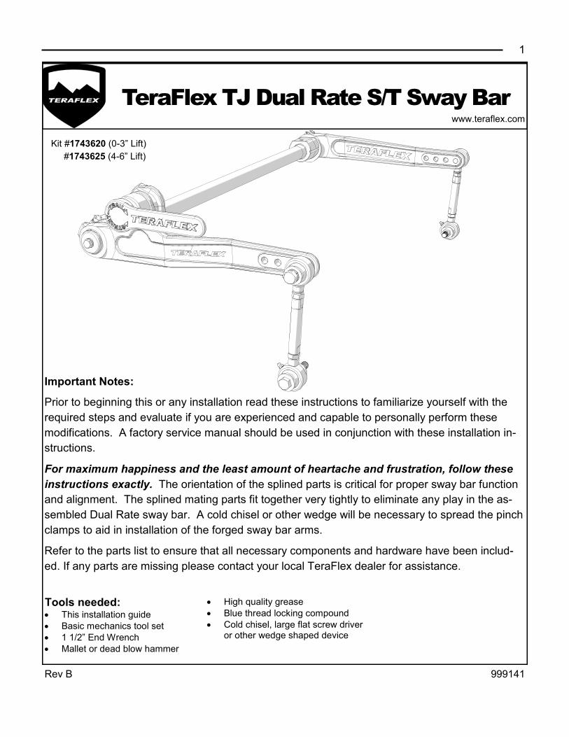
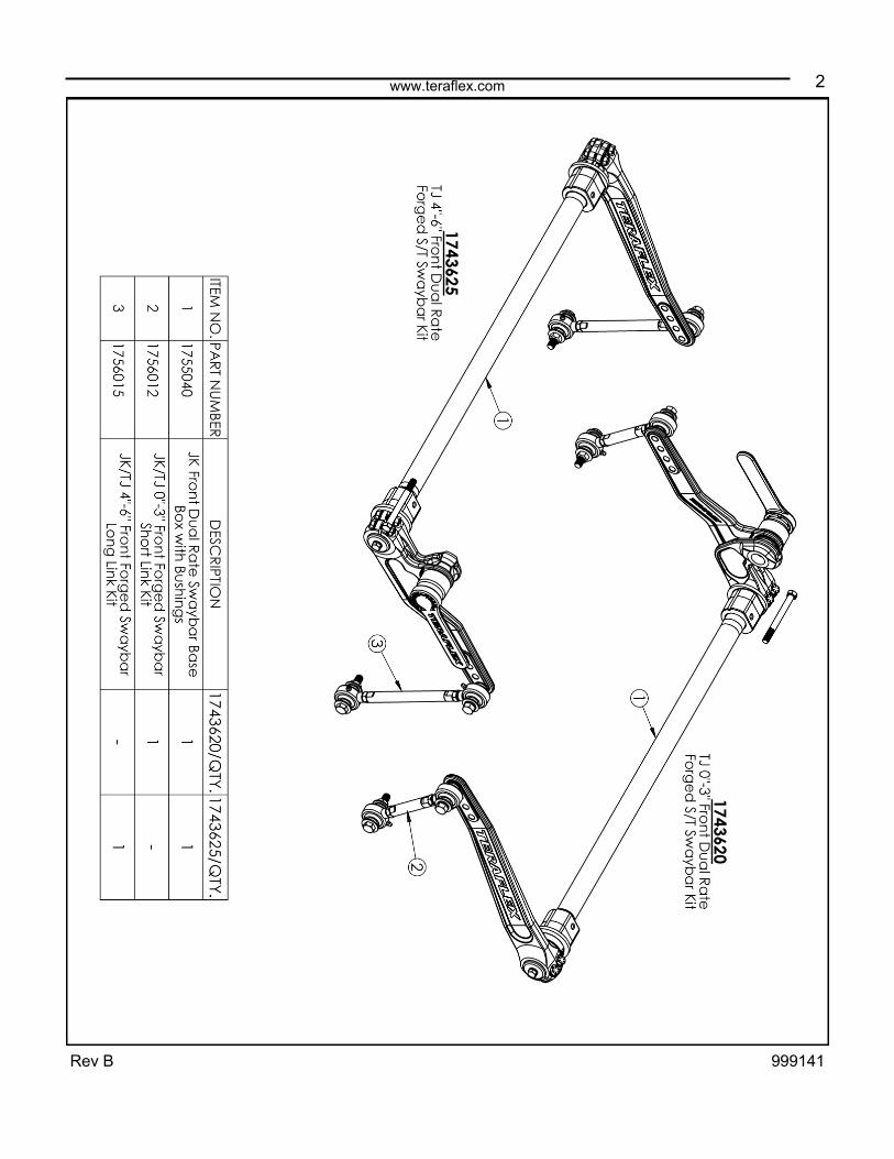
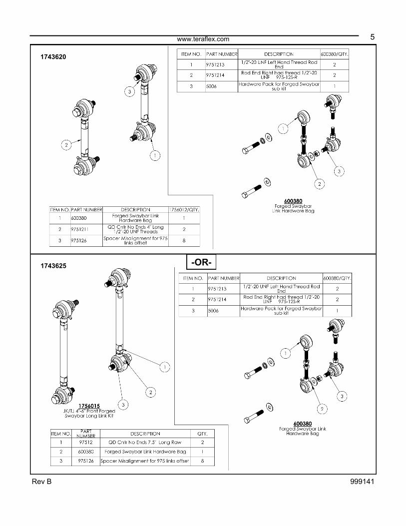
Kit #1743620 (0-3” Lift)
#1743625 (4-6” Lift)
Important Notes:
Prior to beginning this or any installation read these instructions to familiarize yourself with the
required steps and evaluate if you are experienced and capable to personally perform these
modifications. A factory service manual should be used in conjunction with these installation in-
structions.
For maximum happiness and the least amount of heartache and frustration, follow these
instructions exactly. The orientation of the splined parts is critical for proper sway bar function
and alignment. The splined mating parts fit together very tightly to eliminate any play in the as-
sembled Dual Rate sway bar. A cold chisel or other wedge will be necessary to spread the pinch
clamps to aid in installation of the forged sway bar arms.
Refer to the parts list to ensure that all necessary components and hardware have been includ-
ed. If any parts are missing please contact your local TeraFlex dealer for assistance.
www.teraflex.com
2
Rev B 999141
www.teraflex.com
3
Rev B 999141
www.teraflex.com
4
Rev B 999141
www.teraflex.com
5
Rev B 999141
-OR-
1743620
1743625
6 www.teraflex.com
Rev B 999141
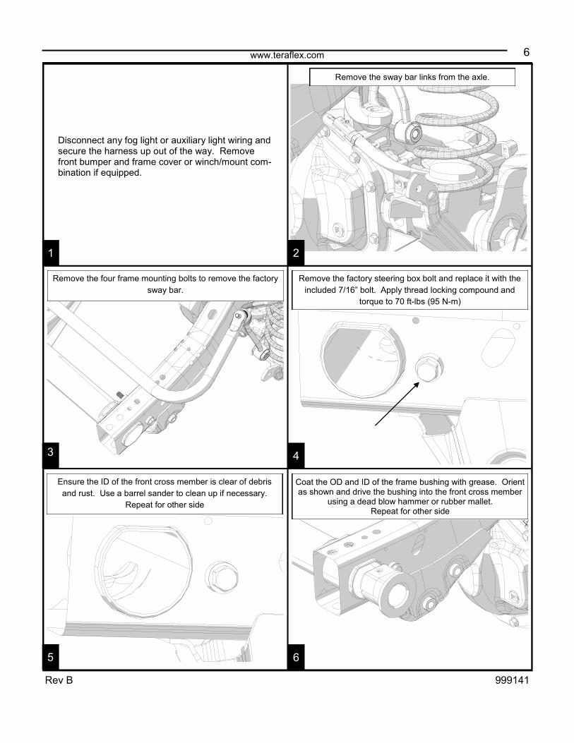
Disconnect any fog light or auxiliary light wiring and secure the harness up out of the way. Remove front bumper and frame cover or winch/mount com-bination if equipped.
1 2
6 5
4 3
Remove the four frame mounting bolts to remove the factory
sway bar.
Remove the factory steering box bolt and replace it with the
included 7/16” bolt. Apply thread locking compound and
torque to 70 ft-lbs (95 N-m)
Remove the sway bar links from the axle.
Coat the OD and ID of the frame bushing with grease. Orient as shown and drive the bushing into the front cross member
using a dead blow hammer or rubber mallet. Repeat for other side
Ensure the ID of the front cross member is clear of debris
and rust. Use a barrel sander to clean up if necessary.
Repeat for other side
7 www.teraflex.com
Rev B 999141
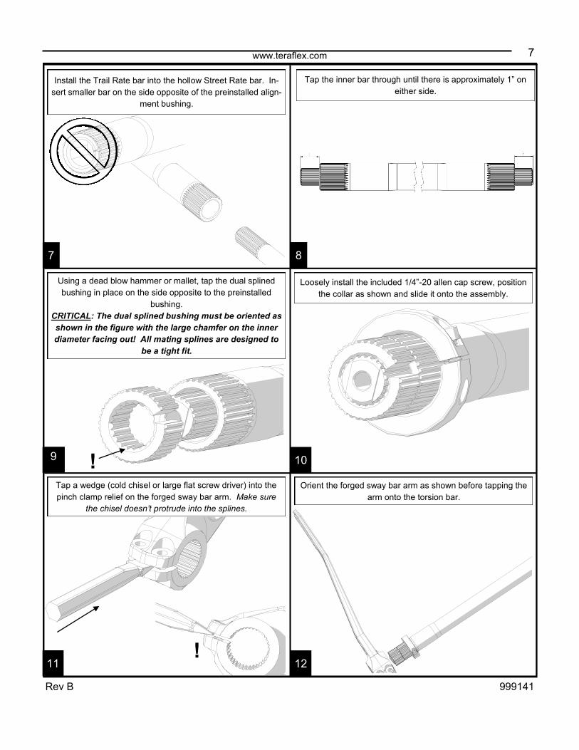
Orient the forged sway bar arm as shown before tapping the
arm onto the torsion bar.
7 8
12
10 9
11
Tap a wedge (cold chisel or large flat screw driver) into the
pinch clamp relief on the forged sway bar arm. Make sure
the chisel doesn’t protrude into the splines.
!
Install the Trail Rate bar into the hollow Street Rate bar. In-
sert smaller bar on the side opposite of the preinstalled align-
ment bushing.
Tap the inner bar through until there is approximately 1” on
either side.
Using a dead blow hammer or mallet, tap the dual splined
bushing in place on the side opposite to the preinstalled
bushing.
CRITICAL: The dual splined bushing must be oriented as
shown in the figure with the large chamfer on the inner
diameter facing out! All mating splines are designed to
be a tight fit.
!
Loosely install the included 1/4”-20 allen cap screw, position
the collar as shown and slide it onto the assembly.
8 www.teraflex.com
Rev B 999141
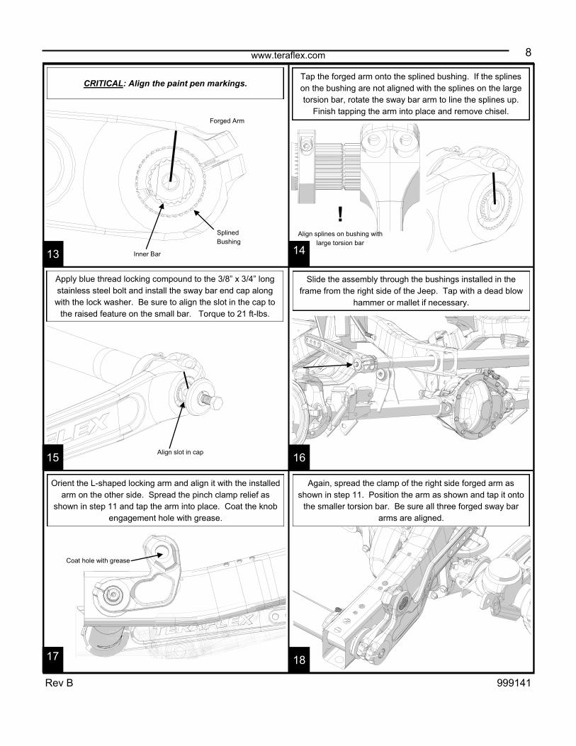
Slide the assembly through the bushings installed in the
frame from the right side of the Jeep. Tap with a dead blow
hammer or mallet if necessary.
13 14
17
16 15
18
CRITICAL: Align the paint pen markings.
Forged Arm
Inner Bar
Splined
Bushing
Tap the forged arm onto the splined bushing. If the splines
on the bushing are not aligned with the splines on the large
torsion bar, rotate the sway bar arm to line the splines up.
Finish tapping the arm into place and remove chisel.
!
Align splines on bushing with
large torsion bar
Apply blue thread locking compound to the 3/8” x 3/4” long
stainless steel bolt and install the sway bar end cap along
with the lock washer. Be sure to align the slot in the cap to
the raised feature on the small bar. Torque to 21 ft-lbs.
Align slot in cap
Orient the L-shaped locking arm and align it with the installed
arm on the other side. Spread the pinch clamp relief as
shown in step 11 and tap the arm into place. Coat the knob
engagement hole with grease.
Coat hole with grease
Again, spread the clamp of the right side forged arm as
shown in step 11. Position the arm as shown and tap it onto
the smaller torsion bar. Be sure all three forged sway bar
arms are aligned.
9 www.teraflex.com
Rev B 999141
19 20
22 21
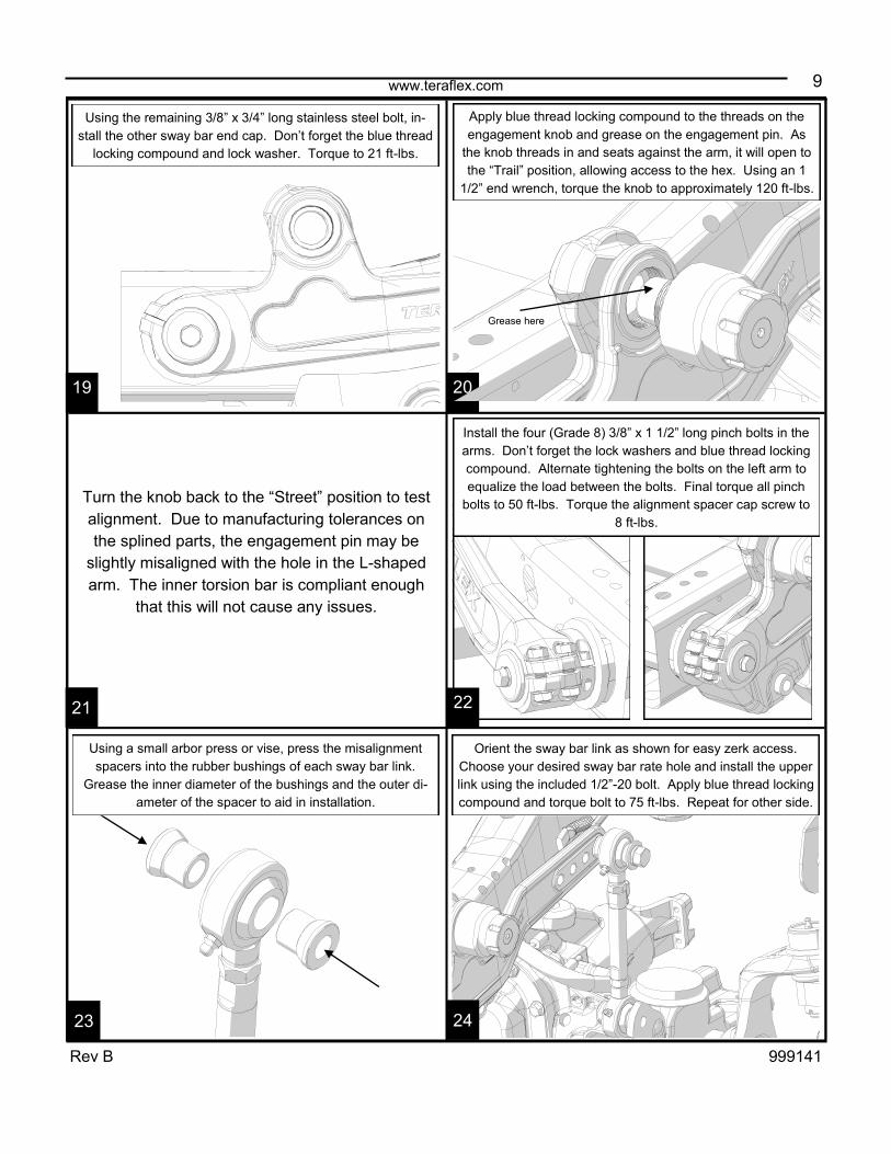
Using the remaining 3/8” x 3/4” long stainless steel bolt, in-
stall the other sway bar end cap. Don’t forget the blue thread
locking compound and lock washer. Torque to 21 ft-lbs.
Apply blue thread locking compound to the threads on the
engagement knob and grease on the engagement pin. As
the knob threads in and seats against the arm, it will open to
the “Trail” position, allowing access to the hex. Using an 1
1/2” end wrench, torque the knob to approximately 120 ft-lbs.
Grease here
Turn the knob back to the “Street” position to test
alignment. Due to manufacturing tolerances on
the splined parts, the engagement pin may be
slightly misaligned with the hole in the L-shaped
arm. The inner torsion bar is compliant enough
that this will not cause any issues.
Install the four (Grade 8) 3/8” x 1 1/2” long pinch bolts in the
arms. Don’t forget the lock washers and blue thread locking
compound. Alternate tightening the bolts on the left arm to
equalize the load between the bolts. Final torque all pinch
bolts to 50 ft-lbs. Torque the alignment spacer cap screw to
8 ft-lbs.
Orient the sway bar link as shown for easy zerk access.
Choose your desired sway bar rate hole and install the upper
link using the included 1/2”-20 bolt. Apply blue thread locking
compound and torque bolt to 75 ft-lbs. Repeat for other side.
Using a small arbor press or vise, press the misalignment
spacers into the rubber bushings of each sway bar link.
Grease the inner diameter of the bushings and the outer di-
ameter of the spacer to aid in installation.
23 24
10 www.teraflex.com
Rev B 999141
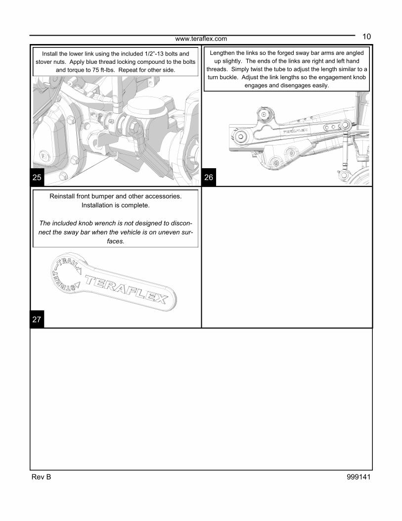
Install the lower link using the included 1/2”-13 bolts and
stover nuts. Apply blue thread locking compound to the bolts
and torque to 75 ft-lbs. Repeat for other side.
Lengthen the links so the forged sway bar arms are angled
up slightly. The ends of the links are right and left hand
threads. Simply twist the tube to adjust the length similar to a
turn buckle. Adjust the link lengths so the engagement knob
engages and disengages easily.
Reinstall front bumper and other accessories.
Installation is complete.
The included knob wrench is not designed to discon-
nect the sway bar when the vehicle is on uneven sur-
faces.
25 26
27
www.teraflex.com
11
Rev B 999141
TERAFLEX, Inc. 5680 West Dannon Way West Jordan, Utah 84081 Phone/801.713.3314 Fax/801.713.2313 www.teraflex.com
PRODUCT INFORMATION MAINTENANCE INFORMATION:
It is the buyer’s responsibility to have all suspension, drivetrain, steering, and other components checked for proper tightness and torque after the first 100 miles
and every 3000 miles after that.
NOTICE TO INSTALLER:
The enclosed “Warning to Driver” sticker must be installed in the vehicle in driver’s view. This sticker is to act as a constant safety reminder when operating the
vehicle. It is your responsibility as the equipment installer to install the provided sticker and to forward the product instructions to the vehicle’s owner for review. If
a “Warning to Driver” sticker or product installation guide were not included in the kit, FREE replacement stickers and instructions are available by request. It is the
installer’s duty to ensure a safe and controllable vehicle after the modifications have been performed.
WARNING:
Neither the seller nor the manufacturer will be liable for any loss, damage, or injury directly or indirectly arising from the use of or inability to determine the use of
these products. Before using, the user shall determine the suitability of the products for its intended use, and the user shall assume all responsibility and risk in
connection therewith.
WARNING TO DRIVER:
This vehicle has been modified to enhance off road performance and has unique handling characteristics. Use in harsh environments can cause extreme stress
on the components. Vehicle should be inspected after being off road to make sure that all the components are in working order and safe to travel on the highway.
All fasteners should be checked so that they are at the correct torque specifications as the vibration and stresses from off roading may cause critical fasteners to
work loose. Extra care should be taken to inspect the critical components, steering, and brake systems. During each oil change components such as arms, tie rod
ends, etc should be greased and checked for excessive wear. Any worn components should be replaced. When returning to the pavement always set or restore
tire air pressure to the factory recommendation and connect or engage any disabled sway bar mechanisms. Because of the higher center of gravity and larger
tires, this vehicle handles and reacts differently than many passenger cars, both on and off road. You must drive it safely! Extreme care should be taken to pre-
vent vehicle rollover or loss of control, which can result in serious injury or death. Avoid sudden sharp turns or abrupt maneuvers. Generally, braking performance
and capabilities are decreased when significantly larger/heavier tires are used, especially when used in combination with transfer case low-range reduction kits.
Take this into consideration while driving. Do not add, alter or fabricate any factory or aftermarket parts to increase vehicle height over the intended height of the
TeraFlex product purchased. Mixing component brand is not recommended. TeraFlex Inc. will not be responsible for any altered product or any improper installa-
tion or use of our products. We will be happy to answer any questions concerning the design, function, and correct use of our products. It is ultimately the buyer’s
responsibility to have all bolts/nuts checked for tightness after the first 100 miles and then every 3000 miles. Wheel alignment, steering system, suspension and
drive line systems must be inspected by a qualified professional mechanic at least every 3000 miles.
TERAFLEX PRODUCT WARRANTY:
TeraFlex Inc. warrants TeraFlex Suspension products to the original retail purchaser to be free of defects in material and workmanship for as long as the original
purchaser owns the vehicle on which products were originally installed.
Failure to complete regular maintenance (grease every 3000 miles) on TeraFlex FlexArms will void this warranty. All other conditions of the standard TeraFlex
product warranty apply.
All TeraLow products are covered by the TeraFlex two (2) year warranty to be free of defects in material and workmanship for two years from date purchased.
TeraFlex axles are covered by a 12-month warranty to be free of defects in materials and workmanship.
This warranty does not cover or include product finish, improperly installed or applied products, improperly maintained products, products or components used for
racing or competition or damage due to abuse or neglect, products that fail due to the use of larger tire and wheel combinations.
All returns must be accompanied by an original invoice. It is the customer’s responsibility to remove the product from the vehicle. Shipping charges are the re-
sponsibility of the customer. TeraFlex Inc. will pay the return freight if the product meets the terms of warranty.
This warranty is for the replacement or repair of defective TeraFlex products only and does not include freight charges, labor charges for removal of or installation
of TeraFlex or related products or components, costs incurred due to down time of the vehicle, or lost profits due to vehicle down time.
A returned goods authorization number (RGA#) must accompany any returned products. For more information please contact a TeraFlex customer service repre-
TeraFlex® is a registered trademark of TeraFlex Inc. All trade names and logos including but not limited to TeraFlex, FlexArms, RockGuard, Monster, and
LCG are protected by law and duplication of trade names and/or logos are strictly prohibited.
TeraFlex Inc. reserves the right to update, discontinue, redesign, modify finish, part number or component build parts if deemed necessary without written notice.
TeraFlex Inc., and any associated dealers are not responsible for misprints or typographical errors that may have inadvertently been made within this instruction
sheet.
Jeep® and the Jeep® grill are registered trademarks of Fiat Chrysler Automobiles N.V., and have no affiliation with TeraFlex Inc.


![Tom&Jerry-Katalog WEB draft0 rev4-small - TJ Labels sticky notes ppp tj-cherry zez tj-bird tj-car tj-fruit model flags t]-garden tj-candy tj-sea](https://static.documents.pub/doc/80x56/5ae5d4947f8b9a9e5d8cec91/tomjerry-katalog-web-draft0-rev4-small-tj-sticky-notes-ppp-tj-cherry-zez-tj-bird.jpg)


