Terminale Gnl Adriatico Srl Marine Operations Manual Table of Contents March 2017 i Revision 1.0 Table of Contents 1.0 Introduction....................................................................................................... 1-1 1.1 Using This Document ............................................................................... 1-2 1.2 Code of Safe Working Practices ............................................................... 1-5 1.3 Industry References and Guidelines ......................................................... 1-6 1.4 Exceptions, Updates, and Management of Change................................... 1-8 2.0 General Information ......................................................................................... 2-1 2.1 Vessel Types ............................................................................................. 2-2 2.2 Marine Support Operations, Position Titles, Key Responsibilities........... 2-4 2.3 Marine Resources and Reviews ................................................................ 2-8 3.0 Vessel Selection and Contracting .................................................................... 3-1 3.1 Requisition ................................................................................................ 3-3 3.2 Vessel Operator Pre-Qualification ............................................................ 3-7 3.2.1 Identifying Potential Bidders ....................................................... 3-8 3.2.2 Vessel Operator Pre-qualification Process................................... 3-9 3.2.3 Safety Performance .................................................................... 3-10 3.2.4 Use of OCIMF OVMSA ............................................................ 3-11 3.2.5 Qualification Criteria ................................................................. 3-13 3.2.6 Gap Closures .............................................................................. 3-14 3.3 Technical Bid Package............................................................................ 3-15 3.4 The Technical Evaluation ....................................................................... 3-16 3.5 Vessel Inspections................................................................................... 3-18 3.6 Spot-Hire Vessels ................................................................................... 3-21 3.7 Fuel Barge or Tanker Hire ...................................................................... 3-22 3.8 Contactor Interface.................................................................................. 3-23 3.9 Tools ....................................................................................................... 3-25 4.0 Safety, Security, Health, and Environment .................................................... 4-1 4.1 Safety Management Systems .................................................................... 4-2 4.2 Crew Manning and Training ..................................................................... 4-4 4.3 Personal Protective Equipment (PPE)....................................................... 4-7 4.4 Risk Management ..................................................................................... 4-8 4.5 Health Management ................................................................................ 4-10 4.6 Pollution Prevention ............................................................................... 4-13 4.7 Incident Reporting and Investigation ...................................................... 4-14 4.8 Emergency Response .............................................................................. 4-16 4.9 International Ship and Port Facility Security (ISPS) Code ..................... 4-17 5.0 Marine Operations............................................................................................ 5-1 5.1 Communications ....................................................................................... 5-3 5.2 Onboard Documentation Requirements .................................................. 5-10 5.3 Port Requirements, Passage Planning and Navigation ........................... 5-13
Transcript
Terminale Gnl Adriatico Srl Marine Operations Manual Table of Contents
March 2017 i Revision 1.0
Table of Contents 1.0 Introduction ....................................................................................................... 1-1
1.1 Using This Document ............................................................................... 1-2 1.2 Code of Safe Working Practices ............................................................... 1-5 1.3 Industry References and Guidelines ......................................................... 1-6 1.4 Exceptions, Updates, and Management of Change ................................... 1-8
2.0 General Information ......................................................................................... 2-1
2.1 Vessel Types ............................................................................................. 2-2 2.2 Marine Support Operations, Position Titles, Key Responsibilities ........... 2-4 2.3 Marine Resources and Reviews ................................................................ 2-8
3.0 Vessel Selection and Contracting .................................................................... 3-1
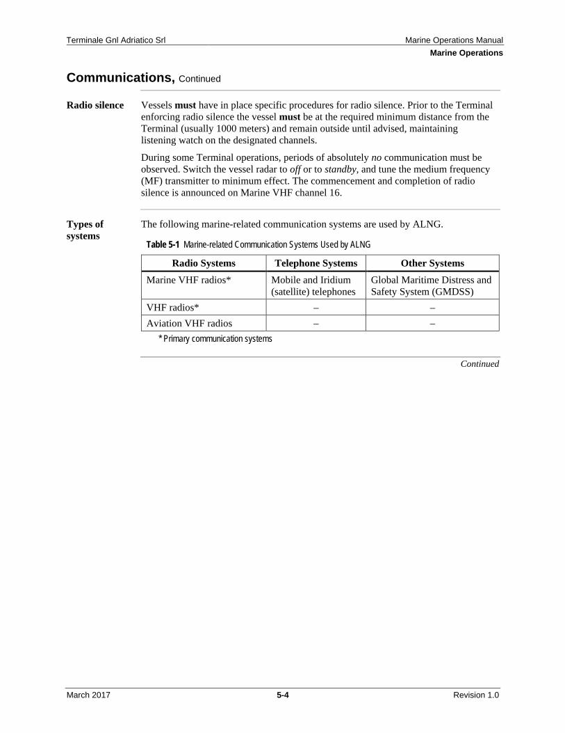
5.1 Communications ....................................................................................... 5-3 5.2 Onboard Documentation Requirements .................................................. 5-10 5.3 Port Requirements, Passage Planning and Navigation ........................... 5-13
Terminale Gnl Adriatico Srl Marine Operations Manual Table of Contents
March 2017 ii Revision 1.0
5.3.1 Local Harbor Master and Port Requirements ............................ 5-14 5.3.2 Passage Planning and Navigation .............................................. 5-15
5.5 Operations Near the Terminal and in the Safety Zone ............................ 5-20 5.6 In Port or Shore Base Operations ............................................................ 5-28 5.7 Tank Cleaning and Enclosed Space Entry .............................................. 5-30 5.8 Engine Room Operations ........................................................................ 5-31 5.9 Fuel Management ................................................................................... 5-34 5.10 Marine Vessel and Crew Requirements .................................................. 5-36
5.13.1 Tug Vessel Departure Procedures .............................................. 5-50 5.13.2 Tug En Route and Arrival Procedures ....................................... 5-53 5.13.3 Tug Offshore Site Departure Procedures ................................... 5-55 5.13.4 Tug Standby Operations during LNGC Offloading Operations 5-56 5.13.5 Firefighting ................................................................................ 5-59 5.13.6 Training and Exercises ............................................................... 5-62
5.14 Line Handler Boat Operations ................................................................ 5-64 5.14.1 Line Handler Boat Departure Procedures .................................. 5-65 5.14.2 En Route and Arrival Procedures .............................................. 5-68 5.14.3 Offshore Site Departure Procedures .......................................... 5-70 5.14.4 Transfer of Line Handling Crew to and from the Terminal ....... 5-71
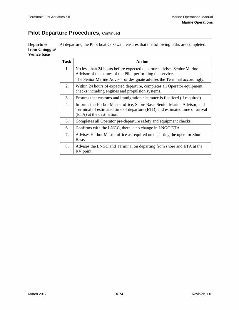
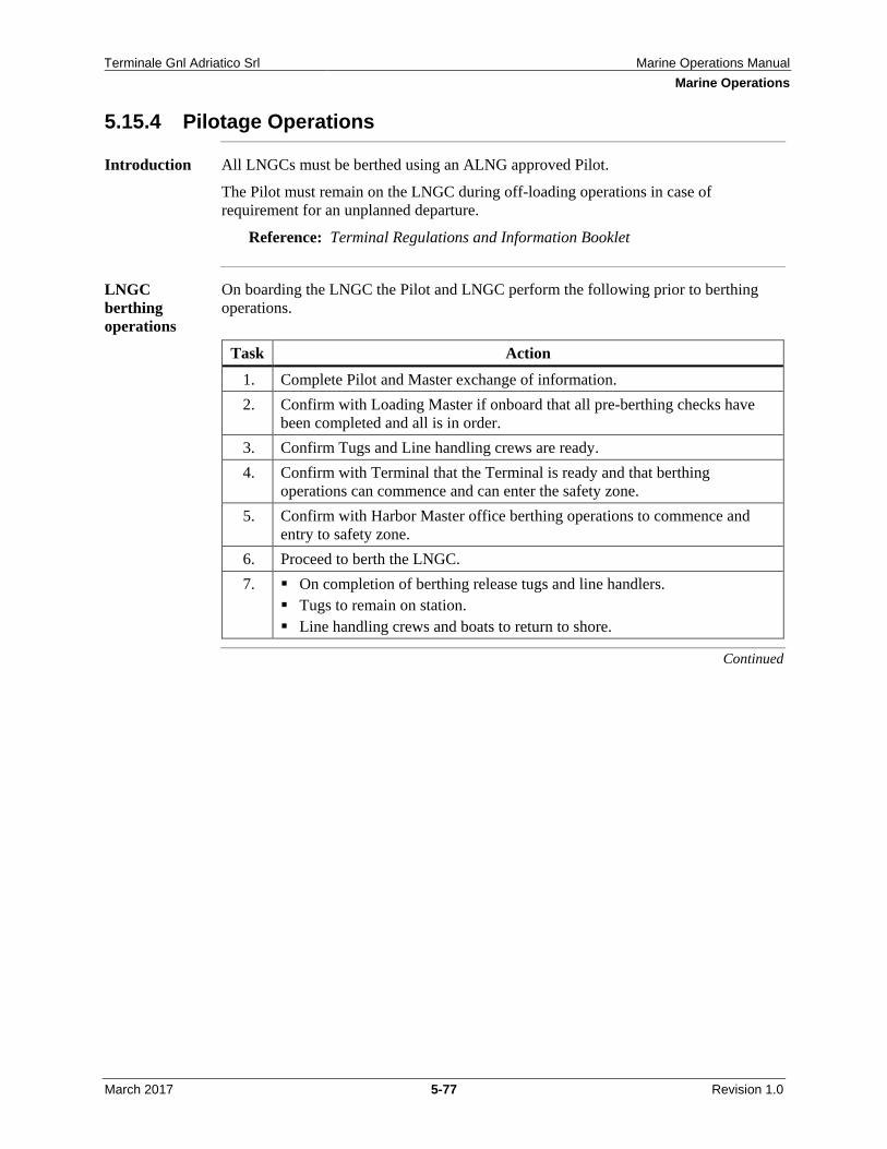
5.15 LNGC Pilot Boat .................................................................................... 5-72 5.15.1 Pilot Boat Departure Procedures ................................................ 5-73 5.15.2 En Route and Arrival Procedures .............................................. 5-75 5.15.3 Offshore Site Departure Procedures .......................................... 5-76 5.15.4 Pilotage Operations .................................................................... 5-77
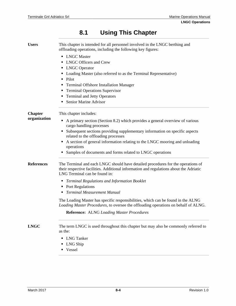
8.1 Using This Chapter ................................................................................... 8-4 8.2 Cargo Handling ......................................................................................... 8-5
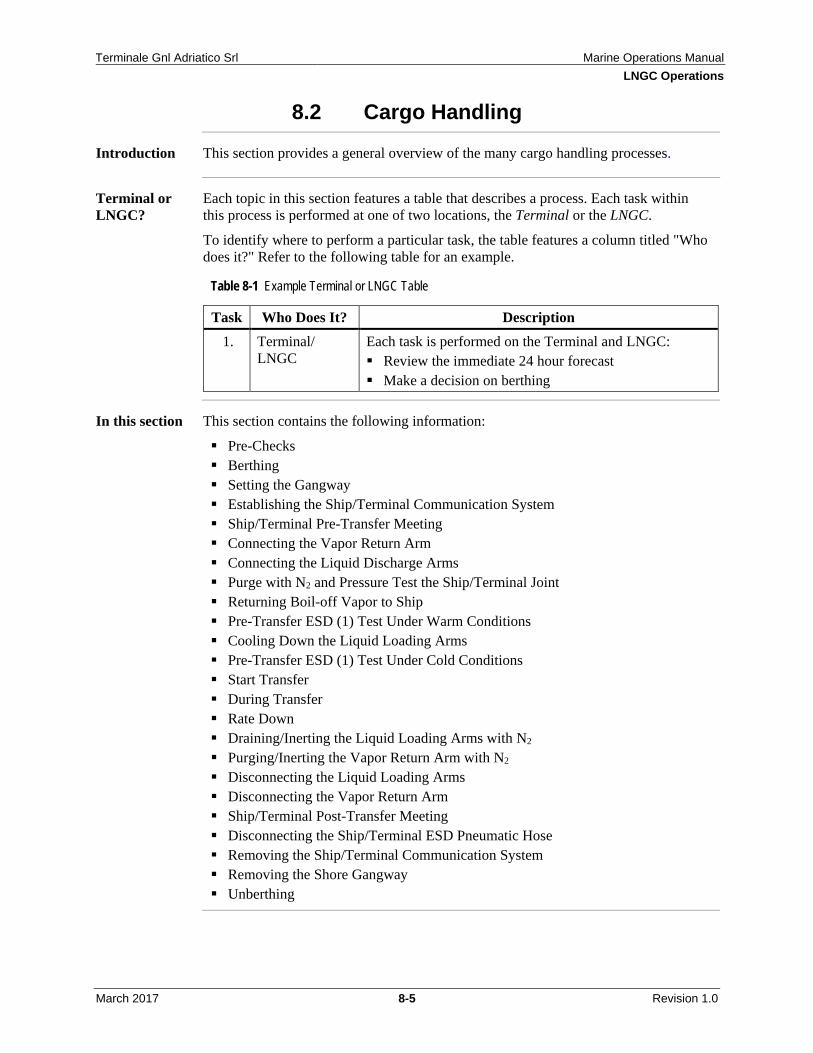
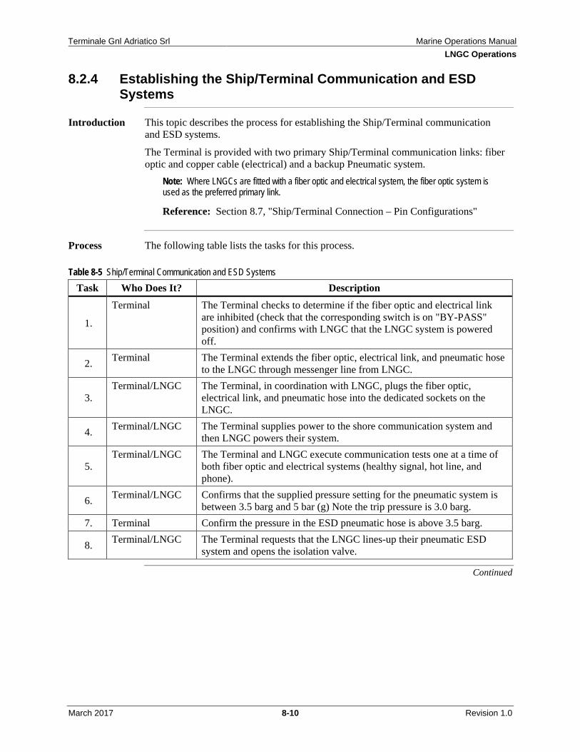
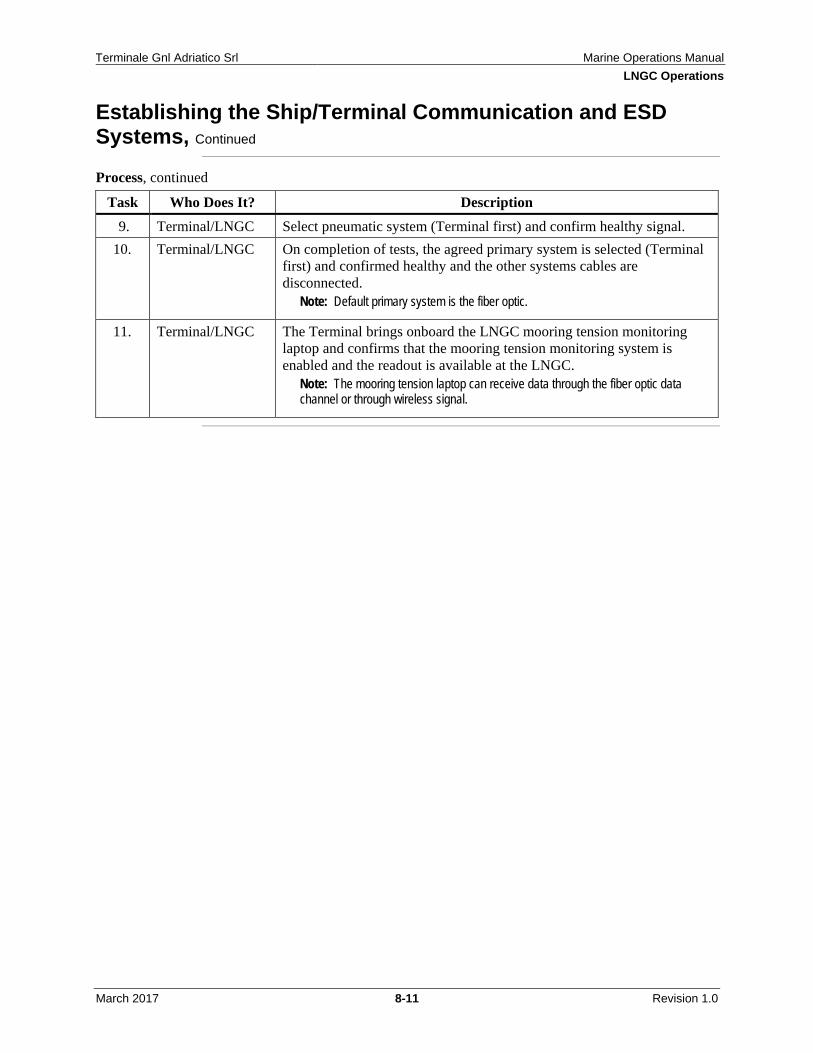
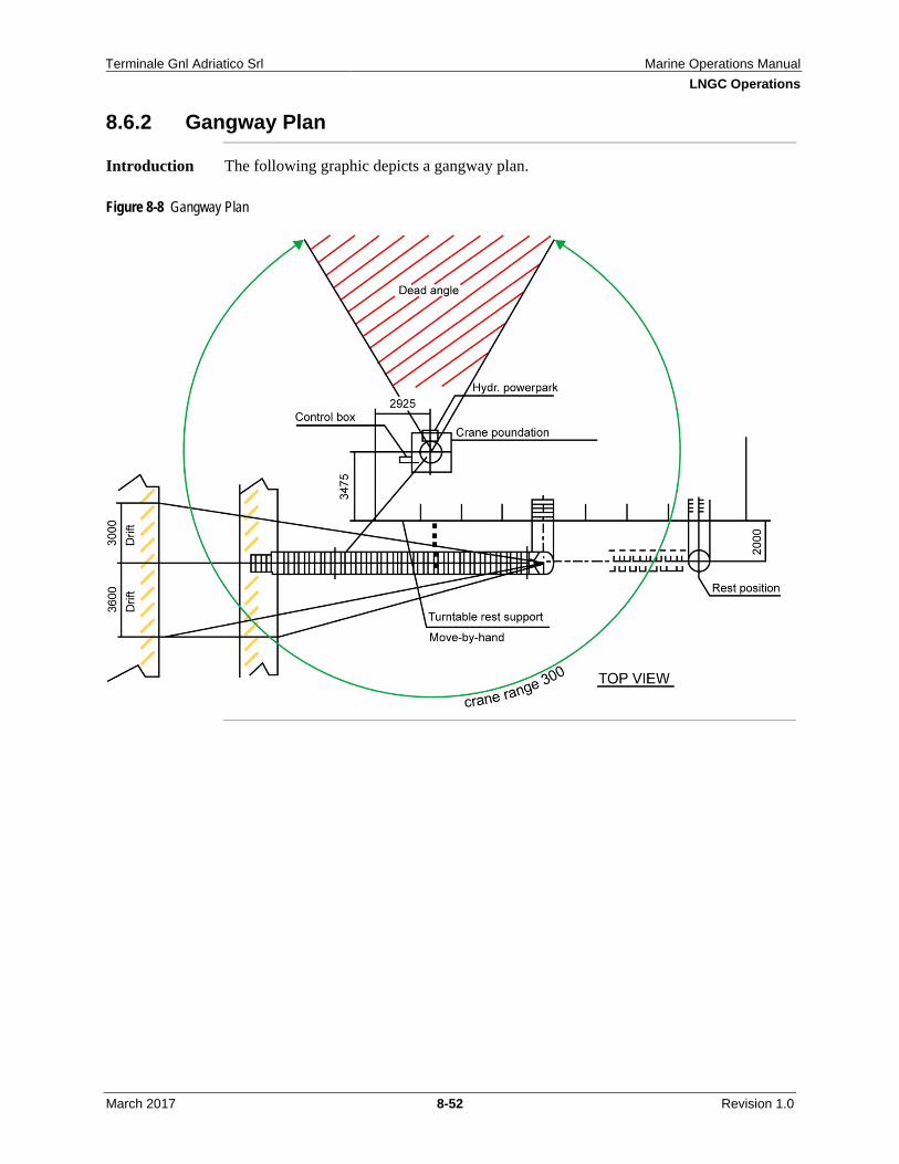
8.2.1 Pre-Checks ................................................................................... 8-6 8.2.2 Berthing ....................................................................................... 8-7 8.2.3 Setting the Gangway .................................................................... 8-9 8.2.4 Establishing the Ship/Terminal Communication and ESD
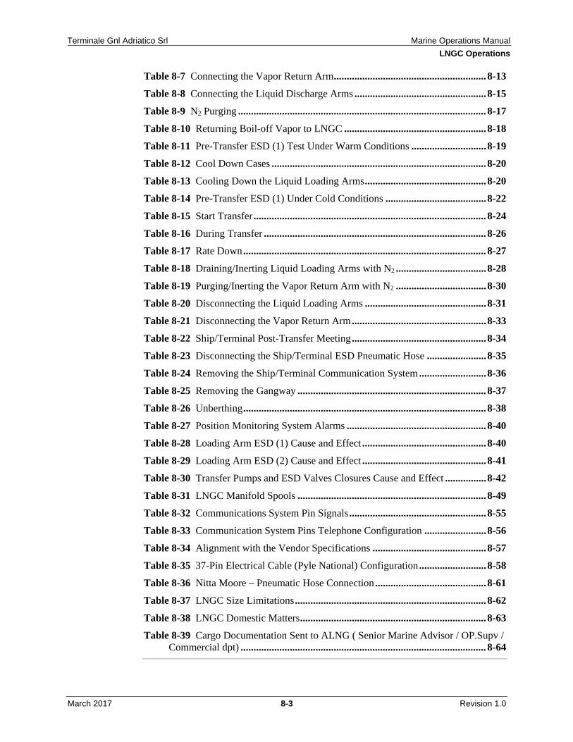
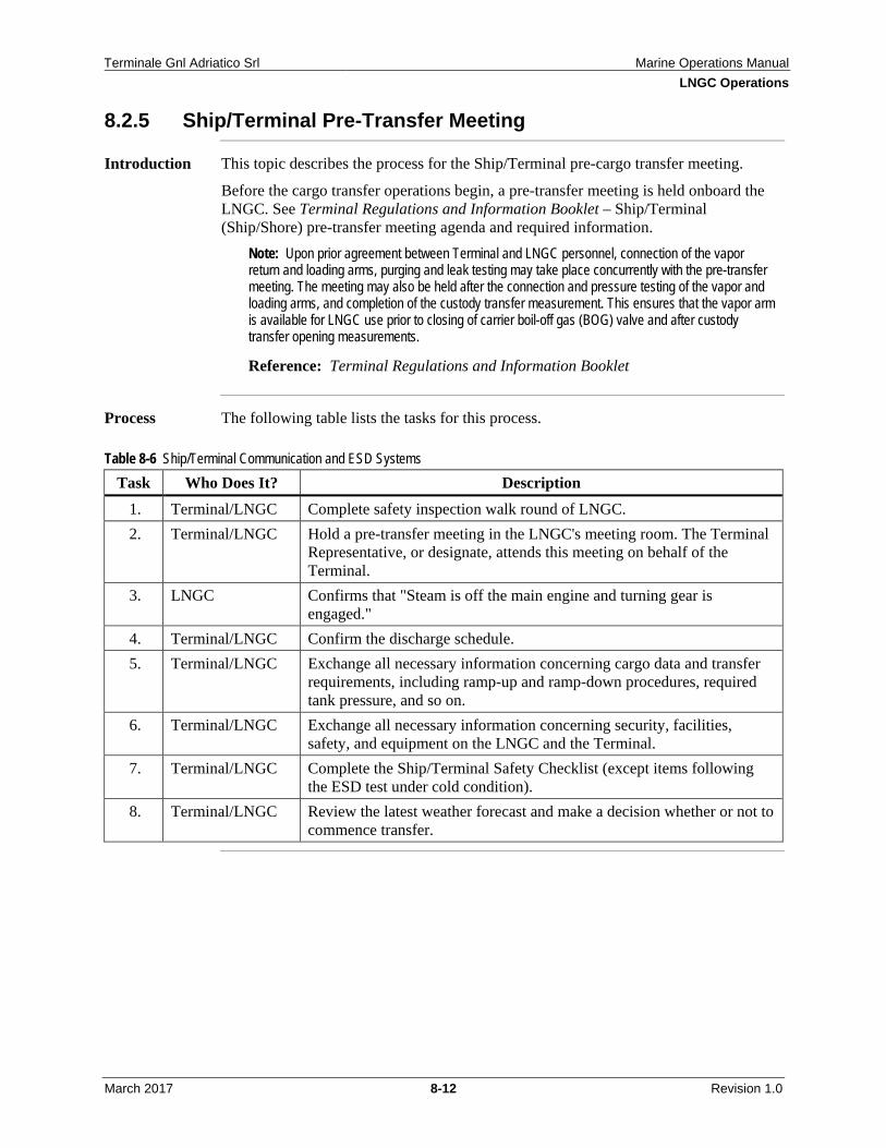
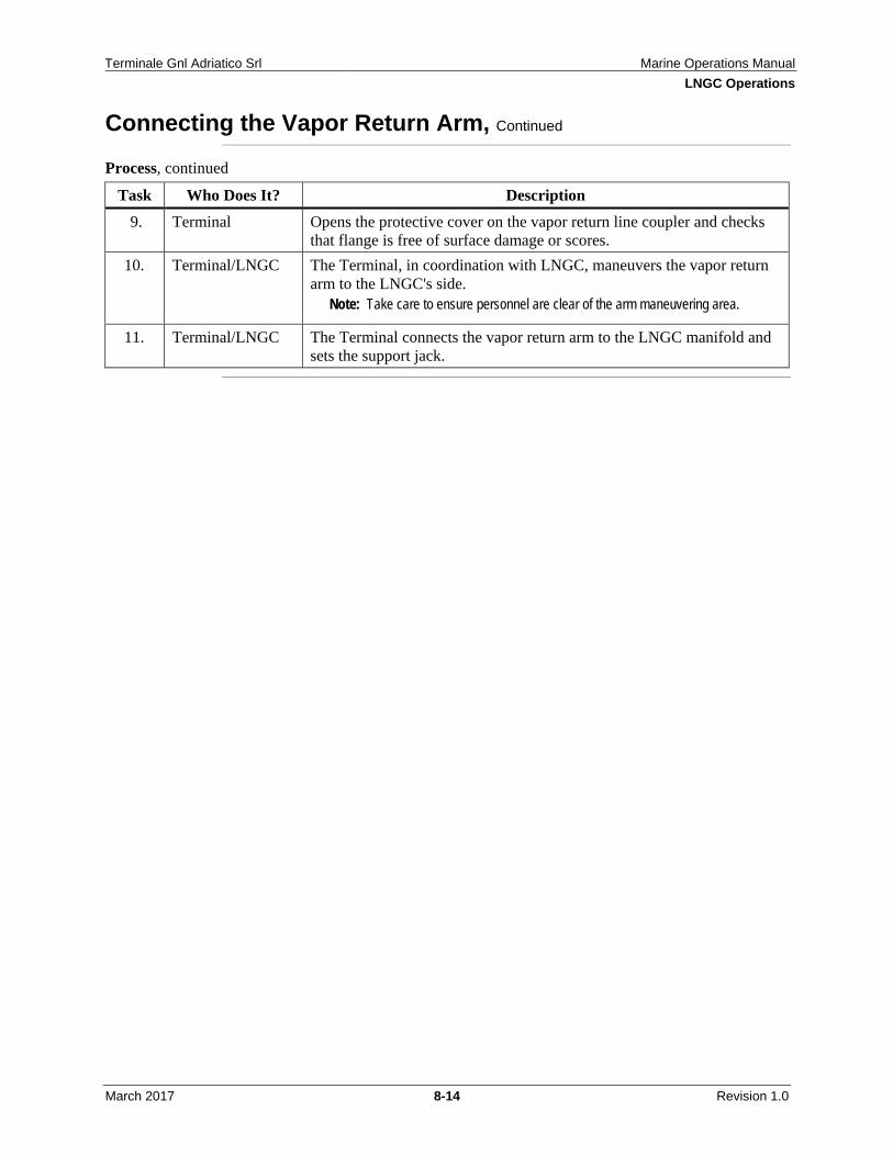
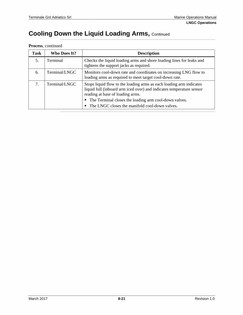
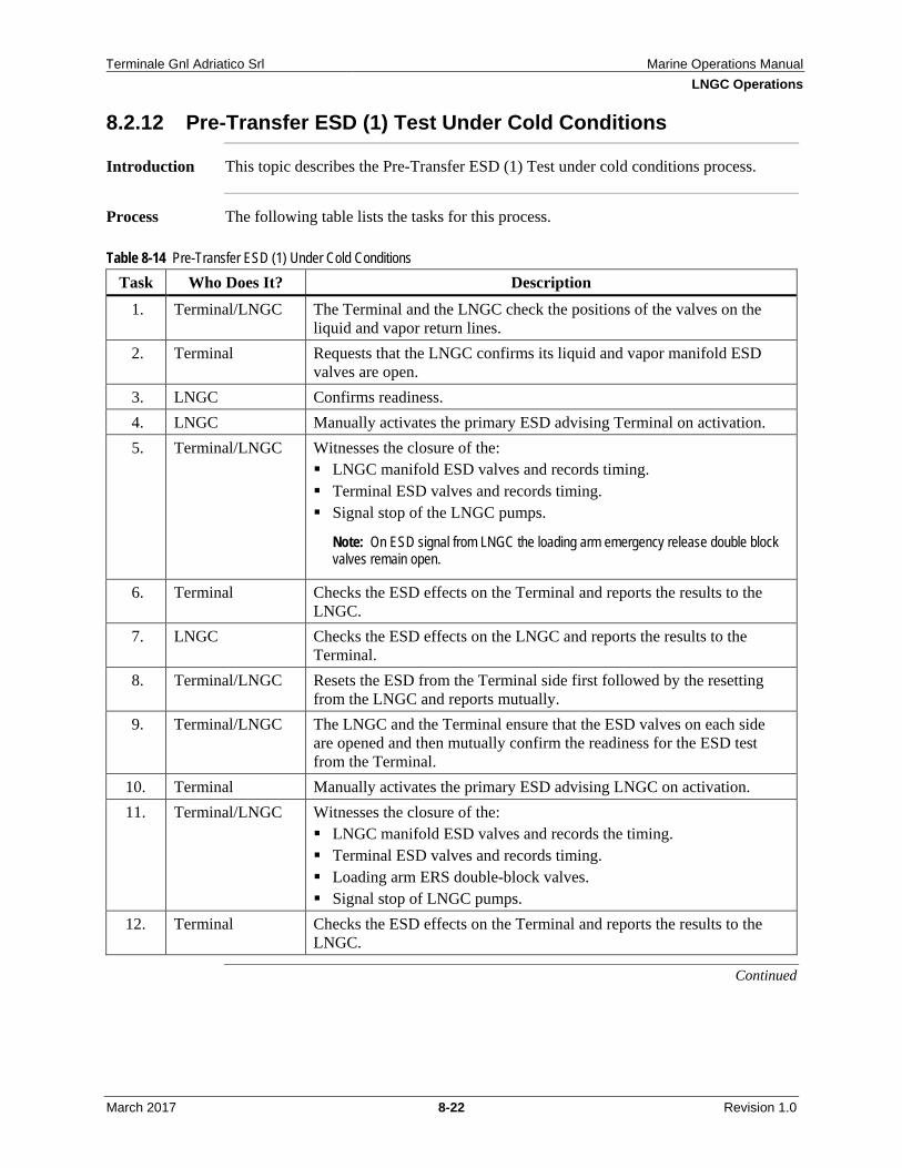
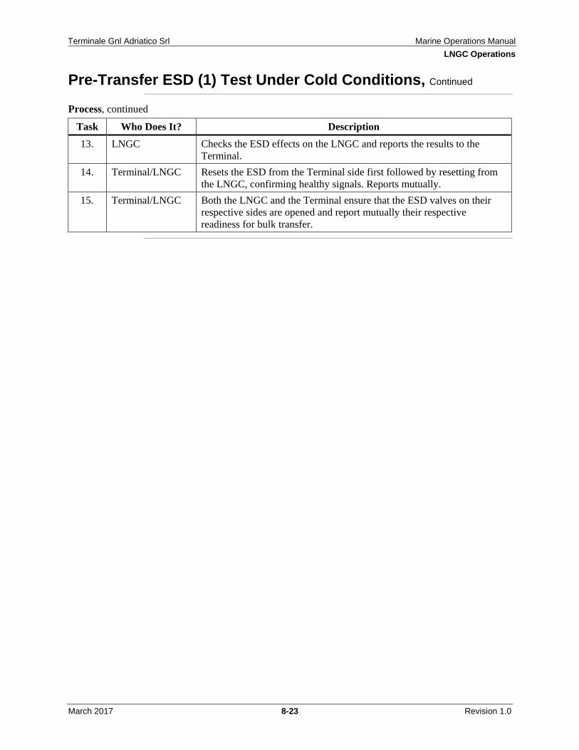
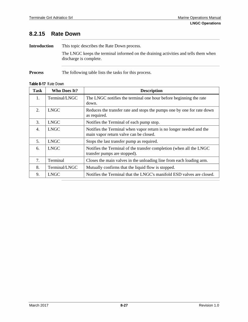
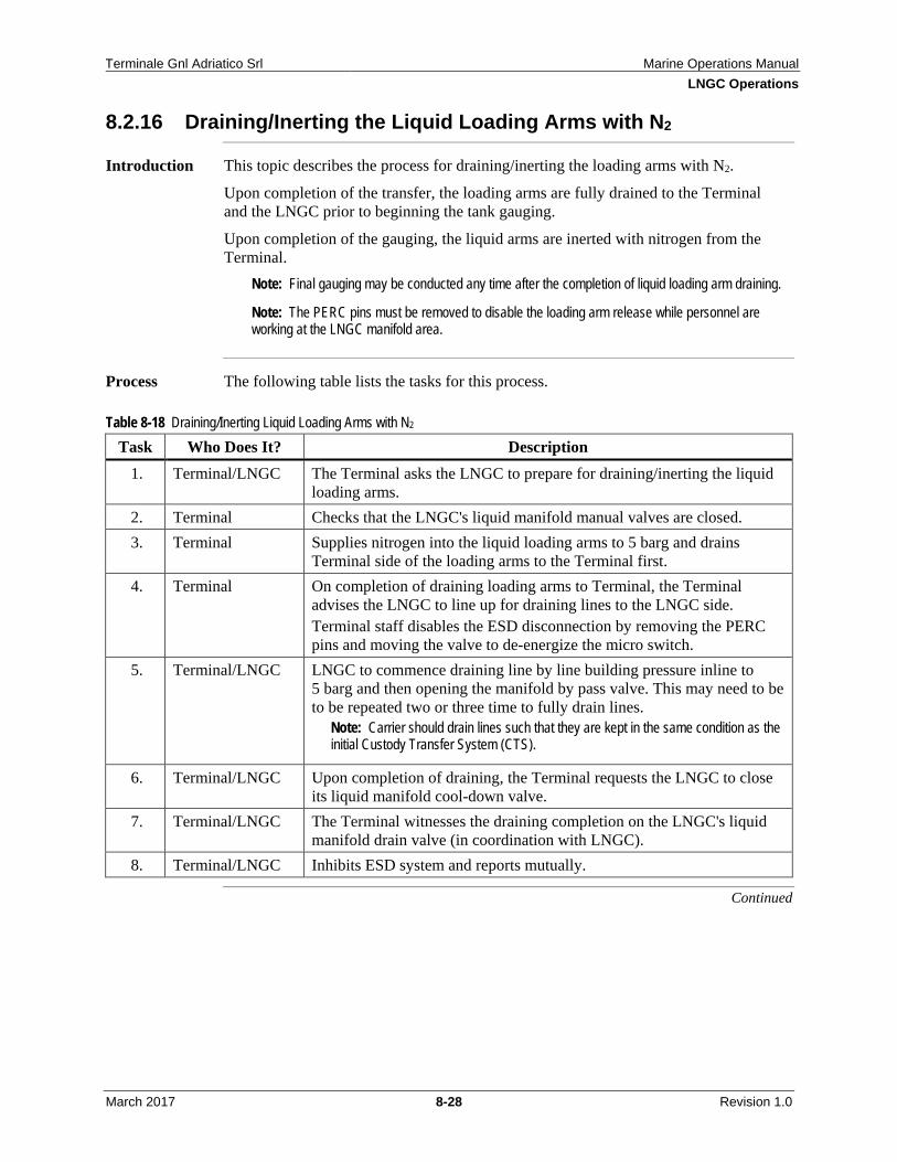
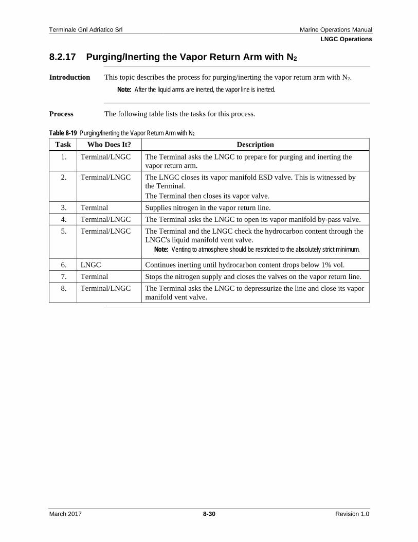
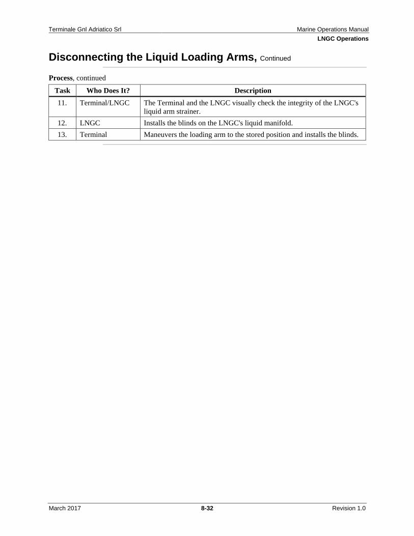
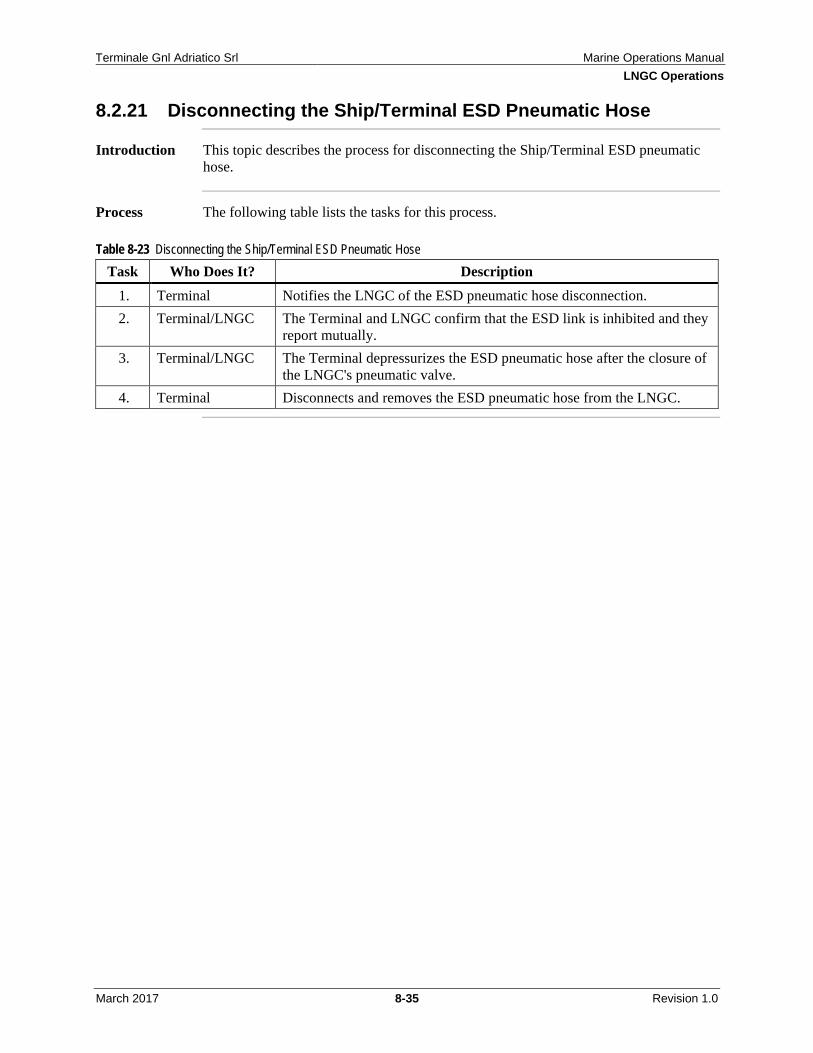
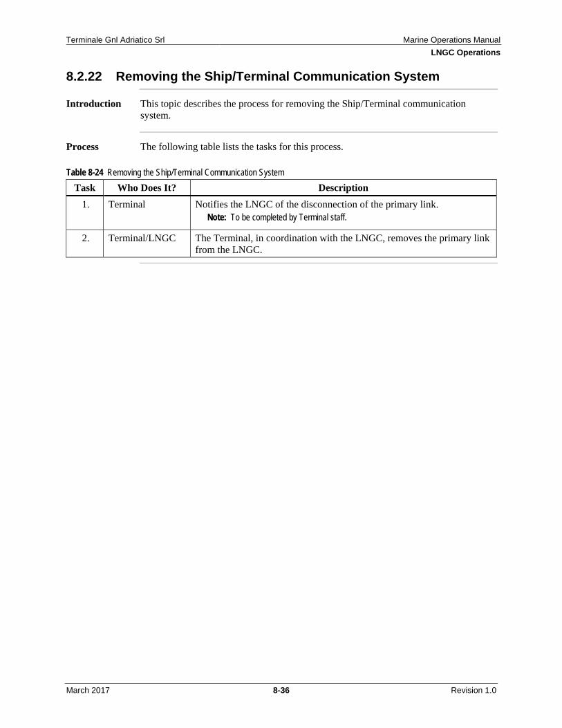
Systems ...................................................................................... 8-10 8.2.5 Ship/Terminal Pre-Transfer Meeting ......................................... 8-12 8.2.6 Connecting the Vapor Return Arm ............................................ 8-13 8.2.7 Connecting the Liquid Discharge Arms .................................... 8-15 8.2.8 Purge with N2 and Leak Test the Ship/Terminal Joint ............... 8-17 8.2.9 Returning Boil-off Vapor to LNGC ........................................... 8-18 8.2.10 Pre-Transfer ESD (1) Test Under Warm Conditions ................. 8-19 8.2.11 Cooling Down the Liquid Loading Arms .................................. 8-20 8.2.12 Pre-Transfer ESD (1) Test Under Cold Conditions ................... 8-22 8.2.13 Start Transfer ............................................................................. 8-24 8.2.14 During Transfer .......................................................................... 8-26 8.2.15 Rate Down ................................................................................. 8-27 8.2.16 Draining/Inerting the Liquid Loading Arms with N2 ................. 8-28 8.2.17 Purging/Inerting the Vapor Return Arm with N2 ....................... 8-30 8.2.18 Disconnecting the Liquid Loading Arms ................................... 8-31 8.2.19 Disconnecting the Vapor Return Arm ....................................... 8-33 8.2.20 Ship/Terminal Post-Transfer Meeting ....................................... 8-34 8.2.21 Disconnecting the Ship/Terminal ESD Pneumatic Hose ........... 8-35 8.2.22 Removing the Ship/Terminal Communication System ............. 8-36 8.2.23 Removing the Gangway ............................................................. 8-37 8.2.24 Unberthing ................................................................................. 8-38
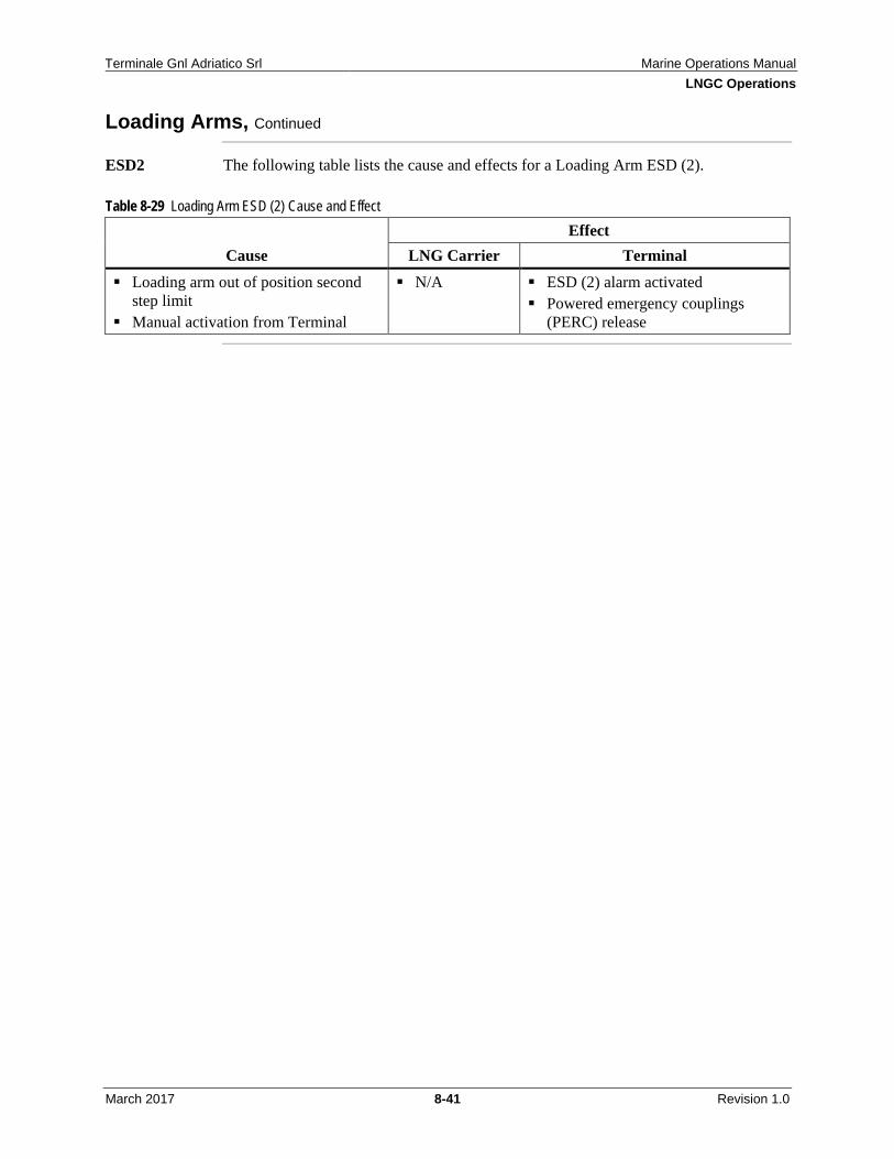
8.3 ESD Cause and Effects ........................................................................... 8-39 8.3.1 Loading Arms ............................................................................ 8-40 8.3.2 Terminal/LNGC Activated ESD ................................................ 8-42
8.4 Liquid and Vapor Line Operating Envelopes ......................................... 8-43 8.5 LNG Loading Arm Connection Assistance System ............................... 8-45
Terminale Gnl Adriatico Srl Marine Operations Manual Table of Contents
March 2017 iv Revision 1.0
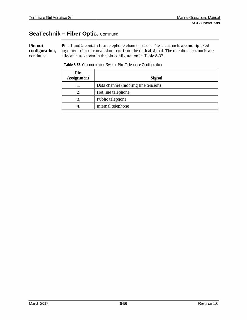
8.7.1 SeaTechnik – Fiber Optic .......................................................... 8-55 8.7.2 SeaTechnik – Electric Wire Link ............................................... 8-57 8.7.3 Nitta Moore – Pneumatic Hose Connection .............................. 8-61
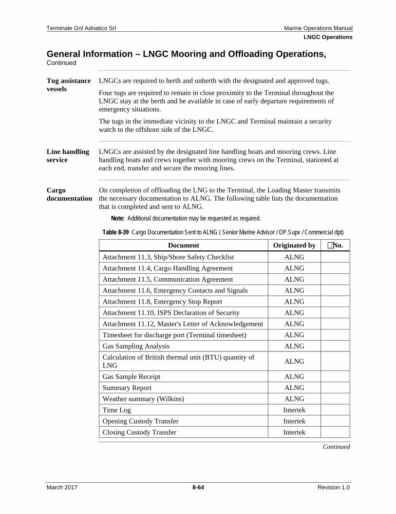
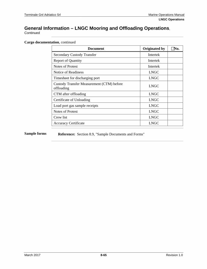
8.8 General Information – LNGC Mooring and Offloading Operations ...... 8-62 8.9 Pre-Transfer Meeting Agenda ................................................................. 8-66
9.0 Management of Change .................................................................................... 9-1
10.0 LNGC Vetting and Acceptance ..................................................................... 10-1
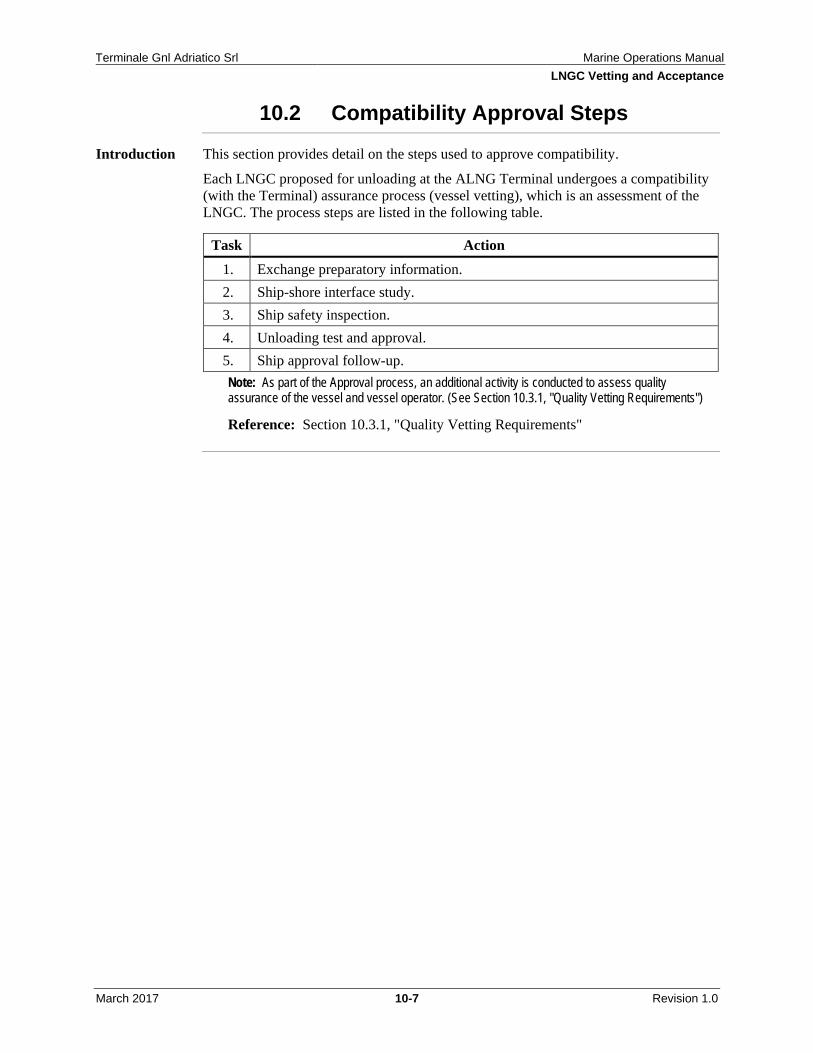
10.1 General Information on LNGC Approval Procedures ............................ 10-3 10.2 Compatibility Approval Steps ................................................................. 10-7
Figure 3-1 Links Between Contractor Selection and Management Focus Areas and OCIMF Elements .............................................................................................. 3-12
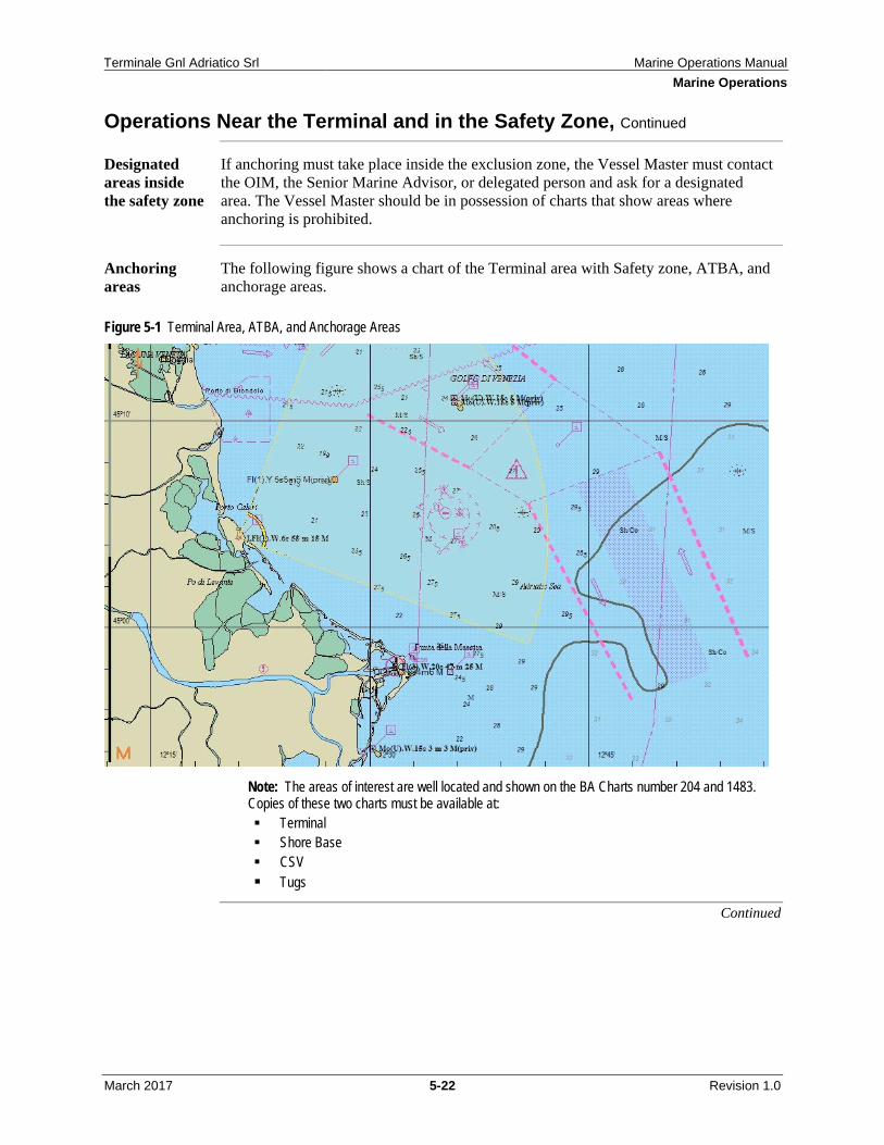
Figure 5-1 Terminal Area, ATBA, and Anchorage Areas ........................................ 5-22
Figure 5-2 Safety Zone Monitoring .......................................................................... 5-57
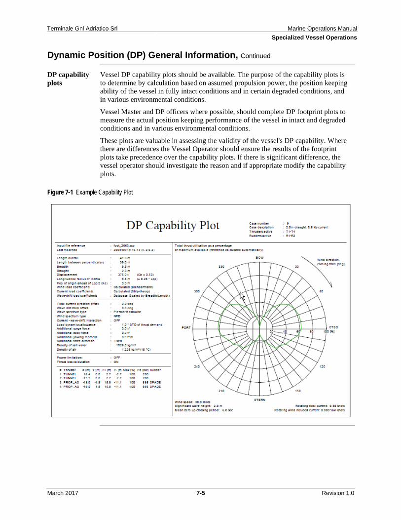
Figure 7-1 Example Capability Plot ........................................................................... 7-5
Figure 8-1 LNGC Ramp Up / Ramp Down Schedule .............................................. 8-25
Terminale Gnl Adriatico Srl Marine Operations Manual Table of Contents
March 2017 v Revision 1.0
Figure 8-2 Loading Arm Envelopes – Plan .............................................................. 8-43
Figure 8-3 Loading Arm Envelope – Elevation ....................................................... 8-44
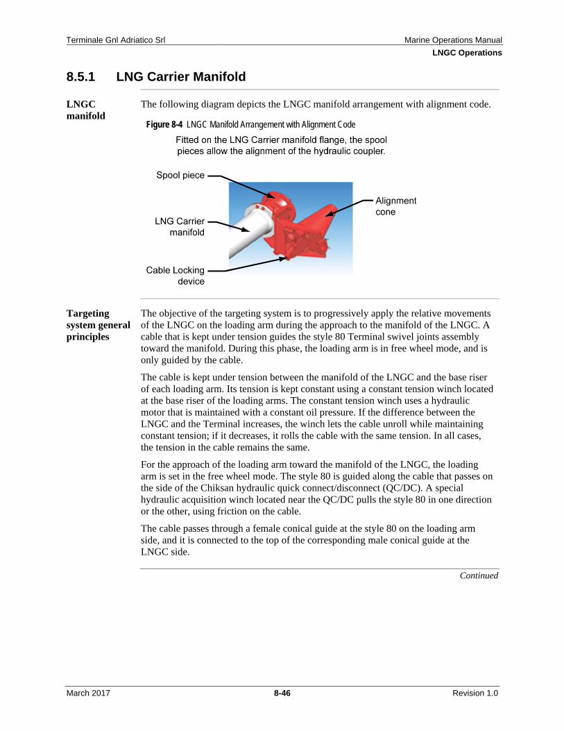
Figure 8-4 LNGC Manifold Arrangement with Alignment Code ............................ 8-46
Figure 8-5 Loading Arm and Major Components .................................................... 8-48
Figure 8-6 Typical Configuration with Spools at LNGC Manifolds ........................ 8-49
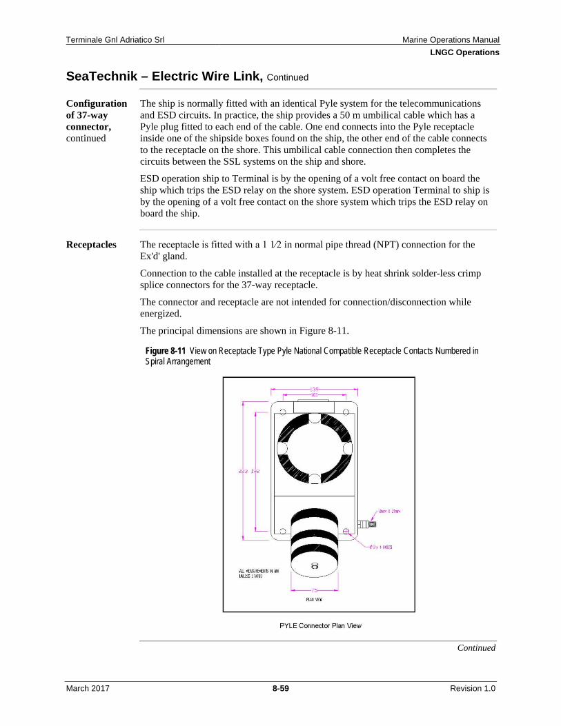
Figure 8-11 View on Receptacle Type Pyle National Compatible Receptacle Contacts Numbered in Spiral Arrangement ..................................................................... 8-59
Figure 10-1 LNGC Vetting and Approval Process ................................................... 10-4
Table 2-1 Vessel Types and Descriptions ................................................................... 2-2
Table 2-2 Onshore and Offshore Responsibilities ...................................................... 2-5
Table 3-1 Vessel Operator Review and Inspection Frequency Matrix ..................... 3-20
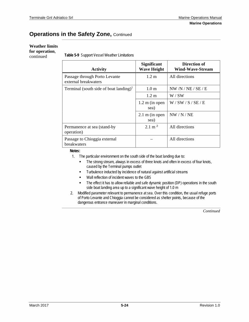
Table 5-9 Support Vessel Weather Limitations ........................................................ 5-24
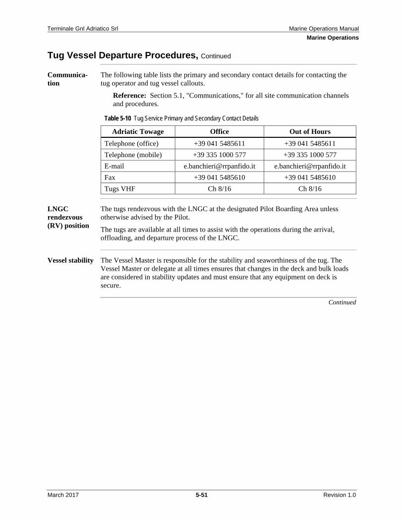
Table 5-10 Tug Service Primary and Secondary Contact Details ............................ 5-51
Table 5-11 FiFi Class Descriptions .......................................................................... 5-59
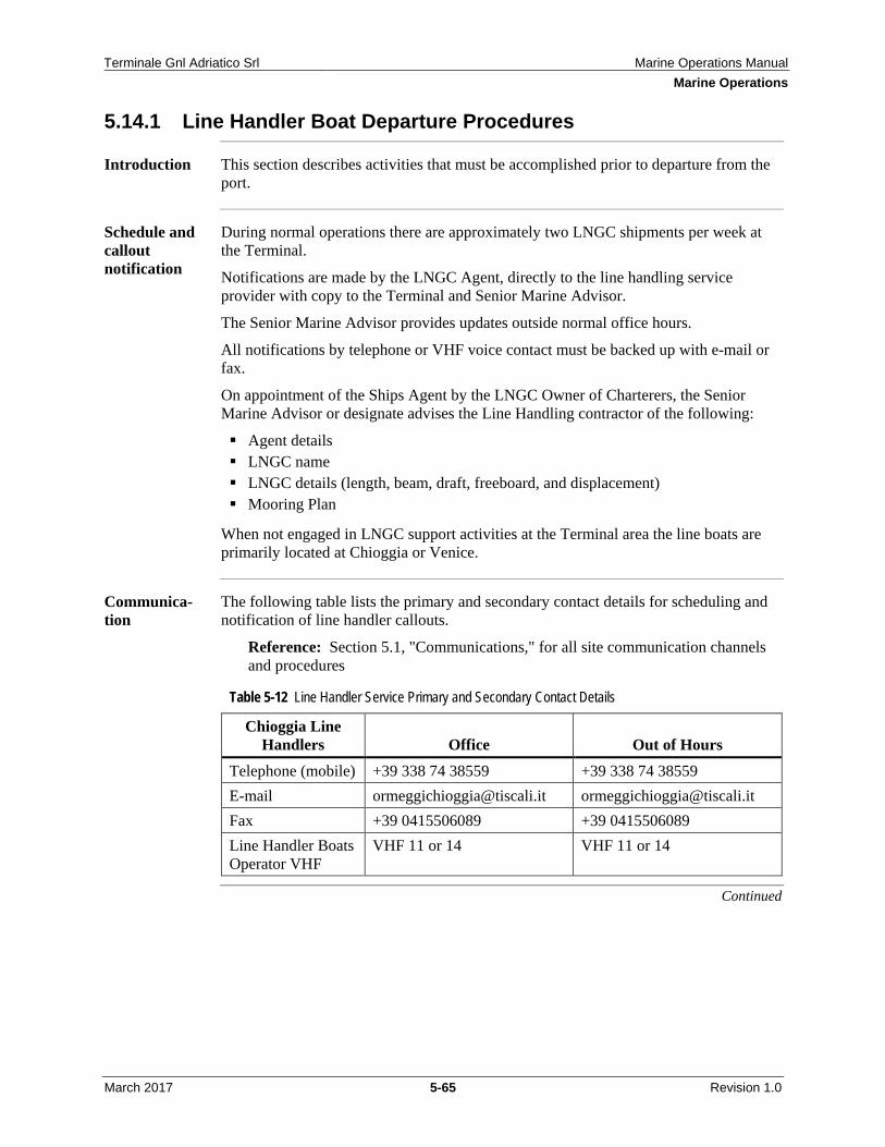
Table 5-12 Line Handler Service Primary and Secondary Contact Details .............. 5-65
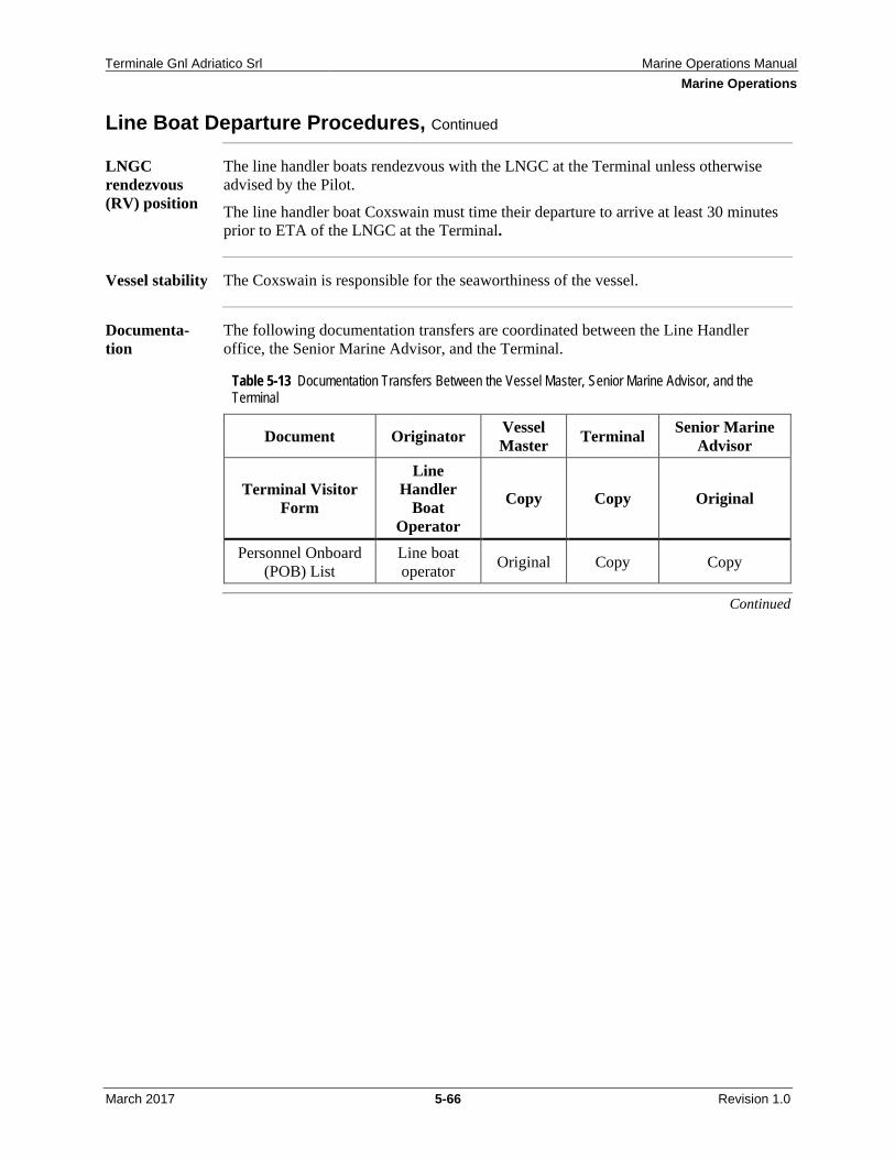
Table 5-13 Documentation Transfers Between the Vessel Master, Senior Marine Advisor, and the Terminal ................................................................................ 5-66
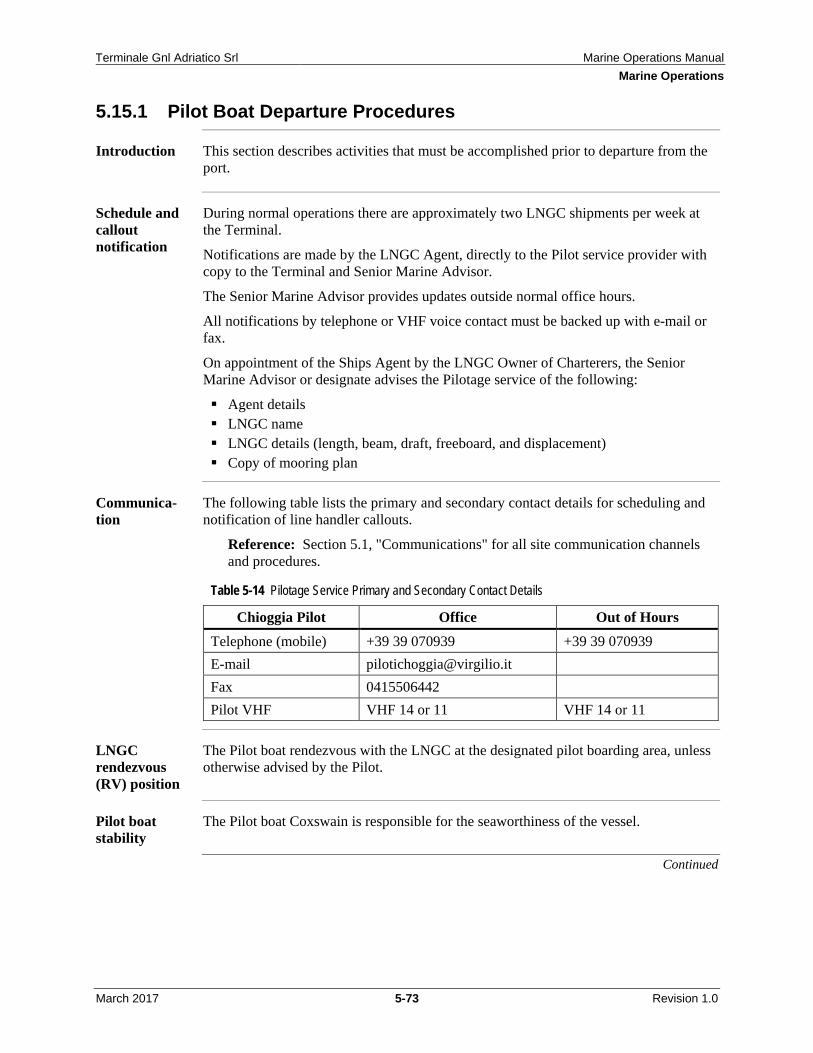
Table 5-14 Pilotage Service Primary and Secondary Contact Details ...................... 5-73
Table 7-1 Common Position Reference Systems ........................................................ 7-3
The Marine Operations Manual (MOM) provides a description about Terminale Gnl Adriatico Srl (ALNG) Marine Activities. These, as well as all other ALNG activities, are subject to the procedures and processes as described in ALNG's Safety, Security, Health and Environmental Management System (SHEMS). SHEMS principles should be observed in the MOM's implementation and stewardship.
The MOM is intended to assist ALNG's organizations in:
Pre-contract vessel and operator assessment. Daily operations involving planning, developing, and conducting the safe and
efficient marine activities of the ALNG chartered vessels. LNG unloading operations.
It covers chartered vessels supporting Offshore Operations, which include:
Tugs which provide assistance for a Liquefied Natural Gas Carrier (LNGC) berthing/unberthing and assistance during unloading operations
Crew supply vessels (CSV) Line handler vessels Pilot vessels Emergency response and rescue vessels (stand-by vessels) Diving vessels Remotely operated vehicle (ROV) and subsea intervention vessels
It also covers the activities involved with the operations to receive and unload LNGCs as well as the processes involved in vetting and accepting LNGCs.
While specific or specialized project marine operations vessels (such as, heavy lift, installation, pipe lay, and well work vessels) are not specifically covered, many of the general safety and operational guidelines noted for support vessels apply. Typically, these vessels are managed through external project companies, on a temporary basis, and related procedures and guidelines for these are dealt with on a case-by-case basis.
Notes: When "vessel(s)" is used throughout this manual, it typically refers to those marine vessels on
charter to, or under the control of, ALNG. Vessel does not refer to the LNGC. Though an industry standard for an onshore facility, the term "shore" is used in this document
only when it is part of the proper name of a system or equipment. As such, the terms "shore" and "Terminal" are used interchangeably (for example, "Ship/Shore Safety Checklist" is the "Ship/Terminal Safety Checklist").
Senior Marine Advisor Shore Base Manager Logistics Supervisor Logistics Staff Operations Installation Manager Operations Support Technician Terminal Jetty Operator Operations Advisor Vessel Masters Other users who interface with onshore and offshore marine activities
Specific Chapters relating to LNGC vetting and LNG unloading operations are used by the positions listed above as well as the following:
LNGC Masters Loading Masters Pilots
Guidelines for use
This document is intended to provide guidance. If any doubt exists regarding the document's contents, consult the ALNG Senior Marine Advisor.
Nothing in this document or in any recommendation issued by ALNG should be construed as relieving the vessel's Master, any officer, or crew member of their responsibility to exercise sound judgment as defined by Italian law, International law (applicable interfaces with a foreign vessel), Governmental regulation, Chioggia Coast Guard Ordinances, or to practice prudent seamanship and navigation. Additionally, this document does not supersede or prevent adoption of any local special requirements.
Marine vessel operation guidelines for use
The guidance herein should not be construed as authority to operate Marine Vessels in other than strict compliance with the regulatory requirements under which the vessel is registered and its area of operation.
This document does not supersede any requirements of the appropriate authorities for the area of operation, nor those of the Vessel Owner and Operator. This document may be distributed to vessel owners and operators and to third-party organizations as warranted by business needs. ALNG reserves the right to refer to this document as a set of expectations for contract execution and to use the document as a means to assess a provider's contract performance.
This manual is organized so that information can be found easily.
Tabbed dividers are organized by chapter. The Table of Contents in the front of the manual lists chapter titles, sections, and
major topics of each chapter. Each chapter includes a table of contents that lists the sections and topics within
that chapter. In each topic, the information is clearly labeled with margin headings that appear
in the left margin of each page.
To find specific information, locate the pertinent chapter and topic, and then scan the headings down the left margin of the page(s).
Action highlights
In this manual, WARNING, CAUTION, IMPORTANT, and Note are presented throughout the text and used to highlight various actions, as follows:
Warnings indicate situations in which bodily injury or death could occur through negligence or failure to follow the proper procedure. Example: ! WARNING: Under normal operation, all operating machinery and
electrical equipment must have safety guards, switches, and alarms in place and functional. Follow the proper operating procedures.
Cautions are used to inform users of undesirable consequences of actions or non-actions. Cautions are not as serious as warnings. Example: ▲ CAUTION: Do not attempt to stop a closing elevator door with your
hands or feet. Important information is more critical for the user than a note, but it does not
pertain to actions that can result in serious consequences. Example: ! IMPORTANT: Welding, burning, or hot work on painted surfaces or
stainless steel (or other alloys) should be evaluated for appropriate exposure control methods.
Notes express incidental information that is helpful in addition to the regular text information. Example: Note: Always plan an escape route in case of emergencies.
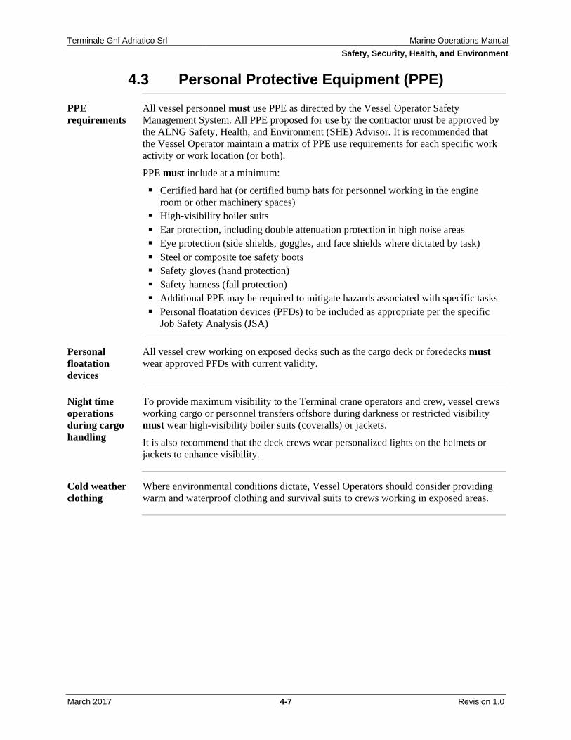
Introduction Vessels at a minimum, must meet all ALNG requirements regardless of Flag or local/international requirements.
It is recommended that the Code of Safe Working Practices for Merchant Seamen issued by the United Kingdom Maritime and Coastguard Agency be used as a reference as it provides detailed safety working practices onboard vessels including vessels servicing offshore oil and gas installations.
It is recommended that all vessels, irrespective of Flag, carry copies.
Det Norske Veritas (DNV) Marine Operations (MAROPS) Rules, Rules for Planning and Executing Marine Operations
International Organization for Standardization (ISO) 19901-6 – Marine Operations
International Maritime Organization (IMO), Offshore Supply Vessel (OSV) Code, 288E Code of Safe Practice for the Carriage of Cargoes and Persons by Offshore Supply Vessels
IMO 656E Implementation Guideline to MARPOL Annex V IMO 808E Code on Safety in Diving System IMO I620M Ballast Water Convention 2004 IMO 490 International Bunkers Convention IMO 646E Pollution Prevention Equipment IMO 946E Guide to Cold Water Survival IMO 116E International Code for the Security of Ships and Port Facilities (ISPS)
Code and International Convention for the Safety of Life at Sea (SOLAS) Amendment
IMO 117E International Safety Management (ISM) Code and Guidelines IMO T321E ISPS Port Facility Security Officer IMO 473E Civil Liability for Oil Pollution Damage IMO 904E Convention on International Regulations for Preventing Collisions at
Sea (COLREG) IMO 598E Guidelines for Ensura Adequacy Port Waste Reception Facilities IMO 282E International Convention of Safe Containers (CSC) IMO 120E Fire Prevention and Fire Fighting IMO 125E General Operator's Certificate for Global Maritime Distress and
Safety System (GMDSS) IMO DC520E International Convention for the Prevention of Pollution from
Ships (MARPOL) IMO DB938M International Convention of Standards of Training, Certification
and Watchkeeping for Seafarers (STCW) IMO DF110E International Convention for the Safety of Life at Sea (SOLAS) IMO International Safety Guide for Oil Tankers and Terminal IMO International Maritime Dangerous Goods Code Vol1 IMO International Maritime Dangerous Goods Code Vol2 Society of International Gas Tanker and Terminal Operators (SIGTTO) Liquefied
Fire Hazard Management SIGTTO Liquefied Gases-Marine Transportation and Storage
SIGTTO Recommendations for Manifolds Refrigerated Liquefied Natural Gas Carriers
SIGTTO Dedicated Clean Ballast Tank SIGTTO A Guide to Contingency Planning for Marine Terminals Handling
Liquefied Gas SIGTTO Safety in Liquefied Gas Tankers SIGTTO Liquefied Petroleum Gas Tanker Practice SIGTTO LNG Shipping Competency SIGTTO LNG Operations in Port Areas SIGTTO Ship to Ship Transfer Guide (Liquefied Gases) SIGTTO Human Error and the Environment Management System of the Gas Istituto Idrografico della Marina Militare Italiana (IIMM) II3133-08 Tavole di
Marea 2008 IIMM IMR007 Adriatic Pilot Oil Companies International Marine Forum (OCIMF) Ship Vetting and Its
Application to LNG OCIMF Effective Mooring OCIMF International Safety Guide for Oil Tankers and Terminals
Introduction Requests for exceptions to the "must" or "should" requirements of this MOM should be submitted to the Senior Marine Advisor who consults with the Shore Base Manager accordingly on each request.
Exceptions and changes
Exceptions and proposed changes to this manual should be submitted to the Senior Marine Advisor and processed through the ALNG Management of Change (MOC) process.
Guide review The Senior Marine Advisor is responsible for conducting an annual review of the Marine Operations Manual (MOM) to confirm the latest Regulatory requirements or industry practices or guidelines apply.
Note: Reviews and updates are administered by the Manual Owner, the ALNG Operations Manager.
Reference: Revision History
Terminale Gnl Adriatico Srl Marine Operations Manual General Information
March 2017 2-1 Revision 1.0
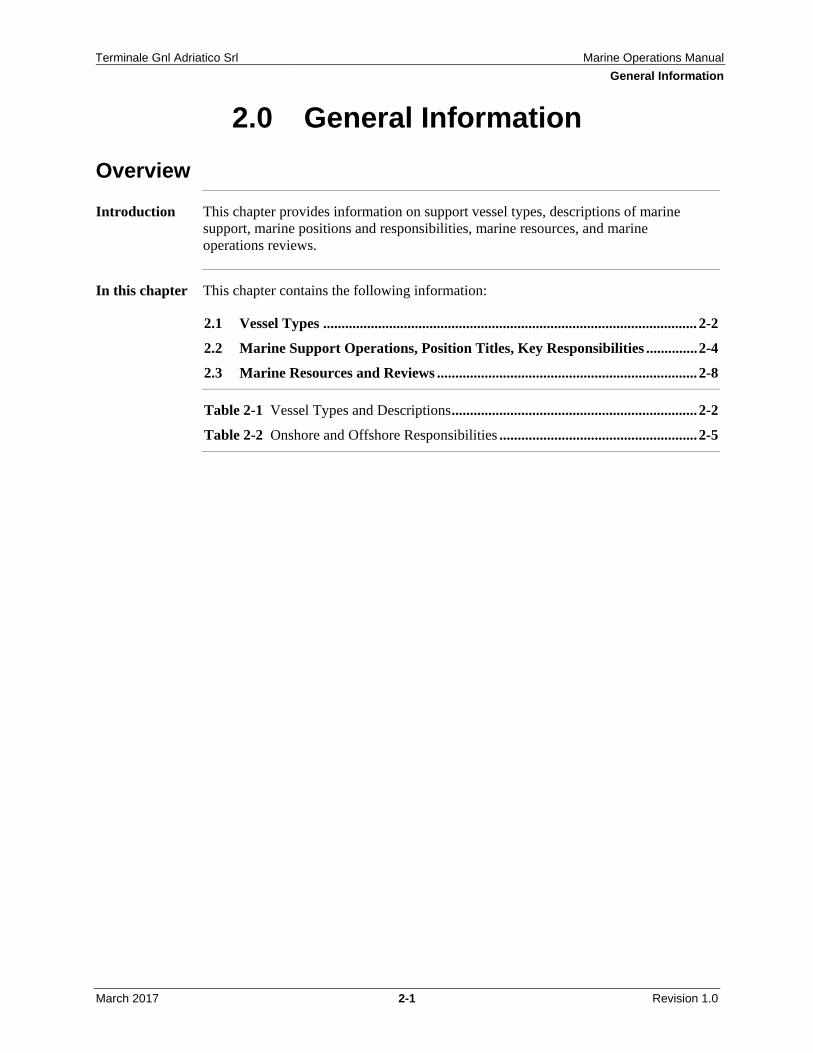
2.0 General Information Overview
Introduction This chapter provides information on support vessel types, descriptions of marine support, marine positions and responsibilities, marine resources, and marine operations reviews.
In this chapter This chapter contains the following information:
2.2 Marine Support Operations, Position Titles, Key Responsibilities .............. 2-4
2.3 Marine Resources and Reviews ....................................................................... 2-8
Table 2-1 Vessel Types and Descriptions ................................................................... 2-2
Table 2-2 Onshore and Offshore Responsibilities ...................................................... 2-5
Terminale Gnl Adriatico Srl Marine Operations Manual General Information
March 2017 2-2 Revision 1.0
2.1 Vessel Types
Vessel types The types of support vessels and abbreviations used below may vary around the world.
Table 2-1 Vessel Types and Descriptions
Vessel Type Description Crew Supply Vessel (CSV)
Note: The ALNG Marine & Marine & Logistic Supervisors responsible for the daily administration of the CSV.
Vessel used primarily for: Personnel transfer and transport between the Terminal and
Shore Base Supply (liquid and bulk) of goods and materials, generally
in containers
Optional capabilities: Oil spill response Field standby and man overboard rescue Search and rescue Any combination of these
! IMPORTANT: Any available vessel, depending on circumstances, may be used for man overboard rescue or to provide assistance in other emergency situations.
Tug Boats Vessel used primarily for: Offshore mooring/unmooring operations and providing
assistance during unloading operations
Optional capabilities: Field standby and man overboard rescue Fire fighting Additional maintenance or other Terminal requested
works, such as fender positioning as specifically noted in the ALNG/Contractor Agreement
Fast Rescue Boat Vessel used primarily for offshore emergency response and rescue; located on board the Terminal and manned by offshore personnel.
Line Handlers Vessel (LHV)
Vessel used for handling lines and mooring ropes during liquefied natural gas (LNG) Carrier (LNGC) mooring operations.
Pilot Boat Vessel used to transport Pilot and Loading Master to the LNGC.
High Speed Craft Vessel used to transport technical and other support personnel to the Terminal and LNGC as requested by the Senior Marine Advisor.
Continued
Terminale Gnl Adriatico Srl Marine Operations Manual General Information
March 2017 2-3 Revision 1.0
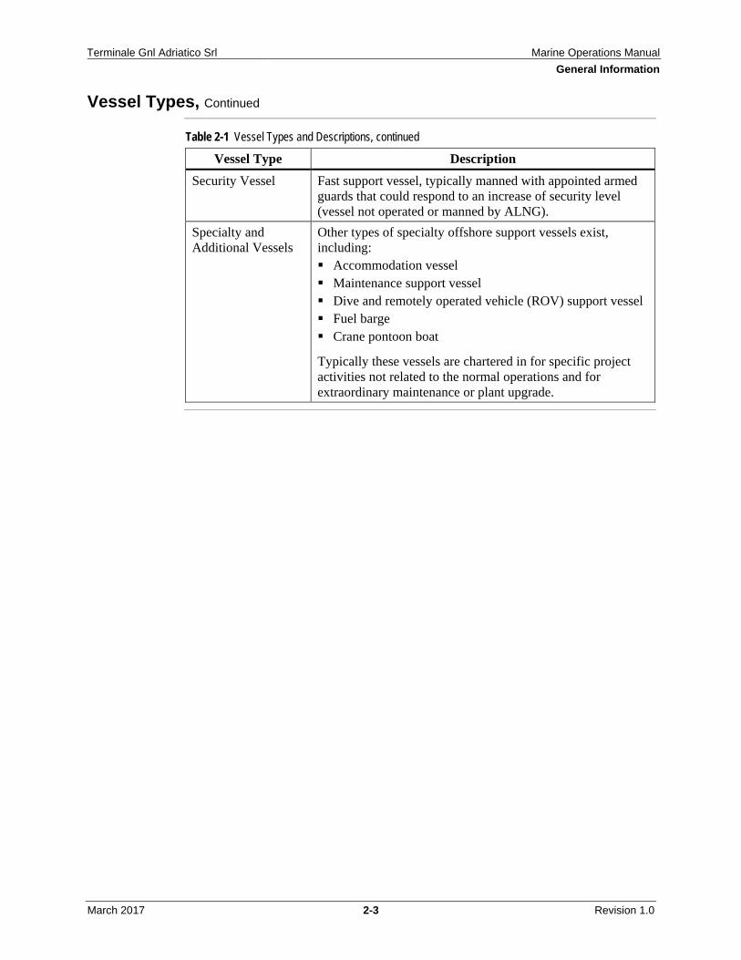
Vessel Types, Continued
Table 2-1 Vessel Types and Descriptions, continued
Vessel Type Description Security Vessel Fast support vessel, typically manned with appointed armed
guards that could respond to an increase of security level (vessel not operated or manned by ALNG).
Specialty and Additional Vessels
Other types of specialty offshore support vessels exist, including: Accommodation vessel Maintenance support vessel Dive and remotely operated vehicle (ROV) support vessel Fuel barge Crane pontoon boat
Typically these vessels are chartered in for specific project activities not related to the normal operations and for extraordinary maintenance or plant upgrade.
Terminale Gnl Adriatico Srl Marine Operations Manual General Information
March 2017 2-4 Revision 1.0
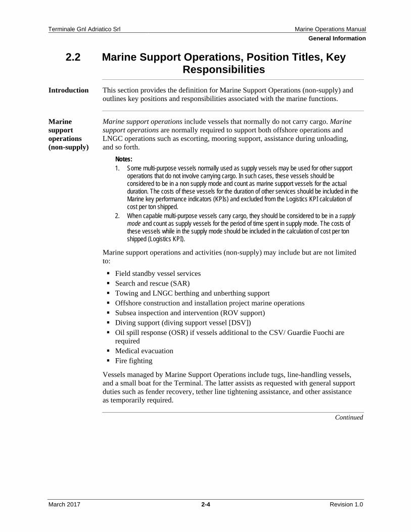
2.2 Marine Support Operations, Position Titles, Key Responsibilities
Introduction This section provides the definition for Marine Support Operations (non-supply) and outlines key positions and responsibilities associated with the marine functions.
Marine support operations (non-supply)
Marine support operations include vessels that normally do not carry cargo. Marine support operations are normally required to support both offshore operations and LNGC operations such as escorting, mooring support, assistance during unloading, and so forth.
Notes: 1. Some multi-purpose vessels normally used as supply vessels may be used for other support
operations that do not involve carrying cargo. In such cases, these vessels should be considered to be in a non supply mode and count as marine support vessels for the actual duration. The costs of these vessels for the duration of other services should be included in the Marine key performance indicators (KPIs) and excluded from the Logistics KPI calculation of cost per ton shipped.
2. When capable multi-purpose vessels carry cargo, they should be considered to be in a supply mode and count as supply vessels for the period of time spent in supply mode. The costs of these vessels while in the supply mode should be included in the calculation of cost per ton shipped (Logistics KPI).
Marine support operations and activities (non-supply) may include but are not limited to:
Field standby vessel services Search and rescue (SAR) Towing and LNGC berthing and unberthing support Offshore construction and installation project marine operations Subsea inspection and intervention (ROV support) Diving support (diving support vessel [DSV]) Oil spill response (OSR) if vessels additional to the CSV/ Guardie Fuochi are
required Medical evacuation Fire fighting
Vessels managed by Marine Support Operations include tugs, line-handling vessels, and a small boat for the Terminal. The latter assists as requested with general support duties such as fender recovery, tether line tightening assistance, and other assistance as temporarily required.
Continued
Terminale Gnl Adriatico Srl Marine Operations Manual General Information
March 2017 2-5 Revision 1.0
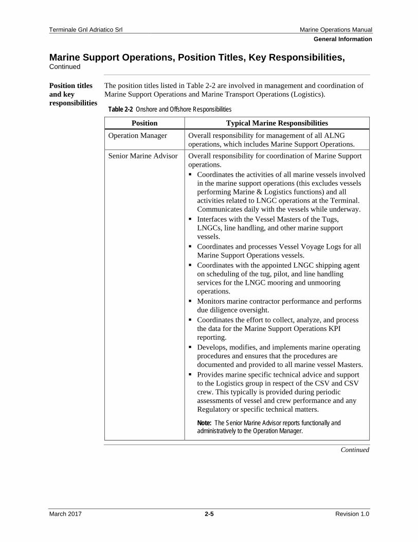
Marine Support Operations, Position Titles, Key Responsibilities, Continued
Position titles and key responsibilities
The position titles listed in Table 2-2 are involved in management and coordination of Marine Support Operations and Marine Transport Operations (Logistics).
Table 2-2 Onshore and Offshore Responsibilities
Position Typical Marine Responsibilities Operation Manager Overall responsibility for management of all ALNG
operations, which includes Marine Support Operations. Senior Marine Advisor Overall responsibility for coordination of Marine Support
operations. Coordinates the activities of all marine vessels involved
in the marine support operations (this excludes vessels performing Marine & Logistics functions) and all activities related to LNGC operations at the Terminal. Communicates daily with the vessels while underway.
Interfaces with the Vessel Masters of the Tugs, LNGCs, line handling, and other marine support vessels.
Coordinates and processes Vessel Voyage Logs for all Marine Support Operations vessels.
Coordinates with the appointed LNGC shipping agent on scheduling of the tug, pilot, and line handling services for the LNGC mooring and unmooring operations.
Monitors marine contractor performance and performs due diligence oversight.
Coordinates the effort to collect, analyze, and process the data for the Marine Support Operations KPI reporting.
Develops, modifies, and implements marine operating procedures and ensures that the procedures are documented and provided to all marine vessel Masters.
Provides marine specific technical advice and support to the Logistics group in respect of the CSV and CSV crew. This typically is provided during periodic assessments of vessel and crew performance and any Regulatory or specific technical matters.
Note: The Senior Marine Advisor reports functionally and administratively to the Operation Manager.
Continued
Terminale Gnl Adriatico Srl Marine Operations Manual General Information
March 2017 2-6 Revision 1.0
Marine Support Operations, Position Titles, Key Responsibilities, Continued
Table 2-2 Onshore and Offshore Responsibilities, continued
Position Typical Marine Responsibilities Logistics Supervisor Overall responsibility for coordination of Marine
Transport (Logistics) services. Coordinates the day-to-day scheduling of the CSV
operational runs. Coordinates loading and offloading of the CSV at the
Shore Base. Coordinates the personnel boarding and disembarkation
from the CSV. Interfaces with the CSV Master. Coordinates and processes Vessel Voyage Logs for the
CSV. Monitors marine contractor performance for the CSV. Coordinates the effort to collect, analyze, and process
the data for the Marine Transport (Logistics) KPI reporting.
The Marine & Logistic Supervisor reports functionally and administratively to the Shore Base Manager.
Note: The Senior Marine Advisor provides marine specific technical advice and support to the Logistics group in respect of the CSV and CSV crew. This typically is provided during periodic assessments of marine vessels and crew performance and any Regulatory or specific technical matters.
Logistics Coordinator Supervises Shore Base assistants and all quayside activities, and reports to the Logistics Supervisor.
Offshore Installation Manager (OIM)
Overall responsibility for the Terminal and all marine traffic in the field.
Operations Support Technician
Administers and supervises daily marine traffic tasks in the field.
Communicates with the CSV. Prepares shipping documentation and manifests. Assists in cargo transfer operations. Reports to the OIM.
Continued
Terminale Gnl Adriatico Srl Marine Operations Manual General Information
March 2017 2-7 Revision 1.0
Marine Support Operations, Position Titles, Key Responsibilities, Continued
Table 2-2 Onshore and Offshore Responsibilities, continued
Position Typical Marine Responsibilities Crane Operator Oversees crane operations, cargo transfers between
vessels, and maintains communication with the Vessel Master and deck crew.
Supervises the deck crew as appropriate. Vessel Master Responsible for safety and efficiency of crew and vessel. Loading Master Oversees the offloading operations of LNGCs on behalf of
ALNG. Pilot Acts as advisor to the LNGC Master in all LNGC berthing
and unberthing operations. Responsible for communicating and directing tugs and line handling vessels during LNGC berthing and unberthing operations.
! IMPORTANT: The OIM (or deputy) or the Vessel Master may delay the start or continuation of vessel operation if either considers it unsafe to proceed.
Training Training is specified by ALNG for various Marine Vessel Masters and crew, Loading Masters, Pilots, and other positions. These requirements are typically detailed in the respective Agreement(s) for the specific services provided, and the applicable Agreements should be consulted to identify these training requirements.
All personnel are required to complete Basic Offshore Safety Induction and Emergency Training (BOSIET) training as per the respective Agreements. As Loading Masters and line handlers are subject to stays on the Terminal, they must also complete the ALNG Company Internal Safety Training (CIST) course.
These training, qualifications, and experience requirements are normally the responsibility of the Contractor to provide and to ensure its personnel are trained, competent, and certified accordingly as described in the Agreement(s).
Pilots must meet all training requirements stipulated by Italian legislation.
In addition to training and qualifications stated in the respective Agreements, ALNG currently requires Pilots, Loading Masters, and Tug Boat Masters to successfully complete the Force Technology (Danimark) Marine Pilot Course.
Terminale Gnl Adriatico Srl Marine Operations Manual General Information
March 2017 2-8 Revision 1.0
2.3 Marine Resources and Reviews
External and additional resources
Dependent on the chartered support vessel fleet, ALNG Operations Management may include one or more marine-related positions with responsibility for the day-to-day oversight of the Onshore Marine Department managing marine support operations.
The key responsibilities include:
Day-to-day scheduling and coordinating of supply, support, and crew vessels Coordinating loading and offloading of vessels at the shore base Interfacing with vessel Masters and Operators Coordinating and processing voyage logs Monitoring vessel fuel consumption Monitoring vessel(s) performance
Qualified Marine Advisors
Assistance to ALNG in matters concerning Marine support vessel requirements and this Marine Operations Manual (MOM) can be provided by other stakeholder or industry Marine Advisors.
Marine operations reviews
Initial and periodic technical or operational "cold eyes" reviews or assessments of the ALNG Marine support vessel operations should be conducted by the ALNG Senior Marine Advisor reporting to ALNG Operations management.
Reference: Chapter 3.0, "Vessel Selection and Contracting," for Vessel Operator assessments and Vessel Inspections.
Startup or other operations with a high level of activity may require reviews that are more frequent.
Pre-mobilization or pre-start up operational risk assessments may also be required.
Introduction This chapter provides detail on spot support vessel selection and contracting, including pre-qualification, technical evaluation, vessel inspections, and contractor interface.
ALNG's core vessels, which provide longer-term services on an ongoing charter basis, are the crew supply vessel (CSV), tugs, and line handler boats. All other marine vessels are considered spot charter vessels that fulfill a temporary operational need.
Note: Marine Vessel Charter Services Agreements are used for core vessels. The Charter Party outlines the legal part of the agreement. ALNG develops the specific Scope of Work describing the level of support for ongoing operations and the coordination procedures that regulate the interfaces between the Charterer and the Contractor.
Contractor selection and management
When engaged in vessel selection, contracting, and on-going vessel contractor interface, the ALNG Procurement Department is consulted and involved in the process in accordance with the Safety, Security, Health, and Environmental Management Systems (SHEMS) Manual System 8A, Contractor Selection and Management System, document.
This chapter of the Marine Operations Manual provides specific guidelines on marine vessel selection, contracting, and on-going interface with ALNG Procurement.
Reference: SHEMS System 8A document, Contractor Selection and Management System
In this chapter This chapter contains the following information:
Figure 3-1 Links Between Contractor Selection and Management Focus Areas and OCIMF Elements .............................................................................................. 3-12
Table 3-1 Vessel Operator Review and Inspection Frequency Matrix ..................... 3-20
The ALNG Operations Leadership Team (OLT) reviews proposals submitted internally within the group, or by other groups within ALNG, related to future marine vessel needs and initiates appropriate action as required for developing any long term Marine contract plans.
When an extraordinary service requirement occurs, the user group or requestor must identify the need by contacting the Senior Marine Advisor and describing the requirements.
The Senior Marine Advisor evaluates the most cost-effective way to provide the requested service.
Alternatives may be:
Revise current vessel(s) schedule. Utilize sharing or leveraging. Spot charter required capacity and capability.
The Senior Marine Advisor is responsible for:
Developing the marine contract work scope and coordination procedures. Marine vessel contract administration. Performing on-hire surveys and periodic marine safety inspections and vessel
crew revalidations.
Contractor interfacing
It is important that during the requisition stage the amount, type, and level of interfacing with the contractor is determined.
With the often high consequence levels associated with Marine vessel operations, Marine support vessel contracts are considered a potentially higher Safety, Security, Health, and Environmental Management Systems (SHEMS) impact service with more frequent or higher exposure hour services.
ALNG Procurement is wholly responsible and accountable for the Bidding Process and Procedures as per SHEMS System 8A.
When tendering for long term support vessel(s) services a Procurement Plan is developed by the Procurement group with input and support from the Terminal and Shore Base organizations. This plan should include a process for Bidder Quality Assurance as required under SHEMS System 8A.
This Plan includes:
Contract Schedule Detailed Scope of Work, including vessel minimum specification and
performance requirements as provided by the Senior Marine Advisor SHEMS requirements Contractor SHEMS qualifying criteria as noted in SHEMS 8A, Contractor
Selection and Management System, "Overview," and other relevant sections An onsite visit and inspection of the Senior Marine Advisor
Reference: SHEMS 8A document, Contractor Selection and Management System
Scope of work Details of the work scope should include:
Area of Operations and Operating Ports Primary activities to be performed by the vessel (for example, supply, stand-by,
towing, and so forth) Secondary activities to be performed by the vessel (for example, firefighting, oil
spill response, and so forth) Any specific work activity requirements, including bridge manning requirements
in the safety zone, that may require an increased manning level Reference: Section 4.2, "Crew Manning and Training," "Minimum crew requirements"
Any requirements for operator management presence in country or region Any specific crew training or certification requirements (such as, oil spill response
[OSR], rigger, personnel transfer, and so forth) Requirement to comply to all applicable Italian laws Weather and environmental limiting conditions
Development of minimum vessel specification and performance requirements
Selection of spot vessel(s) depends on the nature, type, and scope of operations for which the vessel(s) are being hired and are usually characterized by the purpose for which they are used, such as:
Crew supply vessels Tug boat and line handler boat Diving support vessel Standby and rescue vessel Utility vessel, such as Fender assistance boat and so forth
Minimum specifications and performance should be developed in the work scope, based on local regulatory and safety compliance and general industry experience with vessels operating under the local conditions, including met-ocean conditions (fog, sea state, wind speed, and so forth), and may include:
Any length or breadth limits Vessel draft limits (shore base, channel, or other water depth considerations) Applicable vessel class notation requirements:
– Firefighting (FiFi) – Dynamic position (DP) class Reference: Chapter 7.0, "Specialized Vessel Operations"
– Hull and machinery notation – Tug notation – Environmental aspects related to clean and human factors such as comfort or
habitability (or both) – Accommodation vessel notation Note: Classification societies that are members of the International Association of Classification Societies are recommended.
Any country or flag requirements Minimum speed Bollard pull/horsepower Dynamic position (DP) station keeping capability (sea height, wind speed, wave
period, current) Standby and rescue services (survivor capability) Accommodation and seating capacity Deck space and tonnage capacity, including any cargo deck length requirements Bulk under deck capabilities and capacities Bulk hose transfer arrangements and pumping capabilities Fuel transfer meter requirements Passenger transfer capabilities (swing rope, "V" notch, and so forth)
Development of minimum vessel specification and performance requirements, continued
Oil Spill response capabilities (skimmers, booms, recovery tank capacity, and so forth)
Crane safe working load (SWL) and reach Towage capabilities Fender requirements Any emission, fuel consumption capacity, duration, fuel type, and propulsion
requirements Communication requirements (radio transmission, email, fax, and so forth) Other special equipment or design requirements for the intended work or
environment
These minimum specifications together with scope of work are included as part of the Tender package.
End client requirements
When developing the vessel minimum specification requirements it is important that the end clients (Operations, Technical, and so forth) are closely consulted and are aligned.
SHEMS requirements
The ALNG Corporate Procurement Manual includes guidelines and SHEMS requirements related to the procurement and chartering process.
Appropriate SHEMS manuals or documents, to which the contractor must comply, should be included or referenced, as appropriate, in the Tender package. Any specific SHEMS requirements, relative to the scope of work or function of the vessel(s) should be included in the Tender package.
Introduction This section contains the following information:
Identifying potential bidders Vessel operator pre-qualification process, which includes ALNG on site visit(s) Safety performance Use of Oil Companies International Marine Forum (OCIMF) Offshore Vessel
Management Self-Assessment (OVMSA) Note: OCIMF OVMSA processes may be used as a guide and are referenced accordingly in this manual. ALNG typically uses comprehensive Marine Safety Checklists, such as the Marine Inspection for Small Workboats questionnaire, to evaluate vessel and operator qualifications as part of the pre-award process and during operations. These checklists may also be used for ongoing evaluation of marine vessels to determine their continued suitability.
Reference: Section 3.9, "Tools," for the Marine Inspection for Small Workboats
One of the first steps in the vessel tendering process is to identify potential suitable bidders to be invited to the Vessel Tender process. This identification of potential bidders is completed by ALNG.
When developing this list the following should be considered:
Type of vessel(s) and services for which the vessel(s) is being tendered Experience and safety record of existing providers supplying similar services in
the region Local, Government, and Procurement requirements and Stakeholder input Other Local Ownership, Cabotage Law, or Bidder qualification requirements Confirmed interest of potential bidder to be invited to the Tender Known abilities of vessel(s) operator to support local operations Appropriate available equipment
On agreement of the potential list of bidders, each of the bidders must be pre-qualified to confirm their suitability to perform satisfactorily when compared with contract requirements and ALNG operating standards.
It is important to assess through a pre-qualification assessment or evaluation process each potential bidder's SHEMS performance and Safety Management Systems and the elements it contains as well as its effective implementation, measurement, and any gaps.
The Contractor may be considered SHEMS qualified in three ways:
Documented proof that the Contractor performs or performed the same or similar service for ALNG within the last three years with an acceptable SHEMS performance, with evidence of prior satisfactory safety audits or pre-qualification.
Third-party SHEMS type auditors accepted by ALNG perform a professional audit and qualify contractor according to SHEMS standards.
Contractor goes through an ALNG accepted pre-qualification process.
Pre-qualification questionnaire
A pre-qualification questionnaire can be developed to evaluate potential contractors. These are typically based on five general key focus areas of contractor SHEMS performance:
Leadership and communication Crew competency Worker empowerment and involvement Program effectiveness Gap closure
The pre-qualification or the Contractor Evaluation Questionnaire can be expanded to cover the specific issues associated with Offshore support vessel operations.
Overview Vessel operator key performance indicators (KPIs) for at least the last three years should be requested and evaluated against the agreed minimum target level set by ALNG. This includes:
Lost time incident (LTI) and associated rate Restricted work incident (RWI) Medical treatment incident (MTI) First aid (FA) incident Near loss investigation (NLI) Total recordable incident (TRI) rate Number of safety meetings Number of Management walk-throughs Number of Port State detentions, insurance claims, and so forth Number of collision, grounding, and oil spill incidents
Note: LTI rates or TRI rates should be reported in line with Occupational Safety and Health Administration (OSHA) requirements and based on 200,000 exposure man hours.
Overview ALNG typically uses a comprehensive Marine Safety Checklist to evaluate vessel and operator qualifications as part of the pre-award process and during operations.
The OCIMF OVMSA program may be utilized during the pre-qualification stage to evaluate potential bidder qualification.
Elements contained within OVMSA
The Elements contained within the OVMSA document are:
Management, leadership, and accountability Recruitment and management of shore based personnel Recruitment and management of vessel personnel Reliability and maintenance standards Navigational safety Offshore operations and the management of contractors Management of change Incident investigation and analysis Safety management Environmental management (including fuel management)
Reference: Chapter 5.0, "Marine Operations" Emergency preparedness and contingency planning Measurement, analysis and improvement
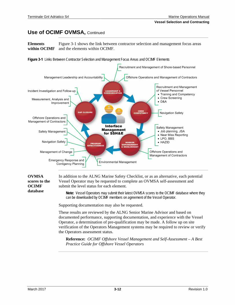
Figure 3-1 shows the link between contractor selection and management focus areas and the elements within OCIMF.
Figure 3-1 Links Between Contractor Selection and Management Focus Areas and OCIMF Elements
OVMSA scores to the OCIMF database
In addition to the ALNG Marine Safety Checklist, or as an alternative, each potential Vessel Operator may be requested to complete an OVMSA self-assessment and submit the level status for each element.
Note: Vessel Operators may submit their latest OVMSA scores to the OCIMF database where they can be downloaded by OCIMF members on agreement of the Vessel Operator.
Supporting documentation may also be requested.
These results are reviewed by the ALNG Senior Marine Advisor and based on documented performance, supporting documentation, and experience with the Vessel Operator, a determination of pre-qualification may be made. A follow up on site verification of the Operators Management systems may be required to review or verify the Operators assessment status.
Reference: OCIMF Offshore Vessel Management and Self-Assessment – A Best Practice Guide for Offshore Vessel Operators
ALNG sets the qualification criteria, including safety performance criteria.
Vessel Operators that meet the minimum scoring criteria as set by ALNG are considered pre-qualified and added to the final bidder list.
When developing minimum criteria, the following types of items are considered:
Vessel Operator LTI, NLI, and TRI rates and trends Number of fatalities Number of collision, grounding, and oil spill incidents OVMSA levels for each of the elements (levels are rated from 0 to 4), if an
OVMSA is completed Contractor SHEMS qualifying criteria as noted in SHEMS 8A, Contractor
Selection and Management System, "Overview," and other relevant sections
Reference: SHEMS 8A document, Contractor Selection and Management System
Gap closure Gaps identified during the pre-qualification and decision to qualify or not must be documented.
Any gaps identified during the pre-qualification process are communicated back to the qualified bidders so they can take immediate action and include a Gap Closure Plan in the bid package.
Reference: Section 3.3, "Technical Bid Package"
Where local regulations or contract practices may preclude the qualification and selection of the contractor, the prequalification process and use of the OVMSA, or similar process, provides a valuable opportunity to complete a gap assessment in order to develop and execute a gap closure plan and to modify final contract terms accordingly.
SHEMS and interface management exhibit Vessel(s) type and minimum specification or performance requirements Scope of work Proposal forms to be used by bidders
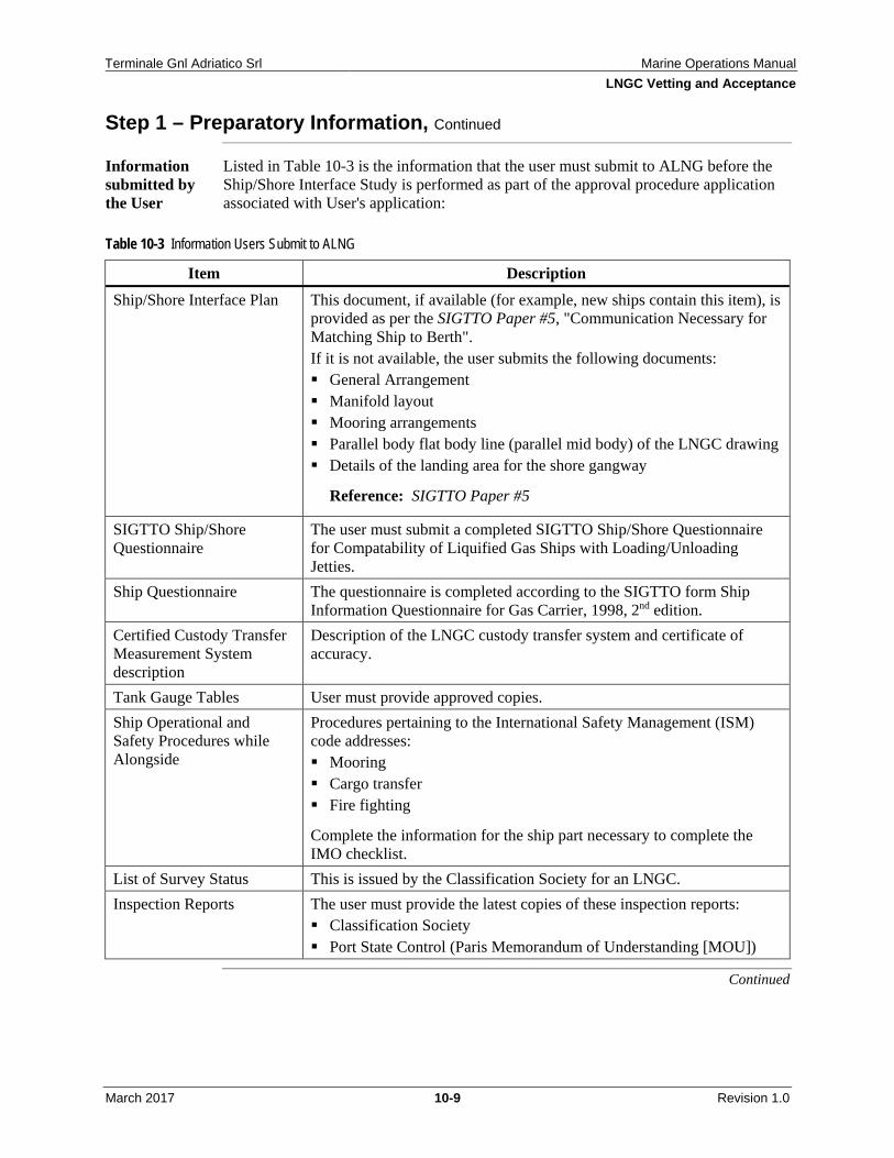
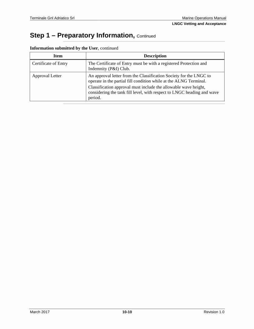
Reference: Chapter 10.0, "LNGC Vetting and Acceptance," could be requirements for LNGCs
A technical evaluation plan is developed and includes the specific items the bidder is required to provide in the proposal and set evaluation criteria, including minimum specification or performance requirements.
On receipt of technical bids, ALNG may assemble a team of appropriate subject matter experts (SMEs) including the Senior Marine Advisor to evaluate the technical responses from each of the bidders.
International Marine Transportation Ltd. (IMT) may be used to vet the vessels as part of the screening process.
The bid responses are weighed against set criteria as defined in the technical evaluation plan and collective decision is made on technical acceptability of the bidders response and offered vessel(s).
Minimum specification requirements
The offered vessels technical acceptance is weighed against the minimum specification or performance requirements with any pass/fail criteria being first identified.
Vessels that fail to meet the identified minimum requirements should be removed from the bid list.
Contractor Execution Plan
Evaluation of the Contractor Execution Plan includes evaluation of the Vessel Operator's plan to address the identified gaps from the pre-qualification process.
Vessel inspections
Prior to final technical acceptance ALNG may require that the offered vessel(s) are inspected by a qualified inspector to confirm technical suitability, general condition, and onboard SHEMS management.
To avoid multiple vessel inspections ALNG may elect to only inspect the final vessels offered by the successful bidder, contract award being contingent on satisfactory vessel inspection.
Reference: Section 3.5, "Vessel Inspections"
Vessel inspection gap closure
Where required, any issues noted during the vessel inspection should be documented and communicated to the Vessel Operator and any specific terms agreed and written into the final contact.
Where the vessel has been inspected and found unacceptable for technical or SHEMS reasons, the procurement process must be followed.
MESQAC-OV In special circumstances, the Marine Environmental, Safety, and Quality Assurance Criteria for Offshore Vessels (MESQAC-OV) produced by an ALNG stakeholder, may be used by ALNG in the screening process. The MESQAC-OV uses a standard methodology to provide offshore vessel operators with an understanding of the marine environmental, safety, and quality assurance expectations of vessels under consideration for ALNG use to promote continuous improvement.
Vessels not meeting a must criterion as stated in the MESQAC-OV may still be considered for service subject to acceptable mitigation measures agreed to by ALNG, and put in place. Where meeting certain of these criteria requires long lead times (for example, dry docking the vessel), a limited waiver period may be granted by ALNG. This is upon receipt of written confirmation from the operator that corrective action will be taken at the earliest practical opportunity, and an agreed mitigating procedure is in place.
OVMSA gap closure and continuous improvement
OVMSA element level status (or a status set by ALNG) effective on the date of the Contract award may be agreed and written into the contract terms, together with minimum OVMSA level status (or a status set by ALNG) that should be maintained throughout the contract term.
Reference: ALNG Master Time Charter Agreement
The Vessel Operator is encouraged to periodically review and update the OVMSA status striving to maintain continuous improvement.
ALNG may perform periodic reviews of the Vessel Operator management systems to verify status level and continuous improvement.
Prior to final execution of a contract or during the technical evaluation stage of the bid process ALNG may perform, or require, an inspection of the offered vessels to confirm suitability. This inspection should be conducted by the Senior Marine Advisor or qualified third party inspector.
The inspection should cover the following main areas:
Certification and documentation Crew and Contractor management Navigation Safety and security management Risk management Pollution prevention and environmental management Structural condition Operations Mooring Communications Propulsion, power generation, and machinery General appearance and condition DP operations (if applicable) Specific work activity (tanker/mooring assistance, supply, and so forth)
Ad hoc or spot chartered vessels may be chartered from remote or inaccessible locations or while at sea without the possibility of inspecting the vessel prior to commencing the charter. In such cases, the Senior Marine Advisor evaluates the actual vessel's previous record of performance and requests that the Vessel Owner or Vessel Master (or both) confirm that the ship is seaworthy in all respects.
A checklist or declaration form, comprised of example items listed above, should be developed for completion by the Vessel Master when spot chartering without being able to physically inspect the vessel.
OCIMF inspection
Use of the OCIMF Offshore Vessel Inspection Questionnaire (OVIQ) and an OCIMF accredited inspector may be used for pre-contract execution inspections, as determined by ALNG. Alternatively, where an existing inspection report of the vessel is contained within the OCIMF Offshore Vessel Inspection Database (OVID), these reports can be used.
On arrival of the vessel at the ALNG specified site (place of delivery), an on-hire survey to confirm vessel readiness to conduct operations may be completed.
This inspection should include:
Review of certification and documentation General condition and appearance Safety and security Equipment condition and readiness
Usually at this time a survey of vessel tanks to confirm cleanliness is conducted and measurement of any remaining onboard consumables is conducted, including on hire survey of fuel.
Additionally, ALNG should provide the Vessel Master with copies of ALNG specific documents and review with the Master all reporting requirements including daily reporting logs, communications with offshore and shore base, emergency response, and incident notification procedures, as well as provide any ALNG safety orientation program that maybe in place.
DP trials Where a vessel is required to use DP for the varying activities the vessel is engaged in, ALNG requires a DP trial and survey by a qualified inspector or the Senior Marine Advisor prior to commencing DP operations in the field.
References: Chapter 7.0, "Specialized Vessel Operations" SHEMS System 8A, Contractor Selection and Management System
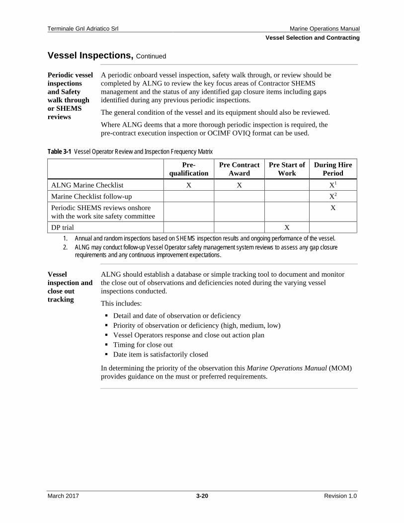
Periodic vessel inspections and Safety walk through or SHEMS reviews
A periodic onboard vessel inspection, safety walk through, or review should be completed by ALNG to review the key focus areas of Contractor SHEMS management and the status of any identified gap closure items including gaps identified during any previous periodic inspections.
The general condition of the vessel and its equipment should also be reviewed.
Where ALNG deems that a more thorough periodic inspection is required, the pre-contract execution inspection or OCIMF OVIQ format can be used.
Table 3-1 Vessel Operator Review and Inspection Frequency Matrix
Pre-
qualification Pre Contract
Award Pre Start of
Work During Hire
Period ALNG Marine Checklist X X X1 Marine Checklist follow-up X2 Periodic SHEMS reviews onshore with the work site safety committee
X
DP trial X 1. Annual and random inspections based on SHEMS inspection results and ongoing performance of the vessel. 2. ALNG may conduct follow-up Vessel Operator safety management system reviews to assess any gap closure
requirements and any continuous improvement expectations.
Vessel inspection and close out tracking
ALNG should establish a database or simple tracking tool to document and monitor the close out of observations and deficiencies noted during the varying vessel inspections conducted.
This includes:
Detail and date of observation or deficiency Priority of observation or deficiency (high, medium, low) Vessel Operators response and close out action plan Timing for close out Date item is satisfactorily closed
In determining the priority of the observation this Marine Operations Manual (MOM) provides guidance on the must or preferred requirements.
To the extent possible, short term or spot-hire vessels should be contracted with a Vessel Operator presently operating with ALNG or with which ALNG has recent documented acceptable SHEMS performance.
Where practical ALNG should arrange a pre-contract inspection or on-hire inspection (or both) to confirm vessel suitability prior to commencing work.
OCIMF inspection database
Where an existing inspection report of the vessel is contained within the OCIMF OVID these reports can be downloaded at a minimum cost for review prior to hire of vessel.
It is recommended that vessels or barges (including bunker barges) specifically hired for the carriage or storage of fuel and classified as an oil tanker or oil barge are vetted and approved for hire. Currently, this is performed using the vessel vetting process managed by International Maritime Transportation, Ltd. (IMT).
SHEMS Systems 5B and 8A provide guidelines on contractor interface requirements to steward contractor safety performance and support the contractor in achieving improved SHEMS performance by means of a systematic approach to identify the appropriate responsible persons for the contractor/owner and ALNG respectively. Interface activities should occur at three levels:
Level 1 – Daily interface activities during execution of work Level 2 – Regular Senior Marine Advisor and Contractor local lead face-to-face
ALNG requires regular stewardship of key performance indicators (KPIs). Descriptions and examples of ALNG KPIs are covered in Chapter 11.0, "Key Performance Indicators and Stewardship."
In addition to any ALNG corporate KPIs, the Senior Marine Advisor may require the contractor to report locally other performance indicators (PIs) related to SHEMS and specific services performance. This process may include a Contractor Self-monitoring Report and a Contractor Performance Scorecard.
Reference: Chapter 11, "Key Performance Indicators and Stewardship"
Note: The Performance Indicators (PIs) should measure the effectiveness of the Contractor's employee substance abuse screening program covering personnel in designated and safety-sensitive positions, subject to local contractual obligations and Italian laws. These PIs should address pre-employment testing, random sample substance abuse screening that covers at least 50 percent of the contractor's workforce in any calendar year, pre-access testing for ALNG sites, and post-incident or reasonable cause testing. These PIs must be regular agenda topics at all levels of interface meetings. Report only test result numbers in the PIs; do not report proper names of contract personnel.
Regular Contractor interface meetings
The regular Contractor (Vessel Operator) interface meetings should address the following agenda items:
SHEMS Performance and gap closure status (see above) Other contractor performance monitoring items
– Fuel consumption and conservation – Vessel availability including off-hire or unplanned maintenance activity – Long range planning – Efficiency items – Sharing opportunities on under-utilized assets – Customer complaints
Any upcoming planned vessel maintenance activity that takes the vessel out of service
Where practical Operator Interface meetings should include the Vessel Captains or a designated Captains Meeting maybe held on a periodic basis with Vessel Operator representative in attendance.
The purpose of the meeting should include:
Building a stronger relationship between the Vessels and ALNG teams Addressing safety and operational issues or concerns Improving safety awareness and culture Reviewing safety and operational performance
Overview This section contains forms, guidelines, and documents referenced in this chapter. Included is:
Marine Inspection for Small Workboats
ALNG Marine Inspection for Small Workboats
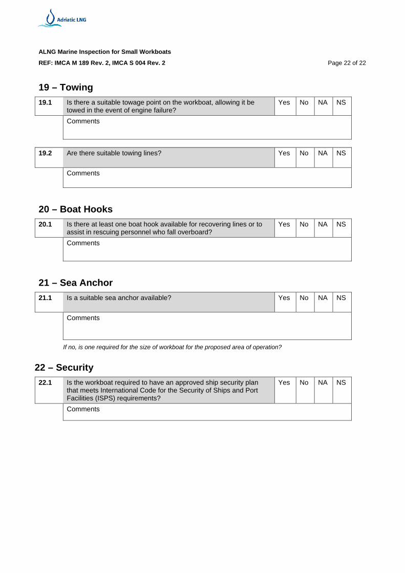
REF: IMCA M 189 Rev. 2, IMCA S 004 Rev. 2 Page 1 of 22
Marine Inspection for Small Workboats (Common Marine Inspection Document for Small Workboats)
Introduction
Purpose The purpose of this ALNG-approved document is to provide an ALNG basic marine inspection standard for workboats which are used in the North Adriatic Sea and are less than 500 gross tonnage or less than 50 meters in length (or both) and are, therefore, not required to have either an International Safety Management or an International Ship Security Certificate, although the principles outlined within the two codes are worth following.
In this document small workboat means a small vessel in commercial use, other than for sport, pleasure, pilot duties, surveying of harbours, and their approaches or dredging. These small workboats could be used for various appropriate tasks such as offshore.
ALNG Inspector's Name:
Workboat Name:
IMO Number:
Date Inspected:
ALNG Marine Inspection for Small Workboats
REF: IMCA M 189 Rev. 2, IMCA S 004 Rev. 2 Page 2 of 22
Vessel Particular Name of vessel
IMO number
Type of vessel (include detail of any special features)
Previous name(s)
Vessel owner/operator
Name:
Address:
Tel:
Fax:
E-mail:
Date current vessel owner/operator assumed responsibility for vessel
Flag
Port of registry
Classification society (if the vessel has changed class within the past six months, report date of change and previous classification society)
Class ID number
Workboat certificate details
Issued
Issued by
Valid until
Category
Last annual exam performed (valid if issued within past 12 months) by
Additional comments/observations
ALNG Marine Inspection for Small Workboats
REF: IMCA M 189 Rev. 2, IMCA S 004 Rev. 2 Page 3 of 22
Index of Certificates and Documents
Certificates
Applicable to Vessel Type Y/N
Date of Expiry
Cert Does Not Expire
Flag state certificate(s) Classification society certificate(s) Radio station licence Servicing certificate – life raft #1 Servicing certificate – life raft #2 Servicing certificate – life raft #3 Servicing certificate – life raft #4 Hydrostatic release certificate – life raft #1 Hydrostatic release certificate – life raft #2 Hydrostatic release certificate – life raft #3 Hydrostatic release certificate – life raft #4 Certificates of insurance – Employer’s liability Certificates of insurance – Hull and machinery Certificates of insurance – P&I Certificates of test and thorough examination of lifting equipment
Last independent inspection of lifting equipment 1 – Inspection 1.1 Has the vessel been subject to a Coast Guard control since the
previous inspection? Yes No NA NS
Comments
Where and when was the inspection carried out? If vessel was detained, or significant deficiencies were listed, record the reason for detention or nature of those deficiencies.
1.2 Is there any independent certificate of inspection of the vessel
available? Yes No NA NS
Comments
ALNG Marine Inspection for Small Workboats
REF: IMCA M 189 Rev. 2, IMCA S 004 Rev. 2 Page 4 of 22
2 – Logbooks 2.1 Does the vessel have a radio logbook? Yes
No
NA
NS
Comments
2.2 Does the vessel have appropriate logbook/s (for example, official,
deck, engine)? Yes No NA NS
Comments
3 – Weather-tight Integrity 3.1 Is it possible to secure all openings to prevent the ingress of water
while at sea? Yes No NA NS
Comments
3.2 Are doors located above the weather deck, which give access to
spaces below, weather-tight and able to be operated from either side?
Yes No NA NS
Comments
3.3 If there are any opening skylights fitted, can they be effectively
secured from either side? Yes No NA NS
Comments
ALNG Marine Inspection for Small Workboats
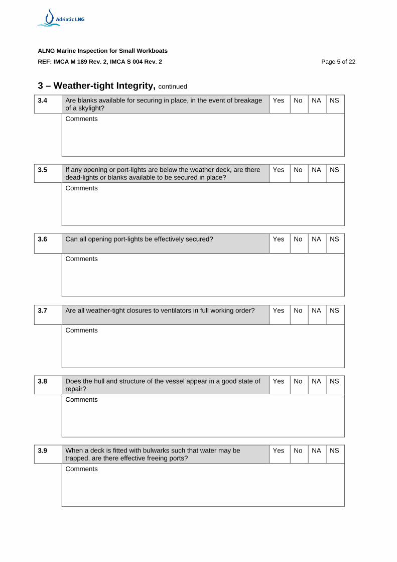
REF: IMCA M 189 Rev. 2, IMCA S 004 Rev. 2 Page 5 of 22
3 – Weather-tight Integrity, continued 3.4 Are blanks available for securing in place, in the event of breakage
of a skylight? Yes No NA NS
Comments
3.5 If any opening or port-lights are below the weather deck, are there
dead-lights or blanks available to be secured in place? Yes No NA NS
Comments
3.6 Can all opening port-lights be effectively secured? Yes
No
NA
NS
Comments
3.7 Are all weather-tight closures to ventilators in full working order? Yes
No
NA
NS
Comments
3.8 Does the hull and structure of the vessel appear in a good state of
repair? Yes No NA NS
Comments
3.9 When a deck is fitted with bulwarks such that water may be
trapped, are there effective freeing ports? Yes No NA NS
Comments
ALNG Marine Inspection for Small Workboats
REF: IMCA M 189 Rev. 2, IMCA S 004 Rev. 2 Page 6 of 22
3 – Weather-tight Integrity, continued 3.10 Are sea inlets and discharges below the waterline fitted with a
seacock or other effective means of closure? Yes No NA NS
Comments
3.11 Is there evidence of any water leaking into the vessel below decks?
Yes No NA NS
Comments
4 – Machinery and Electrical 4.1 Are the engine/generator and the space in which it is sited clean
and well maintained? Yes No NA NS
Comments
4.2 Are vent pipes for fuel tanks protected against water ingress by a
goose neck or other efficient means? Yes No NA NS
Comments
4.3 Are vent pipes for fuel tanks protected against flame ingress by a
suitable gauze diaphragm? Yes No NA NS
Comments
4.4 Are there means available to effectively control fuel spillages or
leaks from permanent or temporary equipment? Yes No NA NS
Comments
4.5 Is there a safe means of isolating the fuel supply in the event of an
emergency? Yes No NA NS
Comments
ALNG Marine Inspection for Small Workboats
REF: IMCA M 189 Rev. 2, IMCA S 004 Rev. 2 Page 7 of 22
4 – Machinery and Electrical, continued 4.6 Are there any fuel or oil leaks in the machinery spaces? Yes
No
NA
NS
Comments
4.7 Are the bilges free from oil? Yes
No
NA
NS
Comments
4.8 When batteries are the sole means of starting the propulsion
engine, are there at least two sets of batteries available? Yes No NA NS
Comments
4.9 Are there safe means of isolating electrical supplies? Yes
No
NA
NS
Comments
4.10 Are electrical systems protected from water?
Are they marked as CE approval? Yes No NA NS
Comments
4.11 Are battery spaces adequately ventilated? Yes
No
NA
NS
Comments
4.12 Is the battery cut-off switch operational? Yes
No
NA
NS
Comments
4.13 Are all batteries secured firmly to prevent movement? Yes
No
NA
NS
Comments
ALNG Marine Inspection for Small Workboats
REF: IMCA M 189 Rev. 2, IMCA S 004 Rev. 2 Page 8 of 22
4 – Machinery and Electrical, continued 4.14 Is effective emergency lighting provided to allow escape from
under-deck and to allow essential activities to continue? Yes No NA NS
Comments
4.15 Is effective emergency lighting provided to illuminate survival craft
launching and embarkation areas? Yes No NA NS
Comments
4.16 Is effective emergency lighting provided to illuminate man-
overboard rescue equipment and rescue areas? Yes No NA NS
Comments
4.17 If steering by remote control, are there effective means of
emergency steering? Yes No NA NS
Comments
4.18 Are there two fully working bilge pumps? Yes
No
NA
NS
Comments
4.19 Is at least one bilge pump available for duty in an emergency? Yes
No
NA
NS
Comments
5 – Stability
5.1 Does the vessel have an approved stability information booklet? Yes
No
NA
NS
Comments
5.2 Is a competent person available to calculate the vessel's stability? Yes
No
NA
NS
Comments
ALNG Marine Inspection for Small Workboats
REF: IMCA M 189 Rev. 2, IMCA S 004 Rev. 2 Page 9 of 22
5 – Stability, continued
5.3 Are any stability records available to show the effects of adding or removing loads on the vessel?
Yes No NA NS
Comments
5.4 Are the crew familiar with the stability issues with regards to
winches and lifting operations? Yes No NA NS
Comments
6 – Freeboard 6.1 Is the vessel marked with a deck line and freeboard mark? Yes
No
NA
NS
Comments
6.2 If the vessel is not marked with a deck line and freeboard mark, has
the safe maximum draft been determined? Yes No NA NS
Comments
7 – Escape
7.1 Are there at least two means of escape from any manned or occupied space?
Yes No NA NS
Comments
7.2 If there are not at least two means of escape, are there fire
detectors? Yes
No
NA
NS
Comments
7.3 Are means of escape clearly marked? Yes
No
NA
NS
Comments
ALNG Marine Inspection for Small Workboats
REF: IMCA M 189 Rev. 2, IMCA S 004 Rev. 2 Page 10 of 22
8 – Fire 8.1 Are fire detectors, where fitted, working? Yes
No
NA
NS
Comments
8.2 Are the fire detectors, where fitted, tested on a regular basis? Yes
No
NA
NS
Comments
8.3 If no fire detectors are fitted, are adequate procedures in place to
detect smoke or fire? Yes No NA NS
Comments
8.4 Is the fire pump working? Yes
No
NA
NS
Comments
This may be a manual or power driven pump. 8.5 Can the fire hose deliver a jet of water to any part of the vessel? Yes
No
NA
NS
Comments
8.6 Does the jet and spray nozzle work on the fire hose? Yes
No
NA
NS
Comments
8.7 Are there at least two multi-purpose fire extinguishers on the
vessel? Yes No NA NS
Comments
8.8 Do the extinguishers appear in good condition and maintained
properly inspected? Yes No NA NS
Comments
ALNG Marine Inspection for Small Workboats
REF: IMCA M 189 Rev. 2, IMCA S 004 Rev. 2 Page 11 of 22
8 – Fire, continued 8.9 Is there a fixed means of discharging a fire-extinguishing medium to
the engine room? Yes No NA NS
Comments
If there is no fixed means of discharging a fire-extinguishing medium to the engine room how would an engine room fire be extinguished?
8.10 Are there at least two fire buckets with lanyards? Yes
No
NA
NS
Comments
8.11 Is there a fire blanket in the galley or cooking area? Yes
No
NA
NS
Comments
8.12 Does the crew know how to operate the fire fighting equipment? Yes
No
NA
NS
Comments
9 – Radio 9.1 Is there a fixed radio installation fitted with digital selective calling
(DSC)? Yes
No
NA
NS
Comments
For category 6 vessels recommendation only. 9.2 Is a medium frequency single side band (MF SSB) radio telephone
with DSC fitted? Yes No NA NS
Comments
Recommended for category 0, 1, and 2 vessels. 9.3 Is an emergency position indicating radio beacon (EPIRB) fitted? Yes
No
NA
NS
Comments
ALNG Marine Inspection for Small Workboats
REF: IMCA M 189 Rev. 2, IMCA S 004 Rev. 2 Page 12 of 22
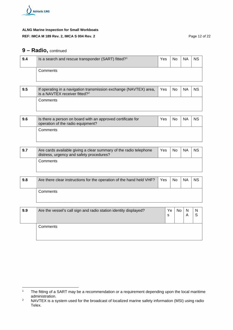
9 – Radio, continued 9.4 Is a search and rescue transponder (SART) fitted?1 Yes
No
NA
NS
Comments
9.5 If operating in a navigation transmission exchange (NAVTEX) area,
is a NAVTEX receiver fitted?2 Yes No NA NS
Comments
9.6 Is there a person on board with an approved certificate for
operation of the radio equipment? Yes No NA NS
Comments
9.7 Are cards available giving a clear summary of the radio telephone
distress, urgency and safety procedures? Yes No NA NS
Comments
9.8 Are there clear instructions for the operation of the hand held VHF? Yes
No
NA
NS
Comments
9.9 Are the vessel’s call sign and radio station identity displayed? Ye
s
No
NA
NS
Comments
1 The fitting of a SART may be a recommendation or a requirement depending upon the local maritime
administration. 2 NAVTEX is a system used for the broadcast of localized marine safety information (MSI) using radio
Telex.
ALNG Marine Inspection for Small Workboats
REF: IMCA M 189 Rev. 2, IMCA S 004 Rev. 2 Page 13 of 22
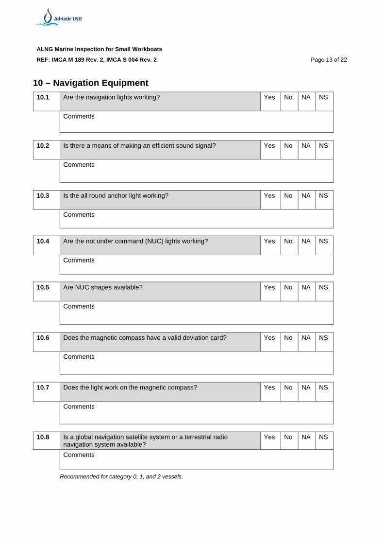
10 – Navigation Equipment 10.1 Are the navigation lights working? Yes
No
NA
NS
Comments
10.2 Is there a means of making an efficient sound signal? Yes
No
NA
NS
Comments
10.3 Is the all round anchor light working? Yes
No
NA
NS
Comments
10.4 Are the not under command (NUC) lights working? Yes
No
NA
NS
Comments
10.5 Are NUC shapes available? Yes
No
NA
NS
Comments
10.6 Does the magnetic compass have a valid deviation card? Yes
No
NA
NS
Comments
10.7 Does the light work on the magnetic compass? Yes
No
NA
NS
Comments
10.8 Is a global navigation satellite system or a terrestrial radio
navigation system available? Yes No NA NS
Comments
Recommended for category 0, 1, and 2 vessels.
ALNG Marine Inspection for Small Workboats
REF: IMCA M 189 Rev. 2, IMCA S 004 Rev. 2 Page 14 of 22
10 – Navigation Equipment, continued 10.9 Is there means of measuring the distance covered? Yes
No
NA
NS
Comments
Recommended for category 0, 1, and 2 vessels. 10.10 Is the echo sounder working? Yes
No
NA
NS
Comments
10.11 Are current, corrected charts available? Yes
No
NA
NS
Comments
An electronic chart plotting system complying with appropriate maritime administration requirements may be acceptable.
10.12 Are current tide tables available? Yes
No
NA
NS
Comments
10.13 Is there a tidal stream atlas available for the area of operation? Yes
No
NA
NS
Comments
10.14 Is there a copy of the list of radio signals available for the area of
operation? Yes No NA NS
Comments
10.15 Is a copy of the International Code of Signals available? Yes
No
NA
NS
Comments
10.16 Is an efficient waterproof signalling lamp suitable for Morse
signalling provided? Yes
No
NA
NS
Comments
ALNG Marine Inspection for Small Workboats
REF: IMCA M 189 Rev. 2, IMCA S 004 Rev. 2 Page 15 of 22
10 – Navigation Equipment, continued 10.17 Is an efficient radar reflector fitted? Yes
No
NA
NS
Comments
10.18 Is there a working fixed or portable searchlight for a vessel that may
operate in darkness? Yes No NA NS
Comments
10.19 Does the vessel have sufficient anchor cable for the proposed area
of operation? Yes No NA NS
Comments
11 – Navigation 11.1 Is the vessel provided with operator policy statements, instructions
and procedures with regard to safe navigation? Yes No NA NS
Comments
11.2 Does the vessel have written procedures for entry into a 500-meter
Terminal zone? Yes No NA NS
Comments
11.3 Are up-to-date navigation warnings and weather forecasts
available? Yes No NA NS
Comments
12 – Protection of Personnel 12.1 Is there a safe means of access to the workboat? Yes
No
NA
NS
Comments
ALNG Marine Inspection for Small Workboats
REF: IMCA M 189 Rev. 2, IMCA S 004 Rev. 2 Page 16 of 22
12 – Protection of Personnel, continued
12.2 Are there adequate guardrails around the deck? Yes
No
NA
NS
Comments
12.3 Are there at least two safety harnesses on board and additional
harnesses for all those required to work on deck? Yes No NA NS
Comments
12.4 Is the surface of the working deck non-slip? Yes
No
NA
NS
Comments
12.5 Are personnel provided with protective clothing appropriate to the
prevailing air and sea temperatures? Yes No NA NS
Comments
12.6 If the mean seawater temperature is 10°C or less, is there an
approved survival suit for each person on board? Yes No NA NS
Comments
12.6 What measures have been taken to prevent personnel being
exposed to excessive noise? Yes No NA NS
Comments 12.7 Are noise-warning signs posted as appropriate? Yes
No
NA
NS
Comments
12.8 Is a safety briefing given to all personnel who go on a voyage
covering such items as use of life jackets and procedures to be followed in the case of an emergency?
Yes No NA NS
Comments
12.9 In the event of collision, grounding, fire, explosion, gas, or toxic
vapor release, are adequate written emergency procedures in place?
Yes
No
NA
NS
Comments
ALNG Marine Inspection for Small Workboats
REF: IMCA M 189 Rev. 2, IMCA S 004 Rev. 2 Page 17 of 22
12 – Protection of Personnel, continued
12.10 Are adequate medical stores provided? Yes
No
NA
NS
Comments
13 – Crane 13.1 Is there a valid test certificate for the crane if fitted? Yes
No
NA
NS
Comments
13.2 Is there a competent crane operator on board? Yes
No
NA
NS
Comments
14 – Manning 14.1 Does the person in command hold an appropriate certificate of
competency? Yes No NA NS
Comments
14.2 Is there a second person on board deemed experienced by the
person in command? Yes No NA NS
Comments
14.3 Is there a person on board familiar with the operation and
maintenance of the main propulsion machinery? Yes No NA NS
Comments
14.4 Is there at least one person on board who holds an appropriate
certificate for the operation of the radio station? Yes No NA NS
Comments
14.5 Is there at least one person on board who holds an approved
medical first aid certificate? Yes No NA NS
Comments
ALNG Marine Inspection for Small Workboats
REF: IMCA M 189 Rev. 2, IMCA S 004 Rev. 2 Page 18 of 22
14 – Manning, continued 14.6 Has the person in command attended an approved stability course
for workboats or is he or she able to satisfy the flag and coastal state, or other independent body, that he or she has adequate knowledge?
Yes No NA NS
Comments
14.7 Has the person in command and any member of the crew who is
liable to use the radar undertaken appropriate training in its use? Yes No NA NS
Comments
14.8 Are the crew members able to satisfactorily demonstrate operation
of life saving appliances and fire-fighting equipment? Yes No NA NS
Comments
15 – Reporting
15.1 Are accidents and incidents investigated and reported in accordance with relevant flag state or coastal state (or both) requirements?
Yes No NA NS
Comments
15.2 Have there been any accidents or incidents on the workboat in the
last 12 months? Yes No NA NS
Comments
15.3 If there have been any accidents or incidents, are reports
available? Yes No NA NS
Comments
16 – Clean Seas
16.1 Are adequate arrangements in place to prevent the discharge of sewage in prohibited areas?
Yes No NA NS
Comments
ALNG Marine Inspection for Small Workboats
REF: IMCA M 189 Rev. 2, IMCA S 004 Rev. 2 Page 19 of 22
16 – Clean Seas, continued
16.2 Are prohibited areas for sewage discharge identified? Yes
No
NA
NS
Comments
16.3 Are arrangements in place for the retention of garbage on board? Yes
No
NA
NS
Comments
16.4 Are arrangements in place for the handling of oily wastes? Yes
No
NA
NS
Comments
16.5 Are arrangements in place for the prevention of discharge of
oil/oil-contaminated water overboard? Yes No NA NS
Comments
17 – Life Saving Appliances 17.1 Are one or more life rafts onboard sufficient for the proposed
maximum personnel onboard (POB)? Yes No NA NS
Comments
If no life raft is fitted, what means are there in place to abandon the workboat at sea if required to do so? 17.2 Does or do the life raft(s) have a current certificate of examination? Yes
No
NA
NS
Comments
When is or are the life raft(s) next due for examination? 17.3 Are there sufficient life buoys for the type of operation and
workboat? Yes
No
NA
NS
Comments
ALNG Marine Inspection for Small Workboats
REF: IMCA M 189 Rev. 2, IMCA S 004 Rev. 2 Page 20 of 22
17 – Life Saving Appliances, continued 17.4 Are there sufficient life buoys with light for the type of operation and
workboat? Yes No NA NS
Comments
17.4 Do the life buoys have buoyant heaving lines? Yes
No
NA
NS
Comments
17.5 Is there a life jacket for every person carried on the workboat? Yes
No
NA
NS
Comments
17.6 Are there parachute flares onboard the workboat? Yes
No
NA
NS
Comments
17.7 Are there red hand flares onboard the workboat? Yes
No
NA
NS
Comments
17.8 Are there at least two buoyant or hand held smoke signals? Yes
No
NA
NS
Comments
17.9 Is there a thermal protective aid for every person carried on the
workboat? Yes No NA NS
Comments
17.10 Are there effective means to recover a person from the water? Yes
No
NA
NS
Comments
17.11 Are life-saving signal tables available? Yes
No
NA
NS
Comments
ALNG Marine Inspection for Small Workboats
REF: IMCA M 189 Rev. 2, IMCA S 004 Rev. 2 Page 21 of 22
17 – Life Saving Appliances, continued 17.12 Is there a means of sounding a general alarm in the event of an
emergency? Yes No NA NS
Comments
17.13 Does the general alarm operate satisfactorily? Yes
No
NA
NS
Comments
17.14 Is there a training manual for use of lifesaving appliances (LSAs)? Yes
No
NA
NS
Comments
17.15 Are there instructions for onboard maintenance of the LSA? Yes
No
NA
NS
Comments
17.16 Is a record of emergency drills maintained? Yes
No
NA
NS
Comments
17.17 Is there an up to-date onshore emergency response plan or
manual? Yes
No
NA
NS
Comments
18 – Mooring
18.1 Are there adequate mooring points on the workboat? Yes
No
NA
NS
Comments
18.2 Is there a sufficient number of mooring lines in good condition? Yes
No
NA
NS
Comments
ALNG Marine Inspection for Small Workboats
REF: IMCA M 189 Rev. 2, IMCA S 004 Rev. 2 Page 22 of 22
19 – Towing 19.1 Is there a suitable towage point on the workboat, allowing it be
towed in the event of engine failure? Yes No NA NS
Comments
19.2 Are there suitable towing lines? Yes
No
NA
NS
Comments
20 – Boat Hooks 20.1 Is there at least one boat hook available for recovering lines or to
assist in rescuing personnel who fall overboard? Yes No NA NS
Comments
21 – Sea Anchor 21.1 Is a suitable sea anchor available? Yes
No
NA
NS
Comments
If no, is one required for the size of workboat for the proposed area of operation?
22 – Security
22.1 Is the workboat required to have an approved ship security plan that meets International Code for the Security of Ships and Port Facilities (ISPS) requirements?
Introduction This chapter describes the Safety, Security, Health, and Environmental Management Systems (SHEMS) expectations for support vessel operations, including crew training, personal protective equipment (PPE), health management, emergency response, and incident investigation.
This chapter applies to ALNG and chartered vessels.
In this chapter This chapter contains the following information:
4.1 Safety Management Systems ............................................................................ 4-2
4.2 Crew Manning and Training ........................................................................... 4-4
4.3 Personal Protective Equipment (PPE) ............................................................ 4-7
Introduction All vessels operating at the ALNG offshore Terminal, of 500 gross tonnage and upwards are required to have a Safety Management System (SMS) in place that complies with the requirements of the International Safety Management Code per the International Maritime Organization (IMO) 1974 International Convention for the Safety of Life at Sea (SOLAS) and its amendments.
This code requires the Vessel and Vessel Operator to have an approved, structured, and documented SMS in place enabling personnel to implement effectively the Operators safety and environmental protection policy.
Each vessel must have a Safety Management Certificate issued to the vessel by an approved authority which signifies that the contractor and its shipboard management operate in accordance with the approved Safety Management System.
Vessels less than 500 gross tonnage or non SOLAS vessels
Vessels of less than 500 gross tonnage or non-SOLAS vessels operating at the ALNG offshore Terminal must have a comprehensive SMS in place that is based on the principles and requirements of the International Safety Management Code and should include:
Safety and Environmental Policies Risk management plans Qualifications and responsibilities of Company and key personnel SHEMS training and testing program Job Safety Analysis program Contingency, response plans, and drills Hazard identification, mitigation, injury prevention, and permit to work system Waste management plan Regulatory compliance documentation Personal protective equipment Oversight and audit program Competency or proficiency evaluation including IMO Standards for Training,
Certification, and Watchkeeping (STCW) Incident investigation Occupational health program Environmental program Critical equipment maintenance and testing programs Security plan Internal Auditing
The Vessel Operator or Owner should have in place a Quality Assurance Program based on the principles and requirements of International Organization for Standardization (ISO) 9001 or its most current replacement or equivalent quality management systems as applicable to the operation and area of operations and services.
The program should define measures to ensure or control quality of service including:
Project control and deliverables Detection, analysis, and control of observed or noted nonconformities Internal and subcontractor auditing plans Maintenance history record for critical equipment Plan for technical inspections and approvals of equipment Document control and records filing, maintenance, and retention process Management of change process
Safety meeting The Vessel Operator must have procedures in place for conducting regular, documented onboard safety meetings to communicate SMS expectations and lessons learned from safety incidents.
Records The Vessel Operator and Master must maintain accurate logs or records of activity, inspections and tests, including deck, engine, and emergency drills, safety meetings, and so forth.
Drug and Alcohol Policy
The Vessel Operator or owner, during the validity of the Agreement with ALNG, must adopt a drug and alcohol policy.
All vessel officers and crew must have the qualifications, experience, and licenses that satisfy vessel flag and port state requirements, IMO International Convention on STCW, 1995 and all subsequent amendments. The Vessel Operator must have a system in place to verify the authenticity of officer and crew certificates and licenses.
Crew training and competency
The Vessel Operator should have in place a system for training and qualification to ensure that vessel personnel are properly qualified and competent for the work performed. For specialized positions such as the Dynamic Position operator, crane driver, rigger, banksman, and helideck crew, documented evidence that competency has been assessed by an appropriate authority must be maintained.
The Vessel Operator must maintain onboard the vessel a comprehensive personnel training plan that includes:
The minimum licensing, training, and certification by position Shore device workers training Training program, including refresher training and records for all crew members,
including competency and proficiency evaluation
The Vessel Operator should develop a vessel crew matrix specific to each vessel class that establishes the minimum experience and certification(s) required for each position.
These programs and records should be subjected to periodic assessment or audit by the ALNG Senior Marine Advisor.
Company specific training
As appropriate, ALNG implements a training program to ensure and document that relevant marine crews receive ALNG required training related specifically to the operation in that region. Examples include:
Operation of specialized evacuation equipment Deployment and operation of oil spill response (OSR) equipment Personnel transfer equipment (such as, FROG, personnel net, and so forth) ALNG Company Internal Safety Training (CIST) Force Interactive Tug Simulation course (for Loading Masters, Pilots and Tug
During the vessel bid process ALNG identifies any specialized crew training or certification requirements that the Vessel Operator must provide above and beyond flag and port state requirements. This may include:
Rigger training OSR training Pilotage exemption for ports of operation if applicable Changes via helicopter Hazardous material shipping and handling Other Offshore Petroleum Industry Training Organization (OPITO) training as
The Vessel Operator must provide sufficient officer and crew for continuous 24-hour operations throughout the assignment, ensuring manning levels comply with flag and port state requirements and the requirements of STCW, 1995 and all subsequent amendments.
Manning level, experience, and qualification requirements should be reviewed during the vessel bid tender phase to ensure they meet work scope and vessel manning requirements for operations within the 500-meter safety (exclusion zone) zone.
The Vessel Operator should maintain a vessel crew matrix detailing certification held, number of years' experience in rank, on type of vessel and with company for officers' positions per requirements of STCW, 1995.
ALNG may establish additional minimum experience requirements for certain critical positions.
When reviewing manning level requirements the following should be considered:
Bridge manning requirements: the Marine Collision Avoidance Best Practice recommends that all vessels underway within the established safety zone should have a minimum of two qualified persons (officer and look-out) on the bridge, and at least one should be a certified bridge watch-keeping Officer.
Depending on the type of operations, two or more qualified officers might be required on the bridge.
Deck manning requirements during offshore offloading or loading operations. Engine room manning requirements: recommendation that engine room is manned
when operating in the 500-meter safety zone. Specialized work activity requirements (for example, OSR, rescue and evacuation
capabilities, anchor handling activities, and so forth). Requirements of STCW, 1995 and all subsequent amendments, particularly with
respect to Chapter VIII, Section A-VIII/1 "Fitness for duty," which address hours rest; or D.L. 271/99 (Italian Law) or International Labor Organization (ILO).
Arrangements with the Vessel Operator whereby temporary increases in manning levels can be requested when special work activities arise should be considered.
Security sensitive positions
The Vessel Operator is required to obtain background checks on its employees or subcontractors performing security sensitive services. ALNG develops a list, as required, of positions considered as security sensitive. These should include:
Captain (Master) First or Chief Officer Chief Engineer
All vessel personnel must use PPE as directed by the Vessel Operator Safety Management System. All PPE proposed for use by the contractor must be approved by the ALNG Safety, Health, and Environment (SHE) Advisor. It is recommended that the Vessel Operator maintain a matrix of PPE use requirements for each specific work activity or work location (or both).
PPE must include at a minimum:
Certified hard hat (or certified bump hats for personnel working in the engine room or other machinery spaces)
High-visibility boiler suits Ear protection, including double attenuation protection in high noise areas Eye protection (side shields, goggles, and face shields where dictated by task) Steel or composite toe safety boots Safety gloves (hand protection) Safety harness (fall protection) Additional PPE may be required to mitigate hazards associated with specific tasks Personal floatation devices (PFDs) to be included as appropriate per the specific
Job Safety Analysis (JSA)
Personal floatation devices
All vessel crew working on exposed decks such as the cargo deck or foredecks must wear approved PFDs with current validity.
Night time operations during cargo handling
To provide maximum visibility to the Terminal crane operators and crew, vessel crews working cargo or personnel transfers offshore during darkness or restricted visibility must wear high-visibility boiler suits (coveralls) or jackets.
It is also recommend that the deck crews wear personalized lights on the helmets or jackets to enhance visibility.
Cold weather clothing
Where environmental conditions dictate, Vessel Operators should consider providing warm and waterproof clothing and survival suits to crews working in exposed areas.
The Vessel Operator should have in place a comprehensive risk assessment process for assessing the general risk levels of the varying vessel operations and activities and identifying mitigation measures.
JSA A Job Safety Analysis (JSA) process must be in place and utilized by the vessel's Master and crew. A generic set of JSAs for routine operations should be maintained onboard with updates made when work place changes occur. New JSAs must be developed prior to the start of non-routine operations.
Records should be maintained onboard for ALNG review.
LPSA and toolbox meetings
Loss prevention self-assessments (LPSAs) (stop and think before acting), toolbox safety meetings, and pre-task walk-throughs should be utilized onboard.
Permit to work Vessels must be operated under a documented permit to work (PTW) system, which must include:
Hot work Working over the side or at heights Enclosed or confined space entry Energy isolation or lock out / tag out Diving (if applicable) Breaking containment Critical equipment or systems Cold work
If the vessel owner or operator assigns work activities to third parties (subcontractors) this process must comply with SHEMS 8A requirements. The ALNG operational contract administrator should approve any subcontractor forms completed by the contractors, and so advise the ALNG Agreement owner.
ALNG's permit to work (PTW) system must be used in all cases when work is being carried out, inside the safety zone, on a vessel by a contractor, subcontractor, or any other personnel who is either employed by the vessel or ALNG.
Where the subcontractor's PTW system is to be used for work specific to the subcontractors work activity (for example diving and so forth), there must be an agreed bridging document in place that identifies respective roles and responsibilities.
Tank cleaning activities conducted by a subcontractor should be conducted under the vessels PTW system and included as part of the tool box meeting.
Permit requirements within the 500-meter zone
When performing routine operations within the 500-meter safety (exclusion) zone, the vessel continues to work under ALNG's permit to work system and with continued communication with the Terminal Control Room Operator (CRO).
Work not associated with the direct task, such as vessel maintenance activities must not be conducted while the vessel is within the 500-meter zone.
Specialized work (including diving, remotely operated vehicle [ROV] operations, maintenance support, and so forth) within the 500-meter zone or other ALNG-stewardable site is managed through this Marine Operations Manual with additional arrangements where specific work permit approval responsibilities are addressed.
The Vessel Operator must have a health management system that addresses the protection of the health of its employees, subcontractors, passengers, and ALNG personnel onboard the vessel.
The health management system should, manage health risks by:
Identifying health hazards, and assessing and controlling risks. Providing the appropriate PPE to protect the crew from substances that may pose
a potential health hazard and noise risks in the workplace. Assessing fitness to work to ensure personnel are medically fit to perform all
duties specified for their job function without undue risk to themselves and others. Performing health assessments of exposed workers and where appropriate setting
exposure limits for any physical agents and chemical substances at the work site. Providing clinical management of occupational illnesses and injuries, and
ensuring appropriate preparations for assigned locations including vaccinations, personal medical supplies and prescriptions and education about local and public health risks.
Providing access to quality clinical services as appropriate. Effectively communicating health risks and prevention strategies to all workers. Retaining health records, including work history, exposure monitoring, and
medical information, in suitably accessible forms while respecting security and medical confidentiality considerations.
The system should address the health risks associated with:
Hot and cold climates Working hours and schedules Drug and alcohol use H2S (for example, oily water carried by crew supply vessel [CSV]) Hazardous substances Infectious and vector-borne diseases Food and water safety Noise
Note: The system must be in accordance with D.L. 271/99 and Hazard Analysis Critical Control Point (HACCP) /D.L. 135/99.
Smoking Smoking and non-smoking areas should be clearly identified. Note: Smoking is prohibited outside vessel quarters or machinery spaces when the vessel is in the 500-meter safety zone.
Medical emergencies occurring onboard the vessel must immediately be notified to the vessel owner per their established internal reporting procedure. The owner must promptly submit appropriate information to the ALNG Senior Marine Advisor or Management.
Noise levels The Vessel Operator should maintain records of vessel noise surveys. Appropriate signage must be posted on vessels to alert crews of high noise areas.
Food safety and hygiene
Crew personnel tasked with handling and preparation of food should be provided with training by the Vessel Operator in personal hygiene and food service sanitation.
Documented training should include:
Personal safety and use of protective clothing and other PPE Personal hygiene Food hygiene and nutrition Prevention of bacterial food poisoning Preparation and service of food Food storage Cleaning and waste handling
HACCP Vessels hired for the primary purpose of accommodating Charterer personnel or contractors or vessels which frequently accommodate Charterer personnel, should have in place a documented Hazard Analysis and Critical Control Point (HACCP) system for food, fresh water, and hygiene control. The HACCP system should identify critical control points and the specific actions to be taken at those points.
The Vessel Operator must have in place processes and procedures, which may be part of the vessel's planned maintenance system, which ensures a safe fresh water supply. Where applicable this also applies to vessels engaged in the supply of potable water to the Terminal. Potable water tanks must be solely dedicated to carriage of fresh water.
Processes and procedures should include:
Fresh water loading and supply arrangements Onboard water treatment Fresh water storage Fresh water testing requirements Fresh water from water-making plant, where applicable Appropriate methods for cleaning potable water tanks in the event of an
inadvertent contamination
Non-potable and fresh water supplies must be clearly identified.
The Vessel Operator must at all times follow port or flag state requirements.
ALNG health inspection
Regular health inspections of the vessel are conducted by the ALNG Senior Marine Advisor, or designee, including, where applicable:
Vector control program Drinking water sanitation Food sanitation Chemical handling procedures Waste management Medical services Industrial hygiene practices
ALNG may elect to conduct periodic health inspections of vessels, in particular where vessels are used for accommodating ALNG personnel or Contractors. Findings from health inspections should be provided to the Vessel Operator who should develop corrective action plans and track action items to closure in a timely manner.
Statutory health inspections
All vessels are under the control of the Maritime Authority as per national and International law, and therefore, subject to health inspections by the appropriate associated agencies.
Every vessel must have procedures and instructions in place for oil spill response preparedness.
Vessels over 400 gross tonnage are required to carry an approved Shipboard Oil Pollution Emergency Plan (SOPEP). Vessels over 150 gross tonnage certified to carry noxious liquid substances in bulk are required to carry an approved Shipboard Marine Pollution Emergency Plan (SMPEP).
Oil clean up and drills involving chemical clean up should be regularly conducted.
Waste management
Vessels must have in place a garbage management plan and Garbage Record Book which details the types and amounts of waste disposed of or incinerated with date, time, and position of vessel. Where garbage is disposed of to a shore facility, receipts for waste must be provided and retained in the garbage record book.
The Vessel Operator must provide clear instructions and facilities for segregation of garbage with particular consideration to "special waste" such as batteries, sensors, florescent tubes, and any generated biohazards, to ensure compatible materials are stowed together.
Oil Record Book
As per International Convention for the Prevention of Pollution from Ships (MARPOL) requirements, all vessels greater than 400 gross tonnage are required to complete Part 1 of the Oil Record Book to record machinery space operations. Vessels less than 400 gross tonnage should maintain an equivalent Oil Record Book to record machinery space oil and fuel related operations.
The Oil Record Book is used to record fuel loading and transfer operations and disposal of oily water or other oily residue either via the approved oily water separator or to shore reception facilities.
Where oily water or oily residue is disposed of at a reception facility, the facility must provide a receipt which is attached to the Oil Record Book.
Oil water separator
Vessels fitted with a 15-ppm oil water separator must maintain this equipment in good order.
Clear warning notices must be posted which warn against the overboard valve from the oil water separator being opened without the Chief Engineer's or Master's approval. This valve must be locked.
MARPOL requirements
The Vessel Master and crews must strictly comply with the MARPOL oil water discharge restrictions applicable to the area of operations in which the vessel is currently working.
The Vessel Operator is required to follow the incident reporting requirements as stated within the vessel contract terms.
An incident reporting matrix, detailing Vessel Operator and ALNG contact information should be maintained as part of the Contractor coordination procedure or interface management plan.
Initial incident notification format
Upon notification of an incident onboard a vessel or an LNGC (only when at the Terminal), ALNG initiates its incident reporting process. The vessel owner must adopt a similar process and internally report the incident including at least:
Date and time of incident Location Type of incident (reportable injury, equipment failure or damage, fire or
explosion, first aid, security related, serious near miss, other) Number and name or position of any injured personnel Brief description of the incident Response measures taken Impact (include effect on activities and operations, expected recovery, and
potential lost time for injured personnel) Assistance required, if any External authorities notified Media involvement Lead Operator Contact details
Incident reports to authorities
The Vessel Operator is responsible for complying with all local and flag state regulatory requirements in the reporting of an accident involving the vessel.
Follow up reports
Depending upon the seriousness of the incident, the Vessel Operator may be required to provide a written report within 24 hours of the incident. The final report should identify the root cause of the incident utilizing an acceptable process like Root Cause Analysis.
After the incident site has been secured and if possible within 24 hours following the incident, an investigation should be initiated by the Vessel Operator.
The Vessel Operator should assemble a team of personnel with the appropriate knowledge and background. The investigation team, the composition of which depends on the level and severity of the incident, should gather physical evidence and information from observations, interviews, and other relevant documentation, for example, logs, records, and procedures.
The information gathered should be analyzed and evaluated using a structured process (for example, Tap Root®) to establish pre-incident conditions, determine the sequence of events, identify root causes, and develop recommended corrective actions.
A report must be completed by the Vessel Operator to communicate the incident investigation findings, meet regulatory and government reporting requirements, and document recommendations to prevent reoccurrence.
The final report should include the following information:
Date and time of incident Date of the investigation List of investigation team members Description of the incident Facts determined during the investigation Causes of the incident Recommended corrective actions to help prevent recurrence
ALNG may request to be represented on the investigation team or conduct an independent investigation. Legal guidance and a Terms of Reference should be agreed.
The ALNG Senior Marine Advisor; Safety, Health, and Environment (SHE) Advisor; or other ALNG designated personnel; should form part of the investigation team, providing Marine expertise.
Classification of incidents
Clear guidance should be provided to the Vessel Operator on classification of incidents for ALNG internal reporting requirements, noting that the Vessel Operator may use a different method of classification for its own internal reporting.
ALNG classification of incidents is determined per SHEMS 9A.
Every vessel must have contingency plans, procedures, and instructions in place for emergency preparedness. Muster Station bills must be posted.
Vessel crews must be trained and competent to put into practice the emergency preparedness procedures.
Regular emergency response drills should be performed and recorded. The following types of drills should be conducted.
Fire Man overboard Abandon ship Search and rescue Security (vessels over 500 gross tonnage [GT], and the ALNG crew supply vessel
[CSV], adopt the basic requirements as per International Code for the Security of Ships and Port Facilities [ISPS])
Oil spill Loss of engine or steering power
In addition, vessel crews should be regularly trained in the use of life-saving equipment.
Emergency response coordination
ALNG Emergency Response Plans (ERPs) should include emergency scenarios involving marine support vessels. These may include:
Collision between Vessel and the Terminal, Shore Base Quay, or other location Overdue Marine Vessel Oil spill during transfer operations
Scenario based emergency drills with specific objectives should be conducted among ALNG, Vessel Operator, and Vessel to test communications, the ERP, and coordination between involved parties.
The specific roles and duties of all marine support vessels utilized in the event of an emergency should be documented in the ALNG ERP.
As part of the on-hire briefing and orientation process, ALNG should review with the Vessel Operator the ALNG ERP and ALNG's expectations of support vessels during different casualty events. The Vessel Operator should be provided with documentation describing the specific roles and duties of all marine support vessels utilized in the event of an emergency in the ALNG ERP.
References: Terminal/Pipeline Emergency Response Plan Shore Base Emergency Response Plan Terminal/LNG Carrier & Other Marine Emergency Response Bridging
4.9 International Ship and Port Facility Security (ISPS) Code
Introduction The ISPS Code ensures the security of ships and port facilities. This is a risk management activity to determine what security measures are appropriate. An assessment of the risks must be made for each particular case.
Owners of vessels to be chartered, or under charter, must ensure to ALNG that their vessels are in compliance with the ISPS Code, as appropriate.
The Terminal and Shore Base must be in compliance with the ISPS Code, as required by local authorities.
Purpose of the ISPS Code
The ISPS Code provides a standardized, consistent framework for evaluating risk and enables governments to offset changes in threat with changes in vulnerability for ships and port facilities.
Security risk assessment
To begin the process, each contracting government (local authorities in cooperation with industry associations) conducts a port facility security risk assessment. The risk assessments have three essential components:
Identify and evaluate important infrastructure and assets that are critical to the port facility, as well as those areas or structures that, if damaged, could cause significant loss of life or damage to the port facility's economy or environment.
Identify the actual threats to those critical assets and infrastructure in order to prioritize security measures.
Address the vulnerability of the port facility by identifying its weaknesses in physical security, structural integrity, protection systems, procedural policies, communications systems, transportation infrastructure, utilities, and other areas within a port facility that may be a likely target.
Once this assessment is completed, the contracting government can accurately evaluate risk.
International Ship and Port Facility Security (ISPS) Code, Continued
ISPS ship and port security requirements
This risk management concept is embodied in the ISPS Code through a number of minimum functional security requirements for ships and port facilities.
Support vessels over 500 gross tonnage engaged on international voyages must have an approved Ship Security Plan which meets ISPS requirements. An International Ship Security Certificate (ISSC) must be carried onboard the vessel, and a designated ship security officer must be identified in the plan.
These requirements include the following:
Ship security plans Ship security officers Company security officers Certain onboard equipment
For port facilities, the requirements include:
Port facility security plans Port facility security officers Certain security equipment
In addition, the requirements for ships and for port facilities include:
Monitoring and controlling access Monitoring the activities of people and cargo Ensuring that security communications are readily available
Each ship (or class of ship) and each port facility presents different risks. The method in which they meet the specific requirements of this Code are determined and eventually approved by local authorities.
Vessels which are not required to have an approved Ships Security Plan because of tonnage or trading area must have security procedures in place.
Note: Vessels that have gross registered tonnage (GRT) < 500 tons are not required to be ISPS compliant.
ISPS security levels
In order to communicate the threat at a port facility or for a ship, the contracting government sets the appropriate security level. Security levels 1, 2, and 3 correspond to normal, medium, and high threat situations, respectively. The security level creates a link between the ship and the port facility since it triggers the implementation of appropriate security measures for the ship and for the port facility.
International Ship and Port Facility Security (ISPS) Code, Continued
Security alert levels
The following table shows a correlation between security levels identified under the ISPS Code, which is used by the Italian Coastguard, and the ALNG Security Color Code.
Security Level 2 High: Orange Security Level 3 Severe: Red
Security measures
Adequate security measures in port and at sea should be in place, including anti-piracy deterrence when applicable.
The Crew Supply Vessel which is employed for personnel transportation must be fitted with all items as per the ISPS code.
At the Shore Base there is a systematic approach to ISPS as all passengers in transit are submitted to personal metal detector screening and a luggage screening process.
Introduction This chapter describes operational procedures, requirements, and expectations for management and coordination of marine support vessel operations for the Adriatic LNG Terminal.
In this chapter This chapter contains the following information:
5.3 Port Requirements, Passage Planning and Navigation ............................... 5-13
5.3.1 Local Harbor Master and Port Requirements ...................................... 5-14 5.3.2 Passage Planning and Navigation ........................................................ 5-15
5.4 Vessel Voyage Log System (VLS) .................................................................. 5-17
Table 5-9 Support Vessel Weather Limitations ........................................................ 5-24
Table 5-10 Tug Service Primary and Secondary Contact Details ............................ 5-51
Table 5-11 FiFi Class Descriptions .......................................................................... 5-59
Table 5-12 Line Handler Service Primary and Secondary Contact Details .............. 5-65
Table 5-13 Documentation Transfers Between the Vessel Master, Senior Marine Advisor, and the Terminal ................................................................................ 5-66
Table 5-14 Pilotage Service Primary and Secondary Contact Details ...................... 5-73
Introduction This section describes expectations for Support Vessels regarding marine communications and the ALNG marine communication systems and their use.
Communica-tions
Vessels must be fitted with suitable means of voice communication with both the Marine Shore Base and the Terminal. This is typically via very high frequency (VHF) or ultra-high frequency (UHF) radios.
ALNG provides each vessel with communication protocol instructions, this includes:
VHF or UHF channels for communication with the Terminal and Shore Base or maintaining listening watch. ALNG may elect to supply and install UHF base stations and associated equipment on the vessel, which is returned on completion of the charter.
Mobile, municipality, and Iridium (satellite) or telephone contacts offshore and onshore.
The tugs and crew supply vessel (CSV) have the capability to receive and send electronic data, such as email, allowing ease of transmittal of vessel daily logs (Captains Log), voyage instructions, manifests, and so forth. Other vessels utilize their base offices to transmit electronic data as required.
Portable UHF or VHF units
Intrinsically safe portable or handheld VHF or UHF radio units (ALNG acceptable systems) are used onboard the vessels when operating within the Terminal safety zone which is a circle defined by a 1.1 nautical mile (2000 m) radius from the center of the Terminal.
Mobile phones Personal mobile phones should not be used, within 500-meters of the Terminal, by personnel on the open deck or engaged in vessel maneuvering or station-keeping duties on the bridge; the only exception may be in the case of an emergency as a back-up form of communication. The use of audio entertainment equipment should never impact the ability of the Watch Officer to keep a proper lookout, safely navigate the vessel, or hamper the Watch Officer's ability to monitor alarms or radio equipment.
Cellular phones may be used between the vessel and Shore Base when the vessel is alongside at the Shore Base.
Radio silence Vessels must have in place specific procedures for radio silence. Prior to the Terminal enforcing radio silence the vessel must be at the required minimum distance from the Terminal (usually 1000 meters) and remain outside until advised, maintaining listening watch on the designated channels.
During some Terminal operations, periods of absolutely no communication must be observed. Switch the vessel radar to off or to standby, and tune the medium frequency (MF) transmitter to minimum effect. The commencement and completion of radio silence is announced on Marine VHF channel 16.
Types of systems
The following marine-related communication systems are used by ALNG.
Table 5-1 Marine-related Communication Systems Used by ALNG
Radio Systems Telephone Systems Other Systems Marine VHF radios* Mobile and Iridium
(satellite) telephones Global Maritime Distress and Safety System (GMDSS)
The following are brief descriptions of the systems.
Table 5-2 Marine-related Communications Systems Description
Type Description UHF radios ALNG only system: The range of communication extends to all the
ALNG onshore facility locations in the Veneto region, and the radios are used for internal field communications such as crane-to-boat. A number of the Terminal UHF radios are capable of making phone calls through the private automatic branch exchange (telephone and communications) (PABX) system.
Marine VHF radios
Open public system: These radios are capable of communicating over a range of 40 km. They are used for shorter distance marine communication between vessels, the Terminal, and the Shore Base.
Aviation aero VHF radios
Open public system: These radios are capable of communicating over a range of 100 km depending on aircraft altitude. They are used for direct communication between offshore and Shore Base facilities, and helicopter (fixed and handsets available).
Cellular Phones
This system may have coverage offshore but should not be used as a system of communication between the Terminal and vessels. Cellular phones may be used between the vessel and Shore Base when the vessel is alongside at the Shore Base.
Note: There is not a GSM support antenna installed on the Terminal.
GMDSS This is the international marine emergency distress system.
The following VHF and UHF channels must be tested daily:
Preparedness and emergency Marine operations Air transport operations
Periods of radio silence are announced on channel 16 VHF. During radio silence there is to be absolutely no communication. The vessel's radar must be switched off or switched to standby and the MF transmitter tuned to minimum effect.
Voyage instructions
Roles and responsibilities for planning and issuing voyage orders and method of communication of the orders should be addressed for each vessel.
Voyage instructions should include:
Voyage plan (sequence of way points, non-return point, minimum safe distance from other vessels, and so forth)
Offloading or back loading activity (including quantities of bulk liquids) Copy of the vessel load list (manifest) List of dangerous goods and associated Material Safety Data Sheets (MSDSs) for
each call Special work activities (such as, stand-by, LNGC assist, and so forth) Estimated time of arrival (ETA) or estimated time of departure (ETD) advice Sailing speed other than most economical speed on the open sea Sailing speed not to exceed 5 knots on the river
The Vessel Master should acknowledge receipt and understanding of the orders.
Daily reporting
Specific daily reporting requirements should be addressed for each of the vessels on hire.
Marine notices ALNG maintains an up-to-date list of both:
Local Authority-issued Marine Ordinances and Recommendations relevant to the ALNG area of Operations
ALNG issued Marine Notices
Copies of the Marine Notices and any updates or newly issued notices are provided to all marine vessels on charter or operating within the ALNG field area, including project and special needs vessels.
Introduction This section describes the responsibilities of the Senior Marine Advisor and the Vessel Masters. Also included are descriptions of information, documentation, and reports that are required on all marine vessels under contract to ALNG.
Responsi-bilities
Senior Marine Advisor: Ensures that all required ALNG documentation, ALNG pipeline drawings, manuals, guidelines, and revisions are provided to the Vessel Master after survey and hire of the vessel for ALNG charter.
Vessel Master: Ensures that appropriate crewmembers are familiar with the documentation relative to their responsibilities.
Documenta-tion
The following table describes the various types of ALNG documents that are required on all marine vessels under contract to ALNG.
Table 5-5 Documents Required for Marine Vessels Contracted to ALNG
Type Description Subsea and above water
Layout of Terminal area showing all subsea and above water obstacles
Shore Base layout (crew supply vessel) ALNG pipeline layout Position of buoys Information on other vessels and crafts working at the location
Manuals and instructional documents
Marine sections of the various operating procedures manuals (regulating vessel behavior in the safety zone): Marine Operations Manual Terminal Information and Regulations Manual Operations Logistics Manual (Crew Supply Vessel) ALNG Communication Plan Relevant ALNG instructions Terminal/Pipeline Emergency Response Plan (ERP) Shore Base Emergency Response Plan Other applicable field operational documentation
Personnel Updated field personnel onboard (POB) list Crew list for vessels chartered to ALNG (to be distributed to
the ALNG Senior Marine Advisor and others as appropriate) ALNG on-duty lists Relevant authority documents
Table 5-5 Documents Required for Marine Vessels Contracted to ALNG, continued
Type Description Reports and logs Reports from vessel's standby duties and training statistics
ALNG daily vessel logs containing information such as vessel movements and deviations, vessel fuel consumption, fuel transfers, personnel transfers, deck space use, time used for transit, working under the hook, tanker assist duties, and waiting time
Maps and field-specific information
The vessel Master must post the following maps or layouts on the bridge, as appropriate:
Field layout showing surface navigational hazards or obstructions Allocation of cargo handling and transfer locations relative to the Terminal with
indications of most prevailing wind directions and surface current settings Sounding charts for the ALNG Shore Base quayside Po di Levante waterway navigational chart Approaches to Venice Lagoon and associated harbors Other appropriate navigational charts for the operating area or region
Communica-tion
All relevant communication channels, radio frequencies, and key phone numbers established for the Terminal and Shore Base port operations must be posted on the vessel's bridge (wheel house).
Such frequencies and channels include, but are not limited to:
Very high frequency (VHF) marine Air-to-ground radio frequencies Interfiled ultra high frequency (UHF) channels or frequencies International Marine Satellite (INMARSAT) Key telephone numbers for all relevant pool vessels, Shore Base contacts, and
Reader file A reader file that contains hard copies of all memorandums, marine directives, and circular and other instructions issued by ALNG to marine vessels must be maintained and kept readily available on the bridge.
In addition, the following documentation is located on the bridge:
ALNG documents: – Safety Manual – Marine Operations Manual – Operations Logistics Manual (Crew Supply Vessel) – Shore Base Emergency Response Plan – Terminal/Pipeline Emergency Response Plan (including oil spill response) – Terminal Regulations and Information Manual
Hazardous Material Safety Data Sheets (MSDSs) (for all hazardous cargo carried and stored on board)
Contractor's Operations Manual for each vessel (as applicable) Contractor's Safety Manual International Maritime Dangerous Goods Code
All relevant field documentation such as the above-listed documents must be in the Vessel Master's possession at all times.
The Senior Marine Advisor ensures that this documentation is provided to the Vessel Masters. During vessel assessments, the Senior Marine Advisor should assess vessel documentation and ensure that it is the current version.
The Vessel Owner or Master is responsible for maintaining all international and regulatory certification and inspection reports in the vessel documentation files.
The Vessel Owner/Master is also responsible for closing any outstanding action items from ALNG and regulatory inspections within the required deadlines.
ALNG Shore Base (primary) Chioggia or Venice for fuel
Porto Levante Chioggia or Venice
Tug Chioggia (primary) Venice for fuel or maintenance
Chioggia Venice
Line Boats Chioggia/Venice Chioggia/Venice
Master responsibility
Vessel Masters are responsible for completing all port departure and arrival notifications and submitting them to the relevant port Harbor Master's office.
Vessels must retain on board latest copies of relevant contact details and reporting requirements as issued by the Harbor Master's offices.
Pilotage exemptions
When port regulations require that long-term charter support vessels require a pilot exemption certificate in lieu of a pilot due to vessel size or gross registered tonnage (GRT), such Vessel Masters are required to obtain and maintain a valid pilot exemption certificate for the above relevant port areas.
If required, due to unusual circumstances or other restrictions, a Vessel Master should not hesitate in ordering a Pilot to assist in port passage operations or to delay port passage operations until he or she deems it safe to continue.
The Vessel Master must advise the Senior Marine Advisor of any potential delays or requests for pilotage assistance.
The vessel operator must have procedures in place detailing the Bridge manning requirements during all stages of a voyage, including but not limited to: when under pilotage, within the safety zone, in port or at sea, during LNGC assist operations, and at all other times as specified by ALNG. At a minimum, the procedures should require that a qualified licensed deck officer must be on the bridge whenever the vessel is underway and also define the conditions or operations that the Master should be present on the bridge.
To avoid distracting the Bridge team only authorized persons should be allowed in the wheelhouse when the vessel is underway.
Navigations charts and publications
Each vessel must maintain onboard, up-to-date navigational charts and publications for the area of operation. Charts are to be of suitable scale. The Vessel Operator must have in place an effective system to maintain these charts and publications up to date.
An International Maritime Organization (IMO) compliant electronic chart display and information system (ECDIS) can be used as an alternative to paper nautical charts provided a back-up system is available as prescribed by IMO. Where an electronic chart system is not approved by IMO, paper charts must still be used as the primary system.
Passage plan A documented passage plan approved by the Vessel Master must be in place for all legs of a voyage, both at sea and in port, including navigational areas where a Pilot may be aboard. As a minimum, the plan should include the following elements (IMO guidelines for Voyage Planning [IMO Resolution A.893]):
Appraisal: Review of all relevant information pertaining to the voyage leg. Planning: A detailed, written plan should be prepared with items such as danger
areas, tidal data, waypoints, and so forth highlighted on the chart. Execution: A process to ensure the Bridge team reviews the plan and that
controls are in place to ensure it is safely executed. Monitoring: The Bridge team should use all available means to monitor the
passage including the actions of the pilot and review against the plan.
Recognizing that support vessels are most often engaged in short regular voyages between shore base(s) and offshore destination(s) a "standard" passage plan may be in place which is regularly reviewed and updated to ensure all up-to-date information including temporary notices are included.
Where the vessel is engaged in significant intra-field activity between the Terminal, vessels, or locations (or all three) that are close to each other, it may not be practical to have a detailed written plan for each leg of the voyage between vessels or locations. If fitted, an ECDIS can be used for voyage planning of these short intra-field routes between destinations. The Vessel should, however, always have in place the largest-scale chart available highlighting danger areas. Prior to setting off on the next leg between destinations, the Master or Officer on Watch (OOW) should appraise all relevant information prior to deciding on a course to make. The OOW should take into consideration other vessel or offshore activities in the area to be transited, weather, sea state, and visibility.
Vessel position fixing
Each passage plan should include details on the methods for determining vessel position throughout the voyage; this may include Global Positioning System (GPS), ECDIS, and Visual and Radar observations.
Use of Terminal as a waypoint
The requirement to set an offset course that does not pass through, or near the Terminal is documented in the ALNG policy documentation. Terminal coordinates must not be used as waypoints. The Vessel operator, Masters, and Watch keeping officers must be aware of this requirement and it must be reflected in the Vessel's passage plans and operating manuals.
Adverse weather
In all circumstances, the Master has ultimate responsibility to decide whether to set sail or not due to weather, after having discussed the issue with the relevant ALNG personnel.
The vessel operator should have in place adverse weather procedures or checklists.
Where ALNG has contracted a dedicated weather forecasting service these forecasts are made available to each vessel.
Stability The Vessel Master is responsible for ensuring that the vessel always has adequate stability and at least complies with the minimum requirements of the international conventions at all stages of the voyage or operations.
The Master has the authority to cease or modify an operation if he or she is of the opinion that it may compromise the stability of the vessel to the extent that the minimum requirements cannot be met.
Introduction The Vessel Voyage Log System (VLS) is a spreadsheet system that collects diagnostic data and derives essential information to develop performance indicators (PIs); both general performance indicators (GPIs) and key performance indicators (KPIs).
The following is an overview of the VLS capabilities.
Business need The VLS provides a tool that addresses the need to gather and report PIs derived from the Vessel Manifest and Logs (such as, vessel performance, sailing hours, and operations). The tool provides management a place to store information with core reporting functionality that aids in the allocation of costs, optimization, benchmarking, and continuous improvement for the utilization of marine vessels.
Production and service description
The VLS application provides a repository for performance measures, which must be documented using common PIs to measure, track, control costs, steward performance, and identify improvement opportunities. KPIs can be derived from the Vessel Manifest and Logs (vessel performance, sailing hours, and operation) and are reported to ALNG Management.
Introduction Position activities are used to track general areas of voyage (at sea, Terminal, and so forth) activity.
Vessel work activities are used to track specific areas of voyage activity (LNGC assist, stand-by, and so forth).
Types of activity
The following tables provide examples of vessel activities that must be recorded in the VLS and the respective ALNG stewardship responsibility for each item. Start times, duration, and end times must be recorded. The Senior Marine Advisor has stewardship responsibility for these activities on all marine support vessels.
Note: Stewardship of CSV and other transport vessel operational activities and VLS rest with the Logistics Supervisor.
Table 5-7 Examples of Activities that Must be Recorded in the VLS
Position Activity At sea Port / Shore Base to Terminal
Port / Shore Base to Port Terminal to Port / Shore Base
Terminal, Port, or Shore Base
Loading in Port / Shore Base Discharging in Port / Shore Base Discharging (offloading) at Terminal Back Loading at Terminal
Terminal, Port, or Shore Base
Embarking Personnel at Terminal Embarking Personnel at Shore Base / Port Disembarking Personnel at Shore Base / Port Disembarking Personnel at Terminal
Terminal, Port, or Shore Base
Standby Anchorage at Shore Base / Port Waiting to Load/Discharge Waiting for Paperwork/Orders Waiting on Weather/Seas Waiting on Terminal to Offload / Back Load Waiting for Safety Security Reasons Waiting for Customs/Port Clearance Standby Terminal Vessel Downtime, Maintenance, Equipment Failure Waiting for Quay Space Waiting for Water Depth / Draft Restrictions
Table 5-7 Examples of Activities that Must be Recorded in the VLS, continued
Position Activity Terminal, Port, or Shore Base
Subsea Inspections Diving and Underwater Inspections Remotely Operated Vessel (ROV) Operations Approved Standby Duties Emergency Response Scheduled Maintenance – On Charter Unscheduled Maintenance – Not On Charter Ship's Fire and Man Overboard Simulation Drills LNGC Handling – Mooring LNGC Handling – Unmooring Sailing – Base to LNGC Sailing – LNGC to Base Loading at LNGC Discharging at LNGC Waiting for LNGC to Arrive for Mooring Waiting/Standby While LNGC is Offloading LNG
5.5 Operations Near the Terminal and in the Safety Zone
General information
The ALNG Terminal is located approximately 10 nautical miles ENE of Porto Levante. The coordinates of the Terminal and anchorage are:
Terminal: Lat. 45 05.3 N; Long. 012 35.1 E Anchorage: Lat. 45 04.5 N; Long. 012 26.2 E
The water depth at the Terminal location is approximately 27 meters; anchoring is not allowed without consent of the Offshore Installation Manager (OIM).
The Terminal is designed to provide a safe mooring for LNGCs satisfying the following size limitations:
Table 5-8 LNGC Size Limitations
Maximum arrival displacement DWT 148,000 metric tonnes Maximum length overall (LOA) 320 meters Minimum LOA Approximately 215 meters Maximum beam 50 meters Maximum molded depth 27 meters Maximum loaded draft 17 meters
Safety (exclusion) zone and area to be avoided (ATBA)
A 2,000-m (approximately 1.1 nautical miles) radius safety (exclusion) zone exists around the Terminal. Ships in transit, anchoring or stopping, fishing and diving activities of any kind or nature, as well as any other activity are strictly prohibited within the Safety Zone.
Any movement within the Safety Zone must be authorized by the Harbor Master Office and the Terminal, except for the movements of vessels serving the Terminal, the Harbor Master vessels, and the Police Force vessels.
An ATBA exists within a 1.5-nautical-mile radius from the Terminal. Access to the ATBA is forbidden to all ships having gross tonnage equal to or greater than 200 tons, with the only exception being ships and vessels involved in LNG unloading, or with any activity associated with the Terminal normal operations, as well as Police Force vessels and Harbor Master vessels, due to their institutional function.
It is compulsory for LNGCs to have the Pilot onboard when they sail within the ATBA during mooring and unmooring from the Terminal and during all trading operations.
Reference: Chioggia Harbor Master Order No.63 / 2008
Operations Near the Terminal and in the Safety Zone, Continued
Anchoring in exclusion zone
Except in cases of an emergency, vessels:
Must not anchor in the safety zone without clearance from the OIM and confirmation of position via an approved Global Positioning System (GPS).
Required to anchor should do so within the designated anchorage area. The Vessel Master must make reasonable efforts to contact the Terminal before letting go the anchor. If this proves impossible for the crew supply vessel (CSV), then the CSV Master must make all practical efforts to avoid damage to underwater pipelines or equipment.
If it is suspected that a vessel anchor is foul or dragging, it must be reported immediately to the OIM or Terminal Control Room Operator (CRO), the Shore Base Manager, and Senior Marine Advisor.
Note: If the CSV is in this situation, the CSV Master must also notify the Logistics Supervisor.
If it is suspected that pipelines or subsea equipment are in danger, the vessels should slip the chain and buoy the anchor for later recovery.
Pipelines Pipeline routes are normally not protected outside the Controlled Areas. Any vessel that must anchor in such areas should exercise caution and anchor at least one mile clear of the pipeline. The Vessel Master should consider chart information and posted notices to mariners regarding pipeline locations.
Loss of equipment
Any vessel that loses an anchor, anchor buoys, cargo, or other equipment in a Controlled Area must immediately report the loss to the OIM or Senior Marine Advisor (and the Logistics Supervisor if the vessel is the CSV), and report the position of lost equipment as accurately as possible. It is suggested to activate the man overboard (MOB) position button on the GPS.
Operations Near the Terminal and in the Safety Zone, Continued
Designated areas inside the safety zone
If anchoring must take place inside the exclusion zone, the Vessel Master must contact the OIM, the Senior Marine Advisor, or delegated person and ask for a designated area. The Vessel Master should be in possession of charts that show areas where anchoring is prohibited.
Anchoring areas
The following figure shows a chart of the Terminal area with Safety zone, ATBA, and anchorage areas.
Figure 5-1 Terminal Area, ATBA, and Anchorage Areas
Note: The areas of interest are well located and shown on the BA Charts number 204 and 1483.
Copies of these two charts must be available at: Terminal Shore Base CSV Tugs
Operations Near the Terminal and in the Safety Zone, Continued
Marine collision avoidance
Industry and stakeholder documents provide guidance on reducing the probability of collisions between Marine vessels and offshore installations, including attending and support vessels. These documents may include:
Setting Vessel sailing course Assessing weather conditions continuously Effective installation and Vessel communication Terminal data card
Reference: North West European Area (NWEA) Appendix H for an example installation data card)
Safety zone protocol Bridge manning requirements Marine vessel safety management and Marine assessments Vessel crew competency Dynamic Positioning procedures
Weather limits for operation
ALNG sets general weather limitations as needed for operating in the Terminal area, such as Terminal or vessel loading or offloading operations, personnel transfer operations, or other marine activities. When developing the criteria the following is considered:
Offshore crane operational criteria (wind speed and significant wave height) Vessel displacements Vessel dynamic position (DP) class
Vessels are advised of these limitations before entering the field.
In setting the safe operating limits the vessel master must also take into consideration:
Awareness of environmental conditions Safety of crew Nature of the operation Time needed to move clear Power consumption and thruster output level
Note: For a DP2 or DP3 vessel, the vessel should operate to worst case failure in the given environmental conditions, typically half the propulsion.
The safe operating limits should be governed by risk assessment.
In all circumstances the Vessel Master has the ultimate responsibility to decide whether to enter the safety zone and conduct operations or not due to weather or sea conditions and known capability of the vessel.
Wind-Wave-Stream Passage through Porto Levante external breakwaters
1.2 m All directions
Terminal (south side of boat landing)1 1.0 m NW /N / NE / SE / E 1.2 m W / SW
1.2 m (in open sea)
W / SW / S / SE / E
2.1 m (in open sea)
NW / N / NE
Permanence at sea (stand-by operation)
2.1 m 2 All directions
Passage to Chioggia external breakwaters
– All directions
Notes: 1. The particular environment on the south side of the boat landing due to:
The strong stream, always in excess of three knots and often in excess of four knots, caused by the Terminal pumps outlet
Turbulence inducted by incidence of natural against artificial streams Wall reflection of incident waves to the GBS The effect it has to allow reliable and safe dynamic position (DP) operations in the south
side boat landing area up to a significant wave height of 1.0 m 2. Modified parameter relevant to permanence at sea. Over this condition, the usual refuge ports
of Porto Levante and Chioggia cannot be considered as shelter points, because of the dangerous entrance maneuver in marginal conditions.
Operations Near the Terminal and in the Safety Zone, Continued
Approaching the Terminal
At least two hours (or as otherwise specified in ALNG procedures) prior to arrival, the Vessel must establish communications with the Terminal to confirm:
Vessel estimated time or arrival (ETA) Terminal readiness to work the Vessel in the most expeditious manner,
minimizing time alongside Agreement on approach plan and proposed work program between the Terminal
and Vessel Other activities that may affect the approach or operation
When the vessel arrives at two nautical miles from the Terminal, vessel must contact the Terminal via Channel 8 and request permission to enter the ATBA.
When the vessel arrives at 1.1 nautical miles from the Terminal, vessel must contact the Terminal via Channel 8 and request permission to enter the safety zone.
Prior to entering the safety zone
The vessel operator must have in place clear documented procedures for entering the safety zone, including the use of checklists.
These should include:
Sea and weather conditions evaluated and acceptable for safe operation. Safe direction of approach and work location(s) evaluated. Bridge and engine room manning. Communication established (crane driver, deck foreman). Hot work and smoking restrictions in place. All maneuvering and steering gear systems tested, including change over between
control positions and maneuvering modes. Emergency maneuvering tested. Auto pilot disengaged. Loading operations confirmed with Terminal. Terminal confirmed readiness for vessel arrival and operation. Maneuvering mode during the operation agreed. If DP mode, the DP checklist is
to be used in addition (for CSV only). Reference: Chapter 7.0, "Specialized Vessel Operations"
On-going or planned (or both) activities within the safety zone confirmed among Terminal, vessel, and emergency response and rescue vessel (ERRV) (if in attendance).
Operations Near the Terminal and in the Safety Zone, Continued
Prior to entering the safety zone, continued
Vessels must be maneuvered to a set-up position, a minimum of 50 meters from the Terminal, prior to final approach to assess the actual environmental conditions, motion, and behavior of the vessel.
Reference: NWEA Appendix D, "Checklist for Offshore Supply Vessel (OSV) and Installation Operations"
Prior to entering the safety zone all vessels must ensure on board that:
All mobile phones are switched off. Smoking is stopped. No equipment is operated unless it is intrinsically safe. All personnel are wearing the appropriate personal protective equipment (PPE).
Operations alongside the Terminal
Once the vessel is in position alongside the Terminal the Vessel Master or officer in charge on the bridge must:
Maintain communication with the Terminal. Where communications fail to be maintained the Master may decide to halt operations and depart from the safety zone.
Maintain visual watch over the cargo deck or deck area being worked with the Terminal and personnel within the work area.
Continually assess the wind sea and tide conditions and the corresponding behavior of the vessel.
Monitor relative position of the vessel to the Terminal. Halt operations whenever the safety of the operation is in doubt or the engine
power required to maintain the vessel in position is nearing the limits set by the Vessel Operator. When safe to do so the vessel should move away to a safe position from the Terminal.
Where there is a break in the operations due to Terminal readiness and waiting time occurs over 20 minutes, the Master should contact the Terminal to agree on schedule and at the Masters discretion the Vessel may move to a safe position outside the safety zone or clear of the of the Terminal.
Helicopter operations
Prior to planned helicopter operations the Terminal must inform all vessels within the safety zone and cargo lift transfer operations must be suspended.
Working on the weather side
Whenever possible, the support vessel should work on the leeward side of the Terminal. If it is necessary to work on the weather side, an assessment should be conducted between the Terminal and Vessel, considering pipeline risers and potential risk of collision due to loss of vessel control such as engine or power failure or sudden change of weather or sea conditions.
Operations Near the Terminal and in the Safety Zone, Continued
Offshore mooring operations
When conducting offshore mooring or unmooring operations at the Terminal, exposure of the vessel to offshore sea state conditions with a resultant additional movement of the vessel can result in an increased strain or snatch loading of the mooring lines with additional potential for a mooring line to part.
Maximum sea state and wind conditions should be established for each mooring operation and clear procedures should be in place to halt operations and un-moor the vessel where sea states are approaching or at this set criterion.
In all cases where the Vessel Master feels the movement of the vessel or sea state may compromise the safe mooring or safety of the vessel alongside the Terminal or other vessel or location, the Master should halt the operations and depart.
The Job Safety Analysis (JSA) and Toolbox Talk conducted prior to mooring and unmooring operations should identify and address the identified hazards including:
Mooring line strain and snatch loading Loss of vessel heading control Location of obstructions on the Terminal or other vessel or location alongside
which vessel is being moored Approach plan and potential obstructions
Reference: Section 5.6, "In Port or Shore Base Operations"
At ALNG, the current CSV owner/operator (Bambini) owns and utilizes a stand-by buoy located near the Terminal. The Vessel Operator has in place procedures and a JSA covering mooring and unmooring including quick release operations. Procedures and the JSA address:
PPE requirements Night-time operations Pick-up and securing arrangements of the mooring line Watch-keeping duties while secured to the buoy, including engine readiness Maximum wind and sea criteria Unmooring and release of the mooring line with particular attention to line snap
back and location of personnel during unmooring operations Quick release procedures in case of emergency Mooring and un-mooring procedures if tandem or "banking or rafting" of vessels
is permitted at the buoy as approved by the vessel owner
Reference: Section 5.6, "In Port or Shore Base Operations"
Groupo Ormeggiatori Chioggia, contracted to ALNG, currently provides line handler vessels to assist with LNGCs mooring, unmooring, and the transfer of line handlers to the Terminal.
Contractor support personnel are used at the Shore Base to moor and unmoor the CSV.
Crew personnel or shore base personnel must not jump between any vessel and the quay to moor or unmoor the vessel.
During all mooring and unmooring operations, safe practice requirements must be followed including:
Toolbox talk and review of the JSA must be conducted with all personnel involved in the operation.
A sufficient number of personnel must be available and under the supervision of the Supervisor. The Supervisor should be in direct radio contact with the Bridge.
Mooring area should be clear of obstructions, decks should have anti-slip surfaces, and the area of operations should be well lit.
Heaving lines should have no added weighty material. Mooring equipment onboard the Terminal should be inspected by the line
handlers prior to use with messenger lines and heaving lines. They must guarantee these are in good condition and are regularly inspected.
Onboard the LNGC mooring equipment is checked prior to use by the Loading Master.
Mooring layout should be suitable for the expected conditions; use of very short mooring lines should be avoided. The mooring plan (prepared in advance by the Senior Marine Advisor) should be discussed during the toolbox talk onboard the Terminal.
Personnel must not stand in the bight of ropes or wires. Personnel must remain in a position of safety avoiding "snap back" zones when
moorings are under strain. Snap back areas should be identified. Winch operations should be undertaken by competent personnel to ensure
excessive loads do not arise on moorings. Mooring ropes should not be secured on the winch drum end.
References: Code of Safe Working Practices for Merchant Seamen D.L. 271/99 Linee Guida applicazione
When vessels are alongside the quayside, they must provide a safe means of access to the quay.
Safe practice requirements include:
Gangway must only be used if properly maintained, rigged, and secure. The gangway access at both shore and vessel ends of the gangway must be clear
and free from obstruction, oil, and debris. Adequate lighting, safety net, lifebuoy with safety line, and light should be in
place. Personnel crossing the gangway should be wearing the appropriate personal
protective equipment (PPE) and have at least one hand free to hold the gangway. A gangway watch must be in place. Crews are aware of specific considerations such as tidal changes or passing vessel
traffic. Whenever the gangway is disconnected or otherwise not secured, barrier chains or
clear stop signs on the vessel and shore should be in place to warn personnel. When a vessel is alongside another vessel at a quayside (rafting or banking) the
outboard vessel is to provide the safe means of access. Jumping between vessels is not permitted.
Deck or gangway watch
While in port or at the shore base the vessel must maintain an effective deck and gangway watch to:
Monitor and tend to moorings. Monitor and tend to the gangway. Provide security watch and recording personnel on and off the vessel per the
ship's security plan. Provide sufficient fire watch.
All tank entry and cleaning operations must be carefully planned by the vessel owners and only carried out when necessary and safe, after receiving ALNG's permission, if alongside the quay at Shore Base. Normally, ALNG does not allow tank cleaning by personnel entry to a closed space when alongside the Shore Base quay. The Shore Base Manager evaluates exceptional cases, and if approved the vessel owner must ensure all ALNG rules and requirements are followed and the activities are in full compliance with applicable Italian laws. Tank cleaning is limited to the sewage tanks, and is done only using vacuum trunks.
Use of PPE As per Section 4.3, "Personal Protective Equipment (PPE)," the Vessel Contractor must stipulate the PPE requirements for each specific work activity or work location, including engine room operations. This includes additional PPE requirements for activities including:
Grinding Welding Chemical handling
Areas requiring use of double hearing protection must also be identified.
Means of access to firefighting equipment, emergency escape routes, and watertight doors should never be obstructed.
Engine room manning
The vessel operator must have a procedure in place detailing the engine room manning requirements during all stages of a voyage, including but not limited to: when under pilotage, within the safety zone, in port or at sea, and so forth.
Unmanned engine room
Many vessels are listed by the vessel Classification Society with a notation of able to operate the engine room unmanned (unmanned space [UMS]) for certain periods of time.
Vessels capable of operating in UMS status must have procedures in place describing the conditions for use of UMS as well as roles and responsibilities of vessel personnel while operating in UMS status. Machinery and Engineers' alarm system must be tested regularly with results recorded.
'
Engine room manning within the safety zone
The engine room must be manned at all times when the Vessel is within a 500-meter safety zone. Exceptions may apply to smaller vessels where it is impractical to man the engine room throughout the period while operating within a 500-meter safety zone. In this case, a qualified engineer should be alert and immediately available.
Hot work No hot work is permitted when the vessel is:
Within the 500-meter safety zone unless with the express approval and authority of the Offshore Installation Manager (OIM).
Alongside the Shore Base, unless with the approval of the Shore Base Manager.
Hot work includes (but is not limited to): welding, flame cutting, and grinding. A Permit to Work (PTW) must be in place for all hot work activities.
Spare oxygen and acetylene bottles must be properly stowed in separate locations, in the upright position, or separately in a dedicated open ventilated area outside the accommodation or engine room space. Protective valve caps must be in place. Bottles must be secured against falling.
No planned maintenance or repair activity should be conducted while the vessel is operating within the 500-meter safety zone unless in an emergency and with the permission of the OIM.
Maintenance and repair periods should be planned or scheduled between the vessel operator and ALNG to avoid or minimize impact to ALNG operations.
For each vessel, the Vessel Operator should identify and document critical alarms, controls, and shutdowns (CACS); critical systems; and machinery and their components. CACS monitor the operation of critical systems, machinery and their components. In some cases, the critical component may be the alarm, control, and shutdown device itself. Critical systems, equipment, and machinery are those considered to be most important to ensure the operational reliability of equipment, the sudden operational failure of which could result in a hazardous situation (to people, property, process, or the environment).
No maintenance work or activity should be started that may affect the integrity of a CACS, critical system, equipment, or machinery without the permission of the Master or Chief Engineer. These systems must be fully functional while the vessel is in the 500-meter safety zone.
No CACS should be isolated without the permission of the Master or Chief Engineer. The vessel operator should have documented procedures for bypassing, isolating, or handling failures of CACS.
Maintenance work or repairs should be carefully planned and where applicable conducted under the vessel PTW system. Prior to commencing work, there should be particular emphasis on energy isolation, prevention of inadvertent or automatic starting of equipment, and breaking containment.
The vessel operator should provide detailed procedures for working on electrical equipment or circuits; such work exposes personnel to potential sources of energy that can result in serious injury or death. Electrical work should only be performed by personnel who are aware of the hazards associated with performing such work and are trained in and familiar with the safety-related work practices, safety procedures, and general safety requirements pertaining to electrical work. Work on high-voltage equipment must be conducted by a person who has received specific training related to high voltage equipment or circuits.
Each vessel should have in place a planned maintenance system (PMS).
The PMS should ensure that the inspection, testing and maintenance of identified CACS, critical systems, machinery, and their components are conducted in accordance with regulatory and classification society requirements as well as the equipment manufacturer's recommendations.
Planned and corrective maintenance and repair activities relating to these components should be documented in the vessel's PMS.
The PMS must include programs for regular inspection and testing of life-saving equipment such as, emergency generators, fire protection systems, lifeboats, stand-by arrangements and equipment or technical systems that are not in continuous use.
The vessel operator should document the critical spare parts recommended by the vessel classification society and equipment manufacturers for CACS and critical systems and machinery; if not stored onboard, these critical spare parts must be readily available.
Reference: Chapter 7.0, "Specialized Vessel Operations," for additional requirements for surveys and testing of dynamically positioned (DP) vessels
The Vessel Operator should have in place and utilize an auditable Fuel Control Program that, at minimum, ensures:
All fuel transferred is in accordance with ALNG's specific direction. Routine reconciliation of fuel is accomplished. ALNG provides standard
reconciliation format. Reconciliation of fuel should be accomplished immediately following each
bunkering operation and submitted to ALNG in the standard reconciliation format following completion of the bunkering operations.
All waste oil should be properly measured and reported to ALNG prior to disposal. ALNG may witness the measurement of all waste oil volumes prior to transfer from the Vessel. Waste oil volumes should be included on the Standard Reconciliation document.
Measurement processes and equipment are maintained, calibrated, and executed to a stated standard acceptable to ALNG.
ALNG may appoint an independent inspector to witness and certify quantities and quality refueling operation.
Bunkering operations
Each vessel must have bunker transfer procedures covering:
Fuel loading operations Internal fuel transfer including day tank transfers Fuel transfer offshore to the Terminal or other vessels as applicable
Planning of bunkering operations should include:
Confirming there is adequate space for the volume of bunkers to be loaded and the maximum filling volume (typically no greater than 95 percent of tank volume)
Controls for setting of bunker system valves and arrangements for bunker tank ventilation and any internal overflow tank arrangements
Determining and agreeing loading rates for start of loading, bulk loading, and topping off
Where fitted, verification of gauging system operation of accuracy and use of manual gauging
Alarm settings on overfill alarm units or high tank level alarms Setting and witness of fuel meter if fitted Tank change-over procedure Communications with receiving or delivery facility including Emergency Stop
and notice period for reducing of transfer rates Manning requirements and the varying roles and responsibilities Containment arrangements and availability of cleanup equipment Use of JSA and toolbox talk prior operation
It is recommended that the vessel and Terminal, or receiving facility/vessel, complete a Bunkering Safety Checklist. An example checklist is included in Section 5.16, "Tools." The Vessel Operator Checklist may be used if it covers all the relevant content.
Fuel samples must be taken during loading operations and maintained for an agreed amount of time. Samples should be sealed and labeled with date and time, product, and location, and detail of sampling point.
When discharging fuel to the Terminal sampling from the vessels manifold is not a practical option. It is, therefore, an acceptable practice to take samples at the Terminal.
Material Safety Data Sheets
A Material Safety Data Sheet (MSDS) for fuel being loaded must be provided by the supplier to the vessel prior to bunkering operations. The MSDS must be reviewed by the vessel.
Introduction This section outlines the responsibilities of the Vessel Master as they relate to Shore Base and offshore operations. Additional responsibilities and authorities are specifically outlined under international maritime law, including the Vessel Master license.
Reference: Section 5.14, "Line Handler Boat Operations," for a guide for Line Boat Coxswains
Safety In addition to the safety of the crew and vessel, it is the Vessel Master's duty to ensure that all operations are conducted in a safe manner and that good seamanship is always exercised.
The Vessel Master is responsible for ensuring that a Job Safety Analysis (JSA) is performed with involved crewmembers prior to any cargo transfer operation or other significant event. Procedures and routing for JSAs and Toolbox meetings must be described in the vessel's operating manual.
When transporting passengers, the Vessel Master is responsible for the overall safety of the passengers. A safety briefing must be provided to the passengers prior to departure (both from onshore and offshore locations).
! IMPORTANT: The Vessel Master must make every effort to prevent his or her vessel from coming into physical contact with the Terminal except at the designated boat landing areas.
Incident reporting
The Vessel Master must promptly provide notification to the Senior Marine Advisor (when inshore or en route) or the Offshore Installation Manager (OIM) (when offshore at location) of any incidents or significant events onboard the vessel. The Senior Marine Advisor must always be immediately copied on such notifications, as well as the Marine & Logistics Supervisor if the incident pertains to the CSV.
The Vessel Owner is required to have a Safety Program in place, including a system for preventive reporting of dangerous acts and conditions, and incident investigation and reporting. The Vessel Master is responsible for Safety Program implementation and for continuously encouraging crews to participate in the Safety Program.
Vessel security Vessels with a gross tonnage greater than 500 tons and that are certified for international trade are normally certified in accordance with the International Code for the Security of Ships and Port Facilities (ISPS) and only call at ISPS restricted port facilities.
The Vessel Master is responsible for implementation and execution of ISPS requirements for the vessel, and for following the ISPS security requirements for the Terminal, Shore Base facilities, and port in which the vessel is to operate. All vessels must have a security plan and the Vessel Master is responsible for implementation and execution of the plan, and port plans, as applicable.
The following applies to all vessels less than 500 tons on charter to ALNG:
The ALNG Port Facility Security Officer (PFSO) advises the vessel Master of all ALNG security policies and requirements that must be followed while the vessel is at the Terminal and the Shore Base. ALNG has appointed the Senior Marine Advisor to be the PFSO who is responsible to disseminate the appropriate information to vessel owners and Masters.
While at the Shore Base, the Master and crew must comply with the following: – Maintain an effective guard on duty 24 hours per day, 7 days per week. – Close all doors and hatches from the inside. – Maintain a visitor’s log. – Search the vessel for stowaways and unidentified parcels before departure. – Search and check of passenger and crew luggage for dangerous goods. – Check manifest with regards to cargo and passengers mentioned. – Conduct exercises on a regular basis.
Note: Tugs in Chioggia must comply with the same requirements listed above.
ALNG routines
ALNG procedures and instructions do not limit the Vessel Master's obligation to adhere to the International Rules for the Prevention of Collisions at Sea and the obligation to save lives.
The Vessel Master is at all times responsible for the safety of all personnel onboard the seaworthiness and safe operations of the vessel and ensures:
The vessel has adequate stability at all stages of any operation. The vessel and equipment are fully operational at all times. That bridge, engine room, and deck manning levels comply with ALNG standards
(including any additional manning requirements when in the 500-meter safety zone) and International Maritime Organization (IMO) Standards of Training, Certification, and Watch keeping (STCW) requirements, and that all crew receive adequate rest periods.
The Master takes adequate rest periods and that a competent officer is available to relieve him or her.
The vessel has sufficient consumables (for example, fuel, lubes, water, stores) to complete the operation without interruption.
The appropriate ALNG, and other contacts, are advised immediately of any problem or potential problem that may compromise the ability of the vessel to continue or conduct any aspect of the intended operation.
The appropriate procedures and instructions are followed throughout the activity or operation being performed by the vessel.
Suggestions or improvements to the operational plan are offered if identified. All equipment and attachments are inspected and defects reported. Winch counters are functioning, properly calibrated, and periodically confirmed
against winch drum layer and wrap charts that should be readily available at all winch control stations.
The Vessel Master's authority is final as it relates to operation of the vessel, including the loading and discharge of cargo or other activities being conducted under the charter or service agreement.
Vessel Voyage Log
The Vessel Master is responsible for continuously updating and maintaining the Vessel Voyage Log System or Voyage Log System (VLS) as described in Section 5.4, "Vessel Voyage Log System (VLS)."
The VLS template is normally on a computer disk and is provided by the Senior Marine Advisor (or Logistics Supervisor for the CSV) prior to departure. Activities and events must be downloaded to the VLS disk during the voyage and given to the Logistics Coordinator upon arrival at the Shore Base.
Material documentation
The Vessel Master ensures that all cargo is accompanied by appropriate documentation such as Cargo Manifests, Material Transfer Requests, Materials Movement, and Hazardous Material Safety Data Sheets (MSDS), and that these documents are provided to the receiving destination during cargo offloading.
An analysis form for contaminated backload should accompany the manifest, as appropriate.
Securing cargo The Vessel Master ensures that all cargo is appropriately secured based upon existing or anticipated sea conditions and weather.
Vessel certificates
Upon request, the Vessel Master must present a Certificate Record to ALNG showing validity, due date, and dispensation (if any) of the vessel's certificates.
The Vessel Master must also declare in writing whether all mandatory surveys and inspections are carried out and whether the vessel has a clean Record of Recommendation from the Maritime Authorities and the Classification Society.
Crew list The Vessel Master is responsible for maintaining an updated crew list (personnel onboard [POB]) for the vessel.
Whenever there are changes to the crew or personnel onboard, the Vessel Master must provide the updated list as required in the charter coordination procedures.
Other POB A passenger list is required for non-crew members.
Vessel handling alongside Terminal or LNG carrier (LNGC)
The Vessel Master must take up station at the Terminal, LNG carriers (LNGCs) or other destination and judge vessel behavior before making a decision whether to start or to continue operations. The OIM or delegate must be informed of the Vessel Master's decision.
Prior to starting operations alongside the Terminal or LNGCs, the Vessel Master on dynamic positioning (DP) classed vessels must consider if use of the DP system is appropriate for the type of operation to be performed.
! IMPORTANT: The Vessel Master must always contact the Terminal to obtain the OIM's approval to operate on DP.
The Vessel Master must immediately advise the Terminal or LNGC of any factor that affects the maneuverability, reliability, or cargo handling of the vessel in marginal weather conditions.
Note: During cargo handling materials transfers or personnel transfers using the Frog (personnel transfer basket) at the Terminal, it is recommended that the Vessel Master maintain a minimum distance of 10 meters (m) from the Terminal structure. If weather conditions permit, and on approval of the Vessel Master and Terminal, the CSV may lay alongside a boat landing to effect transfer of personnel.
When engaged in LNGC berthing or unberthing support or other LNGC support operations, the Tug Master is to be directed by the LNGC Pilot or Master on operational requirements.
The Tug Master, however, remains responsible for his or her vessel and towing equipment, and for ensuring that the operations can be conducted or continued safely, and that proper precautions are being taken for the safety of the vessel, Terminal, and third-party personnel.
The Tug Master must immediately advise the LNGC Master or Pilot if he or she is unable to comply with their directions.
The Tug Master or Vessel Owner also advises ALNG of such fact and the associated reason is entered in the Vessel Log Book.
LNGC line handling operations
When engaged in LNGC support operations, the line boat coxswains are directed by the LNGC Pilot or Master on operational requirements.
The line boat coxswain, however, remains responsible for his or her vessel and line handling equipment, and ensures that the operations can be conducted or continued safely, and that proper precautions are being taken for the safety of the vessel, Terminal, and third-party personnel.
The coxswain must immediately advise the LNGC Master or Pilot if he or she is unable to comply with their directions.
The coxswain also advises ALNG of such fact and the reason is entered in the vessel log book.
Emergency response operations
All Vessel Masters must be familiar with the vessel emergency response plans and ensure that vessel crews are trained and practiced in emergency scenario events, including use of emergency and lifesaving equipment.
In addition, the Vessel Master is provided with a copy of the Terminal/Pipeline Emergency Response Plan for which he or she must be familiar and the specific roles of the vessels in emergency situations.
Introduction This section describes minimum training requirements for marine vessel crews on vessels under direct charter to ALNG.
Responsi-bilities
Vessel Owner or Marine Contractor: Administers training programs for each position on the vessel and maintains training and competency documentation on the vessel as well as onshore.
Vessel Master: Ensures that all crewmembers are in compliance with all training and competency criteria.
Requirements As determined by position or role, personnel should demonstrate competency and, if required, are licensed by an appropriate authority prior to assuming their duties. Training, monitoring, and proficiency programs must be in place to ensure compliance with the following:
Contractor (Ship Owner) policies and procedures ALNG and contractor: – Operational procedures – Safety policies
Licenses, certifications, and endorsements: – Navigation and area pilotage exemptions – Fuel transfers – Engineering – Global Maritime Distress and Safety System (GMDSS) – Bridge resource management – Dynamic positioning
International Standards of Training, Certification, and Watch keeping (STCW) and International Convention for the Safety of Life at Sea (SOLAS): – Job orientation – Personal hygiene – Lifesaving and swimming – Firefighting – First aid – Medical care
Safety and International Safety Management (ISM) code or operator Safety Management System (SMS): – Basic and advanced safety training – Job Safety Analysis (JSA) – Familiarity with ISM code requirements – Familiarity with operator SMS
Support and project operations: – Personnel transport and transfers including Frog operations – Dive support and remotely operated vessels (ROVs) operation – Oil spill and emergency response – Sea fastening and slinging
Introduction This section describes the procedures for tracking as well as managing changes to marine vessel crew lists.
Responsi-bilities
Senior Marine Advisor: Maintains archives and current information related to all marine vessel personnel onboard (POB) lists. Forwards updated crew and POB lists to ALNG representatives as required.
Vessel Master: Ensures that complete and accurate POB information is provided to the Senior Marine Advisor or designee in a timely fashion.
Chartered or service vessels crew (POB list)
A POB list is provided to the Senior Marine Advisor for each voyage offshore. Any changes to the POB list must be provided to the Senior Marine Advisor as soon as practical. The Senior Marine Advisor is responsible for forwarding the list to the Terminal.
The POB list should include the following information:
Name Position or rank Date of birth Passport number or Seaman's Book ID number
Project vessel POB list
For marine vessels not directly chartered and stewarded by ALNG (such as installation, commissioning, and specific project vessels), a POB list update should be provided daily to the Senior Marine Advisor.
Crew change Prior to every crew change, a crew list must be sent to the Senior Marine Advisor or delegate as instructed.
Introduction A vessel may on occasion be directed to provide emergency response duties or limited standby duties, for example if the Terminal is conducting over-the-side maintenance or inspection activities.
The ALNG Terminal does not have a dedicated standby vessel.
Standby duties are provided by the tugs when there is an LNGC at the Terminal. They provide assistance in case of an unplanned departure of the LNGC, as well as additional safety and security support during LNGC offloading operations.
The CSV may also provide limited standby operations.
Emergency call out
In the event of an emergency at the Terminal, the OIM may call out the crew supply vessel or tugs to assist with the emergency response.
The vessel master on being called out in an emergency makes best efforts to have the vessel ready and available as requested without compromise of safety to the vessel or crew.
General duty requirements
The duties of a standby vessel are defined as follows (minimum requirements):
In case of an emergency: – Rescue people from the sea, rafts, or lifeboats. – Accommodate people evacuated from the Terminal. – Register rescued and injured people. – Perform first aid (where possible). – Nurse the rescued people. – Function as a temporary On-scene Commander (OSC) and as a temporary
communications and coordination center during rescue operations. – Light the rescue area around the vessel. – Act as a guard vessel in the safety zone around the Terminal.
The vessel must at all times have adequate crew resources and must maintain rescue equipment for immediate deployment as appropriate for the emergency scenarios.
Emergency Standby and Rescue Operations, Continued
ALNG duty requirements
In addition, ALNG may require the following services of the vessel:
Surveillance, monitoring, and communication with personnel working over open water on scaffolding, jacket structures, or close to the sea
Surveillance of navigation lights, buoys, and associated equipment connected to the field
Surveillance of all marine activity in the area, especially if approaching the safety zone and pipeline routing areas and reporting (if any) to the OIM
Reporting all incidents including infringement of the safety zone and towing or pushing drifting objects close to the Terminal
Assistance with firefighting if so equipped Oil spill response and recovery Assistance in LNGC operations Winching operations from a helicopter
Temporary storage of cargo on the standby vessel deck
Cargo storage on the deck of the vessel when in stand-by operations is generally not advisable due to the many different tasks anticipated where a clean deck is mandatory. Should the OIM and the Vessel Master agree upon temporary stowage on the vessel's deck, ample time must be considered for the back loading onto the Terminal when a clean deck is needed.
! IMPORTANT: The rescue zone must be kept free of deck cargo and other obstacles at all times.
Receiving evacuees
The Vessel Owner must include procedures for receiving, tallying, and handling evacuees or rescued personnel (or both) in the vessel Operations Manual.
Note: This requirement should be included in the coordination procedures section of the Charter Party for the standby vessel.
Introduction This section applies to supply vessels and tug vessels.
Vessel crew change intervals
The CSV and tug vessels chartered to ALNG should change crews on a pre-established frequency.
The crew change for each vessel must be planned and performed in such a way that it does not impact the operations.
Vessel crew change plan
A scheduled crew change plan for the CSV and tug vessels must be developed by the vessel contractor and must be forwarded to the Logistics Supervisor and Senior Marine Advisor respectively.
Crew change location
Vessel crew changes should be scheduled to match regular port arrivals.
Vessel crew changes offshore are not permitted except in exceptional circumstances and when they are approved by the Offshore Installation Manager (OIM).
Vessel crew transfers from a vessel to the Terminal or from the Terminal to the vessel by crane transfer must be pre-approved by the OIM.
A vessel crew change between two vessels in open water must be approved by the OIM and must be endorsed by the Vessel Master and the Crew Safety Representative. Boat-to-boat personnel transfers must take place well outside the Terminal safety zone.
Introduction This section describes the actions and routines that apply to the chartered tugs engaged in LNGC berthing and unberthing support operations and other support roles when working for ALNG.
Chartered tugs provide the following support activities as and when required:
Search and rescue (SAR) Facility guard duties including monitoring of other marine traffic and intervention
to avoid collision with the Terminal or LNGC Standby duties when LNGC is discharging Firefighting Personnel transport and transfer LNGC berthing and unberthing support Other support and surveillance tasks
References: Terminal Regulations and Information Manual Terminal/Pipeline Emergency Response Plan Shore Base Emergency Response Plan
Tug Vessel Master: Ensures compliance with all field-specific procedures and regulatory requirements related to marine vessel operations offshore.
Senior Marine Advisor: Develops, modifies, and implements marine operating procedures, and ensures that the procedures are documented and provided to the Vessel Master. Provides due diligence oversight and contractor performance monitoring.
Loading Master: Provides point of contact and on-sight guidance as required when vessels are in the Terminal area.
Offshore Installation Manager (OIM): Provides overall guidance to vessels at or near the Terminal and acts as the On-scene Commander in all offshore emergency events affecting the Terminal operation.
Control Room Operator (CRO) (or appropriate position responsible for communications): Provides day-to-day communication and direction to the vessels while in the field. Note: The Operations Support Technician (OST) performs this communication function with the CSV.
Pilot: Acts as advisor to the LNGC Master in all LNGC berthing and unberthing operations. Responsible for communicating and directing tugs and line handling vessels during LNGC berthing and unberthing operations. The Pilot should remain on board the LNGC until the operation has been completed.
LNGC Master: Responsible for the safety, navigation, and maneuvering of the LNGC, including berthing and unberthing operations at the ALNG Terminal, and all regulatory requirements related to the LNGC.
LNGC Agent: Responsible for the booking of the tug service on behalf of the LNGC owner or Charterers and coordination of tug schedules so as to berth LNGC without delays.
Introduction This section describes activities that must be accomplished prior to departure from the port.
Schedule and callout notification
During normal operations approximately two LNGC shipments per week are expected at the Terminal.
The Tug Vessel Owner is provided with the following notifications for deployment of the tugs to assist with LNGC berthing operations:
48 hours prior to LNGC arrival 24 hours prior to LNGC arrival 6 hours prior to LNGC arrival
Notifications are made by the LNGC Agent, directly to the Tug service provider with copy to the Terminal and Senior Marine Advisor.
The Senior Marine Advisor provides updates outside normal office hours.
All notifications by telephone or very high frequency (VHF) voice contact must be backed up with e-mail or fax.
On appointment of the Ships Agent by the LNGC Owner or Charterers, the Senior Marine Advisor or designate advises the Tug Operator the following:
Agent details LNGC name LNGC details (length, beam, draft, freeboard, and displacement) Mooring plan Towing point locations and safe working loads (SWLs)
When not engaged in LNGC Support activities at the Terminal area, the tugs are located primarily at the Chioggia Tug Base or, on approval by the Senior Marine Advisor, at the Tug Home Base at Venice when engaged in regular maintenance or refueling activities.
The Terminal may call on the tugs at other times, when there is no LNGC at the Terminal, to provide emergency support activities.
The OIM contacts the tug Operator direct to mobilize the tugs in such emergency events.
Note: In case of an emergency, the tugs need at least one to two hours to reach the Terminal depending on their current mooring location, Venice or Chioggia.
The tugs rendezvous with the LNGC at the designated Pilot Boarding Area unless otherwise advised by the Pilot.
The tugs are available at all times to assist with the operations during the arrival, offloading, and departure process of the LNGC.
Vessel stability The Vessel Master is responsible for the stability and seaworthiness of the tug. The Vessel Master or delegate at all times ensures that changes in the deck and bulk loads are considered in stability updates and must ensure that any equipment on deck is secure.
Introduction This section describes activities that must be accomplished during the voyage, as well as destination arrival activities.
Position reports
On clearing port breakwaters and every 30 minutes while en route, the Vessel Master reports to the Terminal and Pilot the vessel's position, speed, heading, and ETA at the RV destination. Any unusual events or anomalies must also be communicated.
Manning of vessel bridge
The vessel bridge is manned at all times in accordance with the operator's approved manning levels.
En route The agent informs the tugs regarding the arrival time of the LNGC. At least 30 minutes prior to arrival of the LNGC, all required vessels (for example, tugs and pilot) are ready on site.
When given specific instructions to report while en route, while sheltering, or while otherwise waiting on weather, vessels must listen continuously to VHF working channel and contact the Terminal and Shore Base as instructed.
! IMPORTANT: When the vessel is in open water and set to autopilot to follow a course toward an offshore location, the Terminal must never be used as a Way Point. The chosen Way Point must be at least 2 NM off the Terminal. Refer to the table shown under "Approaching the RV point."
Reference: Section 5.5, "Operations Near the Terminal and in the Safety Zone"
Transit speed Vessels are to transit at economic speed both outbound and inbound, and between destinations, unless otherwise instructed by the Senior Marine Advisor, Pilot or Terminal, and consistent with safety.
Follow the steps below when approaching the RV point.
Task Action 1. The Vessel Master ensures that the autopilot Way Point is set to a minimum
of 2 NM off the Terminal. ! IMPORTANT: The Terminal must never be used as a Way
Point.
2. Function test all critical systems, including all machinery and control systems onboard that relate to performing the LNGC berthing support operations (such as maneuvering controls, winch, and firefighting systems). Results of the function test are recorded in the Vessel Log and communicated to the Terminal and Pilot.
3. Function test all communication equipment on board, including the approved and assigned VHF channels.
4. Inform the Pilot and Terminal of arrival.
LNGC berthing and unberthing operations
The Tug Master must be guided by the LNGC Master and Pilot regarding the LNGC berthing and unberthing procedures and positioning of tugs to support these operations.
Introduction This section describes activities that must be accomplished prior to departure from the Terminal site after departure of the LNGC.
Vessel Master tasks
Following the unberthing of the LNGC and release of the tugs by the Pilot and Terminal, the Vessel Master must perform the following tasks.
Task Action 1. Proceed to Chioggia and when the vessel arrives at three nautical miles from
the Terminal, advise the Terminal that the vessel is outside the ATBA. 2. Advise Harbor Master office that tug is outside the ATBA. Note: ALNG to state minimum amount of fuel to be kept on board with regards to emergency call outs and firefighting (FiFi) duties to be performed.
5.13.4 Tug Standby Operations during LNGC Offloading Operations
Introduction The following sections describe the role and responsibilities of the tugs when on standby during the LNGC offloading operations and while engaged in monitoring marine traffic near the Terminal.
Duties include:
Marine traffic surveillance and monitoring Safety standby when LNGC is discharging Firefighting Search and rescue
During LNGC offloading operation all tugs are to remain offshore to provide emergency support and readiness in case of an unplanned departure of the LNGC.
The tugs are located and at a state of readiness as follows:
Two tugs are to remain in close proximity to the LNGC to provide immediate response capabilities within 10 minutes of notification. One tug maneuvers and retains position to the north of the Terminal and also provides marine traffic surveillance and monitoring activities.
If necessary, the OIM or LNGC Master may place the tugs on a heightened state of readiness. In such instances, consideration should be given to the 24-hour required rest period.
Responsi-bilities
Tug Vessel Master: Monitors the position of all vessels entering the safety zone, at the direction of the OIM. The Tug Vessel Master may only monitor and warn intruders and inform the OIM of unauthorized intrusions. ! IMPORTANT: The Tug Vessel must not stop or impose any type of
restriction to boats or vessels entering the safety zone unless requested by the boats or vessels in question and safe to do so.
Offshore Installation Manager (OIM) (or delegate): Ensures safety zone integrity. Authorization for entry into the safety zone must be approved by the OIM. Informs authorities of unauthorized vessel entries and calls for authority assistance as required and as circumstances dictate.
Tug Standby Operations during LNGC Offloading Operations, Continued
Vessels entering the safety zone
While the tug is on standby duty, it should plot all vessels entering the safety zone until they exit. If the course of the unidentified approaching vessel brings that vessel inside the safety zone, the following steps must be taken by the tug.
Task Action 1. Advise the Terminal of the approaching vessel's position, speed, and
heading. Remain in continuous contact with the Terminal and provide updates.
2. Contact the vessel entering the safety zone and request that the Vessel Master set a course that brings it well clear of the safety zone.
3. If no contact is obtained when the vessel is 2 NM from the Terminal, advise the OIM.
4. With the OIM's approval, proceed to a position that is closer to the approaching intruding vessel.
5. Continue to monitor and contact the intruding vessel by use of VHF, horn, whistle, or light signals, as required.
Safety zone monitoring
The safety zone and the area around the Terminal in a circumference of 12 NM must be continuously monitored by radar. This is the recommended distance to ensure time to intervene or assist in case a vessel has engine breakdown and starts to drift towards the Terminal.
The radar on the vessel's bridge must have the guard zone marker set on 12 NM on the radar screen.
Tug Standby Operations during LNGC Offloading Operations, Continued
Vessels working close to the safety zone
Vessels working in the area close to the safety zone must be notified to keep the vessel and tackle clear of the pipeline area.
Tug position Under normal circumstances, the Primary Tugs engaged in standby duties are positioned on the offshore side of the LNGC (that is to the north of the Terminal).
The Vessel Master should best position the tug such that the loss of its propulsion or steering does not cause it to endanger the Terminal or LNGC while still maintaining a clear view of the Terminal.
Introduction This section describes the role and responsibilities of the tug vessels as they relate to firefighting (FiFi) when requested to respond to marine vessel or offshore facility fires.
FiFi classification
The following descriptions are used for the various FiFi classes.
Any type of vessel with an external FiFi system but without any formal classification is covered under this heading. Normally capacities between 300 cubic meters per hour (m3/h) and up to FiFi I (2,400 m3/h) are used. Fire water for the monitors may be supplied by one or more fire pumps, driven by dedicated diesel engines, power take-off (PTO) gearboxes, or electrically driven pumps. The monitors can be either remote controlled (recommended) or manual.
FiFi I The class notation FiFi I means that the vessel is equipped at a minimum with 2 fire monitors able to throw water to a minimum distance of 120 m from the vessel and to a minimum height of 45 m. The monitors are remote controlled from the wheelhouse. Since the fire pumps and related equipment are located in the engine room, they are also normally remote controlled. FiFi I Systems are normally installed on escort tugs, firefighting vessels, and so forth.
FiFi II The class notation FiFi II means that the vessel is equipped at a minimum with 2 fire monitors (Det Norske Veritas [Norwegian Risk Management firm] [DNV] rules) able to throw water to a minimum distance of 180 m from the vessel and to a minimum height of 110 m, or if other classification for the vessel (that is, Lloyd's Register of Shipping [LRS], American Bureau of Shipping [ABS], Registro Italino Navale [RINA], Bureau Veritas [BV], Germanischer Lloyd [GL]), the vessel is to be equipped with 3 or 4 fire monitors, able to throw water to a minimum distance of 150 m from the vessel and to a minimum height of 70 m. Whatever configuration is chosen for the FiFi II vessel, the total water capacity must not be less than 7,200 m3/h. The monitors are remote controlled from the wheelhouse. Since the fire pumps and related equipment are located in the engine room, these are also normally remote controlled. FiFi II Systems are normally installed on offshore vessels such as tugs, supply vessels, or other specialized vessels.
FiFi Classification Description FiFi III The class notation FiFi III means that the vessel is to be equipped at a minimum with
3 fire monitors (DNV rules), able to throw water to a minimum distance of 180 m from the vessel and to a minimum height of 110 m, or if other classification for the vessel (that is, LRS, ABS, RINA, BV, GL), the vessel is to be equipped with 4 fire monitors able to throw water to a minimum distance of 150 m from the vessel and to a minimum height of 70 m. Whatever configuration is chosen for the FiFi III vessel, the total water capacity must not be less than 9,600 m3/h. The monitors are remote controlled from the wheelhouse. Since the fire pumps and related equipment are located in the engine room, they are also normally remote controlled. FiFi III Systems are not so common but are normally installed on larger specialized offshore vessels.
Responsi-bilities
Vessel Master: Overall and final responsibility for the safety of the tug and all personnel onboard.
Offshore Installation Manager (OIM) or designate: Directs the tugs in the event of a facility fire.
LNGC Master or designate: Directs the tugs in the event of a fire on the LNGC. The LNGC Master coordinates closely with the OIM in the event of a fire on the LNGC when alongside the Terminal. The LNGC Master is guided by the Terminal/Pipeline Emergency Response Plan and Terminal Regulations and Information Manual.
Guidance The OIM is the initial On-scene Commander in the event of a fire affecting the Terminal. The OIM directs the actions of the tug vessels. Offshore facility personnel trained in firefighting may be directed to assist the vessel crews.
The use of fire monitors from a tug vessel and directed towards the Terminal must be initiated by the OIM and only after Terminal personnel are evacuated or located in a safe haven.
The Vessel Master must never initiate spraying with fire monitors unless the OIM gives a direct order to do so.
Should a fire break out on the LNGC, the tugs immediately respond as directed by the LNGC Master and OIM. Their primary role is not to fight the fire but to use their fire nozzles with a diffused spray pattern to absorb as much heat as possible so that the tug's crew can assist in the rescue of personnel who may choose to abandon the LNGC on the offshore side, as directed by the LNGC Master, OIM, or marine authorities.
The tugs must maintain their firefighting systems and ensure that the systems are ready for use at all times when at the Terminal.
If requested to respond to a fire or emergency at other locations or vessels that are not part of the normal standby area, the OIM must approve such response and departure from the area.
Testing The complete vessel fire monitoring system must be tested by the tugs prior to arrival at the RV position for all LNGC berthing operations, and the results must be recorded and maintained in the vessel files. Any defects must be reported to the OIM. If not operational, the Vessel Master promptly repairs the system and reports its return to service to the OIM and Senior Marine Advisor.
After each test it is recommended that the tugs are washed down with fresh water to flush away the salt water.
Introduction This section describes tug vessel training activities and timing.
Responsi-bilities
Tug Vessel Master: Ensures that all training is accomplished in accordance with this procedure.
Tug Vessel Owner: Must provide all applicable support to the Vessel Master to maintain the qualifications and competencies of the vessel crew to ensure safe and efficient marine operations.
Training and exercise activities
In addition to systems and equipment functional tests, each tug vessel must perform training and exercises in the key emergency response activities to keep the crew's competence and preparedness at a high level.
At the Vessel Master's discretion, weekly training must be performed on emergency response topics.
Hands-on training should take place in calm weather to avoid exposing the vessel crew to unnecessary hazards.
An activity schedule must be prepared, and a log of the activities with the day, date, and time of the activity must be kept and maintained by the Vessel Master.
The following emergency exercises should be part of the scheduled training program:
Firefighting (own vessel) Firefighting (external) Search and rescue Emergency towing Man overboard (own vessel and from Terminal) Abandon ship drill Oil spill drill (own vessel) Collision drill (own vessel)
Coordinated exercises
In addition, exercises are performed at frequent intervals between the Terminal and the vessel. The coordinated exercises should take place in calm weather to avoid exposing the crew to unnecessary hazards.
The exercises are based on the different risk situations and are used to test both the vessel Emergency Response Plan (ERP) and the Terminal/Pipeline Emergency Response Plan.
One of the exercises consists of throwing a full size doll (dummy) into the sea. The vessel must be notified as shown in the following table.
Task Action 1. Announce the name of the vessel. 2. Announce that this is a drill. 3. Announce man overboard. Notes: Any further information given to the vessel is determined by the OIM. Details of the exercise, including time elapsed to pick up the doll, must be entered in the ship's
logbook and the Terminal's logbook.
Reporting A monthly report comprising training statistics must be delivered to ALNG.
Operation monitoring: detecting oil leaks
During offloading operations and when not providing other assistance to the LNGC, the tugs should maintain a watch of the area around the Terminal and the LNGC to detect any oil leaks or other abnormal conditions. If abnormalities are discovered, the Vessel Master immediately informs the LNGC Vessel Master and OIM.
Attendance The tugs must not leave the Terminal area without permission from the OIM and LNGC Master while the LNGC is present.
Line of command
When assisting the LNGC, the tug vessel receives its orders directly from the Pilot, Loading Master, or LNGC Master.
Introduction This section describes the actions and routines that apply to the contracted line handling boat service engaged in LNGC berthing and unberthing support operations and other support roles when working for ALNG.
Vessel roles are to provide LNGC mooring line handling support activities as and when required.
References: Terminal Regulations and Information Manual Terminal/Pipeline Emergency Response Plan
Responsi-bilities
Line Boat Coxswain: Ensures compliance with all field-specific procedures and regulatory requirements related to marine vessel operations offshore.
Senior Marine Advisor: Develops, modifies, and implements marine operating procedures and ensures that the procedures are documented and provided to the Coxswain. Provides due diligence oversight and contractor performance monitoring.
Loading Master: Provides point of contact and on-sight guidance as required when vessels are in the Terminal area.
Offshore Installation Manager (OIM): Provides overall guidance to vessels at or near the Terminal and acts as the On-scene Commander for all offshore emergency events affecting the Terminal operation.
Control Room Operator (CRO): Provides day-to-day communication and direction to the vessel while in the field.
Pilot: Acts as advisor to the LNGC Master in all LNGC berthing and unberthing operations. Responsible for communicating and directing line handling vessels during LNGC berthing and unberthing operations.
LNGC Master: Responsible for the safety, navigation, and maneuvering of the LNGC, including berthing and unberthing operations at the ALNG Terminal, and all regulatory requirements related to the LNGC.
LNGC Agent: Responsible for the booking of the service on behalf of the LNGC owner or Charterers and coordination of line handling schedules so as to berth LNGC without delays.
Introduction This section describes activities that must be accomplished prior to departure from the port.
Schedule and callout notification
During normal operations there are approximately two LNGC shipments per week at the Terminal.
Notifications are made by the LNGC Agent, directly to the line handling service provider with copy to the Terminal and Senior Marine Advisor.
The Senior Marine Advisor provides updates outside normal office hours.
All notifications by telephone or VHF voice contact must be backed up with e-mail or fax.
On appointment of the Ships Agent by the LNGC Owner of Charterers, the Senior Marine Advisor or designate advises the Line Handling contractor of the following:
Agent details LNGC name LNGC details (length, beam, draft, freeboard, and displacement) Mooring Plan
When not engaged in LNGC support activities at the Terminal area the line boats are primarily located at Chioggia or Venice.
Communica-tion
The following table lists the primary and secondary contact details for scheduling and notification of line handler callouts.
Reference: Section 5.1, "Communications," for all site communication channels and procedures
Table 5-12 Line Handler Service Primary and Secondary Contact Details
At departure, the Coxswain ensures that the following tasks are completed:
Task Action 1. No less than 24 hours before expected departure advises Senior Marine
Advisor of the following: Names of the line handling boat crews for mooring and unmooring
operations Names of the line handlers transferring to the Terminal Names of the line handlers staying on the Terminal during the LNGC
off-loading operation The Senior Marine Advisor or designate advises the Terminal accordingly.
2. Within 24 hours of expected departure, completes all Operator equipment checks including engines, and propulsion systems.
3. Ensures that customs and immigration clearance is finalized (if required). 4. Informs the Harbor Master office, Shore Base, Senior Marine Advisor, Pilot,
and Terminal of estimated time of departure (ETD) and estimated time of arrival (ETA) at the destination.
5. Completes all Operator pre-departure safety and equipment checks. 6. Confirms with the Terminal that there is no change in LNGC ETA. 7. Advises Harbor Master office as required on departing the Shore Base. 8. Advises the Pilot and Terminal on departing the Shore Base and ETA at the
Introduction This section describes activities that must be accomplished during the voyage, as well as destination arrival activities.
Position reports
Every 30 minutes while en route, the Coxswain reports to the Terminal and Pilot the vessel's position, speed, heading, and ETA at the RV destination. Any unusual events or anomalies must also be communicated.
En route The agent informs the line handler boats regarding the arrival time of the LNGC at least two hours prior to arrival of the LNGC. At least 30 minutes prior to arrival of the LNGC, all required vessels are ready on site.
When given specific instructions to report while en route, while sheltering, or while otherwise waiting on weather, vessels must listen continuously to the very high frequency (VHF) working channel and contact the Terminal and Shore Base as instructed.
! IMPORTANT: When the vessel is in open water and set to autopilot to follow a course towards an offshore location, the Terminal must never be used as a Way Point. The chosen Way Point must be at least 2 NM off the Terminal. Reference the table shown under "Approaching the RV point."
Reference: Section 5.5, "Operations Near the Terminal and in the Safety Zone"
Transit speed Vessels are to transit at a safe speed both outbound and inbound.
Follow the steps below when approaching the RV point.
Task Action 1. The Vessel Master ensures that the autopilot Way Point is set to a minimum
of 2 NM off the Terminal. ! IMPORTANT: The Terminal must never be used as a Way
Point.
2. Function test all critical systems including all machinery and control systems on board that relate to performing the LNGC berthing support operations (maneuvering controls, winch, firefighting systems, and so forth). Results of the function test are recorded in the Vessel Log and communicated to the Terminal and Pilot.
3. Function test all communication equipment on board, including the approved and assigned VHF channels.
4. Confirm with Terminal and Harbor Master office that permission is granted to enter the Terminal safety zone.
5. Inform the Pilot and Terminal of arrival and readiness.
LNGC berthing and unberthing operations
The Coxswain must be guided by the LNGC Master and Pilot regarding the LNGC berthing and unberthing procedure and sequence of handling lines.
5.14.4 Transfer of Line Handling Crew to and from the Terminal
Introduction During LNGC mooring operations, four line handling crew transfer to the Terminal to conduct line handling operations at the Terminal.
On completion of mooring operations, two line handlers remain on the Terminal to complete unmooring operations and to provide line handling support if a line breaks occurs or if there is an unplanned departure of the LNGC.
The other two line handlers depart the Terminal upon completion of LNGC mooring operations.
Note: Two line handlers remain on the Terminal at all times the LNGC is alongside.
Transfer of line crews to and from the Terminal
Twenty-four hours prior to expected LNGC berthing operations, the line handling contractor, Terminal, Pilot, and Senior Marine Advisor review the weather forecast and decide upon the most suitable means of transfer of the line handling crews to and from the Terminal by one of the following methods:
Transfer directly by line boat to the Terminal using the boat landing areas or Frog Transfer by CSV Transfer by tug
Note: In case of transfer by CSV or tug, the Senior Marine Advisor schedules the CSV (in conjunction with the Logistics Supervisor) and tugs accordingly.
Line handling crews being transferred by the CSV report to the Shore Base.
Boat to boat transfer of line handling or other personnel should be avoided at all times or not allowed altogether due to the risk of vessels coming alongside each other and people trying to jump from one vessel to another.
Introduction This section describes the actions and routines that apply to the contracted Pilotage service engaged in LNGC berthing and unberthing support operations.
Vessel roles are to provide Pilot transfer operations support activities as and when required.
References: Terminal Regulations and Information Manual Terminal/Pipeline Emergency Response Plan
Responsi-bilities
Senior Marine Advisor: Provides due diligence oversight and contractor performance monitoring.
Loading Master: Provides point of contact and on-sight guidance as required when vessels are in the Terminal area.
Offshore Installation Manager (OIM): Provides overall guidance to vessels at or near the Terminal and acts as the On-scene Commander for all offshore emergency events affecting the Terminal operation.
Control Room Operator (CRO): Provides day-to-day communication and direction to the vessel while in the field.
Pilot: Acts as advisor to the LNGC Master in all LNGC berthing and unberthing operations. Responsible for communicating and directing line handling vessels during LNGC berthing and unberthing operations.
LNGC Master: Responsible for the safety, navigation, and maneuvering of the LNGC including berthing and unberthing operations at the Terminal and all regulatory requirements related to the vessel.
LNGC Agent: Responsible for the booking of the service on behalf of the LNGC owner or Charterers and coordination of Pilot schedules so as to berth LNGC without delays.
Introduction This section describes activities that must be accomplished prior to departure from the port.
Schedule and callout notification
During normal operations there are approximately two LNGC shipments per week at the Terminal.
Notifications are made by the LNGC Agent, directly to the Pilot service provider with copy to the Terminal and Senior Marine Advisor.
The Senior Marine Advisor provides updates outside normal office hours.
All notifications by telephone or VHF voice contact must be backed up with e-mail or fax.
On appointment of the Ships Agent by the LNGC Owner of Charterers, the Senior Marine Advisor or designate advises the Pilotage service of the following:
Agent details LNGC name LNGC details (length, beam, draft, freeboard, and displacement) Copy of mooring plan
Communica-tion
The following table lists the primary and secondary contact details for scheduling and notification of line handler callouts.
Reference: Section 5.1, "Communications" for all site communication channels and procedures.
Table 5-14 Pilotage Service Primary and Secondary Contact Details
Chioggia Pilot Office Out of Hours Telephone (mobile) +39 39 070939 +39 39 070939 E-mail [email protected] Fax 0415506442 Pilot VHF VHF 14 or 11 VHF 14 or 11
LNGC rendezvous (RV) position
The Pilot boat rendezvous with the LNGC at the designated pilot boarding area, unless otherwise advised by the Pilot.
Pilot boat stability
The Pilot boat Coxswain is responsible for the seaworthiness of the vessel.
At departure, the Pilot boat Coxswain ensures that the following tasks are completed:
Task Action 1. No less than 24 hours before expected departure advises Senior Marine
Advisor of the names of the Pilot performing the service. The Senior Marine Advisor or designate advises the Terminal accordingly.
2. Within 24 hours of expected departure, completes all Operator equipment checks including engines and propulsion systems.
3. Ensures that customs and immigration clearance is finalized (if required). 4. Informs the Harbor Master office, Shore Base, Senior Marine Advisor, and
Terminal of estimated time of departure (ETD) and estimated time of arrival (ETA) at the destination.
5. Completes all Operator pre-departure safety and equipment checks. 6. Confirms with the LNGC, there is no change in LNGC ETA. 7. Advises Harbor Master office as required on departing the operator Shore
Base. 8. Advises the LNGC and Terminal on departing from shore and ETA at the
Introduction This section describes activities that must be accomplished during the voyage, as well as destination arrival activities.
Note: The Pilot remains onboard the LNGC during the entire operations (berthing, unloading, and unberthing).
Approaching the Terminal
When the vessel arrives at two nautical miles from the Terminal, vessel must contact the Terminal via Channel 8 and request permission to enter the ATBA.
When the vessel arrives at 1.1 nautical miles from the Terminal, vessel must contact the Terminal via Channel 8 and request permission to enter the safety zone.
En route The Pilot boat must call the Terminal 30 minutes prior to arrival and confirm to which side of the LNGC to berth.
Transit speed Vessels are to transit at a safe speed both outbound and inbound.
Introduction This section describes activities that must be accomplished prior to departure from the Terminal.
Vessel Master tasks
When the Pilot operations are completed or the Pilot boat is released by the Pilot (or both), the Coxswain must perform the following tasks.
Task Action 1. Revise and communicate to the CRO the ETA at the Shore Base location. 2. Advise Chioggia Harbor office of departure and the ETA, as required.
Introduction All LNGCs must be berthed using an ALNG approved Pilot.
The Pilot must remain on the LNGC during off-loading operations in case of requirement for an unplanned departure.
Reference: Terminal Regulations and Information Booklet
LNGC berthing operations
On boarding the LNGC the Pilot and LNGC perform the following prior to berthing operations.
Task Action 1. Complete Pilot and Master exchange of information. 2. Confirm with Loading Master if onboard that all pre-berthing checks have
been completed and all is in order. 3. Confirm Tugs and Line handling crews are ready. 4. Confirm with Terminal that the Terminal is ready and that berthing
operations can commence and can enter the safety zone. 5. Confirm with Harbor Master office berthing operations to commence and
entry to safety zone. 6. Proceed to berth the LNGC. 7. On completion of berthing release tugs and line handlers.
Tugs to remain on station. Line handling crews and boats to return to shore.
On completion of LNGC offloading operations, and the LNGC Master has confirmed readiness to depart, the Pilot and LNGC perform the following prior to berthing operations:
Task Action 1. Complete Pilot/Master exchange of information. 2. Confirm with Pilot boat requirements for Pilot pick up. 3. Confirm all Terminal personnel have departed from the LNGC and LNGC
readiness to unberth (Crew at stations, engine readiness, and so on). 4. Confirm Tugs and Line handling crews are ready. 5. Confirm with Terminal that unberthing operations can commence. 6. Advise Harbor Master office unberthing operations is commencing. 7. Proceed to unberth the LNGC. 8. When clear of Terminal, release tugs and line handlers. 9. Notify Terminal and Harbor Master office when Pilot has departed the
Terminal 1. Checks by Terminal Prior to Supply Vessel Moving into Position for Diesel
Transfer
Check Terminal Supply Vessel Initial Remarks
1. Schedule of diesel transfer operation has been established and communicated to all parties.
2. JSA has been completed for the diesel bunker operation. Any issued raised have been addressed.
3. Diesel user day tanks have been topped up so that the maximum amount of diesel can be taken in the crane pedestals.
4. Transfer hose reel has been checked and inspected.
Continued
Checks by Terminal Prior to Supply Vessel Moving into Position for Diesel Transfer, Continued
Check Terminal Supply Vessel Initial Remarks
5. Transfer piping from the hose reel to the storage tanks has been checked and found to be in good condition with no signs of damage or leaks.
6. Adequate oil spill adsorbents and temporary barrier (round boom) materials are available.
7. Tank level gauges for the crane pedestals have been checked and are functioning. A backup system of gauging the tanks is in place.
8. A Permit to Work Permit is in place for the diesel transfer operation.
Da eliminare
9. Permits for any other work in the vicinity of the diesel bunker operation have been checked and withdrawn where appropriate.
Check open permits in CCR with the CRO to validate no active Hot Work A or B Jobs are ongoing.
10. All personnel involved in the diesel transfer for the Terminal have been advised and instructed as to the planned operation (Sign Tool Box). English language only for the operation.
11. Supply Vessel has confirmed an operational check has been conducted and that all control, propulsion, and station keeping systems are fully functional with no defects.
12. Supply Vessel confirms all other checks required by this checklist prior to transfer are satisfactorily completed.
13. Material Safety Data Sheets (MSDS) for the diesel transfer have been supplied to the Terminal.
14. Actual and forecast weather and wave heights have been checked and confirmed to be within acceptable limits for the transfer by the vessel Master.
15. The Supply Vessel has been given permission to come alongside the South boat landing by the CRO
2. Checks by Terminal Prior to Diesel Transfer
Check Terminal Supply Vessel Initial Remarks
1. Personnel are in place to conduct the diesel transfer operation, including Deck Crew at boat landing to handle mooring lines and crane operator. CCR watch in place throughout the operation.
2. Effective communications have been established between Responsible Persons on Terminal and Supply Vessel. English language to be used for all communications.
3. VHF and UHF radios are on correct frequencies and are fully charged with spare batteries available.
4. Pumping rates at startup, maximum, and top off have been agreed with Supply Vessel Master.
Rates: Startup ____________ Maximum __________ Top off _____________
5. Confirmed stop will be Supply Vessel or Terminal stop.
Usually Supply Vessel stop
6. Fire hoses and firefighting equipment on board the Terminal are identified and ready for immediate use. System tested prior to diesel bunkering operation.
7. Two persons have independently checked line up for diesel transfer. Unused connections are blanked and fully bolted.
8. The transfer hose is properly rigged and connected. There is adequate slack in the hose so that it is not stressed.
9. Diesel tank contents are continually monitored both in the field on sight gasses and in the CCR on instruments.
10. Smoking restrictions are being observed.
11. High energy Hot Work permits are suspended during transfer operation.
3. Checks by Terminal During Diesel Transfer
Check Terminal Supply Vessel Initial Remarks
1. Crane pedestal tank levels are being monitored continuously.
2. Personnel are continuously in position to monitor for any leaks.
! WARNING: Be aware of oil vapor from the vents and check for potential ignition sources.
3. Pumping rate does not exceed that agreed.
4. Adequate notice for slowing down and stopping diesel transfer is given to the Supply Boat.
Notice given at fifteen, ten, and five minutes before stopping.
4. Checks by Terminal After Transfer
Check Terminal Supply Vessel Initial Remarks
1. Diesel transfer system is drained and secured. Valves lashed and locked shut and blanks in position where appropriate. To be independently checked by two persons.
2. CCR informed that the diesel transfer system is secured.
3. Confirm diesel samples have been delivered and clearly marked.
4. Confirm all documentation exchanged as required with bunker vessel and any notes of protest on delivery discrepancy issued.
Supply Vessel Barge 5. Checks by Supply Vessel Prior to Moving into Position for Diesel Transfer
Check Terminal Supply Vessel Initial Remarks
1. Operational check of engines, propellers, and thrusters over full range of control.
2. If DP system is to be used, a full function check is completed.
3. Operational check of winches, capstans, hose connection, fenders, and other deck equipment required for the bunker transfer.
4. Operational check of diesel fuel pumping system including overpressure pumps, bypass and pump trips.
5. Confirm personnel are fully briefed regarding the operation.
6. Confirm to the Terminal CCR that all required testing has been carried out, that all systems are functioning correctly, and the vessel is ready in all respects to conduct the bunkering operation.
7. Material Safety Data Sheets (MSDS) for the bunker transfer have been supplied to the GBS.
8. The Supply Vessel has requested and received the necessary permission to enter the safety zone and move into position at the South boat landing.
6. Checks by Supply Vessel Prior to Diesel Transfer
Check Terminal Supply Vessel Initial Remarks
1. The Supply Vessel is in the correct position for the transfer or securely moored at the boat landing and is safely holding that position.
2. Effective communications have been established between Responsible Persons on Supply Vessel and GBS. English language to be used for communications with the GBS.
3. There is an effective watch at Supply Vessel Bridge, Engine Room, and Deck.
4. Fire hoses and fire-fighting equipment on board the Supply Vessel are ready for immediate use.
5. Supply Vessel deck is secured for the event of an oil spill. Scuppers and other openings are effectively plugged. Drip trays are in position on decks around hose connection and bunker tank vents.
6. Lineup has been checked and unused bunker connections are blanked and fully bolted
7. The transfer hose is properly rigged and connected. The hose is secured so that the connection is not under stress.
8. Diesel tank contents are monitored at regular intervals.
At intervals not exceeding 10 minutes
9. There is a supply of oil spill cleanup material readily available for immediate use.
10. Fixed VHF/UHF transceivers and Radar/AIS equipment are on the correct power mode or switched off.
11. Smoking restrictions are being observed. Smoking is banned on the vessel for the duration of the operation.
12. The use of electrical equipment and power tools is banned on the vessel during the operation.
Continued
Checks by Supply Vessel Prior to Diesel Transfer, Continued
Check Terminal Supply Vessel Initial Remarks
13. All external doors and ports in the accommodation are closed.
14. The hazards associated with toxic substances in the bunkers being handled have been identified and understood.
7. Checks by Supply Vessel During Diesel Transfer
Check Terminal Supply Vessel Initial Remarks
1. Vessel is maintaining position relative to the GBS with sufficient slack in transfer hose.
1a. For Vessel secured at boat landing, moorings are monitored and tendered as required.
2. Weather conditions are monitored. 3. Personnel are in place to
continuously monitor the operation and check for leaks.
4. Pumping rate is monitored. 5. Communications with GBS CRO
effective with adequate notice for slow down and top off.
8. Checks by Supply Vessel After Diesel Transfer
Check Terminal Supply Vessel Initial Remarks
1. Confirm to Terminal Responsible Person that the hose can be safely drained back to the Supply Boat.
2. On disconnection of the hose visually check and confirm the hose end valve is closed and no product is leaking.
3. Confirm to the Terminal when the vessel is ready to depart.
4. Confirm to the GBS CCR when the Supply Vessel is clear of the Terminal safety zone 2000 meter zone.
Declaration We have checked, where appropriate jointly, the items of the Checklist in accordance with the instructions and have satisfied ourselves that the entries we have made are correct to the best of our knowledge. We have also made arrangements to carry out repetitive checks as required. The checklist should be re-checked at intervals not exceeding 30 minutes.
If to our knowledge, the status of any item changes, we will immediately inform the other party.
For Terminal For Supply Vessel Name: ___________________________________ Rank: ____________________________________ Signature: _________________________________ Date: _____________________________________ Time: ____________________________________ Master's Signature: __________________________
Name: ___________________________________ Position or Title: ___________________________ Signature: _________________________________ Date: _____________________________________ Time: ____________________________________ Master's Signature: __________________________
A repetitive check that all requirements of this checklist are being complied with is made and recorded. These checks should be conducted at intervals not exceeding two hours.
Record of repetitive checks:
Date Time Initials for Terminal
Initials for Supply Vessel
Terminale Gnl Adriatico Srl Marine Operations Manual Support Vessel Operations
March 2017 6-1 Revision 1.0
6.0 Support Vessel Operations Overview
Introduction ALNG's existing charter vessels provide a number of support activities. This chapter provides a general guidance on the Support Vessel activities for Liquefied Natural Gas Carrier (LNGC) assist and stand-by operations. Specific details relative to cargo handling are covered in Chapter 8.0, "LNGC Operations."
Existing or spot charter vessels can provide additional miscellaneous support activities as noted in Chapter 2.0, "General Information."
Terminale Gnl Adriatico Srl Marine Operations Manual Support Vessel Operations
March 2017 6-2 Revision 1.0
6.1 LNGC Assist Operations
Introduction This section provides guidance on assistance provided to LNGCs for berthing and unberthing operations at the Terminal. The berthing and unberthing operation is typically carried out at ALNG using four tugs.
Two line handler vessels are used to transport the line handlers to the Terminal where they board via ladder access.
The Support Vessel Masters must ensure that the vessels have adequate stability at all stages of the operation and that draft and trim are appropriate to the prevailing conditions such that the vessels are able to deliver the required bollard pull or thrust throughout the operation.
During all LNGC assist operations personnel must be aware of potential parting of the towline and keep clear of the potential "snap back" areas. Tow deck areas should be kept clear and restricted to authorized personnel only.
Terminale Gnl Adriatico Srl Marine Operations Manual Support Vessel Operations
March 2017 6-3 Revision 1.0
6.1.1 Communications and Operational Checks
Communica-tions
A primary designated very high frequency (VHF) channel (15 or 17), mobile phones, or satellite phones are utilized for communications between the LNGC, tugs, and Terminal. The chosen communications device must not interfere with internationally recognized distress channels or other facility operations. A secondary back up channel (15 or 17) will be designated.
The Support Vessel Masters are normally under the direction of the Pilot who is supervising the LNGC operation.
Operational checks
The tugs use a checklist for berthing and unberthing to confirm vessel readiness; this includes the checks as required for entering the 500-meter safety zone. The checklist includes:
Confirm all power, propulsion, and steering gear systems are on line and functioning without fault or restriction.
Confirm towing equipment is functioning and towlines have been prepared. Confirm Bridge manning level is correct. Assess weather and currents prevailing at the time. Review any weather forecast that may be available. Assess other traffic movements in the area. Advise all personnel that the vessel is about to commence LNGC assist berthing
and unberthing operations. Ensure that all relevant personnel are advised that no maintenance tasks are
undertaken that could compromise the unrestricted use of the power, propulsion, or steering systems.
Confirm the engine-room is manned. Confirm watertight doors are closed. Confirm no hot work on deck (welding, incineration) – any Hot Work Permit to
Work to be withdrawn. Complete 500-meter Safety Zone Checklist.
Note: The Support Vessel Masters confirm to the Pilot that the checklists have been completed.
Terminale Gnl Adriatico Srl Marine Operations Manual Support Vessel Operations
March 2017 6-4 Revision 1.0
6.1.2 Approach
LNGC assist operations (approach)
The tug Masters ensure that the deck crews are wearing all required personal protective equipment (PPE) and test communications between the bridge and working deck. At all times the deck crews position themselves safely on the working deck with regard to the LNGC assist operation.
Detailed procedures relevant to the site specific operation must be in place. Typically operational steps for connection of the towline to the LNGC are:
The towing pennants are connected to the tow wires and where required positioned using winches between the towing pins ready to receive the LNGC heaving lines and messengers. The pennants and tow wires are examined for any defects and rejected for use if not suitable.
On direction from the Pilot on the LNGC, the tugs approach the LNGC. The LNGC ideally makes headway of about 0.5 knots with the rudder mid-ships and propeller stopped or at zero pitch.
The tug making its final approach stern first at the minimum required speed and heading does so that in the event of a propulsion failure, the tug avoids contacting the rudder of the LNGC.
Once close enough to receive heaving lines from the LNGC, the tugs hold position and the heaving lines are transferred followed by messenger lines. The tugs' deck crews connect the messenger lines to the towing pennants and the LNGC deck crew heaves the pennants on board the LNGC and secures them on the designated towing bitts or brackets utilizing the large eye on the towing pennants. Throughout this operation, the tugs hold safe position close to the LNGC and pay out slack on the tow wire as required to facilitate connection on the LNGC.
Once the towing pennants are confirmed secure on the LNGC and the LNGC deck crew is clear, the tugs, on direction from the Pilot, move away from the LNGC paying out the tow wires to initial tow length determined by sea state (normally about 220 meters). The tugs keep in line with the LNGC and apply power as directed by the Pilot.
The Pilot maneuvers the export LNGC to the final approach position directing the tugs power settings and heading as required.
Throughout the approach, the tugs monitor the wind current and weather by all available means (including radar) to assist any early detection of squalls that might impede the LNGC approach and reports such to the Pilot.
During final approach, the Pilot directs the tugs' positions and power as required. Each stage of the berthing and unberthing operation is monitored by the tugs. Once the LNGC is secured to the Terminal (with hawser[s] secured in the stoppers) and the LNGC is all-fast, the tugs are directed to disconnect all towing lines and remain on station during the unloading operations.
The tugs retain connection to the LNGC through the emergency towing-off pennants as per the Oil Companies International Marine Forum (OCIMF) Mooring Equipment Guidelines Section 3.12 (3rd edition).
Terminale Gnl Adriatico Srl Marine Operations Manual Support Vessel Operations
March 2017 6-5 Revision 1.0
6.1.3 Static Towing and Departure
LNGC assist operation (static towing)
For the duration of the offloading operation the tugs monitor the LNGC position relative to the Terminal and report hourly the power setting and wind, weather and current direction, and velocity to the Pilot. If a line squall approaches, the tugs should be prepared to provide assistance to the LNGC as directed by the Pilot.
If, as a result of adverse weather conditions, sustained high power usage on main engines and thrusters causes concern, the tug Master should immediately inform the Pilot. If at any time any defect on the tugs develops, the Pilot is informed so that an assessment can be made as to the continued safety of the operation.
LNGC assist operation (departure)
On completion of LNGC offloading, the manifold hoses are disconnected. Unmooring then commences.
The tugs re-establish towline connections to the LNGC. Once hawsers are released and paid out, the tugs are directed to apply power to tow the LNGC at a low speed astern, such that the hawsers and mooring pick up ropes can be paid out in a controlled manner without risk of fouling any Terminal or LNGC fixture. Once clear of the bow the Pilot directs the tugs to tow the LNGC to a designated position at a safe distance from the Terminal.
When at a safe distance from the Terminal the Pilot instructs the tugs to shorten the tow wires and approach the LNGC at a safe position. The LNGC deck crew removes the pennant eyes from the bitts or towing brackets and pay out the slack in a controlled manner. The tugs winch in on the tow wires picking up the slack until the towing pennant eyes are safely on deck and the LNGC messengers detached. The tugs then move clear of the LNGC and complete the operation.
Each tug recovers its tow wire one after the other, not at the same time.
Reference: Chapter 8.0, "LNGC Operations"
Terminale Gnl Adriatico Srl Marine Operations Manual Support Vessel Operations
March 2017 6-6 Revision 1.0
6.2 Standby Operations
Introduction This section describes the activities that pertain to standby vessels. When in standby mode, this type of vessel is often referred to as an emergency response and rescue vessel (ERRV).
Standby vessels may be employed as support vessels to subsea interventions and diving operations in addition to the regular standby and rescue functions.
It may be necessary at times to retain a standby or response vessel in close proximity to the Terminal at all times.
The standby vessel may be a dedicated vessel designed to perform standby functions or an existing support vessel. An existing support vessel functioning as standby must have the design and capabilities that are required to perform the various standby duties for which it is being used. The standby vessel's role may be:
To respond and assist in the following activities as and when required: – Search and rescue (SAR) – Acting as a Place of Safety
Facility guard duties including monitoring of other marine traffic, field infringements, and intervention to avoid collision with the Terminal.
Oil Spill Response assistance. Firefighting or fire suppression. Personnel transport and transfer (emergencies only). Other support and surveillance tasks.
Note: A risk assessment should be conducted to address occasions when the vessel is requested to perform an activity outside the typical standby activity role.
References: Shore Base Emergency Response Plan Terminal/Pipeline Emergency Response Plan
General duty requirements
The duties of a standby vessel in the event of an emergency are generally defined as follows (minimum requirements):
In case of an accident: – Rescue people from the sea, rafts or lifeboats with daughter craft, fast rescue
craft (FRC), mechanical recovery aids or through the rescue zone. – Accommodate people evacuated from the Terminal and associated facilities. – Register rescued and injured people. – Classify level of injured personnel and perform triage. – Care for rescued personnel. – Function as a temporary On-scene Commander (OSC) and as a temporary
communications and coordination center during rescue operations if so designated by ALNG.
Continued
Terminale Gnl Adriatico Srl Marine Operations Manual Support Vessel Operations
March 2017 6-7 Revision 1.0
Standby Operations, Continued
General duty requirements, continued
– Illuminate the rescue area around the vessel. – Act as a guard vessel in the safety zone around the Terminal and associated
facilities. The standby vessel must at all times have adequate crew resources and must
maintain rescue equipment for immediate deployment as appropriate for the emergency scenarios as required by ALNG.
Additional duty requirements
In addition, ALNG may require the following services of the standby vessel:
Surveillance, monitoring, and communication with personnel working over open water on scaffolding, jacket structures, or close to the sea.
Surveillance of navigation lights, buoys, and associated equipment associated with the Terminal operations.
Continuous surveillance of all marine activity in the area especially if a target or vessel(s) is approaching any designated development area or prohibited area.
Ignition of a floating flare using a flare gun from the deck of the vessel positioned at a safe distance from the flare. Such an operation should never be performed if any helicopter activity is anticipated in the vicinity.
Reporting all field infringements, infringement of the 500-meter safety zone, and any drifting objects in the field that may be a hazard to navigation or to a facility. Tow such objects clear of the field if safe to do so.
Assistance with firefighting or fire suppression if so equipped. Oil spill response and recovery (if directed by ALNG). Winching operations from helicopter.
Helicopter winching operations
Helicopter winching operations includes:
Communications Recovery limits Response times Positioning Crew readiness Helicopter ditching
Communica-tions
Helicopter flights to and from the Terminal should be notified to the Standby Vessel Master by the Offshore Installation Manager (OIM) or designate. The Vessel Master must advise the OIM of vessel ability to provide effective rescue and recovery arrangements. Where conditions change and the agreed response times are prejudiced the Master must advise the OIM. This communication should be logged.
Continued
Terminale Gnl Adriatico Srl Marine Operations Manual Support Vessel Operations
March 2017 6-8 Revision 1.0
Standby Operations, Continued
Response times The recommended baseline response times are within two hours to rescue and recover (by use of FRC or mechanical aids [or both]) to a safe place (Standby Vessel) for 20 personnel from a ditched helicopter within the 500-meter safety zone. This is subject to individual circumstances and review (based on capabilities, weather, sea temperatures, and so forth).
Positioning Stand-by vessel positioning during helicopter operations should be such that the vessel is able to respond to a helicopter ditching in the vicinity of the Terminal in the shortest possible time.
The following position guidance is provided for example:
Unless advised differently by the helicopter captain, for an arriving helicopter, the optimum position is a quarter to half a mile from the Terminal, and offset 10 degrees from the helicopter's approach path. The Standby Vessel Master is to advise the Operations Support Technician (OST) of his or her position. For a departing helicopter, the optimum is a quarter mile from the Terminal and offset 10 degrees from the departure path. Note that on a given day, the approach and departure paths should not vary between aircraft, unless there is a wind change.
The vessel should not be positioned directly below the flight path and should be able to maintain visual contact during helicopter approach and departure.
Crew readiness
When advised by the Terminal that helicopter operations are to take place, the vessel crew must be alerted and the FRC (and crew) and other lifesaving equipment must be brought to immediate state of readiness. The FRC should be capable of being launched within two minutes.
Helicopter ditching
When recovering survivors from a ditched helicopter, great care must be taken when the vessel is in the vicinity of the crash site. The aircraft may be just below the surface or survivors maybe ascending to the surface. Where circumstances permit, give consideration to maintaining the vessel clear of the crash site while sending in a fast rescue craft to navigate the site with extreme care.
Continued
Terminale Gnl Adriatico Srl Marine Operations Manual Support Vessel Operations
March 2017 6-9 Revision 1.0
Standby Operations, Continued
Close standby Close standby is when the vessel or daughter craft takes up a position close to the Terminal to provide rescue and recovery efforts within the required response times. When engaged in close standby the vessel should remain dedicated to that activity and maintain an optimum position.
The OIM and standby vessel Master should bear in mind that the shipboard mechanical means of rescue may be limited in their capability.
When providing rescue coverage for Terminal over-the-side work:
The Master should be advised of the number of persons in the over-the-side work party.
Communications should be tested and the Master should be kept updated on work progress, any suspension(s), and expected time of completion.
In case of worsening weather, restrictions in visibility, or other conditions that may affect the rescue and response times, the Master should inform the OIM and over side work should cease.
! IMPORTANT: The FRC should not be used for standby independent of the standby vessel.
Validation and verification of rescue and recovery arrangements
ALNG may establish performance standards that provide a good prospect of recovering and rescuing persons from the water in all but the most severe conditions, taking into account:
Performance of protection likely to be worn (for example, immersion suits) Period in the water for which people might reasonably be expected to survive and
recover after receiving medical attention on the standby vessel or other place of safety
Number of persons likely to be in the water Weather and sea conditions
Validation trials should be conducted, normally at the start of a vessel hire, to demonstrate the specified rescue and recovery performance standards can be met. These trials generally should be conducted on an annual basis.
A program for on-going training of the vessel crews performing rescue and recovery duties should be in place and regular drills or exercises must be conducted.
Survivor management and transfer
Each stand-by vessel should have a contingency plan for the safe transfer of casualties from the vessel for further treatment.
The medical condition of the casualties should be established if possible and external sources of medical advice sought if necessary. Casualties should be tagged with details of their identity, medical condition, and any medical treatment applied.
Note: There is a doctor in attendance at all times on the Terminal.
Continued
Terminale Gnl Adriatico Srl Marine Operations Manual Support Vessel Operations
March 2017 6-10 Revision 1.0
Standby Operations, Continued
Storage of cargo on standby vessel deck
Where the vessels are used for temporary stowage of cargo on the vessels' deck, ample time must be considered for the back loading onto the Terminal when a clean deck is required.
The rescue zone must be kept free of deck cargo and other obstacles at all times.
If the standby vessel has additional LNGC assist duties, the area for towing gear deployment and hook-up must be cleared prior to LNGC assist operations.
Firefighting In case of a fire on the Terminal the OIM, as the initial on-scene coordinator, directs the actions of the standby vessel. The use of the fire monitors from a standby vessel must be initiated by the OIM only after Terminal personnel have been removed to a safe position.
The Master of the vessel must never initiate spraying with fire monitors unless the OIM gives a direct order to do so.
The vessel firefighting systems must be ready for use at all times and tested on a weekly basis, with any defects or circumstances that may affect the performance of the firefighting systems reported to the OIM. Repairs must be promptly made.
Oil spill response
Standby vessel duties in case of an oil spill from the Terminal are detailed in the Terminal/Pipeline Emergency Response Plan.
The standby vessel's crew must be trained in the duties and understand their responsibilities that are detailed in the Terminal/Pipeline Emergency Response Plan.
The OIM may request the vessel to monitor and track oil spills. Standby vessels must report any sighting of an oil spill to the Terminal immediately. Reports to local authorities are to be in compliance with local regulations. The vessel should continue to monitor the spill and report to the OIM at agreed intervals.
Appropriate ALNG Safety, Health, and Environment (SHE) Advisors or Safety, Security, Health, and Environmental Management Systems (SHEMS) personnel should be consulted to ensure that the Vessel emergency response capabilities such as training, firefighting, rescue, dispersant equipment, containment, recovery, and oil recovery tank capacity meets requirements as set out in the emergency response contingency plans.
Introduction This chapter provides guidelines on Specialized vessel operations including dynamic position (DP), remotely operated vehicle (ROV), and dive support vessel operations.
In this chapter This chapter contains the following information:
7.1 Dynamic Position (DP) General Information ................................................. 7-2
7.2 DP Training and Competency ......................................................................... 7-6
DP definitions International Maritime Organization's (IMO's), Maritime Safety Committee (MSC) Circular 645 Guidelines for Vessels with Dynamic Positioning Systems is the principal internationally accepted reference upon which rules and guidelines of other authorities and organizations, including classification societies and International Marine Contractors Association (IMCA) are based. It provides an international standard for DP systems on all types of new vessels built after 01 July 1994.
The equipment classes are defined by their worst case failure mode as follows:
Equipment Class 1: Loss of position may occur in the event of a single fault. Equipment Class 2: Loss of position is not to occur in the event of a single fault
in any active component or system. Normally static components are not considered to fail where adequate protection from damage is demonstrated, and reliability is to the satisfaction of the administration. Single fault criteria include: – Any active component or system (generators, thrusters, switchboards, remote
controlled valves, and so forth). – Any normally static component (cables, pipes, manual valves, and so forth),
which is not properly documented with respect to protection and reliability. Equipment Class 3: A single failure includes:
– Items listed above for Class 2, and any normally static component is assumed to fail.
– All components in any one watertight compartment, from fire or flooding. – All components in any one fire subdivision, from fire or flooding including
cables where special provisions apply under the MSC Circular.
In addition, for equipment Classes 2 and 3, a single inadvertent act should be considered as a single fault if such an act is reasonably probable.
Reference: IMCA, IMO MSC Circular 645, Guidelines for Vessels with Dynamic Positioning Systems
Dynamic Position (DP) General Information, Continued
DP position reference systems
The following tables provide a list of common position reference systems used in connection with DP Systems.
Table 7-1 includes the more common reference systems associated with typical supply vessel operations. These systems require no power and are simply bolted to the installation structure at strategic locations so as to give clear line of sight to the area(s) where the vessel would be station keeping (for example, near the installation crane[s]). With the exception of the Fanbeam system (which requires positioning of reflector[s] on the installation), they require no additional equipment to be installed on the offshore installation.
Table 7-1 Common Position Reference Systems
System Description Comments
Fan beam
Laser beam with reflector: Measures distance and direction with the use of a laser beam against a reflector mounted at a fixed point on the installation or rig.
High accuracy. May be impaired by fog, snow, or heavy rain, confused by bright lights close to target at night or when sun shines directly at the Fan beam lenses and may suffer interference from reflective items in the area of the reflector such as personnel with reflective clothing.
DGPS
Differential Global Positioning System (DGPS): A system that uses signals from navigation satellites and land stations with known positions.
1 to 5 m accuracy. Requires correction signal.
Taut Wire
This system consists of a weight hanging on a wire that is lowered to the seabed. The vessel's position or movement is registered by the change of angles in a sensor fixed to the wire's point of suspension onboard the vessel. The wire is kept taut by a winch with tension function.
High accuracy, especially in moderate water depth. Susceptible to strong tides resulting in inaccuracies, maximum depth limitations, relative positioning only, possibility of weight dragging resulting in position errors, can be mechanically damaged, or fouled.
Dynamic Position (DP) General Information, Continued
DP position reference systems, continued
The following additional guidelines are provided for use of the Fanbeam position reference system.
Only manufacturer supplied reflectors must be used; homemade reflectors must not be used.
Reflectors should be installed on the Terminal clear of other reflective materials. Notices informing Terminal personnel of their importance should be posted. Reflectors should be inspected and cleaned on a frequent basis. The location of the reflectors must not be changed without going through the
proper Management of Change (MOC) process. Vessel Operators and Masters must be informed of any changes.
During DP operations Terminal personnel should be made aware and not work near the reflectors with clothing containing reflective material.
Lifts and moving of reflective material in the vicinity of the reflectors during DP operations should be avoided.
Surveys and testing
The following survey and tests are required.
Initial Survey: Includes complete survey of the DP system and includes a complete test of all systems and components and the ability to keep position after single failures associated with the equipment class.
Periodical Survey: Conducted at intervals not exceeding five years and includes complete tests as for the initial survey.
Annual Survey: Should be conducted within three months of anniversary date, to ensure that the DP system has been maintained properly, is in good working order, and meets the requirements of its assigned class notation.
A survey either general or partial should be carried out every time a defect is discovered and corrected, or an accident occurs, which effects safety of the vessel, or when any significant repairs or alterations are made.
Charterer or Company pre-hire DP trials
On delivery, ALNG should review DP and Class documentation to ensure compliance with initial survey and that any survey recommendations have been addressed and closed out as required.
In addition, ALNG may require that DP functional trials are conducted and witnessed prior to commencing operations.
These trials should be witnessed by an ALNG or independent qualified inspector with recommendation that the report follows the guidance provided in IMCA M 139.
Dynamic Position (DP) General Information, Continued
DP capability plots
Vessel DP capability plots should be available. The purpose of the capability plots is to determine by calculation based on assumed propulsion power, the position keeping ability of the vessel in fully intact conditions and in certain degraded conditions, and in various environmental conditions.
Vessel Master and DP officers where possible, should complete DP footprint plots to measure the actual position keeping performance of the vessel in intact and degraded conditions and in various environmental conditions.
These plots are valuable in assessing the validity of the vessel's DP capability. Where there are differences the Vessel Operator should ensure the results of the footprint plots take precedence over the capability plots. If there is significant difference, the vessel operator should investigate the reason and if appropriate modify the capability plots.
DP Operator training standards are contained in IMO MSC Circ. 738 Guidelines for Dynamic Positioning System (DP) Operator Training, and its source document, IMCA M 117, Training and Experience of Key DP Personnel.
The document IMCA C 002, Competence Assurance and Assessment: Guidance Document and Competence Tables: Marine Division, Rev 1, also provides guidance.
DP logbook The Vessel Operator should have in place an appropriate DP logbook scheme, where all key DP personnel are issued with and maintain a personal DP logbook detailing their DP experience.
Example logbook schemes include:
Nautical Institute (NI) which is required for application for an NI DP certificate. This logbook includes details of training courses attended.
IMCA DP logbook which can be used by the DP Operator and other key DP personnel to keep a record of DP hours or DP experience.
Nautical institute – DP certification
The NI DP training scheme is the Industry recognized learning route to become a qualified DP Operator (DPO). All DPOs assigned to Company chartered vessels engaged in DP operations should have an NI issued DPO certificate or similar accredited training scheme certification.
The components of the NI scheme include:
DP basic induction course Minimum 30 days DP watch keeping experience and satisfactory completion of a
number of DP associated tasks DP simulator training course At least 180 days watch keeping on Class 1, 2, or 3 DP vessels Statement of suitability by master of last DP vessel
The DP limited certificate is issued for operators with DP Class 1 experience only.
Full DP certificates are issued to operators with sufficient DP Class 2 or 3 experience.
Reference: The Nautical Institute Dynamic Positioning Operators Certificate, January 2010 revision
Competency categories for DP bridge watchkeeping on DP offshore supply vessels
The following is taken from the IMCA International Guidelines for the Safe Operation of Dynamically Positioned Offshore Supply Vessels and is offered as guidance on Bridge Watchkeeping on DP offshore supply vessels (OSV). It is aligned with the Marine Collision Avoidance Best Practice.
Competency categories for DP bridge watchkeeping on DP offshore supply vessels, continued
Vessel operators should consider making two competency requirements, A and B, for persons taking a DP bridge watch on a DP OSV.
Category A: Applies to Master or navigating officers who are considered competent to operate the vessel DP control system unsupervised and are competent ship handlers in manual control on the vessel in which they are serving.
Category B: Applies to navigating officers and others who are competent to operate the DP control system under supervision and considered competent to move the vessel away from the Terminal in manual control.
Table 7-2 provides competency requirements for each category.
Table 7-2 Competency Requirements
Category Competency Requirements
A
IMO Standards for Training, Certification, and Watchkeeping (STCW) 95 navigating officer certification appropriate to class of vessel.
NI DP Certificate. Fully competent in operating the OSV in manual control when in
close proximity to the Terminal. Adequate experience on the vessel type (recommended 14 days). Adequate experience of the DP control system type and equipment
classification (recommended 14 days). Knowledge of the vessels DP failure modes and effects analysis
(FMEA), together with a detailed understanding of the implications of all identified failure modes.
Detailed knowledge of the vessels DP operations manuals and adequate knowledge of the contents of the vendor manuals.
Knowledge of relevant IMCA guidelines including DP incident reporting.
Consideration should also be given to providing manufacturers courses for masters and officers, in particular for the DP control system and position reference systems.
B
STCW 95 navigating officer certification appropriate to class of vessel or other appropriate to class of vessel.
Received onboard training of the vessels DP system, using the NI DPO logbook to record training received.
Competent in taking control of the vessel in manual control and moving away from the Terminal.
Vessel engineers and where relevant electricians and electronics officer should be suitably qualified and experienced in the DP system.
Table 7-3 is taken from the IMCA international Guidelines for the Safe Operation of Dynamically Positioned Offshore Supply Vessels.
Table 7-3 Qualifications for Engineers
Position Qualifications Chief Engineer STCW 95 engineering officer certification appropriate to
class of vessel. Adequate experience on the vessel type (recommended 14
days). Adequate experience of the DP control system type and
equipment classification (recommended 14 days). Detailed knowledge of the vessels DP FMEA, and adequate
knowledge of the vendor manuals. Knowledge and understanding of failure modes. Adequate knowledge of the vessels DP operations manual. Knowledge of relevant IMCA guidelines including DP
incident reporting. Consideration should also be given to providing
manufacturers courses for chief engineers, in particular for the DP control system and maintenance requirements and where applicable power generation, power management, and propulsion systems.
Watchkeeping Engineer
STCW 95 engineering officer certification appropriate to class of vessel
Adequate knowledge of the vessels DP FMEA and vendor manuals
Adequate experience of the vessel type and nature of the DP operations
Knowledge and understanding of failure modes
Bridge Officer familiarization
In all cases a formal induction process for all Bridge Watchkeeping Officers and Bridge DP Officers should include familiarization of all propulsion units and maneuvering system including actions to take in an emergency.
Setting the separation distance between offshore supply vessel (OSV) and Terminal
Where dynamic position (DP) vessels are engaged in close proximity work to the Terminal, such as supply operations, the minimum separation distance should be agreed between the Master and the Offshore Installation Manager (OIM).
Minimum separation distances between the DP supply vessel and the Terminal should be set for each level of proximity. In setting the separation distance consideration should be given to such influences as crane jib radius, hose lengths, size of loads, and cargo storage area.
The IMCA International Guidelines for The Safe Operation of Dynamically Positioned Offshore Supply Vessels provides further guidance to the Vessel operator and Offshore Operators in developing a matrix of close proximity situations and the corresponding DP vessel capability, where the least capable vessels should be restricted to only low risk proximity situations and the vessels with greater capability may be used for higher risk situations.
Table 7-4 Example Risk Matrix (From IMCA Guideline)
Close Proximity Situation
DP OSV Capability 1
DP OSV Capability 2
DP OSV Capability 3
Low risk X X X Medium risk X X High risk X
Close proximity factors
Table 7-5 Close Proximity Factors
Item Description Close proximity Low risk
x meters from the installation on lee side More than x meters from the offshore installation on weather side
Close proximity Medium risk
Less than x meters from the installation on lee side (for brief periods only)
x meters from the installation on weather side Close proximity High risk
Less than x meters from the installation on the lee side Less than x meters from the installation on weather side (for brief
periods only) Note: The "x" distances should be set and agreed between the Vessel Master and Offshore Installation Manager (OIM).
Table 7-6 Example DP OSV Capability Matrix (From IMCA Guideline)
Item Description DP OSV Capability 1
DP1 vessel Vessel operating within limits of intact thruster capability for
existing environmental force conditions DP location manned by a Category A watchkeeper and one other
person At least one position reference system in use
DP OSV Capability 2
DP2 vessel Vessel operating to identified worst case failure limits in existing
environmental force conditions DP location manned by at least one Category A watchkeeper and
one Category B watchkeeper Two independent position reference systems in use; third system
immediately available DP OSV Capability 3
DP2 Vessel operating to identified worst case failure limits in existing
environmental force conditions DP location manned by at two Category A watchkeepers Three independent position reference systems in use
Setting the critical and allowable vessel excursions
Critical and allowable excursion limits must be set. As a guide, the critical limit should not exceed half the separation distance between the vessel and the Terminal and the allowable should not exceed half of the critical limit.
Electronic warning and electronic alarm limits should be set at allowable and critical levels respectively. The same applies to electronic off-heading set values.
Degraded or emergency situations exist when the DP vessel finds itself in a degraded condition (that is not in compliance with the appropriate DP offshore supply vessel [OSV] capability conditions) which may include:
Position or heading excursions outside the acceptable limits for more than brief or isolated periods.
Power and thrust limits outputs greater than the limits for the capability of the vessel for more than brief or isolated periods.
Environmental conditions or other conditions considered unsuitable for continued DP operations.
Increased risk of loss of position or collision for one of the following: – DP 2 and 3 capability vessels. Failure in DP equipment that results in loss of
redundancy and the vessel operating outside the worst case failure limit – DP1 capability vessel. Failure in DP equipment that does not result in loss of
position
The first action in a degraded condition is to make the vessel safe. This might mean:
Stopping all operations (supply) Moving the vessel away from the installation to a safe position Taking manual control, for example in case where hoses must be disconnected Summoning the Master to the Bridge
Once in a safe condition, a risk assessment should be carried out by the vessel personnel considering the degraded condition, its cause or causes, and the associated increase in risk of loss of position with potential to cause collision.
The assessment should help determine the appropriate measure(s) to take, for example:
To discontinue operations Continue in manual control To resume operations under different circumstance such as relocation to the
leeward side
In all cases the Master must advise the OIM of the degraded condition and agree on the appropriate measures before resuming operations.
Approach operations must not resume without authorization of the OIM.
Emergency situations
In the event the vessel is unable to maintain position, is in imminent threat of collision, or any other Emergency situation, the vessel should take whatever action necessary to prevent injury, avoid collision, make the vessel safe, and avoid environmental pollution and structural damage.
Escape routes Prior to conducting DP operations the Vessel should identify escape route(s) that provide a clear path for the vessel to follow when making a normal or emergency departure from the installation; these escape routes should be communicated to all DP Operators (DPOs).
Change of operating control mode
There may be occasions when it is appropriate to change from Auto DP control to manual or joystick control. In the case of a supply operation the vessel reverts to a conventional supply vessel mode and is subject to the appropriate controls.
When the vessel transfers back to DP control, a repeat location set-up check should be conducted.
DP incident reports
Any incident or failure of the DP system should be reported immediately to ALNG by the Vessel Operator. Use of the DP system should be discontinued until the system has been surveyed and verified operational.
The Vessel operator should have DP incident reporting procedures.
Non-DP vessels The guidance in this section can also be applied to non-DP vessels, including:
Use of the risk assessment process Setting of the separation distance from the installation Emergency situations Escape routes
Each DP Vessel must have onboard a DP operations manual and DP procedures, including checklists.
Arrival checklist
A test of the DP system must be performed before the vessel enters the 500-meter safety zone to ensure satisfactory operation of the DP system and should include full functional checks of the operation of the thrusters, power generation, auto DP, and joystick or manual controls. The checks should ensure the DP system is set up correctly for the appropriate DP capability class, including manning and reference systems.
These checks must be documented in the form of a checklist and maintained onboard for audit purposes.
Reference: IMCA, Safe Operation of Dynamically Positioned Offshore Supply Vessels
Approaching the Terminal
In addition to the guidelines found in Section 5.5, "Operations Near the Terminal and in the Safety Zone," a DP vessel when approaching and operating inside the safety zone adheres to the following:
Informs the OIM or designated contact: – That the vessel will operate alongside the Terminal in DP mode. – That all arrival checks have been completed satisfactorily. – Of noted defects or issues that may affect the capability of the vessel. Reference: Section 7.3, "DP Risk Assessment"
Informs the OIM where the master considers from the risk assessment, that it is more appropriate to perform the operation in manual or joystick mode, for example when performing shorter duration loading or unloading activities.
The vessel must not approach the Terminal unless authorized by the OIM to do so. ! IMPORTANT: The Terminal should always seek to minimize the length
of time a vessel has to remain in close proximity and avoid calling the vessel into the 500-meter safety zone unless operations are ready to commence.
Approach to the location set-up position must be at a safe speed with the vessel not heading directly at the Terminal. The autopilot setting must be overridden prior to entering the exclusion zone.
Location set-up checks must be carried out on every occasion and before the vessel moves into the final working position. These checks should be carried out at a safe distance, in the region of 50 m from the Terminal and whenever possible at a location where in event of a loss of thrust the vessel will drift clear of the Terminal. The set-up checks assess the vessel station-keeping performance, to check the position reference systems are set up correctly and allow the DP system to build up and make ready the mathematical station-keeping model (at least 15 minutes). These checks should be documented in the form of a checklist.
Conduct final approach to the working location after the set up checks have been completed on DP or in manual control using the DP joystick.
Safe working location and separation distance are carefully selected and agreed upon between vessel and Terminal (see risk assessments). Factors to consider include: – Positioning the vessel to work on the leeward side of the Terminal wherever
possible – Position and reach of the Terminal crane – Terminal obstructions – Interaction with installation thruster where fitted
Select the most appropriate safe working heading on the basis that it may be necessary to make a rapid escape from the Terminal. It can be advantageous to provide a good steadying vector by positioning the vessel such that environmental forces are opposed by a steady state thrust output (for example, placing bow or stern to wind and seas).
Keep close proximity time at the Terminal to a minimum. The vessel should move a safe distance away from the Terminal during periods of inactivity, such as when the site crane is not available. If delay is prolonged the vessel should move out of the 500-meter safety zone.
If possible, when handling hoses, give sufficient hose length to allow the vessel to increase the separation distance.
Throughout the operation the vessel's bridge watch keeper(s) must maintain constant vigilance; this includes monitoring of environmental conditions and any sudden wind or current changes, lightning strikes in the area, and other potential dangers such as other marine or air traffic and cargo operations.
DP watch handover
Vessel operator should have in place a formal DP watchkeeper handover procedure, including use of a checklist.
The Engine room should be manned by a qualified engineer with appropriate DP experience. Exceptions may apply to smaller vessels where it is impractical to man the engine room throughout the period while operating within the safety zone, in this case a qualified engineer should be immediately available.
Where carried, the electrician or electronics officer should be on call.
The following should be taken into account by engine staff:
Do not start or stop equipment or conduct maintenance on machinery that could affect the DP system when the vessel is in DP mode without obtaining permission from the bridge DPO.
If problems or potential problems are detected with any DP systems or associated equipment, immediately advise the bridge DPO.
Introduction This section provides guidance on remotely operated vehicle (ROV) operations.
ROV operations are frequently undertaken when the vessel on which the ROV is installed is positioned by dynamic position (DP).
Reference: Chapter 7.0, "Specialized Vessel Operations," Sections 7.1 through 7.4
Masters and personnel should have a thorough understanding of the following:
ROV classification types Tasks they undertake Tools employed by ROV Environmental considerations that affect ROV operations Hazards that the vessel or facility may present to an ROV Responsibilities of the Master, ROV contractor, and ROV Supervisor
The term ROV covers a wide range of equipment and no single vehicle can be described as typical. Not only are there numerous ROV designs, but the same basic ROV can be modified to carry out different tasks.
ROVs can be deployed either as free-swimming or through a tether management system (TMS). For a free-swimming ROV, the surface winch umbilical is directly connected to the vehicle. ROVs can also be deployed through a TMS where the surface winch umbilical is directly connected to the TMS. The TMS is a submersible winch with a tether connected to the ROV. The two main types commonly used are the side entry TMS (garage) or the "top hat" TMS.
Introduction Five vehicle classifications are identified which can be deployed either in free swimming or TMS modes.
Class I – observation ROVs
These vehicles are small vehicles fitted with camera, lights, and sonar only. They are primarily intended for pure observation, although they may be able to handle one additional sensor (such as cathodic protection [CP] equipment), as well as an additional video camera.
Class II – observation ROVs with payload option
These vehicles are fitted with simultaneously viewable cameras, sonar as standard, and are capable of handling several additional sensors. They may also have a basic manipulative capability. They should be able to operate without loss of original function while carrying two additional sensors and manipulators.
Class III – work-class vehicles
These vehicles are large enough to carry additional sensors or manipulators (or both). Class III vehicles commonly have a multiplexing capability that allows additional sensors and tools to operate without being hard-wired through the umbilical system. These vehicles are generally larger and more powerful than Classes I and II. Wide capability, depth, and power variations are possible.
Class IV – towed and bottom-crawling vehicles
Towed vehicles are pulled through the water by a surface craft or winch. Some vehicles have limited propulsive power and are capable of limited maneuverability. Bottom-crawling vehicles use a wheel or track system to move across the seafloor, although some may be able to "swim" limited distances. These vehicles are typically large and heavy, and are often designed for one specific task, such as cable burial.
Class V – prototype or development vehicles
Vehicles in this class include those still being developed and those regarded as prototypes. Special-purpose vehicles that do not fit into one of the other classes are also assigned to Class V.
Introduction ROV tasks are included in the information units that follow.
Observation Observation is the simplest work mode. It can be undertaken by most ROVs by means of a video camera but without additional equipment and is generally carried out by Classes I and II. It includes tasks where the vehicle moves around an object and situations where the vehicle is effectively stationary, such as when monitoring divers.
Survey Surveying generally consists of seabed observation, sometimes accompanied by acoustic mapping. Surveys are usually undertaken before and after pipeline, umbilical, and cable installation. They may also be undertaken prior to or after seabed construction or equipment installation or removal. The purpose of the survey may be:
Fixing geographical coordinates Ensuring the target is within a permitted corridor or area Ensuring the target is adequately buried Identifying any unsupported areas or lengths of pipeline Examining the physical condition of the target Ensuring debris has been located, identified and, if necessary, removed
Depending on the level of detail required, surveys can be performed by any class of ROV, but are generally carried out by Classes II, III, or IV.
Inspection It is often difficult to distinguish between inspection and survey tasks, particularly as an ROV may carry out both types of tasks in a single dive. Inspection tasks usually concentrate on specific, pre-defined areas of offshore structures and subsea equipment. These tasks often include detailed visual examination and other nondestructive tests that may require the ROV to be fitted with additional sensors, such as CP measurement probes.
Inspection tasks are normally carried out by Class II or III vehicles.
Construction These tasks require a vehicle with two manipulators (that is, normally Class III). Such vehicles can carry out a wide range of tasks involving physical intervention, including removal of debris, and connection or disconnection of lifting strops and actuation of valves. Cameras held by manipulators can be used to obtain pictures in areas of restricted access or at difficult angles. Some construction projects, particularly those in deep water, use seabed equipment that can be operated by one ROV or by a number of ROVs simultaneously.
Intervention Many ROVs have tool packages that are specifically designed for use with particular items of subsea equipment such as manifolds, wellheads, and control pods. For example, an ROV may be capable of changing a failed well control valve and returning it to the surface for repair. It is also common for ROVs to support drilling by undertaking tasks such as replacing AX/VX ring seals, connecting or disconnecting hydraulic and electrical lines, and operating valves.
Burial and trenching
Some ROVs fitted with suitable trenching equipment are used where soil characteristics are favorable for burial or trenching operations. Performance of a burial and trenching vehicle is largely dependent on how accurately the prevailing soil conditions on the work location(s) have been established and how the actual conditions experienced correspond to the inherent as-designed trenching capability of the vehicle.
Introduction The Master, officers, and crew of any vessel on which an ROV is installed must be aware of the additional hazards that exist and the constraints placed on the vessel when operating with an ROV on board. Ideally the positioning of the ROV umbilical winch and launch and recovery equipment is clearly visible from vessels aft bridge control position so that launch and recovery operations can be monitored. Remote TV monitoring may also be used. It is common practice for television monitors to be positioned on the bridge of a vessel so that the status of the ROV operation is available to bridge personnel.
The safe and efficient deployment and operation of ROVs depends on suitable environmental conditions. For any given situation, the combination of conditions can be dramatically different and it is the responsibility of the ROV supervisor to assess all available information before deciding to conduct ROV operations. The decision on conducting an ROV operation rests with the ROV Supervisor. However the Master can and should suspend or delay any ROV operation when the environmental conditions affect the operation of the vessel itself. (An example is a strong surface current requiring sustained high power inputs from main engines and thrusters to maintain position for ROV operations in close proximity to a facility.)
ROV contractors normally define clear environmental operating limits. The Vessel Master should consult with the ROV supervisor to ensure that they both agree and understand the implications of all limitations that apply to vehicles and deployment systems.
Environmental aspects that affect ROV operations are highlighted below.
Weather While ROVs themselves are not normally sensitive to weather, the cost and efficiency of ROV operations can be affected in a number of ways:
Wind speed and direction can make station keeping difficult for the support vessel and adversely affect ROV deployment.
Rain, fog, or other conditions can reduce surface visibility and create a hazard for the support vessel.
Adverse combinations of wind, rain, and snow can make deck work extremely hazardous for the ROV crew.
Hot weather and humidity can cause the ROVs electronics to overheat or be susceptible to moisture ingress during deck checks. Armored or live boat umbilicals operationally in use or stored in open deck areas may also be susceptible. Operations should, therefore, be carefully monitored with regard to the safety of both personnel and equipment.
Sea state can affect every stage of an ROV operation.
Safety must always be considered carefully when launching or recovering an ROV and particularly from a support vessel in rough seas. ROV operators should understand the effect of a heaving support vessel on a cable attached to a relatively motionless ROV and be aware that the ROV handling system can be overloaded or that personnel on deck may be exposed to the risk of an accident.
In rough sea conditions, personnel involved with launch and recovery must wear all necessary personal protective equipment and fully understand their own role as well as the roles of others involved in the operation, such as the master of the support vessel. Good communication is vital for avoiding accidents.
In certain situations, purpose-built deployment systems, such as motion compensation systems, can either reduce or better accommodate the effect of wave action, thereby enabling ROV operations to be conducted in higher than normal sea states while maintaining safety standards.
Currents Currents can cause considerable problems in ROV operations. Currents do not remain constant for long, even close to the seabed. Currents vary with location (for example, between northern and southern regions of the North Sea) and surface currents can be quickly changed by the wind. Layered currents at different depths can also occur. Tide meters are useful indicators of current strength and direction at any particular depth.
Factors that affect ROV operations, including their maneuverability in currents, include:
Length and diameter of umbilical cable Propulsive power Depth and orientation to the current Non-uniformity of current profile Umbilical "strumming" or "spinning" in deep water (this may necessitate the use
of specially designed umbilicals) Vehicle hydrodynamics (that is, surface area and profile)
Water depth Some ROVs can operate to depths of several thousand meters. However, individual ROVs are designed for a particular maximum depth and should never be used below that limit. When operating vehicles at great depths, consideration should be given to:
Umbilical length and associated drag. These influence the specification of the topside handling system.
Transit time. It is important that pre-dive and shallow water tests are carried out rigorously. Note: An ROV takes approximately 50 minutes to reach an operating depth of 1500 meters (approximately 5,000 feet at a descent speed of 1 knot).
Variations in temperature, salinity, depth, and acoustic noise because they can adversely affect acoustic tracking and positioning systems. Water characteristics may also have a significant effect. The following factors should be taken into account when assessing the use of a vehicle for a given task: – Visibility: Poor visibility can adversely affect an operation and may require
the use of sophisticated equipment, such as acoustic imaging systems. Vehicle operation near the seabed may stir up fine-grained sediment that reduces visibility in low or zero current situations.
– Temperature: Extreme temperatures (both high and low) may affect the reliability of electronics and cause material fracture that leads to structural or mechanical damage (particularly in arctic conditions). Hydraulics and lubricants that have stable properties over the intended temperature range should always be used.
– Salinity: This may vary substantially near river mouths, in tidal estuaries, and near sewer outfalls. The resultant variation in water density may affect ROV buoyancy and trim.
– Pollutants: The presence of man-made or natural petroleum products can cloud optical lenses and damage plastic materials. Gas can affect visibility, block sound transmission, and cause sudden loss of buoyancy. If pollutants are present, precautions should be taken to protect the in-water portions of vehicles and any personnel who handle the ROV during launch, recovery, and maintenance.
– Water movement: ROVs are very sensitive to water movement and extra care should be taken in shallow water where water surge or vessel thrusters can have a major effect on vehicle control.
When planning an ROV operation, determine local seabed conditions and topography. Rocky outcrops or seabed equipment (manifolds, pipelines, and so forth) make collisions more likely, add to the risk of abrasion to the vehicle's tether, and affect operations by blocking video and sonar equipment.
Soft or silt seabed bottom conditions can make operations very difficult because particulate material can be stirred up by a heavy landing or thruster use close to the seabed.
Pilot experience
The operator or pilot experience is an important factor in ROV operations, particularly in areas of strong current. Knowledge of the vehicle's capabilities and limitations is essential.
Introduction The following hazards on a vessel or a facility present a potential risk to ROV operations:
Propellers and thrusters suction and wash into which the ROV umbilical can be drawn.
Water intakes and discharges. Projections from the hull that can snag the umbilical. Loss of position by DP, joystick, or manual control, particularly if the ROV is
"stabbed" into or attached to a piece of subsea equipment. Other vessels coming alongside the ROV vessel. Operations on deck that could potentially damage ROV equipment. Misunderstood or poor communications between bridge and ROV. Inexperienced bridge personnel. Vessel propulsion and thruster failure. Vessel equipment failure (power supplied by vessel to ROV equipment). Simultaneous operations (SIMOPS) on a facility under which an ROV is working.
Introduction This section contains responsibilities related to ROV work.
Master of a vessel
The Master of the vessel or floating structure from which ROV work is to take place has overall responsibility for safety of the vessel and all personnel on board. The Master should, if required, instruct the ROV Supervisor to suspend or terminate ROV operations for safety or operational reasons. The Master should also:
Ensure the ROV team on-board participates in the vessel permit to work system, Job Safety Analysis (JSA), safety meetings, and safety programs as appropriate.
Ensure appropriate interface during any risk assessment relevant to ROV operations.
Ensure communications between the ROV team and bridge are clear, succinct, and completely understood.
Position the vessel optimally relative to environmental forces to afford the safest and most stable platform for launch, recovery, and all phases of the ROV operation.
Safely position the vessel relative to any installation such that in the event of any propulsion failure, the vessel will drift clear. If ROV operations require working on the weather side of an installation, revise the work program, if possible, to avoid working the weather side until environmental conditions are more favorable or develop suitable mitigation measures.
Advise the ROV Supervisor of any vessel equipment defect that would require the ROV to be recovered and operations suspended.
Ensure that emergency procedures for cutting the ROV umbilical are understood by all involved in the operation.
Understand that maintenance of the ROV equipment presents a potential risk to the ROV team, vessel, and crew (for example, stored energy in the form of hydraulic accumulators, springs electrical energy, and wires under tension). Maintenance work should utilize a JSA that clearly identifies all relevant risks.
The ROV contractor is responsible for providing written documentation defining the management structure for an ROV operation. In addition, there should be a clear handover of supervisory responsibilities at an appropriate stage of operation, again recorded in writing.
The ROV contractor is responsible for ensuring that:
A risk assessment has been carried out and necessary resulting actions taken. The ROV support location is suitable and safe. There are sufficient competent personnel in the ROV team. Suitable plant and equipment is supplied, correctly certified, and properly
maintained. A suitable work plan is prepared and is available that includes emergency and
contingency plans. Records of all relevant project details are kept. Adequate arrangements exist for first aid and medical treatment of personnel. There is a clear reporting and responsibility structure in writing. All relevant regulations are complied with.
ROV Supervisor
Supervisors are responsible for the operation that they have been appointed to supervise, and they should only hand over control to another suitably qualified person. Documentation of such a handover should be entered in the relevant operations logbook.
The supervisor with overall responsibility for the operation is the only person who can order the start of an ROV operation, subject to appropriate work permits and so forth. Other relevant parties, such as the Master or Offshore Installation Manager (OIM), shall be empowered to instruct the ROV Supervisor to terminate work for safety or operational reasons.
The ROV Supervisor must liaise closely with the Vessel Master. In such circumstances, the supervisor must recognize that the Vessel Master has responsibility for the overall safety of the vessel and all persons on board.
The supervisor can give direct orders relating to health and safety to any person taking part in the ROV operation, including a representative of the client. For example, the ROV Supervisor may order personnel to leave the ROV control area or to operate equipment.
To ensure that the ROV operation is carried out safely, the supervisor should adhere to the following points:
Be satisfied that he or she is competent to carry out the work and that he or she understands his or her own areas and levels of responsibility and who is responsible for any other relevant areas. These different responsibilities should be documented.
Be satisfied that the personnel on the ROV team are competent to carry out the work required of them.
Check that the equipment proposed to use for any particular operation is adequate, safe, properly certified, and maintained. Ensure that the equipment is adequately checked by himself or herself or another competent person prior to use. These checks should be documented on an operation checklist, and recorded in the operations log.
When the operation uses, or plans to use, complex or potentially hazardous equipment, ensure that the possible hazards are evaluated and fully understood by all parties and that any necessary training is given if required. This is carried out as part of the risk assessment during the planning of the operation and should be documented. If the situation changes, the work should not proceed until the risk assessment has been re-evaluated to determine if the controls are still adequate and if not, appropriate changes made. Supervisors meet their responsibilities by ensuring that this documentation exists and follow any guidance contained in it, such as manufacturers' instructions.
Ensure that all relevant parties are aware that an ROV operation is going to start or continue. They also need to obtain any necessary permission before starting or continuing the operation, normally through a permit-to-work system.
Should have clear audible and, if possible, visual communications with any critical personnel under supervision. For example, a supervisor is able to oversee the raising and lowering of an ROV adequately if there is a direct audio link with the winch operator, even though the winch may be physically located where the supervisor cannot see it or have direct access to it.
Other ROV personnel
Other ROV personnel should act in a responsible manner, follow the ROV supervisor's instructions, and adhere to all applicable ALNG procedures. Should any of the ROV personnel identify that any aspect of the job is unsafe, it is their responsibility to request that the work be stopped.
Other personnel
The actions of other personnel can have a bearing on the safety of the ROV operation even though they are not members of the ROV team. These other personnel include:
ALNG personnel, if ALNG appoints an on-site representative; this person should have the necessary experience and knowledge and be competent for this task.
Primary contractor (for example Engineering, Procurement, and Construction Contractor [EPC]) carrying out work for the Company and overseeing the work of the ROV contractor according to the contract.
OIM responsible for the zone inside which ROV work is to take place.
Introduction This section describes the activities and responsibilities of the Vessel Master when a vessel is engaged in dive support operations.
The Senior Marine Pilot is responsible for developing procedures for diving activities. This is done on a case-by-case basis, as diving activities are required. The procedures are developed in conjunction with stakeholder or industry standards, documents, and practices (or all).
Reference: The International Association of Oil and Gas Producers (OGP) Diving Recommended Practice
Vessel Master responsibilities
Master's responsibilities include:
Identify and discuss potential risks with the diving contractor during preparation of the diving plan.
Be aware of the limitations on rate of diver ascent and time required to recover divers from working depth.
Establish agreed means of communication with the Diving Supervisor and advise on matters considered relevant to the diving operation (for example, changes in the sea condition, visibility, and so forth).
When diving from vessels using DP system for maintaining station, ensure that in the event or likely event of "drift off" the Diving Supervisor is directly informed and if necessary recovery of the divers is arranged.
Prevent the occurrence of activities that may endanger those involved in the dive project and where necessary notices should be posted at machinery vital to the diving operation to prevent inadvertent stopping or starting.
Prohibit diving operations while vessel is underway. Ensure safety of personnel working in the area, a safe location for the diving
project, and secure onboard equipment and plant. Where the vessel provides diving equipment, ensure such equipment is suitable
for the safe conduct of the diving project and is maintained in safe working condition.
The Master may terminate the dive for safety reasons. Where time permits, this would normally be in consultation with the Dive Supervisor.
Specialized Project marine operations vessels may include:
Heavy lift crane barge or vessel Installation vessels Pipe and cable lay vessels Accommodation vessels Heavy lift transportation vessels Other specialized vessels used in the offshore oil and gas industry
Many of the general marine safety and operational guidelines that are addressed in this Marine Operations Manual (MOM) also apply to these types of vessels.
Details on the specialized type of operation or activity these vessels are contracted to perform should be contained within the specific Project documentation and procedures.
Level 2 and 3 vessel inspections
Level 2 and 3 vessel inspections are directed at specialized project marine vessels such as those listed above, where the level of inspection is directed more towards the vessels specialized activity and the associated equipment such as heavy lift crane operations, dive support, accommodation vessels, and so forth.
ALNG typically uses a comprehensive Marine Safety Checklist to evaluate vessel and operator qualifications as part of the pre-award process and during operations. ALNG stakeholder and industry processes are available to be used when anticipating use of these types of vessels.
Introduction The ALNG Terminal is fitted with one marine berth to which Liquefied Natural Gas Carriers (LNGCs) of up to 320 m in length are conventionally moored under tug assistance. LNGCs typically call at the Terminal every 4 to 5 days and remain at the Terminal for approximately 24 hours.
Berthing operations are conducted day and night. A total of approximately 18 mooring lines contained on self-stowing winches are used during each mooring operation.
The purpose of this chapter is to serve as the interface document between the LNGC and Terminal operations. It is a checklist for the offloading operations.
For a further detailed understanding of the step-by-step procedures involved in connection, testing and disconnection, purging and draining of the loading arms, reference must be made to the FMC Technologies (FMC) Operations Procedures Manual for the loading arms and ALNG document ITAT-AKO-30-OP694-PP-800 LNG Offloading System.
In this chapter This chapter contains the following information::
8.1 Using This Chapter ........................................................................................... 8-4
8.2.1 Pre-Checks ............................................................................................. 8-6 8.2.2 Berthing ................................................................................................. 8-7 8.2.3 Setting the Gangway .............................................................................. 8-9 8.2.4 Establishing the Ship/Terminal Communication and ESD Systems ... 8-10 8.2.5 Ship/Terminal Pre-Transfer Meeting ................................................... 8-12 8.2.6 Connecting the Vapor Return Arm ...................................................... 8-13 8.2.7 Connecting the Liquid Discharge Arms .............................................. 8-15 8.2.8 Purge with N2 and Leak Test the Ship/Terminal Joint ......................... 8-17 8.2.9 Returning Boil-off Vapor to LNGC ..................................................... 8-18 8.2.10 Pre-Transfer ESD (1) Test Under Warm Conditions ........................... 8-19 8.2.11 Cooling Down the Liquid Loading Arms ............................................ 8-20 8.2.12 Pre-Transfer ESD (1) Test Under Cold Conditions ............................. 8-22 8.2.13 Start Transfer ....................................................................................... 8-24 8.2.14 During Transfer ................................................................................... 8-26 8.2.15 Rate Down ........................................................................................... 8-27 8.2.16 Draining/Inerting the Liquid Loading Arms with N2........................... 8-28 8.2.17 Purging/Inerting the Vapor Return Arm with N2 ................................. 8-30 8.2.18 Disconnecting the Liquid Loading Arms ............................................. 8-31 8.2.19 Disconnecting the Vapor Return Arm ................................................. 8-33 8.2.20 Ship/Terminal Post-Transfer Meeting ................................................. 8-34 8.2.21 Disconnecting the Ship/Terminal ESD Pneumatic Hose ..................... 8-35 8.2.22 Removing the Ship/Terminal Communication System ....................... 8-36 8.2.23 Removing the Gangway....................................................................... 8-37 8.2.24 Unberthing ........................................................................................... 8-38
Figure 8-11 View on Receptacle Type Pyle National Compatible Receptacle Contacts Numbered in Spiral Arrangement ..................................................................... 8-59
Table 8-1 Example Terminal or LNGC Table ............................................................ 8-5
Table 8-2 Pre-Checks for LNGC Unloading .............................................................. 8-6
Users This chapter is intended for all personnel involved in the LNGC berthing and offloading operations, including the following key figures:
LNGC Master LNGC Officers and Crew LNGC Operator Loading Master (also referred to as the Terminal Representative) Pilot Terminal Offshore Installation Manager Terminal Operations Supervisor Terminal and Jetty Operators Senior Marine Advisor
Chapter organization
This chapter includes:
A primary section (Section 8.2) which provides a general overview of various cargo handling processes
Subsequent sections providing supplementary information on specific aspects related to the offloading processes
A section of general information relating to the LNGC mooring and unloading operations
Samples of documents and forms related to LNGC operations
References The Terminal and each LNGC should have detailed procedures for the operations of their respective facilities. Additional information and regulations about the Adriatic LNG Terminal can be found in:
Terminal Regulations and Information Booklet Port Regulations Terminal Measurement Manual
The Loading Master has specific responsibilities, which can be found in the ALNG Loading Master Procedures, to oversee the offloading operations on behalf of ALNG.
Reference: ALNG Loading Master Procedures
LNGC The term LNGC is used throughout this chapter but may also be commonly referred to as the:
Introduction This section provides a general overview of the many cargo handling processes.
Terminal or LNGC?
Each topic in this section features a table that describes a process. Each task within this process is performed at one of two locations, the Terminal or the LNGC.
To identify where to perform a particular task, the table features a column titled "Who does it?" Refer to the following table for an example.
Table 8-1 Example Terminal or LNGC Table
Task Who Does It? Description 1. Terminal/
LNGC Each task is performed on the Terminal and LNGC: Review the immediate 24 hour forecast Make a decision on berthing
In this section This section contains the following information:
Pre-Checks Berthing Setting the Gangway Establishing the Ship/Terminal Communication System Ship/Terminal Pre-Transfer Meeting Connecting the Vapor Return Arm Connecting the Liquid Discharge Arms Purge with N2 and Pressure Test the Ship/Terminal Joint Returning Boil-off Vapor to Ship Pre-Transfer ESD (1) Test Under Warm Conditions Cooling Down the Liquid Loading Arms Pre-Transfer ESD (1) Test Under Cold Conditions Start Transfer During Transfer Rate Down Draining/Inerting the Liquid Loading Arms with N2 Purging/Inerting the Vapor Return Arm with N2 Disconnecting the Liquid Loading Arms Disconnecting the Vapor Return Arm Ship/Terminal Post-Transfer Meeting Disconnecting the Ship/Terminal ESD Pneumatic Hose Removing the Ship/Terminal Communication System Removing the Shore Gangway Unberthing
Introduction This topic describes the pre-checks process.
The Terminal Operating staff carries out the pre-checks listed in the following table. These checks are completed within 24 hours prior to the estimated arrival time of each LNGC.
Process The following table lists the tasks for this process.
Table 8-2 Pre-Checks for LNGC Unloading
Task Who Does It? Description
1. Terminal Verify that the following equipment is operating properly: Four loading arms Connection assistance system* Shore gangway Valves on the liquid and vapor lines (and their local and remote
controls) Fire-fighting appliances Water spray system* Fire detection plant system* Shore activated emergency shutdown (ESD)* Ultra high frequency / very high frequency (UHF/VHF)
communication system* Gas detection system* Mooring line tension monitoring system* Berth approaching meters Weather observation equipment Berth lighting facilities Quick release hooks* Other items per Ship/Shore checklist Terminal tank pressure reduced to 180 m bar prior LNGC berthing
Note: * In case of back to back shipments within 24 hours, the items marked with * only need to be re-checked prior to second vessel berthing.
Introduction This topic describes the process for berthing.
Both Terminal and LNGC personnel perform the berthing check tasks as indicated in this section, and as further specified in the Terminal Regulations and Information Booklet.
Reference: Terminal Regulations and Information Booklet
Process The following table lists the tasks for this process.
Table 8-3 Berthing Task Who Does It? Description
1. Terminal/LNGC Prior to berthing, the Terminal, LNGC, and Pilot review the immediate 24 hour forecast and then make a decision on berthing.
2. Terminal/LNGC
If not already fitted, the Terminal passes the connection assistance system to the LNGC through tug or crew supply vessel (CSV). (See Section 8.5 for description of the system.)
Notes:
For vessels not already fitted with the connection assistance system, the Terminal representative may board the LNGC to assist the LNGC crews on the fitting of the connection assistance system.
All arm connection and disconnections are conducted using the connection assistance system.
Reference: Section 8.5, "LNG Loading Arm Connection Assistance System"
3. Terminal/LNGC The Terminal Representative at this time may conduct a pre-berthing safety walk around the LNGC.
4. Terminal/LNGC On boarding, the Pilot on the LNGC notifies the Terminal through VHF radio of the LNGC readiness to start berthing approach and confirms Terminal readiness.
5. Terminal/LNGC Prior to entering the Terminal safety zone the Pilot reconfirms Terminal readiness and permission to make final approach and berthing.
6. Terminal/LNGC The Terminal switches on the berth monitoring system. 7. Terminal/LNGC The LNGC carries out berthing and mooring of the LNGC.
8. Terminal/LNGC
The Terminal monitors the berthing and mooring and agrees to the LNGC position at the Terminal (when requested by the LNGC).
Note: Terminal and LNGC maintain a log of events throughout operations (time sheet).
Both the Terminal and LNGC coordinate with mooring teams on line transfer from LNGC to Terminal. The Terminal confirms the mooring line transfer sequence with the LNGC. The Terminal confirms any special line transfer requirements, including use of line throwing apparatus.
10. LNGC The LNGC notifies the Terminal that the berthing and mooring is complete and vessel is "All Fast."
11. LNGC On steam turbine LNGCs, the LNGC reports that the steam is shut-off to the main turbine and the turning gear is engaged.
Note: This must be confirmed prior to positioning of gangway.
Introduction This topic describes the process for setting the gangway between the Terminal and LNGC.
When the mooring operations are complete, and it is confirmed that the LNGC is fast and secure, the gangway is maneuvered and set by the Terminal.
This activity is conducted by the Terminal in coordination with the LNGC.
Process The following table lists the tasks for this process.
Table 8-4 Setting the Gangway Task Who Does It? Description
1. Terminal
The Terminal acknowledges with the LNGC readiness for setting the gangway, including confirmation of clearance requirements.
Note: Prior to LNGC arrival the gangway landing arrangement should be confirmed (deck ladder or rail saddle arrangement).
2. Terminal The Terminal removes any lashing device on the gangway. 3. Terminal The Terminal lifts the gangway to allow it to turn freely. 4. Terminal The Terminal maneuvers the gangway until it is above the deck.
5. Terminal The Terminal stops the gangway above the dedicated position on deck and handrail.
6. Terminal/LNGC The Terminal lowers the gangway smoothly to the dedicated position on the deck and handrail.
7. Terminal The Terminal then lowers the crane wire to ensure slack on the hoist without interfering with transfer of personnel across the gangway.
8. Terminal The Terminal turns the crane hydraulics to neutral position.
9. Terminal/LNGC
Secure the spring lines at the gangway to the deck on the LNGC. (See Section 8.6.)
Reference: Section 8.6, "Gangway Arrangement and Operating Envelopes"
10. LNGC LNGC crew should monitor the gangway position and notify Terminal of any requirement to adjust position or slack on crane wire.
Process The following table lists the tasks for this process.
Table 8-5 Ship/Terminal Communication and ESD Systems Task Who Does It? Description
1.
Terminal The Terminal checks to determine if the fiber optic and electrical link are inhibited (check that the corresponding switch is on "BY-PASS" position) and confirms with LNGC that the LNGC system is powered off.
2. Terminal The Terminal extends the fiber optic, electrical link, and pneumatic hose to the LNGC through messenger line from LNGC.
3. Terminal/LNGC The Terminal, in coordination with LNGC, plugs the fiber optic,
electrical link, and pneumatic hose into the dedicated sockets on the LNGC.
4. Terminal/LNGC The Terminal supplies power to the shore communication system and then LNGC powers their system.
5. Terminal/LNGC The Terminal and LNGC execute communication tests one at a time of
both fiber optic and electrical systems (healthy signal, hot line, and phone).
6. Terminal/LNGC Confirms that the supplied pressure setting for the pneumatic system is between 3.5 barg and 5 bar (g) Note the trip pressure is 3.0 barg.
7. Terminal Confirm the pressure in the ESD pneumatic hose is above 3.5 barg.
8. Terminal/LNGC The Terminal requests that the LNGC lines-up their pneumatic ESD system and opens the isolation valve.
Establishing the Ship/Terminal Communication and ESD Systems, Continued
Process, continued
Task Who Does It? Description 9. Terminal/LNGC Select pneumatic system (Terminal first) and confirm healthy signal.
10. Terminal/LNGC On completion of tests, the agreed primary system is selected (Terminal first) and confirmed healthy and the other systems cables are disconnected.
Note: Default primary system is the fiber optic.
11. Terminal/LNGC The Terminal brings onboard the LNGC mooring tension monitoring laptop and confirms that the mooring tension monitoring system is enabled and the readout is available at the LNGC.
Note: The mooring tension laptop can receive data through the fiber optic data channel or through wireless signal.
Introduction This topic describes the process for the Ship/Terminal pre-cargo transfer meeting.
Before the cargo transfer operations begin, a pre-transfer meeting is held onboard the LNGC. See Terminal Regulations and Information Booklet – Ship/Terminal (Ship/Shore) pre-transfer meeting agenda and required information.
Note: Upon prior agreement between Terminal and LNGC personnel, connection of the vapor return and loading arms, purging and leak testing may take place concurrently with the pre-transfer meeting. The meeting may also be held after the connection and pressure testing of the vapor and loading arms, and completion of the custody transfer measurement. This ensures that the vapor arm is available for LNGC use prior to closing of carrier boil-off gas (BOG) valve and after custody transfer opening measurements.
Reference: Terminal Regulations and Information Booklet
Process The following table lists the tasks for this process.
Table 8-6 Ship/Terminal Communication and ESD Systems Task Who Does It? Description
1. Terminal/LNGC Complete safety inspection walk round of LNGC. 2. Terminal/LNGC Hold a pre-transfer meeting in the LNGC's meeting room. The Terminal
Representative, or designate, attends this meeting on behalf of the Terminal.
3. LNGC Confirms that "Steam is off the main engine and turning gear is engaged."
4. Terminal/LNGC Confirm the discharge schedule. 5. Terminal/LNGC Exchange all necessary information concerning cargo data and transfer
requirements, including ramp-up and ramp-down procedures, required tank pressure, and so on.
6. Terminal/LNGC Exchange all necessary information concerning security, facilities, safety, and equipment on the LNGC and the Terminal.
7. Terminal/LNGC Complete the Ship/Terminal Safety Checklist (except items following the ESD test under cold condition).
8. Terminal/LNGC Review the latest weather forecast and make a decision whether or not to commence transfer.
Introduction This topic describes the process for connecting the vapor return arm.
The vapor return line is the first arm connected. Due to the motion of the LNGC alongside the Terminal, all arms are connected using the cable assistance system. See Section 8.5, "LNG Loading Arm Connection Assistance System."
Note: The vapor return arm is connected before the liquid loading arms.
! IMPORTANT: The LNGC manifold handrails must be lowered and collapsed one by one prior to loading arm connections and then re-positioned after completion of loading arm connections. During the period handrails are lowered. Access is limited to the manifold area while Terminal staff is performing the loading arm connections. No personnel are to pass adjacent to an area that is open to the sea side. A temporary lashing line is fitted to obstruct the open path to the sea side while the handrails are collapsed. After the loading arms are connected, the handrails must be placed back in the upright position.
Reference: Section 8.5, "LNG Loading Arm Connection Assistance System"
Process The following table lists the tasks for this process.
Table 8-7 Connecting the Vapor Return Arm Task Who Does It? Description
1. Terminal Check that the vapor return arm is depressurized. 2. Terminal/LNGC Confirm that the cable assistance system spools are fitted and secure at
manifold and manifold handrails are lowered. 3. Terminal/LNGC Prior to connection, the Terminal checks on all the presentation flanges
at the LNGC's manifold area; they should be free of any surface damage or scores.
4. LNGC Starts the water curtain at the manifold area. 5. Terminal/LNGC The Terminal requests that the LNGC prepares the manifold for
connecting the vapor return arm with manifold valves and bypass valves confirmed shut.
6. Terminal Confirms powered emergency release coupling (PERC) shaft pins removed and loading arms ready for connection.
7. Terminal/LNGC The Terminal passes the cable assistance system messenger and wires to the LNGC for a connection through the manifold cone.
8. Terminal Confirms that the cable assistance system wire is secure and that the LNGC is ready for maneuvering and connecting the vapor return arm.
Introduction This topic describes the process for connecting the liquid discharge arms.
After completing the connection of the vapor arm, the liquid arms are connected one by one. Due to the motion of the LNGC alongside the Terminal, all arms are connected using the cable assistance system. See Section 8.5: "LNG Loading Arm Connection Assistance System."
Notes: Liquid loading arms are connected one by one in coordination with the LNGC according to a
pre-established sequence. Normally three liquid loading arms are used. Where a reduced flow of LNG is required for an
extended period, fewer arms may be connected. This is confirmed at the pre-transfer meeting. The LNGC is responsible, prior to berthing, for fitting the targeting spool pieces and having 60
mesh loading strainers in place.
Reference: Section 8.5: "LNG Loading Arm Connection Assistance System"
Process The following table lists the tasks for this process.
Table 8-8 Connecting the Liquid Discharge Arms Task Who Does It? Description
1. Terminal Checks that the liquid loading arm is depressurized and liquid line valves are closed.
2. Terminal/LNGC Confirm that the cable assistance system spools are fitted and secure at manifold and manifold handrails are lowered.
3. Terminal/LNGC Prior to connection, the Terminal checks all the presentation flanges at the LNGC's manifold area. The flanges should be free of any surface damage and scores.
4. Terminal/LNGC Requests that the LNGC prepare its manifold for connecting liquid loading arm and confirms loading strainers are in place and clear with the double shut and ESD valves fully shut.
5. Terminal Confirms PERC shaft pins are removed and loading arms are ready for connection.
6. Terminal/LNGC The Terminal passes the cable assistance system messenger and wire to the LNGC for connection through the manifold cone.
7. Terminal Confirms that the cable assistance system wire is secure and that the LNGC is ready for maneuvering and connecting the liquid return arm.
8. Terminal Opens the protective cover on the liquid line coupler and checks flanges are free of surface damage and scores.
8.2.8 Purge with N2 and Leak Test the Ship/Terminal Joint
Introduction This topic describes the process for purging with N2 and carrying out the leak pressure testing at the Ship/Terminal connecting point.
Upon completing the connection of the vapor and liquid arms, each arm is purged to less than 2% O2 by volume and pressure tested at a minimum of 5 bars. The manifold face connection is checked for leaks using N2 supplied from the Terminal.
Note: The following steps are executed on all arms one by one. All steps are reported to the LNGC to ensure good coordination.
Note: LNGC must have a correctly calibrated portable O2 meter available, together with test certificate.
Process The following table lists the tasks for this process.
Table 8-9 N2 Purging Task Who Does It? Description
1. Terminal/LNGC The Terminal asks the LNGC to confirm that its manifold ESD valve and drain and vent valves are closed.
2. Terminal Verifies that the PERC double block valves are open. 3. Terminal Starts the flow of nitrogen to the arm and starts the pressurizing arm. 4. Terminal Allows the pressure in the liquid arms to build up to 5 barg and
1.75 barg for the vapor arm, then closes the nitrogen supply. 5. Terminal/LNGC Checks for leakage at the LNGC's manifold face by observing any
pressure drops in the system and performing a soap solution test. 6. Terminal/LNGC The Terminal, upon completion of the pressure test, depressurizes the
arms on the terminal through the low pressure (LP) flare lines with the LNGC depressurizing the residual pressure in the manifold to atmosphere.
7. Terminal/LNGC Restarts the flow of nitrogen to commence purging. 8. Terminal/LNGC Measures the O2 content in the loading arm through the LNGC manifold
vent valve. Continues purging by raising and venting the pressure through the manifold bypass valve until the O2 content in the arm is 2% or less, as confirmed by the LNGC's personnel.
9. Terminal Request that the LNGC confirm its manifold ESD valves, bypass, and all vent valves are closed.
10. Terminal Terminal staff inserts the PERC pins and arms the PERC by moving the valve to energize the micro switch.
Introduction This topic describes the process for returning the boil-off vapor to the LNGC. Note: The Terminal system is free flow and can be controlled by the LNGC by using the LNGC vapor valve.
Process The following table lists the tasks for this process.
Table 8-10 Returning Boil-off Vapor to LNGC Task Who Does It? Description
1. Terminal/LNGC The Terminal asks the LNGC to confirm its readiness for establishing the vapor return line.
2. Terminal Determines if the Terminal LNG storage tank pressure must be decreased prior to the return of vapor. (Terminal tank pressure should be reduced to 180 m bar prior to berthing operations.)
3. Terminal Lines up and opens the vapor return line. 4. Terminal Terminal notifies LNGC that displacement vapor can be returned to the
Terminal by the LNGC if required after initial gauging (Step 5). 5. Terminal/LNGC The LNGC conducts the initial gauging in coordination with Terminal
and Cargo Surveyor by confirming that: All spray pumps and compressors are stopped. The gas valve to the boilers is shut and the vapor return valve is shut.
Note: Continual gas burning throughout discharge is allowed if agreed by Shipper and User.
Reference: Terminal Measurement Manual for detailed instructions
6. Terminal/LNGC The LNGC notifies the Terminal when the LNGC's vapor manifold ESD valve is to be opened.
Note: This occurs normally only after completing the Warm ESD; this is confirmed by the LNGC.
7. Terminal/LNGC Mutually confirm that the vapor return line is established. 8. Terminal Checks the vapor line and vapor arm conditions after the vapor return is
established. 9. LNGC Monitors tank pressures and informs Terminal if pressure is increasing.
8.2.10 Pre-Transfer ESD (1) Test Under Warm Conditions
Introduction This topic describes the process for the Pre-Transfer ESD (1) Test under warm conditions.
Prior to the cool down of the loading arms, the ESD system is tested under warm conditions.
See Section 8.3 for the ESD cause and effects information and Section 8.4 for information about loading arm operating envelopes.
Note: The LNGC may also elect to carry out a warm ESD initiated from the LNGC at this time.
References: Section 8.3, "ESD Cause and Effects" Section 8.4, "Liquid and Vapor Line Operating Envelopes"
Process The following table lists the tasks for this process.
Table 8-11 Pre-Transfer ESD (1) Test Under Warm Conditions Task Who Does It? Description
1. Terminal/LNGC The Terminal verifies that Terminal and LNGC ESD valves are open and LNGC manifold manual or inner valves are closed.
2. Terminal/LNGC Ensures that the primary ESD is enabled. 3. Terminal/LNGC The Terminal manually activates the ESD advising the LNGC when it is
activated. 4. Terminal/LNGC Witnesses the closure of the:
LNGC manifold ESD valves and records timing. Terminal ESD valves and records timing. Loading arm emergency release system (ERS) double-block valves. Signal stop of the LNGC pumps.
5. Terminal Checks the ESD effects on the Terminal and reports to the LNGC. 6. LNGC Checks the ESD effects on the LNGC and reports to Terminal. 7. Terminal/LNGC Resets the ESD from the Terminal side first, followed by resetting from
the LNGC; confirms healthy signals. Resets the ESD shutdown from the Jetty cabin and reopens the ERS double block valves. Reports mutually.
8. Terminal/LNGC Both the LNGC and the Terminal ensure that the ESD valves on their respective sides are opened and they report mutually.
9. Terminal/LNGC Resets the ESD from the Terminal side first, followed by the resetting from the LNGC; confirms healthy signals. Reports mutually.
Introduction This topic describes the process for cooling down the liquid arms.
Upon satisfactory completion of the warm condition ESD tests, the LNGC cools down the liquid arms by a slow, controlled pumping of the LNG to the Terminal (reference Task 6 below). When the cool down is complete, the LNGC closes its valves in readiness for ESD testing under cold conditions.
Cases These two cases are considered based on the LNGC side conditions. The procedure and schedule for each case is confirmed at the pre-transfer meeting.
Table 8-12 Cool Down Cases
Case LNGC Discharge Line Condition
Cargo Tank Condition Procedure
Case 1 Cold Ready to discharge Cool down all liquid loading arms Case 2 Warm Ready to discharge Transfer lines
Liquid loading arms
Process The following table lists the tasks for this process.
Table 8-13 Cooling Down the Liquid Loading Arms Task Who Does It? Description
1. Terminal Ensures that the liquid transfer line LNG circulation is stopped, and that the tank(s), lines, ESD valves, and loading arms are lined up for receipt of LNG for cool-down, with PERC shaft pins in place.
Note: The main block valves must be closed and cool-down drain valves must be open.
2. LNGC Completes these tasks: Lines up transfer for cooling down. Opens the three liquid manifold ESD valves. Partially opens the liquid manifold cool-down valves.
3. Terminal/LNGC The Terminal and LNGC mutually confirm cooling-down readiness. Note: LNGC advises if vapor return should be started at this time and confirms line-up is complete.
4. LNGC Completes any internal line-up and starts the cool-down flow of LNG to the loading arms, using one or two spray pumps as agreed with the Terminal during the pre-transfer meeting. Notifies Terminal when started.
Note: Cool-down of loading arms should take between 60 to 90 minutes based on a target cool-down rate of 2°C/minute.
Task Who Does It? Description 5. Terminal Checks the liquid loading arms and shore loading lines for leaks and
tightens the support jacks as required. 6. Terminal/LNGC Monitors cool-down rate and coordinates on increasing LNG flow to
loading arms as required to meet target cool-down rate. 7. Terminal/LNGC Stops liquid flow to the loading arms as each loading arm indicates
liquid full (inboard arm iced over) and indicates temperature sensor reading at base of loading arms. The Terminal closes the loading arm cool-down valves. The LNGC closes the manifold cool-down valves.
8.2.12 Pre-Transfer ESD (1) Test Under Cold Conditions
Introduction This topic describes the Pre-Transfer ESD (1) Test under cold conditions process.
Process The following table lists the tasks for this process.
Table 8-14 Pre-Transfer ESD (1) Under Cold Conditions Task Who Does It? Description
1. Terminal/LNGC The Terminal and the LNGC check the positions of the valves on the liquid and vapor return lines.
2. Terminal Requests that the LNGC confirms its liquid and vapor manifold ESD valves are open.
3. LNGC Confirms readiness. 4. LNGC Manually activates the primary ESD advising Terminal on activation. 5. Terminal/LNGC Witnesses the closure of the:
LNGC manifold ESD valves and records timing. Terminal ESD valves and records timing. Signal stop of the LNGC pumps.
Note: On ESD signal from LNGC the loading arm emergency release double block valves remain open.
6. Terminal Checks the ESD effects on the Terminal and reports the results to the LNGC.
7. LNGC Checks the ESD effects on the LNGC and reports the results to the Terminal.
8. Terminal/LNGC Resets the ESD from the Terminal side first followed by the resetting from the LNGC and reports mutually.
9. Terminal/LNGC The LNGC and the Terminal ensure that the ESD valves on each side are opened and then mutually confirm the readiness for the ESD test from the Terminal.
10. Terminal Manually activates the primary ESD advising LNGC on activation. 11. Terminal/LNGC Witnesses the closure of the:
LNGC manifold ESD valves and records the timing. Terminal ESD valves and records timing. Loading arm ERS double-block valves. Signal stop of LNGC pumps.
12. Terminal Checks the ESD effects on the Terminal and reports the results to the LNGC.
Introduction This topic describes the Start Transfer process.
The LNGC commences the discharge, as agreed at the pre-transfer meeting, upon completion of the following:
Satisfactory cold condition ESD tests All pre-transfer checks All safety checklists
Notes: The inspection is conducted, the safety checklist completed, and both are accepted by the
LNGC and the Terminal prior to start of the transfer. Items designated as Code "R" in the Ship/Terminal Safety Checklist are re-checked at intervals
not exceeding that agreed upon at the pre-transfer meeting. Prior to starting bulk transfer, the Terminal Representative faxes to the Harbor Master a copy of
the completed and signed Ship/Terminal Safety Checklist.
Process The following table lists the tasks for this process.
Table 8-15 Start Transfer Task Who Does It? Description
1. Terminal/LNGC Lines-up their respective systems for bulk transfer operations. 2. Terminal Verifies:
Loading arm PERC system is armed and in transfer mode. Vapor return system is open.
3. LNGC Informs the Terminal when liquid manifold manual valves are opened and liquid manifold cool-down valves are closed.
4. Terminal/LNGC Mutually confirms readiness for the start of transfer. 5. Terminal/LNGC The LNGC starts to transfer the cargo at the requested rate from the
Terminal. Note: Ramp up rates to be agreed during pre-transfer meeting.
Reference: Figure 8.1, Example of Ramp up Rate (7 Pumps), for example
6. Terminal/LNGC The LNGC and the Terminal monitor the conditions of the transfer lines and arms (watching for vibrations, leaks, ice buildup, and noises).
7. LNGC Confirms with the Terminal the vapor return requirements and the opening of the vapor return control valve.
8. Terminal/LNGC The LNGC and the Terminal check the vapor lines and vapor arm conditions after the Terminal confirms the vapor return to the LNGC.
Task Who Does It? Description 9. Terminal/LNGC The LNGC starts to increase transfer rates, as required to meet the
Terminal's requests at the rate agreed to at the pre- transfer meeting. 10. Terminal The Terminal and the LNGC monitor the transfer lines and arms
conditions after each pump start-up. 11. Terminal/LNGC The LNGC increases the liquid flow rate in accordance with Terminal's
requests. 12. LNGC Notifies the Terminal when the full liquid flow rate is reached. 13. Terminal/LNGC The Terminal requests that the LNGC report its loading lines and
Introduction This topic describes the During Transfer process.
Both the LNGC and the Terminal maintain a vigilant watch on the transfer operations, as required by the Terminal Regulations.
As much as possible, any change in a transfer requested by one side is agreed by the other side before being implemented.
Process The following table lists the tasks for this process.
Table 8-16 During Transfer Task Who Does It? Description
1. Terminal/LNGC The Terminal asks the LNGC to provide an hourly status update on these items: Estimated discharged quantity Estimated quantity remaining for discharge Estimated time of completion LNGC manifold and tank pressures
Note: Any change in unloading rate should be immediately reported to the Terminal.
2. Terminal/LNGC Monitors the mooring lines and tension. 3. Terminal/LNGC Monitors the position of the loading arms and gangway and advises the
LNGC or Terminal of any changes. 4. Terminal During the first hour of transfer, the Terminal verifies that the LNG
density is as per the certificate of quality. Note: If the density difference or improper mixing in shore tank is observed, shutdown of transfer maybe required.
5. LNGC Notifies the Terminal of progress of any actual or expected changes in conditions on the LNGC which would affect the transfer or safety.
6. Terminal Notifies the LNGC of progress of any actual or expected changes in conditions on the Terminal, which would affect the transfer or safety.
7. Terminal/LNGC The Terminal and the LNGC complete the periodic Ship/Terminal Safety Checklist.
8. Terminal/LNGC The Terminal and the LNGC monitor the weather conditions and forecasts.
Note: For membrane LNGCs, evaluate the forecast prior to entering partial fill limits and determine if it is "go" or "no go."
Introduction This topic describes the Rate Down process.
The LNGC keeps the terminal informed on the draining activities and tells them when discharge is complete.
Process The following table lists the tasks for this process.
Table 8-17 Rate Down Task Who Does It? Description
1. Terminal/LNGC The LNGC notifies the terminal one hour before beginning the rate down.
2. LNGC Reduces the transfer rate and stops the pumps one by one for rate down as required.
3. LNGC Notifies the Terminal of each pump stop. 4. LNGC Notifies the Terminal when vapor return is no longer needed and the
main vapor return valve can be closed. 5. LNGC Stops the last transfer pump as required. 6. LNGC Notifies the Terminal of the transfer completion (when all the LNGC
transfer pumps are stopped). 7. Terminal Closes the main valves in the unloading line from each loading arm. 8. Terminal/LNGC Mutually confirms that the liquid flow is stopped. 9. LNGC Notifies the Terminal that the LNGC's manifold ESD valves are closed.
8.2.16 Draining/Inerting the Liquid Loading Arms with N2
Introduction This topic describes the process for draining/inerting the loading arms with N2.
Upon completion of the transfer, the loading arms are fully drained to the Terminal and the LNGC prior to beginning the tank gauging.
Upon completion of the gauging, the liquid arms are inerted with nitrogen from the Terminal.
Note: Final gauging may be conducted any time after the completion of liquid loading arm draining.
Note: The PERC pins must be removed to disable the loading arm release while personnel are working at the LNGC manifold area.
Process The following table lists the tasks for this process.
Table 8-18 Draining/Inerting Liquid Loading Arms with N2 Task Who Does It? Description
1. Terminal/LNGC The Terminal asks the LNGC to prepare for draining/inerting the liquid loading arms.
2. Terminal Checks that the LNGC's liquid manifold manual valves are closed. 3. Terminal Supplies nitrogen into the liquid loading arms to 5 barg and drains
Terminal side of the loading arms to the Terminal first. 4. Terminal On completion of draining loading arms to Terminal, the Terminal
advises the LNGC to line up for draining lines to the LNGC side. Terminal staff disables the ESD disconnection by removing the PERC pins and moving the valve to de-energize the micro switch.
5. Terminal/LNGC LNGC to commence draining line by line building pressure inline to 5 barg and then opening the manifold by pass valve. This may need to be to be repeated two or three time to fully drain lines.
Note: Carrier should drain lines such that they are kept in the same condition as the initial Custody Transfer System (CTS).
6. Terminal/LNGC Upon completion of draining, the Terminal requests the LNGC to close its liquid manifold cool-down valve.
7. Terminal/LNGC The Terminal witnesses the draining completion on the LNGC's liquid manifold drain valve (in coordination with LNGC).
8. Terminal/LNGC Inhibits ESD system and reports mutually.
Draining/Inerting the Liquid Loading Arms with N2, Continued Process, continued
Task Who Does It? Description 9. LNGC The LNGC:
Conducts final gauging in coordination with the Terminal. Confirms master gas valve to boilers is shut.
Note: Continual gas burning throughout discharge is allowed on agreement between Shipper and User.
Confirms full closure of manifold ESD valves.
References: Measurement Manual Procedure Manual
10. Terminal/LNGC Terminal asks the LNGC to line up the liquid manifolds for nitrogen purging back to the vessel.
11. Terminal Inerts the liquid loading arms with nitrogen back to the LNGC. 12. Terminal/LNGC The Terminal and the LNGC check the hydrocarbon content through the
LNGC's liquid manifold vent valve. ! IMPORTANT: Venting to atmosphere should be restricted
to the absolutely strict minimum.
Note: LNGC should have a fresh water hose available if required to clear ice.
13. Terminal/LNGC Continues inerting until the hydrocarbon content drops below 1% vol as confirmed by LNGC personnel.
14. Terminal Stops the nitrogen supply and closes the valves on the liquid lines. 15. Terminal/LNGC The Terminal asks the LNGC to depressurize the lines and close its
liquid manifold drain and vent valve and ESD valve.
8.2.17 Purging/Inerting the Vapor Return Arm with N2
Introduction This topic describes the process for purging/inerting the vapor return arm with N2. Note: After the liquid arms are inerted, the vapor line is inerted.
Process The following table lists the tasks for this process.
Table 8-19 Purging/Inerting the Vapor Return Arm with N2 Task Who Does It? Description
1. Terminal/LNGC The Terminal asks the LNGC to prepare for purging and inerting the vapor return arm.
2. Terminal/LNGC The LNGC closes its vapor manifold ESD valve. This is witnessed by the Terminal. The Terminal then closes its vapor valve.
3. Terminal Supplies nitrogen in the vapor return line. 4. Terminal/LNGC The Terminal asks the LNGC to open its vapor manifold by-pass valve. 5. Terminal/LNGC The Terminal and the LNGC check the hydrocarbon content through the
LNGC's liquid manifold vent valve. Note: Venting to atmosphere should be restricted to the absolutely strict minimum.
6. LNGC Continues inerting until hydrocarbon content drops below 1% vol. 7. Terminal Stops the nitrogen supply and closes the valves on the vapor return line. 8. Terminal/LNGC The Terminal asks the LNGC to depressurize the line and close its vapor
Introduction This topic describes the process for disconnecting the liquid loading arms. The liquid arms are disconnected using the connection assistance system.
Note: The liquid loading arms are disconnected prior to the disconnection of the vapor arm, and then stored one by one.
! IMPORTANT: The LNGC manifold handrails must be lowered and collapsed one by one prior to loading arm connections being made and then re-positioned after completion of loading arm connections. During the period handrails are lowered, access is limited to the manifold area while Terminal staff is performing the loading arm connections. No personnel are allowed to pass adjacent to an area that is open to the sea side. A temporary lashing line must be fitted to obstruct the open path to the sea side while the handrails are collapsed. After the loading arms are connected, the handrails must be placed back in the upright position.
Process The following table lists the tasks for this process.
Table 8-20 Disconnecting the Liquid Loading Arms Task Who Does It? Description
1. Terminal/LNGC The Terminal and the LNGC verify the closure of all the LNGC's liquid manifold ESD and manual valves.
2. Terminal The Terminal: Prepares for the arm disconnect Confirms ESD is inhibited Deactivates the position monitoring system Removes the jacks
3. Terminal Notifies the LNGC of the ESD inhibition. 4. Terminal/LNGC The LNGC de-ices the manifold flanges with fresh water as required. 5. Terminal/LNGC Terminal and the LNGC confirm that the liquid arms are depressurized. 6. Terminal/LNGC Terminal and the LNGC confirm that the connection assistance system is
set for arm disconnection and manifold handrails are lowered. 7. Terminal Disconnects the liquid loading arm. 8. Terminal Retracts the loading arm to the intermediate position. 9. Terminal Slacks the cable to allow the disconnection of the cable from the spool.
10. Terminal/LNGC The Terminal and the LNGC disconnect the cable and roll back to the Terminal end.
Task Who Does It? Description 11. Terminal/LNGC The Terminal and the LNGC visually check the integrity of the LNGC's
liquid arm strainer. 12. LNGC Installs the blinds on the LNGC's liquid manifold. 13. Terminal Maneuvers the loading arm to the stored position and installs the blinds.
Introduction This topic describes the process for disconnecting the vapor return arm. The vapor arm is disconnected using the connection assistance system.
Process The following table lists the tasks for this process.
Table 8-21 Disconnecting the Vapor Return Arm Task Who Does It? Description
1. Terminal/LNGC The Terminal and the LNGC verify the closure of the LNGC's vapor manifold ESD and by-pass valves.
2. Terminal The Terminal: Prepares for the arm disconnect Deactivates the arm PERCs Removes the jacks
3. Terminal/LNGC The Terminal and the LNGC confirm that the vapor arm is depressurized.
4. Terminal/LNGC The Terminal and the LNGC confirm that the connection assistance system is set for arm disconnection.
5. Terminal Disconnects the vapor return arm. 6. Terminal Retracts the vapor return arm to the intermediate position. 7. Terminal Slacks the cable to allow the disconnection of the cable from the spool. 8. Terminal The Terminal and the LNGC disconnect the cable and roll back to the
terminal end. 9. LNGC Installs the blinds on the LNGC's vapor manifold.
10. Terminal Maneuvers the vapor return arm to the stored position and installs the blinds.
11. LNGC Returns manifold handrails to the up-right position.
Introduction This topic describes the process for conducting the Ship/Terminal post-transfer meeting.
Note: This meeting is held prior to the departure of the LNGC.
Process The following table lists the tasks for this process.
Table 8-22 Ship/Terminal Post-Transfer Meeting Task Who Does It? Description
1. Terminal/LNGC The Terminal and the LNGC hold a post-transfer meeting in the LNGC's meeting room.
Note: The Terminal Representative or designate must attend this meeting.
2. Terminal/LNGC The Terminal and LNGC complete and agree on the Safety Checklist. 3. Terminal/LNGC The Terminal and the LNGC exchange all necessary information
concerning departure. Any issues encountered during the LNGC's stay are discussed at this stage, together with any noticeable incidents.
4. Terminal/LNGC The Terminal and the LNGC complete and agree on all the required documents and records.
8.2.21 Disconnecting the Ship/Terminal ESD Pneumatic Hose
Introduction This topic describes the process for disconnecting the Ship/Terminal ESD pneumatic hose.
Process The following table lists the tasks for this process.
Table 8-23 Disconnecting the Ship/Terminal ESD Pneumatic Hose Task Who Does It? Description
1. Terminal Notifies the LNGC of the ESD pneumatic hose disconnection. 2. Terminal/LNGC The Terminal and LNGC confirm that the ESD link is inhibited and they
report mutually. 3. Terminal/LNGC The Terminal depressurizes the ESD pneumatic hose after the closure of
the LNGC's pneumatic valve. 4. Terminal Disconnects and removes the ESD pneumatic hose from the LNGC.
Introduction This topic describes the gangway removal process. Note: The Terminal removes the gangway at the LNGC's request.
Process The following table lists the tasks for this process.
Table 8-25 Removing the Gangway Task Who Does It? Description
1. Terminal/LNGC The Terminal and the LNGC ensure that all the Terminal/shore personnel have departed from the LNGC, and that the LNGC's crew and pilot are on board the LNGC.
2. LNGC Releases the gangway "spring lines" and coil at the gangway landing platform.
3. Terminal/LNGC When the gangway is clear of personnel, the Terminal, in coordination with the LNGC, lifts the shore gangway and maneuvers to the stored position.
Introduction This topic describes the unberthing process.
Reference: Terminal Regulations and Information Booklet
Process The following table lists the tasks for this process.
Table 8-26 Unberthing Task Who Does It? Description
1. Terminal Ensures that the berthing aid system is in unberthing mode. 2. Terminal/LNGC The Terminal and the LNGC mutually confirm the readiness for
unberthing. 3. LNGC Carries out the unberthing of the LNGC. 4. Terminal/LNGC The Terminal, directed by the LNGC, coordinates with the line handling
team(s) on the release of the mooring lines. 5. Terminal Monitors and reports LNGC's position at the Terminal. 6. Terminal/LNGC The LNGC removes the connection assistance system to tug or crew
In order to minimize the potential hazard of a release of LNG and protect the loading arm system, the loading arms are fitted with a positioning monitoring system.
This system displays the real time position of the loading arms and activates the following alarms if any of the loading arms go outside the set parameters for each alarm point.
Table 8-27 Position Monitoring System Alarms
Alarm Description Pre Alarm Warns operator if the loading arms go outside a square working
area with sides of 2 m around the loading arm flange center point. If one of the arms goes outside this area an intermittent horn signal and light alarm is generated.
ESD-1 (Terminal Initiated)
Allows a rapid shutdown LNGC transfer system and emergency closure of the Terminal shutdown valves including the double valves of the powered emergency release coupling on the loading arms.
ESD-1 (Vessel Initiated)
Allows a rapid shutdown LNGC transfer system and emergency closure of the Terminal shutdown valves.
ESD-2 Allows the automatic uncoupling of the loading arms to protect the loading arm system and allows rapid preparation for departure of the LNGC in an emergency situation.
ESD1 The following table lists the cause and effects for a Loading Arm ESD (1).
Table 8-28 Loading Arm ESD (1) Cause and Effect
Cause Effect
LNG Carrier Terminal Loading arm out of
position first step limit
Manual activation from Terminal
ESD alarm activated Trip LNGC cargo and
spray pumps Start to close ESD
Valves (30 seconds)
ESD (1) alarm activated Start to close Terminal ESD valves (50
seconds) and PERC double valves – all arms (5 seconds)
The following table lists the causes, and their effects, that initiate an emergency shutdown of transfer pumps on the LNGC and the closure of Terminal and LNGC ESD valves.
Table 8-30 Transfer Pumps and ESD Valves Closures Cause and Effect
Additional ESD (1) Trip Cause LNGC Terminal
ESD signal shut-down from Terminal LNGC auto trips including:
– Fire, gas detection and alarm – Loss of power – Tank or header low pressure – Tank levels high
ESD Signal shut-down from LNGC Terminal auto trips including:
– Low low pressure in loading arm hydraulic system – Fault in emergency release system – Fire or gas alarm (PERC double ball valves close
after 20 seconds delay) – Transfer automated valve closed – Loss and failure of ship/shore link
Effect ESD alarm activated Trip LNGC cargo and spray pumps Start to close ESD valves (28 seconds)
ESD (1) alarm activated Local Klaxon alarm Start to close Terminal ESD valves (50 seconds) Loading arm hydraulic pump starts
The following diagram depicts the LNGC manifold arrangement with alignment code.
Figure 8-4 LNGC Manifold Arrangement with Alignment Code
Targeting system general principles
The objective of the targeting system is to progressively apply the relative movements of the LNGC on the loading arm during the approach to the manifold of the LNGC. A cable that is kept under tension guides the style 80 Terminal swivel joints assembly toward the manifold. During this phase, the loading arm is in free wheel mode, and is only guided by the cable.
The cable is kept under tension between the manifold of the LNGC and the base riser of each loading arm. Its tension is kept constant using a constant tension winch located at the base riser of the loading arms. The constant tension winch uses a hydraulic motor that is maintained with a constant oil pressure. If the difference between the LNGC and the Terminal increases, the winch lets the cable unroll while maintaining constant tension; if it decreases, it rolls the cable with the same tension. In all cases, the tension in the cable remains the same.
For the approach of the loading arm toward the manifold of the LNGC, the loading arm is set in the free wheel mode. The style 80 is guided along the cable that passes on the side of the Chiksan hydraulic quick connect/disconnect (QC/DC). A special hydraulic acquisition winch located near the QC/DC pulls the style 80 in one direction or the other, using friction on the cable.
The cable passes through a female conical guide at the style 80 on the loading arm side, and it is connected to the top of the corresponding male conical guide at the LNGC side.
At the end of the approach phase, the cones engage into each other and ensure the alignment of the two elements. In addition to this, four guides are placed around the QC/DC to finalize its correct alignment before closure.
Once the loading arm is connected, the constant tension is released. Only a minimum tension is maintained to avoid any slack cable. The other loading arms are then connected using the same procedure.
For disconnection, the same principle is used. The only difference is that the acquisition winch is activated in the other direction. The major reason to use the same procedure is to avoid any risk of interference or shock with any part on the LNGC.
Loading arm The following graphic depicts a loading arm and identifies its major components.
Figure 8-5 Loading Arm and Major Components
Notes:
1. Constant tension hydraulic winch 2. Approach hydraulic winch 3. Constant tension cable 4. Return pulley 5. The style 80 rotation system 6. The alignment conical guides 7. The LNGC's spools
ESD (2) and PERC release
In the event of an ESD (2) and the release of the PERC (powered emergency release coupling), the emergency disconnection is identical to a conventional system with two specific actions implemented:
The constant tension winch is in free wheel and the cable is run out and released if the LNGC moves away from the berth.
A fast retraction of the loading arm is activated just after the emergency disconcertion to avoid interference or damage between the two ball valves at the coupling.
Introduction This section is primarily intended to provide a general overview of the Ship/Terminal (commonly referred to as ship/shore) communication system arrangements.
In this section This section contains the following information:
SeaTechnik – Fiber Optic SeaTechnik – Electric Wire Link Nitta Moore – Pneumatic Hose Connection
Introduction This section provides information on the Terminal fiber optic ship/shore communication systems.
Note: This is a 6-pin connector type system manufactured by SeaTechnik.
Pin-out configuration
Table 8-32 lists the pin numbers and their signal.
The pin out configuration is shown in Figure 8-10. If the configuration is changed, it must be swapped at both, the Ship (LNGC) and Terminal side, at the equipment patch point.
Table 8-32 Communications System Pin Signals
Pin Number Signal 1. Telephone channels 1 to 4 from ship to shore 2. Telephone channels 1 to 4 from ship to shore 3. ESD channels from ship to shore 4. ESD channels from ship to shore 5. Spare 6. Spare
Pins 1 and 2 contain four telephone channels each. These channels are multiplexed together, prior to conversion to or from the optical signal. The telephone channels are allocated as shown in the pin configuration in Table 8-33.
Table 8-33 Communication System Pins Telephone Configuration
Pin Assignment Signal
1. Data channel (mooring line tension) 2. Hot line telephone 3. Public telephone 4. Internal telephone
Connector type 37-way (conductor) electrical umbilical cable with Pyle National male end connectors at each end of the cable. Connector pins (contacts) are heavy gold cable.
Pyle National compatible electric system
The Safety link electric secure socket layer (SSL) system for emergency shutdown systems (ESDs) and telecommunications is normally intended for installation within the main Safety link cabinet as an add-on system with the fiber optic (FO) system (that is, a back-up system). Some systems are comprised of an electric system only.
When both systems are available, the two systems are completely separate and the electric system incorporates a changeover panel, the System Status Module. Some earlier systems may have a System Selector Module. The actual system selection is carried out within the System Status Module by means of a switch fitted to the module front panel.
It is not possible for both electrical and FO ship/shore connections to be made simultaneously, and for obvious safety reasons, both systems cannot be operated simultaneously.
The system conforms to the so-called "Pyle National" standard in use on most North Atlantic basin LNG terminals, and is designed to match to the specification for the project terminals which are so fitted.
The system relies on flameproof receptacle-type connectors compatible with AF-series Pyle National for connection at the ship end. The 37-way (Heavy Duty Environment resisting) HDE-Type Cenelec certified Pyle National connector carries both telecommunications and ESD on-off signals. Intrinsically safe (IS) barriers or Ex I Activation (Ex'ia') relay isolators are installed in all ship-shore and shore-ship ESD circuits. This provides a back-up protection in the event of an emergency break- away/disconnection. In this event, the ship may be released from the jetty head by remote controlled mooring hooks and the loading arms by the powered emergency release couplings (PERCS). As it might not be possible to release the shipboard or Terminal Pyle plug manually, the live circuits exposed to the hazardous area are prevented from creating an incendive spark if the cable is broken by Ex'ia' relay isolators / IS barriers. However, the telephone circuits at 48 VDC / 78 VAC cannot be protected by Ex'ia' techniques, but are energized only from Terminal voltage and are generally isolated by relay contacts at the Terminal side, actuated by the emergency break-away/disconnection control. A set of relays within the system status module (STM) provide the isolation on disconnection.
The ship is normally fitted with an identical Pyle system for the telecommunications and ESD circuits. In practice, the ship provides a 50 m umbilical cable which has a Pyle plug fitted to each end of the cable. One end connects into the Pyle receptacle inside one of the shipside boxes found on the ship, the other end of the cable connects to the receptacle on the shore. This umbilical cable connection then completes the circuits between the SSL systems on the ship and shore.
ESD operation ship to Terminal is by the opening of a volt free contact on board the ship which trips the ESD relay on the shore system. ESD operation Terminal to ship is by the opening of a volt free contact on the shore system which trips the ESD relay on board the ship.
Receptacles The receptacle is fitted with a 1 1⁄2 in normal pipe thread (NPT) connection for the Ex'd' gland.
Connection to the cable installed at the receptacle is by heat shrink solder-less crimp splice connectors for the 37-way receptacle.
The connector and receptacle are not intended for connection/disconnection while energized.
The principal dimensions are shown in Figure 8-11.
Figure 8-11 View on Receptacle Type Pyle National Compatible Receptacle Contacts Numbered in Spiral Arrangement
8.8 General Information – LNGC Mooring and Offloading Operations
Introduction This section provides general information provided to LNGCs relating to the operations at the Terminal, including mooring and offloading LNG.
Terminal and anchorage locations
The Adriatic LNG Terminal is located approximately 10 nautical miles ENE of Porto Levante. The coordinates of the Terminal and Anchorage areas are:
Terminal: Lat. 45 05.3 N; Long. 012 35.1 E Anchorage: Lat. 45 04.5 N; Long. 012 26.2E
Restricted and exclusion areas
A 1.1 nautical mile radius Exclusion Zone exists around the Terminal within which navigation and fishing activities are prohibited. Access to the Exclusion Zone is restricted exclusively to vessels associated with law enforcement agencies, LNG Carriers calling at the Terminal and service vessels either working for or authorized by the Terminal to be in the zone.
There is also a 1.5 nautical mile radius area to be avoided (ATBA) around the Terminal where anchoring is not permitted.
LNGC size limitations
The Terminal is designed to provide a safe mooring for LNGCs satisfying the following size limitations.
Table 8-37 LNGC Size Limitations
LNGC Size Limitation Maximum arrival displacement DWT 148,000 metric tonnes Maximum length overall (LOA) 320 meters Minimum LOA Approximately 215 meters Maximum beam 50 meters Maximum molded depth 27 meters Maximum loaded draft 17 meters
Note: All LNGCs must conduct LNG cargo discharge and ballast operations simultaneously in order to minimize the exposed wind area of the LNGC while moored.
LNGC miscellaneous requirements
LNGCs must have fitted 22 m polyester or nylon tails at the head, stern, and breast lines and 11 m polyester or nylon tails on the spring lines.
LNGCs must be fitted with fully collapsible starboard (STBD) side handrails at the LNG manifold to allow connection of loading arms using the Terminal cable guidance system.
General Information – LNGC Mooring and Offloading Operations, Continued
LNGC domestic matters
Table 8-38 LNGC Domestic Matters
Domestic Matter Description Bunkers and potable water
There are no bunkering or potable water facilities at the Terminal. Bunkering activities are not permitted at the Terminal not within the Terminal Exclusion Zone or ATBA.
Garbage facilities There are no garbage reception facilities on the Terminal. Repairs Repairs, except those as agreed with the Terminal to
facilitate safe or continued operations while at the Terminal, are prohibited.
Medical care While there are limited medical facilities available on the Terminal, emergency medical evacuation to shore may be organized by ALNG at the expense of the LNGC.
Vessel documentation
It is the LNGC Vessel Master's responsibility to ensure that the LNGC has current versions of the following documents:
The Master must confirm to the Terminal and LNGC's Agent, receipt of the Terminal and Maritime Safety Regulations and acceptance of terms and conditions including towage service prior to arrival and berthing operations at the Terminal.
It is the Master's responsibility to produce the following documents if requested by the Terminal Representative:
Pilotage Pilotage is compulsory using the designated Pilotage service. VHF contact should be established with the "Chioggia Pilot station" on Channel 14 (Chioggia Pilot dedicated channel) when within range. The boarding position for the Pilot and Terminal representative is 3.5 nautical miles west north west of the Terminal. The Pilot should remain on board until unberthing is completed.
General Information – LNGC Mooring and Offloading Operations, Continued
Tug assistance vessels
LNGCs are required to berth and unberth with the designated and approved tugs.
Four tugs are required to remain in close proximity to the Terminal throughout the LNGC stay at the berth and be available in case of early departure requirements of emergency situations.
The tugs in the immediate vicinity to the LNGC and Terminal maintain a security watch to the offshore side of the LNGC.
Line handling service
LNGCs are assisted by the designated line handling boats and mooring crews. Line handling boats and crews together with mooring crews on the Terminal, stationed at each end, transfer and secure the mooring lines.
Cargo documentation
On completion of offloading the LNG to the Terminal, the Loading Master transmits the necessary documentation to ALNG. The following table lists the documentation that is completed and sent to ALNG.
Note: Additional documentation may be requested as required.
Table 8-39 Cargo Documentation Sent to ALNG ( Senior Marine Advisor / OP.Supv / Commercial dpt)
Document Originated by /No.
Attachment 11.3, Ship/Shore Safety Checklist ALNG Attachment 11.4, Cargo Handling Agreement ALNG Attachment 11.5, Communication Agreement ALNG Attachment 11.6, Emergency Contacts and Signals ALNG Attachment 11.8, Emergency Stop Report ALNG Attachment 11.10, ISPS Declaration of Security ALNG Attachment 11.12, Master's Letter of Acknowledgement ALNG Timesheet for discharge port (Terminal timesheet) ALNG Gas Sampling Analysis ALNG Calculation of British thermal unit (BTU) quantity of LNG ALNG
Gas Sample Receipt ALNG Summary Report ALNG Weather summary (Wilkins) ALNG Time Log Intertek Opening Custody Transfer Intertek Closing Custody Transfer Intertek
General Information – LNGC Mooring and Offloading Operations, Continued
Cargo documentation, continued
Document Originated by /No. Secondary Custody Transfer Intertek Report of Quantity Intertek Notes of Protest Intertek Notice of Readiness LNGC Timesheet for discharging port LNGC Custody Transfer Measurement (CTM) before offloading LNGC
CTM after offloading LNGC Certificate of Unloading LNGC Load port gas sample receipts LNGC Notes of Protest LNGC Crew list LNGC Accuracy Certificate LNGC
Sample forms Reference: Section 8.9, "Sample Documents and Forms"
Overview This section contains an example of Pre-Transfer Meeting Agenda Form.
PRE TRANSFER MEETING AGENDA
Vessel: Voyage: Date:
A. Safety
1. Safety Check by ALNG and Ship staff
2. Handrail lowering for cable-guided connection system
3. Pre Transfer Meeting 4. Unloading Schedule 5. Weather forecasts 6. Partial fill operations
- ‘R’ Items re-check every 4 hrs. by ship staff and shore staff. - Safety Check to send by fax to Port Authority before commencing
unloading. - Review of forecasts, confirm operation go ahead. - Confirm emergency departure plan in place. - Handrail lowered or removed one by one, and re-installed
immediately after each arm connection. - During handrail is collapsed no person crosses the area of sea side. - Ensure the open area of the handrail by temporary lashing.
B. Communications
1. Commission Pyle, F.O., Pneumatic Cable.
2. ESD function ship shore 3. Mooring Tension Monitoring
System 4. Communication Checks: UHF,
VHF Ch 08-72, phone line
Terminal personnel and LNG Carrier's personnel connect the Fiber Optic, Electrical link and pneumatic link as soon as the gangway has been set and remove before gangway removal.
C. Operations
1 Vapor/ Liquid Arms Connection
Shore Ship 3 x 16” Liquid, 1 x 16” Vapor. - Steam to Engine off prior connection. - Arm angles to be monitored hourly.
1 2 3 4
2 Vapor/ Liquid Arm N2 Purge (O2 < 2%) & Leak Test ( Soap Test ) Loading Arms pressure test up to 5.0 bar.
3 Opening CTMS. Vapor manifold shut / No Gas Burning (if gas burning BOG counter reading print-out taken at same time of Opening CTMS).
4 ESD Trip Test (Warm condition) 1 - Ship to Terminal 2 – Terminal to Ship
5 Loading Arm Cool down Approx. time 90 mins. Double shut by-pass valve open 15%, manifold pressure 2.0 bar. As per terminal representative
6 ESD Trip Test (Cold condition) 1 - Ship to Terminal 2 – Terminal to Ship
7 LNG Cargo Un-Loading:
P/P Interval • Rate increased over approximately 60 minutes to full rate. • Maximum rate 13600m3/hr • Maximum manifold pressure ___4.2 barg___ • Shore back pressure __2.0 barg_______ • Advise Loading Master when opening vapor return. • Terminal CRO and Loading Master to be advised before of any rate
reduction during full rate. • Sampling to commence when at full rate.
1 & 2 10 min 2 & 3 5 min 3 & 4 5 min 4 & 5 5 min 5 & 6 5 min 6 & 7 5 min 7 & 8 5 min
8 Ramp down/Cargo tank stripping
• Loading Master/ Terminal/ Cargo Surveyor to be advised 1 hr. before commencing ramping down.
• Notify Loading Master of each pump stop. • Notify Loading Master when discharge completed. • Mutual agree liquid flow stopped and closing of manifold ESD valves.
9 Loading Arms Draining • Draining to terminal side first with N2. • Closing CTMS after arms draining completed and before N2 purge.
10 Closing CTMS • Stop burning gas. (if gas burning BOG counter reading print-out
taken at same time of Closing CTMS) • Vapor Manifold closed.
11 Loading Arm Disconnection Steam to Main Engine to be kept closed until all Arms are disconnected and gangway removed.
12 Gangway To be removed as soon as terminal representative is disembarked.
ALNG Terminal Representative: Master:
Terminale Gnl Adriatico Srl Marine Operations Manual Management of Change
March 2017 9-1 Revision 1.0
9.0 Management of Change Overview
Introduction This chapter describes the expectations related the Management of Change process.
Management of change
The Vessel Operator must have in place a management of change (MOC) system. The MOC process is a documented approval process which considers implications and risks where changes are made to onboard vessel processes or procedures.
Examples: Change in designated scope of work or activity for the vessel (for example,
vessel scope of work changed to include personnel transfer operations) Change in equipment or equipment status Change in key personnel (handover process) Temporary arrangements or changes
The MOC process should clearly define the level of authority required for approval of a change. The MOC process should require the completion of an appropriate risk assessment and the detail of the risk assessment, to be commensurate with the exposure associated with the change.
Where required ALNG may conduct its own MOC where there are key changes in vessel activities, scope of work, or equipment. ALNG should be notified of any planned changes that may have an impact on operational safety or efficiency.
MOC DP operations
Vessel Operator must use its MOC process to address changes in dynamic position (DP) capabilities, including where:
There is a change in DP status due to availability or status of equipment There has been a change in equipment failure mode settings Vessel has been hired as a non-DP vessel, but subsequently planned to be used in
DP mode
ALNG may conduct its own MOC where there is a change in DP status of the vessel, including where the vessel was originally hired as a non-DP vessel, but subsequently planned to be used in DP mode. When completing the MOC, consideration should be given to:
DP training and competency of vessel officer and crews Vessel DP operators familiarity of the equipment Status of equipment Status of certification and most recent DP trials and report
Introduction This chapter provides guidance for, and describes the processes and activities involved in the approval process (vetting and accepting) of Liquefied Natural Gas Carriers (LNGCs) nominated to offload liquefied natural gas (LNG) to the ALNG Terminal.
This chapter does not apply to other marine vessels such as tugs, crew supply vessels (CSVs), and so forth.
The Senior Marine Advisor, in conjunction with the Commercial Group, is responsible for the activities involved in the vetting and acceptance process.
This chapter also includes example documentation and forms used for the vetting and acceptance process.
In this chapter This chapter contains the following information:
10.1 General Information on LNGC Approval Procedures ................................ 10-3
10.1 General Information on LNGC Approval Procedures
Introduction This section provides an overview of the steps and procedures involved in the approval (vetting and acceptance) process for LNGCs nominated to call at the Terminal.
The purpose of these procedures is to establish a structured process that evaluates an LNGC's capability to safely and efficiently deliver the cargo.
After a User nominates an LNGC, two activities occur in the pre-approval (vetting) process leading to approval or rejection of the proposed LNGC.
This is referred to as the approval process and consists of two discrete activities:
Compatibility with the Terminal (Section 10.2) – This is a check of the physical characteristics of the LNGC against the Terminal's and cargo requirements (Terminal Compatibility process).
Quality assurance of the vessel and the vessel operator (Section 10.3) – This is an assessment of the capability of the LNGC to perform to predefined safety and environmental standards (Quality Assurance process).
Only those LNGCs which have successfully gone through both streams of the approval process are approved by ALNG for unloading LNG at the Terminal.
Note: Vessel performance is monitored to ensure that the required performance levels are being maintained.
The approval procedures established by ALNG principally rely on:
Existing international rules and regulations, implemented by the flag state of the LNGC or the port state of the Terminal.
Industry forum recommendations such as Oil Companies International Marine Forum (OCIMF) and Society of International Gas Tanker and Terminal Operators (SIGTTO) or Groupe International des Importateurs de Gaz Naturel Liquéfié (GIIGNL).
These procedures, including inspections, also address specific aspects pertaining to:
Safety and security at the berth LNG cargo particularities and LNGC during unloading operations Crew qualifications Understanding the Terminal safety and operational procedures
General Information on LNGC Approval Procedures, Continued
Tasks, continued
Table 10-1 shows the vetting and acceptance tasks for LNGCs.
Table 10-1 Vetting and Acceptance Tasks for LNGCs
Task Who Does It? Description 1. User An external User proposes, to ALNG's Commercial group, a potential
LNGC to deliver and offload LNG to the ALNG Terminal. 2. ALNG
Commercial ALNG Commercial requests the Senior Marine Advisor to send the appropriate pre-acceptance documents, checklists, ALNG procedures and manuals, Regulatory documents, and so forth, to User.
Reference: Section 10.6, "Documentation"
3. Senior Marine Advisor
The documents are sent to User as information for the LNGC operator (operator). ALNG requests that the operator complete the applicable documents and return them to ALNG along with other documents specific to the proposed LNGC (such as the Vessel Particulars Questionnaire [VPQ], piping and instrumentation diagrams [P&IDs], and so forth.
Reference: Section 10.6, "Documentation"
4. User Operator completes the required documentation and sends it, and other requested or relevant information, to the Senior Marine Advisor for use in determining if the LNGC is acceptable or not.
Note: At this time, the operator may request a visit to the Terminal. If they do visit ALNG, the Senior Marine Advisor holds discussions with them at this time to further explain ALNG requirements and to clarify any items in question.
5. Senior Marine Advisor
The submitted documentation is reviewed and if acceptable to ALNG, User and ALNG Commercial group are notified by the Senior Marine Advisor that the LNGC is acceptable pending International Marine Transportation, Ltd. (IMT) screening and approval.
Note: The acceptance may specify some conditions or items requiring rectification.
If the LNGC is not acceptable, User and ALNG Commercial group are so notified along with reasons for the LNGC not being acceptable.
6. Senior Marine Advisor
IMT is requested to screen the LNGC.
7. IMT The LNGC is screened by IMT who advise the Senior Marine Advisor of their findings and recommendations to accept or not accept the vessel as suitable.
8. Senior Marine Advisor
User and ALNG Commercial are advised by the Senior Marine Advisor that the LNGC is acceptable (including any conditions or items that need to be addressed or rectified), or that the LNGC is not acceptable.
Introduction This section provides detail on the steps used to approve compatibility.
Each LNGC proposed for unloading at the ALNG Terminal undergoes a compatibility (with the Terminal) assurance process (vessel vetting), which is an assessment of the LNGC. The process steps are listed in the following table.
Task Action 1. Exchange preparatory information. 2. Ship-shore interface study. 3. Ship safety inspection. 4. Unloading test and approval. 5. Ship approval follow-up. Note: As part of the Approval process, an additional activity is conducted to assess quality assurance of the vessel and vessel operator. (See Section 10.3.1, "Quality Vetting Requirements")
Objective The main objective of Step 1 is to gather all necessary material (for example, information, data, drawings) to conduct the ship/shore interface study (compatibility study).
Information provided by ALNG
When ALNG receives a request to unload LNG at the Terminal from a LNGC not listed on the ALNG Acceptable Vessel/Terminal Compatibility List, ALNG provides the documents described in the following table to the requestor.
Table 10-2 Documents Sent by ALNG
Document Description SIGTTO Ship/Shore Questionnaire for Compatibility of Liquefied Gas Ships with Loading/Unloading Jetties
This document provides details on mooring and manifold arrangements, loading arm and gangway data, and other Terminal aspects required to conduct a Ship/Shore compatibility study.
Terminal Regulations and Information Booklet
This document includes information and procedures (shore part) pertaining to safety and operational requirements at the Terminal that is necessary to fill out the International Maritime Organization (IMO) checklist at the Unloading Port.
Marine Operations Manual Chapter 8, "LNGC Operations" (previously known as the Cargo Handling Manual)
This document describes the procedures for cargo handling.
Note: Users must retrieve port information related to marine aspects for access and berthing at the Terminal directly from the Port Authority.
Listed in Table 10-3 is the information that the user must submit to ALNG before the Ship/Shore Interface Study is performed as part of the approval procedure application associated with User's application:
Table 10-3 Information Users Submit to ALNG
Item Description Ship/Shore Interface Plan This document, if available (for example, new ships contain this item), is
provided as per the SIGTTO Paper #5, "Communication Necessary for Matching Ship to Berth". If it is not available, the user submits the following documents: General Arrangement Manifold layout Mooring arrangements Parallel body flat body line (parallel mid body) of the LNGC drawing Details of the landing area for the shore gangway
Reference: SIGTTO Paper #5
SIGTTO Ship/Shore Questionnaire
The user must submit a completed SIGTTO Ship/Shore Questionnaire for Compatability of Liquified Gas Ships with Loading/Unloading Jetties.
Ship Questionnaire The questionnaire is completed according to the SIGTTO form Ship Information Questionnaire for Gas Carrier, 1998, 2nd edition.
Certified Custody Transfer Measurement System description
Description of the LNGC custody transfer system and certificate of accuracy.
Tank Gauge Tables User must provide approved copies. Ship Operational and Safety Procedures while Alongside
Procedures pertaining to the International Safety Management (ISM) code addresses: Mooring Cargo transfer Fire fighting
Complete the information for the ship part necessary to complete the IMO checklist.
List of Survey Status This is issued by the Classification Society for an LNGC. Inspection Reports The user must provide the latest copies of these inspection reports:
Classification Society Port State Control (Paris Memorandum of Understanding [MOU])
Item Description Certificate of Entry The Certificate of Entry must be with a registered Protection and
Indemnity (P&I) Club. Approval Letter An approval letter from the Classification Society for the LNGC to
operate in the partial fill condition while at the ALNG Terminal. Classification approval must include the allowable wave height, considering the tank fill level, with respect to LNGC heading and wave period.
Introduction In order to verify both the technical compatibility and the operational aspects, it is important to determine that both the LNGC and the ALNG Terminal are familiar with each other's operating procedures. This is typically possible after reviewing all documents exchanged under Step 1.
Document analysis
After examining the information received in Step 1, ALNG performs an interface study to establish technical acceptability of the LNGC at the Terminal. The interface study conclusions are provided to the User or the User's designated representative.
In particular, ALNG checks the following minimum criteria:
Physical and technical compatibility with the Terminal dimensions Nautical and safety aspects Compliance with Terminal communication link and emergency shutdown (ESD)
system Certification of gauge tables1 covering all cargo tanks in the LNGC and Custody
Transfer Measurement System2
Notes: 1. Certification of gauge tables are approved by the relevant authorities and by ALNG before the
first unloading. This certification must be carried out by a qualified organization (for example, the Japanese NKKK [Saybolt NKKK, Japan maritime classification society]).
2. Custody Transfer Measurement System specifications and methods must comply with Attachment G of the Operating Company Access Code (OCAC), which is consistent with the recommendations of the GIIGNL LNG Custody Transfer Handbook (currently the Second Edition, October 2001).
Reference: GIIGNL LNG Custody Transfer Handbook
Mooring arrangements
The LNGC Operator prepares a proposed mooring arrangement and mooring calculation.
Upon receiving the mooring arrangement, ALNG issues, for operational purposes only, a drawing of the approved mooring arrangement for the specific LNGC.
Following the completion of the document analysis, a Preliminary Ship/Shore Interface Meeting may be called. Representatives of the LNGC Owner, Charterer, and ALNG Terminal attend this meeting, in order to examine berthing, Ship-Shore Interfaces, safety, and communications items in relation to the LNGC and the Terminal.
The minimum agenda of the Preliminary Meeting is:
Review of Interface Study conclusions. Review of all parameters of the Ship Shore Safety Plan completion. This includes
the documents dealing with safety and security, such as firefighting, cargo transfer, and mooring. All this is checked and, if necessary, adapted.
Cargo tank custody transfer management. Agent assignment and tasks.
Note: Any LNGC that successfully completes Steps 1 and 2 is considered a "compatibility pre-approved" LNGC for its initial voyage to the Unloading Port, subject to a successful vetting analysis (see Section 10.3, "Approval Process").
The following table provides an informative list of discussion topics to address during a preliminary meeting.
Table 10-4 Topics for Preliminary Meeting
Topic Description LNG Custody Transfer Checklist
Items to address for this topic are: Buyer/seller obligations and rights Risk coverage (insurance) Standards and units of measure LNG quality specification (compatibility with pipeline gas
quality limitations) Woobie index Higher heating value (HHV) Nitrogen content (less than 1 mol %?) Contaminants Sulfur and mercury compounds Impurities Quality determination method Boil-off has handling LNG measurement Actions under deviation
LNGC Items to address for this topic are: General arrangement of ships deck, clearly indicating
mooring winches, bollards, and so on Permanent communication channels onboard, for example:
– International Marine Satellite (INMARSAT) telephone numbers
– Fax numbers email – Exact geometric volume of each cargo tank necessary
for custody transfer calculations – Additional information about the LNGC including
maximum dimensions of LNGC Port User/Operator Items to address for this topic are:
Port Authority, contact person(s) Ships agent Transportation to and from LNGC, (storing and crew
changes) Procedures for arranging of Pilots Mooring crews Tugs
Items to address for this topic are: Communications Pilot boarding Number of tugs Mooring arrangements
Ship/Shore safety interface
This topic concerns emergency procedures and operational interfaces: Contingency planning with a representative of the Carrier
Operator. Communications
Instrumentation interfaces
Discuss the location and connector specifications for the umbilical communication systems (for example, Pyle National connector or pneumatic ESD [or both] or optical connector [or both]) for ESD systems and the mooring tension monitoring system.
Mechanical interfaces
Items to address for this topic are: Loading arm arrangements, including:
– Flange location and size – Mesh requirements – Cable guided system
Gangway location size and arrangement Ship/Shore Safety Checklist
Check and confirm: Safety interfaces Procedures Equipment Safety tests (For example, the ESD test before start of
unloading operation) Cargo transfer arrangements
Discuss cargo transfer arrangements: Offloading rates Cool-down Vapor return
Other information Any other relevant information that exists meeting time.
Introduction ALNG may require, at its own discretion, an LNGC inspection prior to the first berthing. This inspection is performed by an ALNG endorsed inspector and is done according to the inspection guidelines accepted by ALNG.
ALNG acceptance of an LNGC following such an inspection is without prejudice to the responsibility of the parties, as specified in the relevant transaction agreements, to comply with applicable rules and regulations or for any consequences of noncompliance with respect to the LNGC.
These inspection guidelines are consistent with the Oil Companies International Marine Forum (OCIMF) inspection guidelines and SIGTTOs latest recommendations for crew safety standard and training on LNGCs.
The following table describes the ship safety inspection process.
Table 10-5 Ship Safety Inspection Process
Step Who Does It? Action 1. Inspector The Inspector hands over a list of remarks or deficiencies (or both),
arising from such inspection, if any, to the Master of the LNGC at an exit meeting held onboard the LNGC.
2. ALNG Sends the list of remarks or deficiencies (or both) to the user. 3. User The User forwards them to the LNGC Operator or the Charterer (or both). 4. ALNG Upon receipt and review of the implementations of corrective actions,
ALNG decides whether to receive the LNGC at the Terminal. 5. User The user promptly notifies ALNG or ensures that ALNG is notified, if
any of its LNGCs, pre-approved or approved according to this vetting procedure, have been rejected or have failed a ship safety inspection at another LNG terminal.
6. User The user provides ALNG with all relevant technical details and information in that respect.
10.2.4 Step 4 – Unloading Test and Ship Compatibility Approval
Introduction Depending on the outcome of the previous steps, an LNGC is deemed either technically approved or approved pending corrective action, for a single cargo unloading, subject to successful voyage screening – (see Section 10.3) which constitutes the Unloading Test. Otherwise, the LNGC is rejected.
Unloading test If the LNGC is approved pursuant to steps 1, 2 and 3, a single cargo unloading is permitted and conducted.
During unloading, the LNGC undergoes the Unloading Test. This determines whether the LNGC crew understands the ALNG Terminal interface and establishes ship/shore compatibility.
Before unloading the LNG cargo, a pre-discharge meeting is held on-board. During this meeting, the following occurs:
A review of the Terminal Regulations and Information Booklet is completed in order to ensure an understanding of the Terminal requirements, including: – Mooring – Firefighting – Cargo transfer – Cargo tank management – Unloading communication – Operational procedures
A duly completed Terminal Regulations and Information Booklet is signed by the LNGC's Master and ALNG's representative.
The LNGC's Master and ALNG's representative check and sign the IMO Ship/Shore Safety Checklist and Guidelines.
Upon completion of these actions, the LNG cargo transfer can take place.
LNGC compatibility approval procedure conclusion
Depending on the findings of the Unloading Test, ALNG determines if an LNGC is technically compatible and suitable for unloading at the Terminal. ALNG advises if:
The LNGC is approved for a 36 months approval period, without being subjected to further Unloading Tests.
The LNGC is accepted in the future for another Unloading Test pending implementation of corrective action, to the LNGC, requested by ALNG.
The LNGC is not accepted in the future at the ALNG Terminal (without completion of the full approval procedure).
Introduction Before and during each call at the ALNG Terminal, the User must provide timely assistance to ALNG, to clarify and solve any urgent issues that arise before or during each call of one of User's LNGCs.
The User must keep ALNG informed of any modifications to the LNGC, or any changes in its condition or maintenance status related to technical, safety or managerial issues. Based on these modifications, ALNG assesses if the LNGC requires a new approval.
ALNG may require additional safety and technical inspections, in order to check the continued compliance of the LNGC with safety and operational requirements of the Terminal. These inspections may occur during the berthing time at the or at any other time and place.
Introduction ALNG requires that all LNGCs, prior to calling at the Terminal, must have a quality vetting approval. This is often referred to as a Carrier screening.
A quality assurance organization, appointed by ALNG, provides the quality vetting service.
The quality assurance organization currently contracted by ALNG is the International Marine Transportation, Ltd. (IMT).
Quality vetting pre-approval
IMT reviews the LNGCs nominated to call at the Terminal during the initial ship to shore compatibility checks for the quality of the LNGC and its Operator.
ALNG reviews IMT's recommendations and, if found acceptable, the LNGC is pre-qualified by ALNG for call at the Terminal.
Full acceptance for technical compatibility is not met until the LNGC successfully completes the compatibility approval steps and an Unloading Test.
Not approved vessels
LNGCs assessed through the screening process as Not Approved in the base case are not accepted for delivery of cargo to the Terminal and ALNG requests that Users propose an alternate LNGC.
Note: It is important that LNGC nominations are made with sufficient lead-time to allow for the potential need to find an alternate LNGC.
Pre-approval period
Prospective Users must demonstrate that they have access to acceptable LNGCs to subscribe for Terminal capacity. The quality pre-qualified period is typically for 36 months.
Voyage by voyage screening
ALNG requires that IMT screen every LNGC prior to each cargo loading for delivery to the Terminal. IMT confirms that the LNGC and its operator quality are acceptable.
The user must advise ALNG in a timely manner (with respect to the cargo loading dates) so that they can complete the screenings prior to the LNGC loading.
Note: Approval to call at the Terminal may be rescinded if more recent and adverse information becomes available with respect to the LNGC in route to the Terminal.
General LNGCs are assessed as Not Approved if they fail to:
Pass the vetting analysis Meet the IMT Marine Environmental, Safety and Quality Assurance Criteria
(MESQAC) requirements
Reference: Section 10.3.3, "Elements of Quality Vetting"
IMT may, at their discretion, give limited information to the LNGC Operator on why the LNGC has been rejected.
! IMPORTANT: This information is confidential. Under no circumstance can ALNG pass the detailed information to the Users or other third parties without the express written authority of the LNGC Owner.
LNGCs assessed through the vetting process as Not Approved in the base case are not accepted for delivery of cargo to the Terminal and ALNG requires that the User propose an alternate LNGC.
Vessels on subjects
Subjects are conditions on an LNGC that potentially affect its performance. These may be identified during the Ship Inspection and Reporting system (SIRE) inspection evaluation, as a result of a Vessel Performance Report from a Terminal, or originate from some other source. When appropriate, the LNGC Operator is informed of the subjects, which remain in place until IMT receives a satisfactory response.
In cases where there is no response to the subjects highlighted or if the subjects are deemed significant, IMT recommends to ALNG that the LNGC is Not Approved until the subjects have been cleared. This normally requires some discussion or documented evidence between the LNGC Operator and IMT. If, however, the subjects are minor, IMT may evaluate and recommend the LNGC as "Approved-Subject to…xxx" with the subjects to be cleared before use or by a later date.
Subjects can also arise even where there are no actual deficiencies (for example, noncompliance items with the MESQAC) on the LNGC. IMT may recommend that the LNGC Operator comply with certain guidelines or regulations, or take special precautions for a particular set of circumstances arising from the intended use of the LNGC.
Note: If subjects are placed on the LNGC during screening, ALNG ensures that the Operator complies with the subject by ensuring that the Operator contacts IMT directly to clear out the deficiency.
Vessels on hold Any LNGC may be placed on hold for a number of technical or operational reasons. As a consequence, an LNGC is designated Not Approved to call at the ALNG Terminal until the reasons for the hold are adequately addressed.
The reasons an LNGC may be placed on hold include, but are not limited to, the following:
The LNGC is involved in a pollution, collision, fire, explosion, grounding, or similar type incident.
The LNGC is judged to present an unacceptable safety or environmental (or both) risk.
The LNGC operator's performance and policies are judged to present an unacceptable safety or environmental (or both) risk.
Elements In vetting the LNGC, the quality assurance organization uses a variety of data such as, but not limited to:
The most recent SIRE Vessel Inspection Questionnaire (VIQ) Previous LNGC inspection history LNGC history Prior performance at the ALNG Terminal Prior performance at other LNG terminals Outstanding technical issues on the LNGC Classification Society records relating to the vessel Port State Inspection Assessment of the LNGC Operators Management Systems – (Tanker
Management Self-Assessment Program [TMSA]) including audit findings Structural reviews Casualty/Incidents Market Intelligence Compliance with IMT's MESQAC
MESQAC The MESQAC booklet prepared by IMT is available to all vessel Operators. The primary purpose of the document is to outline the safety, environmental, and quality assurance standards required supplemental to those defined by Statutory Regulations.
In addition, it covers areas such as compliance with the alcohol and drug policy, IMT inspection process, and incident reporting.
LNGC Operators must familiarize themselves with the MESQAC.
TMSA As part of the vetting analysis, IMT evaluates the Tanker Management Self-Assessment submission made by the LNGC Operator.
All LNGC Operators nominated to call at the ALNG Terminal must submit a TMSA report to OCIMF and release it to IMT. This report is valid for 12 months but may be updated at any time during this period.
IMT maintains a rating format for all LNGC Operators. This rating is based on Operator performance supplemented with an analysis of TMSA reports, as well as any audits of the LNGC Operator's safety management system.
Reference: OCIMF Tanker Management Self-Assessment Program (TMSA)
The LNGC Operator (Operator) ensures that a current SIRE Vessel Inspection Questionnaire for the LNGC is available. The Operator is responsible for arranging an inspection at least every 12 months. The Operator must promptly submit any responses relating to observations raised during the inspection to the OCIMF SIRE system. This enables the comments to be considered during any subsequent LNGC vetting.
The Operator ensures that the LNGC is presented in a suitable condition for inspection. In assessing the suitability of the LNGC, IMT considers both the current and previous inspection results.
Requirements In line with TMSA guidance, LNGC Owners and Operators must maintain an internal incident and near-miss reporting and recording system. Using this system, they can record "lessons learned" and take necessary preventative actions.
The Operator must promptly advise ALNG, IMT, and the User of any incidents or accidents sustained by or on the LNGC. The reporting requirement is for all activities that the LNGC undertakes (not just those activities that are exclusive to ALNG).
IMT evaluates such information in conjunction with ALNG as part of the vetting requirements.
All incidents reported to ALNG or IMT (or both) by the Operator, or obtained through media or other industry sources are recorded.
! IMPORTANT: Operators must undertake their own internal investigation to determine prime and root causes of the incident, and take corrective action to prevent recurrence.
Following an incident, the LNGC may be placed on hold (for example, prevented from visiting the ALNG Terminal) until ALNG reviews the incident report and makes a determination that the LNGC remains accepted.
For all LNGC calls at the ALNG Terminal, ALNG completes a Terminal Feedback Form and forwards it to IMT.
ALNG's representative completes this form during the post transfer conference and advises the LNGC Master of any issues arising from the LNGC's call at the Terminal. These issues are included in the report.
The report is one of the elements considered by IMT during the vetting analysis for an LNGC nominated to call at the Terminal. Use of the report is limited to the ALNG and IMT and is not shared with other third parties.
In cases of a negative feedback report, or where ALNG indicates that the LNGC performance is unacceptable, IMT notifies the LNGC Operator and seeks details of actions taken by the Operator to rectify the identified issues.
ALNG may place the LNGC on hold until the concerns have been adequately addressed by the Operator and reviewed by IMT and ALNG.
Introduction This section provides details of Terminal compatibility information and specific additional requirements for LNGCs calling at the ALNG Terminal.
Requirements There are specific requirements that apply to LNGCs calling at the ALNG Terminal.
ALNG includes these requirements as part of the LNGC compatibility review process and ALNG acceptance. The requirements are:
Head, Stern, and Breast line wire or high molecular polyethylene (HMPE) mooring lines must be fitted with 22 meter polyester or nylon mooring tails at spring lines. Certificates and inspection data must be available to ALNG's Representative on request. LNGC Operators are required to confirm that this requirement is met prior to approval.
Fully Collapsible or removable starboard (STBD) side handrails must be fitted at manifold to allow connection of loading arms using cable guidance system.
ALNG requires that all LNGCs have approval from the Classification Society to operate in the partial fill condition while at the ALNG Terminal. ALNG requires owners to forward a copy of this approval.
LNGC must be fitted with 60 mesh manifold loading strainers, as per SIGTTO Recommendations for the Installation of Cargo Strainers on LNG Carriers – 2nd Edition 1992.
Reference: SIGTTO Recommendations for the Installation of Cargo Strainers on LNG Carriers, 2nd Edition 1992
Terminal design
The Terminal is designed to provide a safe mooring for LNGCs satisfying the following size limitations:
Table 10-6 Terminal Design Size Limitations
Maximum arrival displacement 145,000 metric tonnes Maximum length overall (LOA) 320 meters Minimum LOA Approximately 215 meters Maximum Beam 50 meters Maximum Moulded Depth 27 meters Maximum Loaded Draft 13 meters
All LNGCs must conduct LNG cargo discharge and ballast operations simultaneously in order to minimize the exposed wind area of the LNGC while moored.
Domestic Matter Description Bunkers and potable water
There are no bunkering or potable water facilities at the Terminal. Bunkering activities are not permitted at the Terminal or within the Terminal Exclusion Zone or area to be avoided (ATBA).
Garbage facilities There are no garbage reception facilities at the Terminal. Repairs Repairs, except those as agreed with the Terminal to
facilitate safe or continued operations while at the Terminal, are prohibited.
Medical care While there are limited medical facilities available on the Terminal, emergency medical evacuation to shore may be organized by ALNG at the expense of the LNGC.
VHF channels VHF channels available on a 24 hour basis are:
Pilotage Pilotage is compulsory using the designated Pilotage service. Very high frequency (VHF) contact should be established with the "Chioggia Pilot station" on Channel 14 when within range. The boarding position for the Pilot and Terminal representative is 3.5 nautical miles West North West of the Terminal. The Pilot remains on board until unberthing.
Tug assistance vessels
LNGCs are required to berth and unberth with the designated and approved tugs.
Four Tugs are also required to remain in close proximity to the Terminal throughout the LNGC stay at the berth and be available in case of early departure requirements or emergency situations.
The tugs in immediate vicinity to the LNGC and Terminal maintain a security watch to the offshore side of the LNGC.
Line handling service
LNGCs are assisted by the designated line handling boats and mooring crews. Line handling boats and crews together with mooring crews on the Terminal stationed at each end transfer and secure the mooring lines.
A mooring crew remains on the Terminal during the LNGC call at the Terminal to release the vessel and be available in case of emergency or requirement to renew secure a mooring line.
Introduction This section provides general information about documentation provided to, and received from, the LNGCs relating to the vetting and acceptance process and the operations at the Terminal, including mooring and offloading LNG.
Operations at the Terminal
The following ALNG documents and local ordinances are typically furnished to LNGCs for their familiarization with the operations at the Terminal and local authority requirements:
ALNG Marine Operations Manual, Chapter 8, "LNGC Operations" ALNG Terminal Regulations and Information Booklet Chioggia Harbor Master Ordinanza No 63/2008
Note: Additional documentation and information may be provided as appropriate or needed.
Reference: Section 10.7, "Sample Documentation and Forms"
Vetting documentation
Specific information and completed documentation, on all prospective LNGC vessels, is required by ALNG. These include, but are not limited to, the following:
ALNG SIGTTO Compatibility Questionnaire OCIMF Vessel Particular Questionnaire Description of the LNGC custody transfer system and certificate of accuracy LNGC tank gauge tables Ship operational and safety procedures while alongside Latest Classification Society procedures while alongside P&I Club certificate of entry Departure plan (membrane vessels only)
Reference: ALNG Terminal Regulations and Information Booklet Copy of latest inspections; Port State control Ship/Shore interface plan
Note: If Ship/Shore interface plan is not available, the following must be provided for the LNGC: General arrangement Manifold layout Mooring arrangement Parallel body – flat body line of the LNGC Details of the landing area for the Terminal (shore) gangway
Optimoor Analysis
Reference: Section 10.7, "Sample Documents and Forms"
To help determine if vessels can be safely moored at the ALNG Terminal (and if special limitations are necessary), ALNG requires all LNGCs, prior to acceptance of the vessel, to perform an assessment of mooring arrangements to assess the adequacy of vessel mooring equipment for the ALNG Terminal.
OPTIMOOR is a mooring analysis computer program that can be used by the LNGC operator to perform this analysis. It is based on the OCIMF recommendations and procedures and includes OCIMF wind and current coefficients for tanker moorings.
The program can assess the need for and effectiveness of auxiliary mooring lines, wind or current limitations can be imposed, and tide tables can be input to anticipate line tending requirements.
Advantages and problems of various mooring arrangements can be demonstrated. The time-forward feature with tide, draft, and trim changes can illustrate how to anticipate line tending and what is the best tending action.
This section includes the following examples of documents and forms relating to the vetting/acceptance process:
ALNG SIGTTO Compatibility Questionnaire OCIMF Vessel Particular Questionnaire Description of the LNGC custody transfer system and certificate of accuracy LNGC tank gauge tables Ship operational and safety procedures while alongside Latest Classification Society procedures while alongside P&I Club certificate of entry Departure plan (membrane vessels only) Copy of latest inspections; Port State control Ship/Shore interface plan General arrangement Manifold layout Mooring arrangement Parallel body – flat body line of the LNGC Details of the landing area for the Terminal (shore) gangway OPTIMOOR analysis
Introduction This chapter describes the Marine function stewardship process. Guidelines and procedures are provided for Marine stewardship using key performance indicators (KPIs) to monitor and report performance.
Metrics have been developed with reference to stakeholder measurement standards, where appropriate, and modified to suit the unique nature of ALNG's regasification business and structure.
Examples of measures are described in this chapter. Additional measures as deemed necessary by the ALNG Management Team may be introduced as and when they are identified.
In this chapter This chapter contains the following information:
Introduction This section outlines examples of May 2013 KPIs that can be used to measure the performance of the ALNG Marine functions. These performance measurements:
Provide a baseline from which to measure progress. Allow the identification of deviations from the plan. Provide a basis for internal and external benchmarking. Identify improvement opportunities and foster continuous improvement.
The KPI measurement and stewardship process consists of four elements:
Establishing KPIs and targets to meet objectives. Collecting appropriate data. Calculating KPIs and comparing them with targets. Adjusting processes and activities, and ultimately targets, as improvement areas
are identified.
Performance Indicators
Within ALNG, Performance Indicators are grouped in a three-level structure:
Facility Indicators are the highest level of measure and are used for compilation of ALNG reports concentrating on reliability and capacity availability related to production. The stewardship review of these indicators is monthly. They are included in the monthly Stakeholder Financial and Operating (F&O) report and the monthly ALNG review. Additional indicators are included in the ALNG monthly KPI report and review. There are no Marine Facility Indicators.
System/Process Indicators are the second level of KPIs and measure the effectiveness of the Marine services provided at the system and process level. Indicators are in general monitored monthly or per occurrence (for example, each Liquefied Natural Gas Carrier [LNGC] operation), as appropriate.
Diagnostic Data Indicators are the lowest level of measure and provide warning of the need for corrective action while identifying opportunities for improvement at the process and activity levels. Depending on purpose, these indicators are monitored in a range of daily to yearly.
Collecting and communicating performance indicator results
The Operations Leadership Team defines responsibilities for measurement and analysis within the three-level performance indicator structure.
The periodic internal review of KPIs identifies highlights, concerns, and opportunities. KPIs are communicated to employees by:
Posting indicators in prominent locations and reviewing KPIs. Talking about performance of the specific Marine functions. Congratulating and recognizing achievement of goals. Identifying areas for attention and improvement. Holding regular meetings to review objectives and performance. Assigning responsibilities for addressing deviations. Developing improvement actions. Resetting targets based on identified improvement opportunities and
Facility Indicators exist only for the Terminal and Metering Station. There are no Marine Facility Indicators.
However, the Marine costs for the various Marine functions (tug boats, line handling services, pilotage service) are included in the overall cost of Operations as a major spend area within the Shore Base Operations. Operations budget compliance is monitored by measuring actual costs against budget and is included in the monthly KPI report and the F&O report.
Indicators at this level measure the effectiveness, quality, or efficiency (or a combination of the three), of the Marine services provided. Examples of system or process indicators that may be used are described in this section.
Purpose The purpose of budget compliance is to measure the adherence to the annual approved Marine budget plans and to plot actual spent versus budget. Comments are included on amounts and percent of deviations.
Definition The annual work program and budget (WP&B) cycle is the basis for this measure. Each autumn, the definitive "year-ahead plan" is prepared. Within the operating expenditure (OPEX) cost segment, Marine costs are identified separately. The annual five-year and revised annual plans are prepared in advance of the planning and budgeting (P&B) cycle.
The approved budget is then the basis for the year in question.
The Operations Business Analyst conducts analysis after month-end close to compare actual spend and accrual versus projected (budget) spend. Any variances are explained and a monthly report is prepared.
OPEX spend and compliance is reviewed at monthly ALNG F&O review meetings.
Budget compliance is evaluated in both Euro (€) and percent.
Action Milan provides analyses to the field. The Operation Manager and Senior Marine Advisor review and utilize these analyses to understand cost base, identify cost drivers, and plan and schedule work within budget limits and agreed plans.
Frequency and reporting
Reporting is done monthly by the Senior Marine Advisor.
Marine costs and variance analysis are included in the ALNG monthly F&O as a component of the total operations cost.
Purpose The purpose of monitoring port turnaround time is to provide indications of suitability, or operational effectiveness and efficiency, of the support vessels and services in use. This is done by measuring the number of planned versus actual round trips successfully completed.
Definition Port turnaround is the total time to complete the unloading operation, commencing from the LNGC tendering the Notice of Readiness and ceasing when the LNGC departs (beginning of sea passage).
Actual port turnaround time is compared to an agreed pre-set target time. Targets are typically set on an annual basis.
Action Analyze events that prevent port turnaround from being less than the target to determine if improvement can be made and is warranted. Multiple occasions where the target is exceeded may indicate vessel or service improvements or upgrades are needed.
Frequency and reporting
Reporting is done monthly by the Senior Marine Advisor.
Diagnostic data are lower level, though important, measurements used for control and analysis purposes and to identify improvement opportunities. Some common diagnostic data measures are:
Weather delays Unavailability of tugs Tug utilization versus planned Number of notes of protest issued to LNGCs Number of notes of protest issued from LNGCs
The Operations Business Analyst is responsible for:
Maintaining cost databases and preparing monthly stewardship reports and analyses for OPEX.
Liaising with Business Services and Procurement on all cost related matters pertaining to Marine metrics.
Marine Superinten-dent
The Marine Superintendent is responsible for:
Overall stewardship of the Marine functions KPIs. Coordinating the efforts to collect and analyze the appropriate measurement data
for marine support vessels and services, and all other Marine functional responsibilities. Data is extracted from various tools including Vessel Voyage Logs, contractor's reports, Marine internal reports, and so forth.
Stewarding the Vessel and Loading Masters to submit logs in a timely manner and to maintain an inventory of logs for the ALNG chartered vessels.
Shore Base Manager
The SMA is responsible for reviewing the Marine KPI reports before they are transmitted to the Operations Manager.
Operations Technical Administra-tion Assistant
The Operations Technical Administration Assistant is responsible for collecting data for monthly ALNG KPI and F&O reports.
Operations Advisor
The Operations Advisor is responsible for:
Verifying monthly KPI data Reviewing all KPI data for adequacy and potential improvement
Operations Manager
The Operations Manager extracts data from the Marine KPIs, as well as from the other functions within Operations, and uses it to compile the total Operations report for ALNG KPI reporting and for reviewing F&O reports before transmitting to the Business Services Manager for cost allocation.
Communicat-ing KPIs
The Shore Base Manager, Senior Marine Advisor, Offshore Installation Managers (OIMs), and Terminal Supervisors review KPI information and opportunities. They also communicate KPIs to all employees and applicable contract personnel.
A base line of KPIs has been developed by ALNG for use in stewarding the business.
As the Marine functions mature and develop over time, more information becomes available in a more readily accessible form. This allows the development of a more comprehensive range of diagnostic measures to assist in managing the business.
Use of metrics assists in identifying areas for improvement across all areas.
This is an evergreen process.
KPI change approval responsibility
The Operations Manager approves any changes to the measures reported as KPIs at all levels.
The Operations Leadership Team may approve other performance indicators; however, the change or introduction of new measures must be carefully evaluated to ensure that the benefits outweigh the costs.
Targets are established for key indicators, including deviation outside expected bounds.
Benchmarking The Operations Leadership Team may recommend Marine benchmark references and comparison companies or organizations for benchmarking as deemed appropriate. The unique nature of ALNG's regasification business, with Marine servicing a single offshore facility, must be considered when choosing a benchmark reference.
ExxonMobil benchmarks available as Best Practices are a main reference for system and diagnostic metrics.
Utilizing outside parties or other Terminal sites for any benchmarking requires Senior Management approval.
Annual review An annual review of KPIs is held to review performance against targets and establish areas for focus in the coming year.
An additional review is also held in August of each year to verify the metrics required to support the annual P&B process and the annual, five year, and ten year plan inputs.
The following terms, abbreviations, and acronyms are used throughout this document.
..
Term Description ABS American Bureau of Shipping AIS automatic identification system ALNG Terminale Gnl Adriatico Srl ATBA area to be avoided Bar 1 bar = 100 kPa = 14.5 psi (pressure) Barg bar gauge (pressure) BOG boil-off gas BOSIET Basic Offshore Safety Induction and Emergency Training BTU British thermal unit BV Bureau Veritas °C degrees Celsius CACS critical alarms, controls, and shutdowns CFR Code of Federal Regulations CIST Company Internal Safety Training COLREG Convention on International Regulations for Preventing
Collisions at Sea CP cathodic protection CRO Control Room Operator CSC Convention of Safe Containers CSV crew supply vessel CTM Custody Transfer Measurement CTS Custody Transfer System DGPS Differential Global Positioning System D.L. Directo Legislativo DNV Det Norske Veritas DP dynamic position DPO Dynamic Position Operator DSC digital selective calling DSV diving support vessel ECDIS electronic chart display and information system
Term Description ENE east northeast EPC Engineering, Procurement, and Construction Contractor EPIRB emergency position indicating radio beacon ERP Emergency Response Plan ERRV emergency response and rescue vessel ERS emergency release system ESD emergency shutdown ETA estimated time of arrival ETD estimated time of departure ETU Electrical Trades Union F&O Financial and Operating FA first aid FiFi firefighting FMC FMC Technologies FMEA failure modes and effects analysis FO fiber optic FRC fast rescue craft FROG A personnel transfer system device manufactured by
Reflex Marine GBS gravity based structure GIIGNL Groupe International des Importateurs de Gaz Naturel
Liquéfié GL Germanischer Lloyd GMC Global Marine Center GMDSS Global Maritime Distress and Safety System GP Global Practice GPI general performance indicator GPS Global Positioning System GRT Gross registered tonnage GSM Global System for Mobile Communications GT gross tonnage
Term Description HACCP Hazard Analysis and Critical Control Point HDE Heavy Duty Environment resisting HF/SSB high frequency / single side band HHV higher heating value HL high level HMPE high molecular polyethylene H2S hydrogen sulfide ID identification IIMM Istituto Idrografico della Marina Militare Italiana ILO International Labor Organization IMCA International Marine Contractors Association IMO International Maritime Organization IMT International Marine Transportation, Ltd. in inch INMARSAT International Marine Satellite (communications) IS intrinsically safe ISM International Safety Management ISO International Organization for Standardization ISPS International Code for the Security of Ships and Port
Facilities ISSC International Ship Security Certificate JSA Job Safety Analysis kg kilogram kHz kilohertz km kilometers kPa kilopascal KPI key performance indicator LHV line handlers vessel LNG liquefied natural gas LNGC LNG carrier (vessel) LOA length overall
Term Description LP low pressure LPSA loss prevention self-assessment LRS Lloyd's Register of Shipping LSA lifesaving appliance LTI lost time incident m meter m3/h cubic meters per hour mA milliampere MAROPS Marine Operations MARPOL International Convention for the Prevention of Pollution
from Ships MESQAC-OV The Marine Environmental, Safety, and Quality Assurance
Criteria for Offshore Vessels MF medium frequency MHz megahertz MLM mooring load monitor mm millimeter MMSA Marine Master Service Agreement MOB man overboard MOC Management of Change mol mole MOM Marine Operations Manual MOU Memorandum of Understanding MSC Maritime Safety Committee MSDS Material Safety Data Sheet MSF Marine Safety Forum MSI marine safety information MTI medical treatment incident MTSA U.S. Marine Transport Security Act N/A not applicable NAVTEX navigation transmission exchange NI Nautical Institute
Term Description NKKK Saybolt NKKK (Japan maritime classification society) NLI near loss investigation NM nautical mile NPT normal pipe thread NUC not under command NWEA North West European Area OCAC Operating Company Access Code OCIMF Oil Companies International Marine Forum OGP International Association of Oil and Gas Producers OIM Offshore Installation Manager OLT Operations Leadership Team OOW Officer on Watch OPEX operating expenditure OPITO Offshore Petroleum Industry Training Organization OSC On-scene Commander OSHA Occupational Safety and Health Administration OSR oil spill response OST Operations Support Technician OSV offshore supply vessel OVID Offshore Vessel Inspection Database OVIQ Offshore Vessel Inspection Questionnaire OVMSA Offshore Vessel Management Self-Assessment P&B planning and budgeting P&I protection and indemnity P&ID piping and instrumentation diagram PABX private automatic branch exchange PERC powered emergency release coupling PFD personal flotation device PFSO Port Facility Security Officer PI performance indicator
Term Description PMS planned maintenance system POB personnel onboard PPE personal protective equipment ppm parts per million PSI pounds per square inch PTO power take-off PTW permit to work PU Production Unit QC/DC quick connect/disconnect RINA Registro Italino Navale ROV remotely operated vehicle RV rendezvous RWI restricted work incident SAR search and rescue SART search and rescue transponder SHE safety, health, and environment SHEMS Safety, Security, Health, and Environmental Management
Systems SIGTTO Society of International Gas Tanker and Terminal
Operators SIMOPS simultaneous operations SIRE Ship Inspection and Reporting system SMA Senior Marine Adivisor SME subject matter expert SMPEP Shipboard Marine Pollution Emergency Plan SMS Safety Management System SOLAS International Convention for the Safety of Life at Sea SOPEP Shipboard Oil Pollution Emergency Plan SRM SeaRiver Maritime, Inc. SSB single side band SSHE safety, security, health, and environment SSL secure socket layer
Term Description STBD starboard STCW International Standards of Training, Certification, and
Watchkeeping STM system status module SWL safe working load TBA to be announced TMS tether management system TMSA Tanker Management Self-Assessment Program TRI total recordable incident TV television UHF ultra-high frequency UK United Kingdom UMS unmanned space U.S. United States V volt VAC volts alternating current VDC volts direct current VHF very high frequency VIQ Vessel Inspection Questionnaire VLS Voyage Log System vol volume VPQ Vessel Particulars Questionnaire WP&B work program and budget