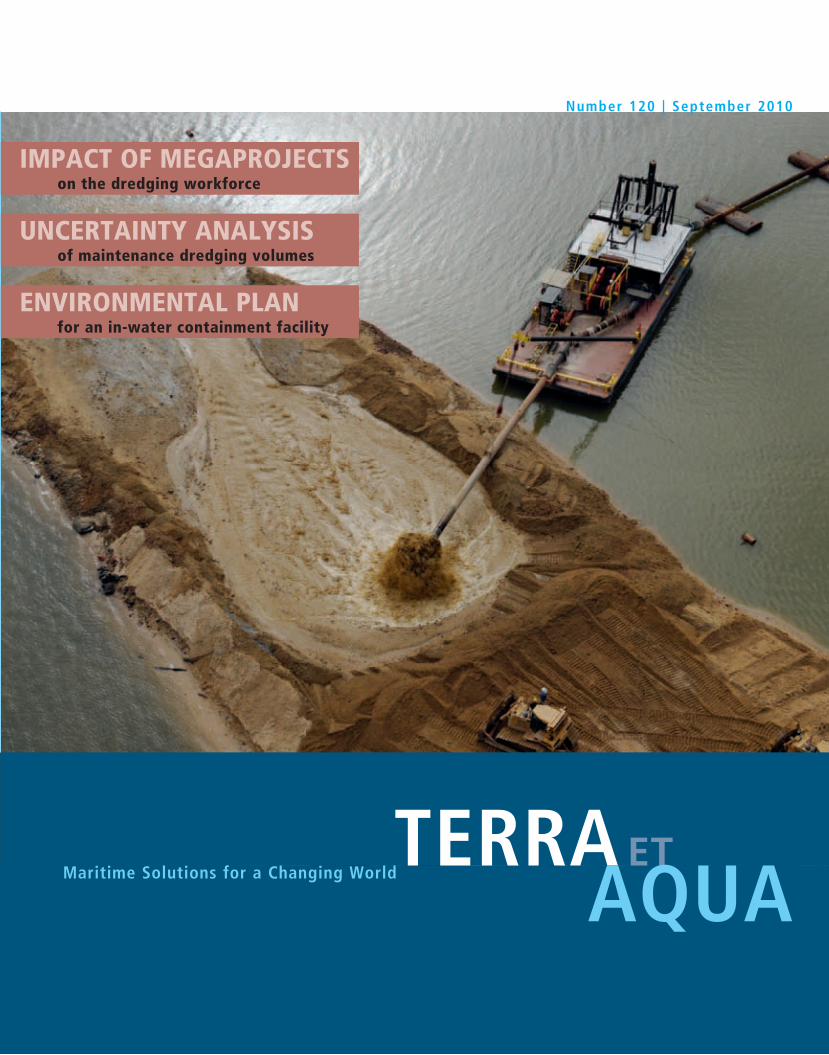
TERRA ET AQUA Maritime Solutions for a Changing World IMPACT OF MEGAPROJECTS on the dredging workforce UNCERTAINTY ANALYSIS of maintenance dredging volumes ENVIRONMENTAL PLAN for an in-water containment facility Number 120 | September 2010
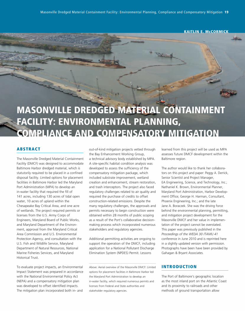
Baltimore Harbor, Maryland, urgently needed a dredged material containment facility (DMCF) as all previous areas were
closing in December 2009. With unusual speed, approvals and permits were received in 28 months and work could begin.
Shown here: An aerial view of the direct placement of hydraulically dredged onsite-borrow into the dike section at the
new Masonville DMCF.
TERRA ETAQUA
Guidelines for Authors
Terra et Aqua is a quarterly publication of the International Association of Dredging Companies,
emphasising “maritime solutions for a changing world”. It covers the fields of civil, hydraulic
and mechanical engineering including the technical, economic and environmental aspects
of dredging. Developments in the state of the art of the industry and other topics from the
industry with actual news value will be highlighted.
• As Terra et Aqua is an English language journal, articles must be submitted in English.
• Contributions will be considered primarily from authors who represent the various disciplines
of the dredging industry or professions, which are associated with dredging.
• Students and young professionals are encouraged to submit articles based on their research.
• Articles should be approximately 10-12 A4s. Photographs, graphics and illustrations are
encouraged. Original photographs should be submitted, as these provide the best quality.
Digital photographs should be of the highest resolution.
• Articles should be original and should not have appeared in other magazines or publications.
An exception is made for the proceedings of conferences which have a limited reading public.
• In the case of articles that have previously appeared in conference proceedings, permission
to reprint in Terra et Aqua will be requested.
• Authors are requested to provide in the “Introduction” an insight into the drivers (the Why)
behind the dredging project.
• By submitting an article, authors grant IADC permission to publish said article in both the
printed and digital version of Terra et Aqua without limitations and remunerations.
• All articles will be reviewed by the Editorial Advisory Committee (EAC). Publication of an
article is subject to approval by the EAC and no article will be published without approval
of the EAC.
MEMbERShip liST iADC 2010Through their regional branches or through representatives, members of IADC operate directly at all locations worldwide
AfricABoskalis International Egypt, Cairo, EgyptDredging and Reclamation Jan De Nul Ltd., Lagos, NigeriaDredging International Services Nigeria Ltd, Ikoyi Lagos, NigeriaNigerian Westminster Dredging and Marine Ltd., Lagos, NigeriaVan Oord Nigeria Ltd, Victoria Island, Nigeria
AsiABeijing Boskalis Dredging Technology Co. Ltd., Beijing, P.R. ChinaVan Oord (Shanghai) Dredging Co. Ltd, Shanghai, P.R. ChinaVan Oord Dredging and Marine Contractors bv Hong Kong Branch, Hong Kong, P.R. ChinaBoskalis Dredging India Pvt Ltd., Mumbai, IndiaInternational Seaport Dredging Private Ltd., New Delhi, IndiaJan De Nul Dredging India Pvt. Ltd., IndiaVan Oord India Pte Ltd, Mumbai, IndiaP.T. Boskalis International Indonesia, Jakarta, IndonesiaPT Penkonindo LLC, Jakarta, IndonesiaPenta-Ocean Construction Co. Ltd., Tokyo, JapanToa Corporation, Tokyo, JapanHyundai Engineering & Construction Co. Ltd., Seoul, KoreaVan Oord Dredging and Marine Contractors bv Korea Branch, Busan, Republic of KoreaVan Oord (Malaysia) Sdn Bhd, Selangor, MalaysiaVan Oord Dredging and Marine Contractors bv Philippines Branch, Manilla, PhilippinesBoskalis International Pte Ltd., SingaporeDredging International Asia Pacific (Pte) Ltd., SingaporeJan De Nul Singapore Pte. Ltd., SingaporeVan Oord Dredging and Marine Contractors bv Singapore Branch, SingaporeZinkcon Marine Singapore Pte. Ltd., SingaporeVan Oord Thai Ltd, Bangkok, Thailand
AusTrAliA + NEW ZEAlANDBoskalis Australia Pty, Ltd., Sydney, AustraliaDredeco Pty. Ltd., Brisbane, QLD, AustraliaVan Oord Australia Pty Ltd., Brisbane, QLD, AustraliaWA Shell Sands Pty Ltd, Perth, AustraliaNZ Dredging & General Works Ltd, Maunganui, New Zealand
EuropEBaggerwerken Decloedt & Zoon NV, Oostende, BelgiumDEME Building Materials NV (DBM), Zwijndrecht, BelgiumDredging International N.V., Zwijndrecht, BelgiumJan De Nul n.v., Hofstade/Aalst, BelgiumBoskalis Westminster Dredging & Contracting Ltd., CyprusBoskalis Westminster Middle East Ltd., Limassol, CyprusVan Oord Middle East Ltd, Nicosia, CyprusRohde Nielsen, Copenhagen, DenmarkTerramare Eesti OU, Tallinn, EstoniaTerramare Oy, Helsinki, FinlandAtlantique Dragage Sarl, St. Germain en Laye, FranceSociété de Dragage International ‘SDI’ SA, Lambersart, FranceSodraco International S.A.S., Lille, France Sodranord SARL, Le Blanc-Mesnil Cédex, FranceBrewaba Wasserbaugesellschaft Bremen mbH, Bremen, GermanyHeinrich Hirdes G.m.b.H., Hamburg, GermanyNordsee Nassbagger-und Tiefbau GmbH, Bremen, GermanyVan Oord Gibraltar Ltd, GibraltarIrish Dredging Company, Cork, IrelandVan Oord Ireland Ltd, Dublin, IrelandBoskalis Italia, Rome, Italy
Dravo SA, Italia, Amelia (TR), ItalySocieta Italiana Dragaggi SpA ‘SIDRA’, Rome, ItalyBaltic Marine Contractors SIA, Riga, LatviaDredging and Maritime Management s.a., Steinfort, LuxembourgDredging International (Luxembourg) SA, Luxembourg, LuxembourgTOA (LUX) S.A., Luxembourg, LuxembourgAannemingsbedrijf L. Paans & Zonen, Gorinchem, NetherlandsBaggermaatschappij Boskalis B.V., Papendrecht, NetherlandsBoskalis B.V., Rotterdam, NetherlandsBoskalis International B.V., Papendrecht, NetherlandsBoskalis Offshore bv, Papendrecht, NetherlandsDredging and Contracting Rotterdam b.v., Bergen op Zoom, NetherlandsMijnster zand- en grinthandel bv, Gorinchem, NetherlandsTideway B.V., Breda, NetherlandsVan Oord ACZ Marine Contractors bv, Rotterdam, NetherlandsVan Oord Nederland bv, Gorinchem, NetherlandsVan Oord nv, Rotterdam, NetherlandsVan Oord Offshore bv, Gorinchem, NetherlandsDragapor Dragagens de Portugal S.A., Alcochete, PortugalDravo SA, Lisbon, PortugalBallast Ham Dredging, St. Petersburg, RussiaDravo SA, Madrid, SpainFlota Proyectos Singulares S.A., Madrid, SpainSociedade Española de Dragados S.A., Madrid, SpainBoskalis Sweden AB, Gothenburg, SwedenDredging International (UK) Ltd., Weybridge, UKJan De Nul (UK) Ltd., Ascot, UKRock Fall Company Ltd, Aberdeen, UKVan Oord UK Ltd., Newbury, UKWestminster Dredging Co. Ltd., Fareham, UK
MiDDlE EAsTBoskalis Westminster Middle East Ltd., Manama, BahrainBoskalis Westminster (Oman) LLC, Muscat, OmanBoskalis Westminster Middle East, Doha, QatarMiddle East Dredging Company (MEDCO), Doha, QatarBoskalis Westminster Al Rushaid Co. Ltd., Al Khobar, Saudi ArabiaBoskalis Westminster M.E. Ltd., Abu Dhabi, U.A.E.Gulf Cobla (Limited Liability Company), Dubai, U.A.E.Jan De Nul Dredging Ltd. (Dubai Branch), Dubai, U.A.E.National Marine Dredging Company, Abu Dhabi, U.A.E.Van Oord Gulf FZE, Dubai, U.A.E.
ThE AMEricAsBoskalis International bv Sucural Argentina, Buenos Aires, ArgentinaCompañía Sud Americana de Dragados S.A, Buenos Aires, ArgentinaVan Oord ACZ Marine Contractors bv Argentina Branch, Buenos Aires, ArgentinaBallast Ham Dredging do Brazil Ltda, Rio de Janeiro, BrazilVan Oord Curaçao nv, Willemstad, CuraçaoDragamex SA de CV, Coatzacoalcos, MexicoDredging International Mexico SA de CV, Veracruz, MexicoMexicana de Dragados S.A. de C.V., Mexico City, MexicoCoastal and Inland Marine Services Inc., Bethania, PanamaDredging International de Panama SA, Panama Westminster Dredging Overseas, TrinidadStuyvesant Dredging Company, Louisiana, U.S.A.Boskalis International Uruguay S.A., Montevideo, UruguayDravensa C.A., Caracas, VenezuelaDredging International NV - Sucursal Venezuela, Caracas, Venezuela
Terra et Aqua is published quarterly by the IADC, The International Association
of Dredging Companies. The journal is available on request to individuals or
organisations with a professional interest in dredging and maritime infrastructure
projects including the development of ports and waterways, coastal protection,
land reclamation, offshore works, environmental remediation and habitat restoration.
The name Terra et Aqua is a registered trademark.
for a free subscription register at www.terra-et-aqua.com
Uncertainty Analysis of the Mud Infill Prediction of the OKLNG Approach Channel 15
the flow regime, the channel configuration
and wave action. Unfortunately no simple
equation exists that properly takes relevant
processes, such as floc formation and
break-up, into account and gives a reliable
prediction of the trapping efficiency of a
sediment-laden flow passing a channel.
More importantly, these processes are still
not well understood and the formulas always
require validation with field measurements.
Therefore numerical models such as DELFT 3D,
MIKE 21 and FINEL 2D are almost always used
to compute the trapping efficiency for
suspended sediment infill.
In this case, trapping efficiencies calculated
with FINEL 2D by Svasek Hydraulics and Royal
Haskoning (2008, Table 4.4) were used as
input for the infill computation.
This also points to another difficulty when
modelling scenario 2. A small part of the time,
infill is caused by mud layer infill and a
different trapping efficiency should be
applied.
A criterion to decide which of the two infill
mechanisms should be applied is required
additionally.
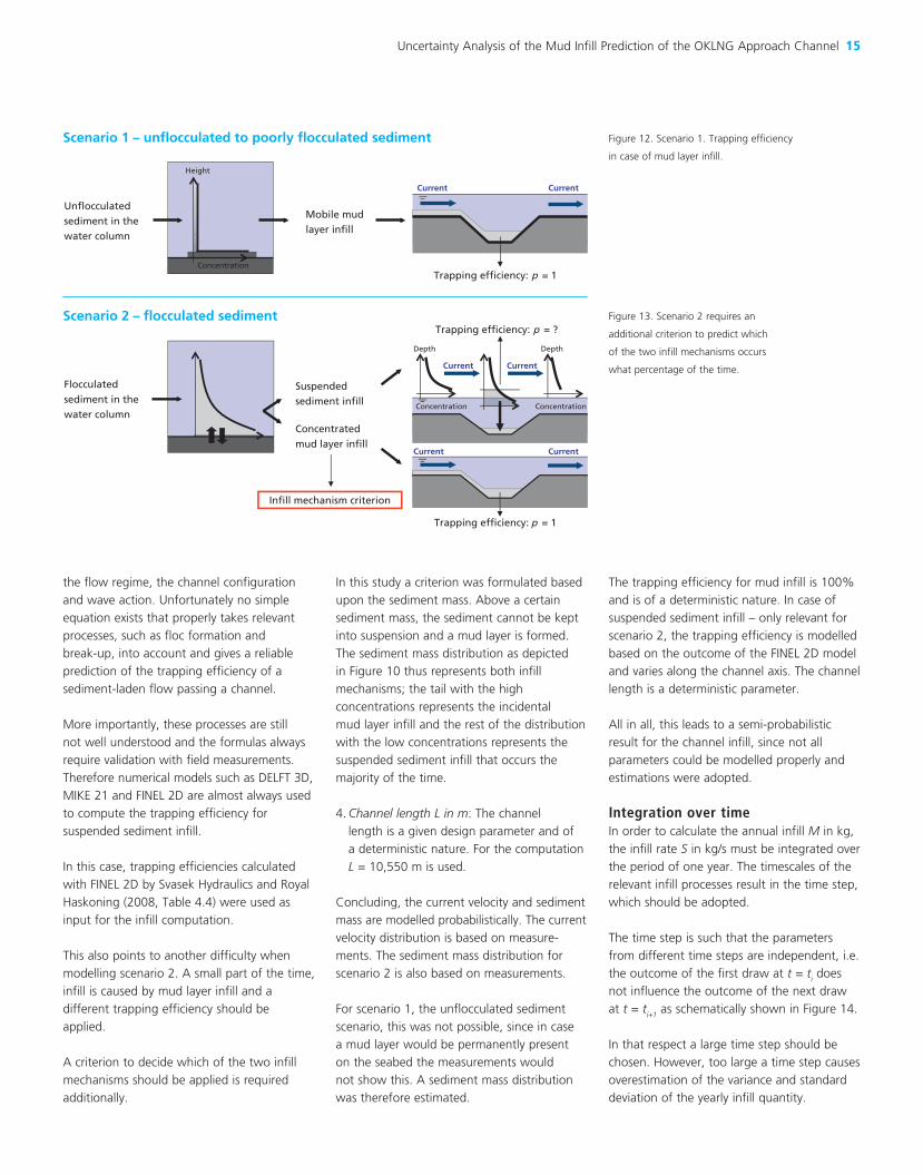
In this study a criterion was formulated based
upon the sediment mass. Above a certain
sediment mass, the sediment cannot be kept
into suspension and a mud layer is formed.
The sediment mass distribution as depicted
in Figure 10 thus represents both infill
mechanisms; the tail with the high
concentrations represents the incidental
mud layer infill and the rest of the distribution
with the low concentrations represents the
suspended sediment infill that occurs the
majority of the time.
4. Channel length L in m: The channel
length is a given design parameter and of
a deterministic nature. For the computation
L = 10,550 m is used.
Concluding, the current velocity and sediment mass are modelled probabilistically. The current
velocity distribution is based on measure-
ments. The sediment mass distribu tion for
scenario 2 is also based on measure ments.
For scenario 1, the unflocculated sediment
scenario, this was not possible, since in case
a mud layer would be permanently present
on the seabed the measurements would
not show this. A sedi ment mass distribution
was therefore estimated.
The trapping efficiency for mud infill is 100%
and is of a deterministic nature. In case of
suspended sediment infill – only relevant for
scenario 2, the trapping efficiency is modelled
based on the outcome of the FINEL 2D model
and varies along the channel axis. The channel
length is a deterministic parameter.
All in all, this leads to a semi-probabilistic
result for the channel infill, since not all
parameters could be modelled properly and
estimations were adopted.
Integration over timeIn order to calculate the annual infill M in kg,
the infill rate S in kg/s must be integrated over
the period of one year. The timescales of the
relevant infill processes result in the time step,
which should be adopted.
The time step is such that the parameters
from different time steps are independent, i.e.
the outcome of the first draw at t = ti does
not influence the outcome of the next draw
at t = ti+1
as schematically shown in Figure 14.
In that respect a large time step should be
chosen. However, too large a time step causes
overestimation of the variance and standard
deviation of the yearly infill quantity.
Scenario 1 – unflocculated to poorly flocculated sediment
Unflocculated
sediment in the
water column
Concentration
Height
Mobile mud
layer infill
Current Current
Trapping efficiency: p = 1
Figure 12. Scenario 1. Trapping efficiency
in case of mud layer infill.
Figure 13. Scenario 2 requires an
additional criterion to predict which
of the two infill mechanisms occurs
what percentage of the time.
Flocculated
sediment in the
water column
Scenario 2 – flocculated sediment
Suspended
sediment infill
Depth
Concentration
Depth
Concentration
Current Current
Current Current
Concentrated
mud layer infill
Trapping efficiency: p = 1
Trapping efficiency: p = ?
Infill mechanism criterion
16 Terra et Aqua | Number 120 | September 2010
The mean infill value does not change if the
number of time steps is increased, but the
standard deviation decreases. The standard
deviation of the yearly infill distribution
decreases with a factor √n when the number
of time steps n increases.
Ideally, the choice of the length of a
representative time step should be based
on an analysis of the correlation and the time
scales of the relevant physical processes.
Autocorrelation functions can be used to
determine this time step (Van Gelder, 2000).
In this study a pragmatic time step of one
week was adopted for each scenario, based
on the time scale for current reversals.
The assumption was that the input parameters
vary on a weekly basis, so the number of time
steps in one year is 52.
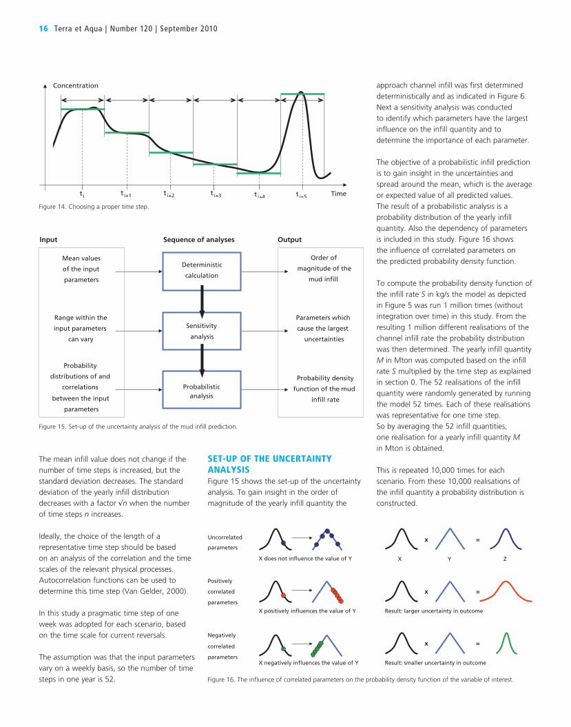
set-UP of tHe UnceRtAInty AnALysIsFigure 15 shows the set-up of the uncertainty
analysis. To gain insight in the order of
magnitude of the yearly infill quantity the
approach channel infill was first determined
deterministically and as indicated in Figure 6.
Next a sensitivity analysis was conducted
to identify which parameters have the largest
influence on the infill quantity and to
determine the importance of each parameter.
The objective of a probabilistic infill prediction
is to gain insight in the uncertainties and
spread around the mean, which is the average
or expected value of all predicted values.
The result of a probabilistic analysis is a
probability distribution of the yearly infill
quantity. Also the dependency of parameters
is included in this study. Figure 16 shows
the influence of correlated parameters on
the predicted probability density function.
To compute the probability density function of
the infill rate S in kg/s the model as depicted
in Figure 5 was run 1 million times (without
integration over time) in this study. From the
resulting 1 million different realisations of the
channel infill rate the probability distribution
was then determined. The yearly infill quantity
M in Mton was computed based on the infill
rate S multiplied by the time step as explained
in section 0. The 52 realisations of the infill
quantity were randomly generated by running
the model 52 times. Each of these realisations
was representative for one time step.
So by averaging the 52 infill quantities,
one realisation for a yearly infill quantity M
in Mton is obtained.
This is repeated 10,000 times for each
scenario. From these 10,000 realisations of
the infill quantity a probability distribution is
constructed.
Mean values
of the input
parameters
Deterministic
calculation
Order of
magnitude of the
mud infill
Range within the
input parameters
can vary
Sensitivity
analysis
Parameters which
cause the largest
uncertainties
Probability
distributions of and
correlations
between the input
parameters
Probabilisticanalysis
Probability density
function of the mud
infill rate
Input OutputSequence of analyses
Figure 15. Set-up of the uncertainty analysis of the mud infill prediction.
x =Uncorrelated
parameters
Positively
correlated
parameters
Negatively
correlated
parameters
x =
x =
Result: larger uncertainty in outcome
Result: smaller uncertainty in outcome
X does not influence the value of Y X Y Z
X positively influences the value of Y
X negatively influences the value of Y
Figure 16. The influence of correlated parameters on the probability density function of the variable of interest.
t i+5t i+2t i
Concentration
ti+1 t i+3 t i+4 Time
Figure 14. Choosing a proper time step.
Uncertainty Analysis of the Mud Infill Prediction of the OKLNG Approach Channel 17
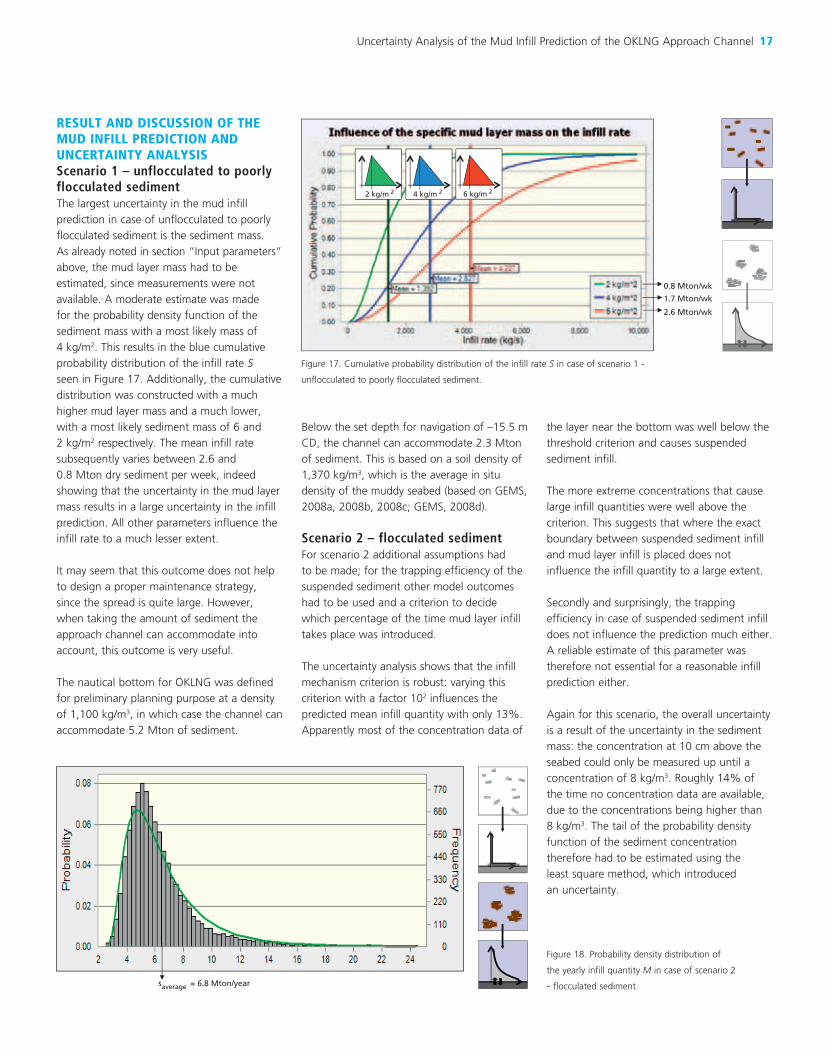
ResULt AnD DIscUssIon of tHe MUD InfILL PReDIctIon AnD UnceRtAInty AnALysIsScenario 1 – unflocculated to poorly flocculated sedimentThe largest uncertainty in the mud infill
prediction in case of unflocculated to poorly
flocculated sediment is the sediment mass.
As already noted in section “Input parameters”
above, the mud layer mass had to be
estimated, since measurements were not
available. A moderate estimate was made
for the probability density function of the
sediment mass with a most likely mass of
4 kg/m2. This results in the blue cumulative
probability distribution of the infill rate S
seen in Figure 17. Additionally, the cumulative
distribution was constructed with a much
higher mud layer mass and a much lower,
with a most likely sediment mass of 6 and
2 kg/m2 respectively. The mean infill rate
subsequently varies between 2.6 and
0.8 Mton dry sediment per week, indeed
showing that the uncertainty in the mud layer
mass results in a large uncertainty in the infill
prediction. All other parameters influence the
infill rate to a much lesser extent.
It may seem that this outcome does not help
to design a proper maintenance strategy,
since the spread is quite large. However,
when taking the amount of sediment the
approach channel can accommodate into
account, this outcome is very useful.
The nautical bottom for OKLNG was defined
for preliminary planning purpose at a density
of 1,100 kg/m3, in which case the channel can
accommodate 5.2 Mton of sediment.
Below the set depth for navigation of –15.5 m
CD, the channel can accommodate 2.3 Mton
of sediment. This is based on a soil density of
1,370 kg/m3, which is the average in situ
density of the muddy seabed (based on GEMS,
2008a, 2008b, 2008c; GEMS, 2008d).
Scenario 2 – flocculated sedimentFor scenario 2 additional assumptions had
to be made; for the trapping efficiency of the
suspended sediment other model outcomes
had to be used and a criterion to decide
which percentage of the time mud layer infill
takes place was introduced.
The uncertainty analysis shows that the infill
mechanism criterion is robust: varying this
criterion with a factor 102 influences the
predicted mean infill quantity with only 13%.
Apparently most of the concentration data of
the layer near the bottom was well below the
threshold criterion and causes suspended
sediment infill.
The more extreme concentrations that cause
large infill quantities were well above the
criterion. This suggests that where the exact
boundary between suspended sediment infill
and mud layer infill is placed does not
influence the infill quantity to a large extent.
Secondly and surprisingly, the trapping
efficiency in case of suspended sediment infill
does not influence the prediction much either.
A reliable estimate of this parameter was
therefore not essential for a reasonable infill
prediction either.
Again for this scenario, the overall uncertainty
is a result of the uncertainty in the sediment
mass: the concentration at 10 cm above the
seabed could only be measured up until a
concentration of 8 kg/m3. Roughly 14% of
the time no concentration data are available,
due to the concentrations being higher than
8 kg/m3. The tail of the probability density
function of the sediment concentration
therefore had to be estimated using the
least square method, which introduced
an uncertainty.
1.7 Mton/wk
0.8 Mton/wk
2.6 Mton/wk
6 kg/m 24 kg/m 22 kg/m 2
Figure 17. Cumulative probability distribution of the infill rate S in case of scenario 1 -
unflocculated to poorly flocculated sediment.
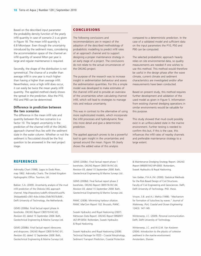
saverage = 6.8 Mton/year
Figure 18. Probability density distribution of
the yearly infill quantity M in case of scenario 2
- flocculated sediment.
18 Terra et Aqua | Number 120 | September 2010
Based on the described input parameter
the probability density function of the yearly
infill quantity in case of scenario 2 is as given
in Figure 18. The mean infill quantity is
6.8 Mton/year. Even though the uncertainty
introduced by the sediment mass, considering
the accommodation space of the channel an
infill quantity of several Mton per year is
large and regular maintenance is required.
Secondly, the shape of the distribution is not
symmetrical. The chance of a smaller than
average infill in one year is much higher
than having a higher than average infill.
Nevertheless, once a high infill does occur,
it can easily be twice the mean yearly infill
quantity. The applied method clearly shows
the spread in the prediction. Also the P10,
P50 and P90 can be determined.
Difference in prediction between the two scenariosThe difference in the mean infill rate and
quantity between the two scenarios is a
factor 10. The largest uncertainty in the
prediction of the channel infill of the OKLNG
approach channel thus lies with the sediment
state in the water column. Whether or not the
sediment is flocculated should be the first
question to be answered in the next project
stage.
CONCLUSIONS
The following conclusions and
recommendations are in respect of the
adoption of the described methodology of
probabilistic modelling to predict infill rates
of an approach channel and to support
designing a proper maintenance strategy in
an early stage of a project. The conclusions
do not relate to the actual circumstances of
the OKLNG project.
The purpose of the research was to increase
insight in sedimentation behaviour and assess
the sedimentation quantities. For this a simple
model was developed to make estimates of
the channel infill and to provide an overview
of the uncertainties when calculating channel
infill, which will lead to strategies to manage
risks and reduce uncertainty.
This was in contrast to the alternative of using
more sophisticated models, which incorporate
the infill processes and hydrodynamic flow
into more detail and give a deterministic
prediction.
The applied approach proves to be a powerful
tool to gain insight in the uncertainties and
spread around the mean. Figure 18 clearly
shows the added value of this analysis
compared to a deterministic prediction. In the
case of a validated model and sufficient data
on the input parameters the P10, P50 and
P90 can be computed.
The selected probabilistic approach heavily
relies on site environmental data, so quality
measurements are needed if one wishes to
use this method. This method would therefore
be useful in the design phase after the wave
climate, current climate and sediment
characteristics are investigated and/or after
measurements have been conducted.
Based on present study, this method requires
further development and validation of the
used model as given in Figure 5. Information
from existing channel dredging operations in
similar environments would be valuable for
this purpose.
This study showed that mud could possibly
exist in an unflocculated state in the marine
environment. Further testing is needed to
confirm this but, if this is the case, this
influences the infill rates of nearby channels
and preferable maintenance strategy to a
large extent.
REFERENCES
Admiralty Chart (1998). Lagos to Dodo River,
map 1862. Admiralty Charts. The United Kingdom
Hydrographic Office. Taunton, UK.
Bakker, S.A. (2009). Uncertainty analysis of the mud
Masonville Dredged Material Containment Facility: Environmental Planning, Compliance and Compensatory Mitigation 23
oxyrinchus). While this was a species of
concern for NMFS, there was no regulatory
authority to require any mitigation measures
to protect this species.
FWS’s response noted the presence of the
federally listed bald eagle (Haliaeetus leucocephalus) within a quarter of a mile
of the project footprint within adjacent
Masonville Cove. No other federally listed
species within the jurisdiction of the FWS
were documented within the vicinity of the
proposed project.
MDNR identified two state listed bird species
of concern that were not documented within
the project area. However, the range for these
species included the project area. If the
habitat for these species were present within
the project area, then further measures to
protect these species, such as time-of-year
restrictions would be recommended.
These species were: hooded merganser
(Lophodytes cucullatus) and common
moorhen (Gallinula chloropus). MDNR also
noted in their letter that the area adjacent
to the proposed DMCF is a known historic
waterfowl concentration area.
SHPO responded and issued their concurrence
with the findings of the cultural resources
survey completed by MPA’s contractors.
No further coordination on cultural resources
was required.
Coordination was also completed with NMFS
related to essential fish habitat (EFH), which
is designated under the Magnuson Stevens
Fishery Management Act (MSFMA). The
MSFMA (16 USC 1801 et seq. Public Law
104-208) establishes the Secretary of
Commerce and Fishery Management Council
authority and responsibilities for the protection
of EFH. The Act specifies that each federal
agency shall consult with the Secretary with
respect to any action authorized, funded, or
undertaken, or proposed to be authorized,
funded, or undertaken by such agency that
may adversely affect any EFH identified under
this act. EFH is defined as “those waters and
substrate necessary to fish for spawning,
breeding, feeding, or growth to maturity.”
MPA’s coordination with NMFS regional
office identified two EFH species likely to
occur within the project area: adult and
juvenile summer flounder (Paralicthys dentatus) and adult and juvenile bluefish (Pomatomus saltatrix).
DRAft enVIRonMentAL IMPAct stAteMentAfter identifying all resource concerns, the
MPA and its contractors, hereafter referred to
as the Masonville Project Delivery Team (PDT)
began preparation of the DEIS in consultation
with the USACE. The USACE was determined
to be the lead federal agency for the project
and the EIS was completed to meet the
USACE regulatory requirement for an EIS
under the NEPA. As previously stated, the EIS
was required because the project required
a federal permit and had the potential for
significant adverse impacts to aquatic
resources. Preparation of the DEIS identified
resources within the project vicinity of
particular concern. Some of these concerns
were identified by other regulatory agencies
through the scoping and consultation
processes, such federally listed species; others
were identified by analyzing site-specific data.
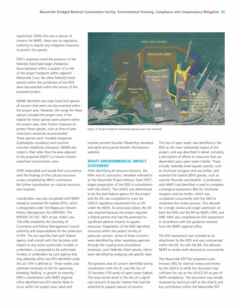
The greatest area of concern identified during
coordination with the JE, was the loss of
53 hectares (130 acres) of open water habitat.
This area would result in the loss of a signifi-
cant amount of aquatic habitat that had the
potential to support species of concern.
This loss of open water was identified in the
DEIS as the most substantial impact of the
project, and was described in detail, including
a description of effects to resources that are
dependent upon open water habitat. These
include, federally listed aquatic species, such
as shortnose sturgeon and sea turtles, and
essential fish habitat (EFH) species, such as
summer flounder and bluefish. Coordination
with NMFS had identified a need to complete
a biological assessment (BA) for shortnose
sturgeon and sea turtles, which was
completed concurrently with the DEIS to
streamline the review process. This allowed
for a single review and single submission of
both the DEIS and the BA by NMFS, FWS, and
DNR. MPA also completed an EFH assessment,
in accordance with the guidance received
from the NMFS regional office.
The EFH assessment was included as an
attachment to the DEIS and was summarized
within the EIS. As with the BA, this allowed
NMFS to review both documents concurrently.
The Masonville PDT first prepared a pre-
liminary DEIS for internal review and review
by the USACE to verify the document was
sufficient for use as the USACE EIS as part of
NEPA compliance. The document was initially
reviewed by technical staff at the USACE and
key contributors within the Masonville PDT.
Figure 3. Project footprint indicating disposal area and wetlands.
24 Terra et Aqua | Number 120 | September 2010
All comments were consolidated and
integrated into the document, prior to formal
submission to the USACE for supervisor and
legal review. At this time, a meeting between
the USACE and MPA occurred and the USACE
determined that it would be prudent to
incorporate MDE as an informal cooperating
agency on the EIS, because of its jurisdiction
over the fill of open water and wetlands.
Both agencies were considering the potentially
significant impacts of the proposed project
relative to the permit request and could most
efficiently work together by partnering in the
development of the EIS and determination
of project impacts and required mitigation.
Concurrently with the development of the
DEIS with USACE and MDE, MPA coordinated
with the JE regarding potential mitigation
requirements associated with the MPA’s
preferred project alternative. This mitigation
package, discussed further in the following
subsections, was incorporated into the
mitigation and impacts sections of the DEIS,
to comprehensively document the project
impacts and mitigation. MDE and USACE both
had regulatory authority to require the MPA
to offset document impacts associated with
the fill of wetlands and open water.
Additional mitigation was required for
compliance with Maryland’s Critical Area Act,
which is discussed further below.
After integrating MDE and USACE’s predicted
mitigation needs into the DEIS, MPA provided
a revised preliminary DEIS to both agencies for
their review and comment. The initial review
process for the DEIS was time consuming,
with many rounds of review and comment.
During this review and comment process,
MPA was cognizant of the need to expedite
the internal review of the DEIS, so that the
overall project schedule could be met.
After addressing all MDE and USACE
comments on the preliminary DEIS, MPA,
USACE, and MDE implemented a plan to
allow review of the preliminary DEIS by other
state and federal agencies prior to issuance
of the DEIS to the public. MPA desired to
proactively address agency concerns early in
the process, by identifying agency concerns
upfront, which would allow MPA additional
time to address and respond those concerns.
Any minor comments received as part of the
preliminary DEIS review were addressed prior
to the issuance of the DEIS. More substantive
comments that could not be resolved prior
to issuance of the DEIS, were resolved during
the public comment period. By having agency
comments prior to the issuance of the DIES,
MPA gained the public comment period as
time to work on a resolution to those
comments rather than awaiting comments.
The DEIS was issued by the USACE in May
2006, which initiated the public comment
period for the project.
PUBLIc coMMent PeRIoD AnD HeARInGsMPA worked with MDE and USACE to
schedule public hearings on the proposed
project in advance of the issuance of the DEIS.
These public hearings were not required, but
could be requested by the public. If a member
of the public requests a public hearing of
MDE or USACE during the public comment
period, then a hearing must be held. To avoid
potential delays associated with scheduling
a hearing that would occur after the closure
of the comment period, a public hearing was
planned to occur during the public comment
period. If the hearings were not planned in
advance, then the schedule could have been
delayed for weeks or months as a result of the
need for additional public hearings after the
comment period closed. The public meeting
was held in the community adjacent to the
Masonville DMCF project site during evening
hours to be convenient to area residents.
Public comments on the DEIS were noted
by the USACE, MDE, and MPA and were
addressed, as appropriate. Comments were
made in support of the Masonville DMCF
project and in support of the Masonville Cove
restoration component. There were comments
from area residents requesting changes,
modifications, or additions to the proposed
compensatory mitigation package and some
requests for additional detail about the
potential impacts of the DMCF to specific
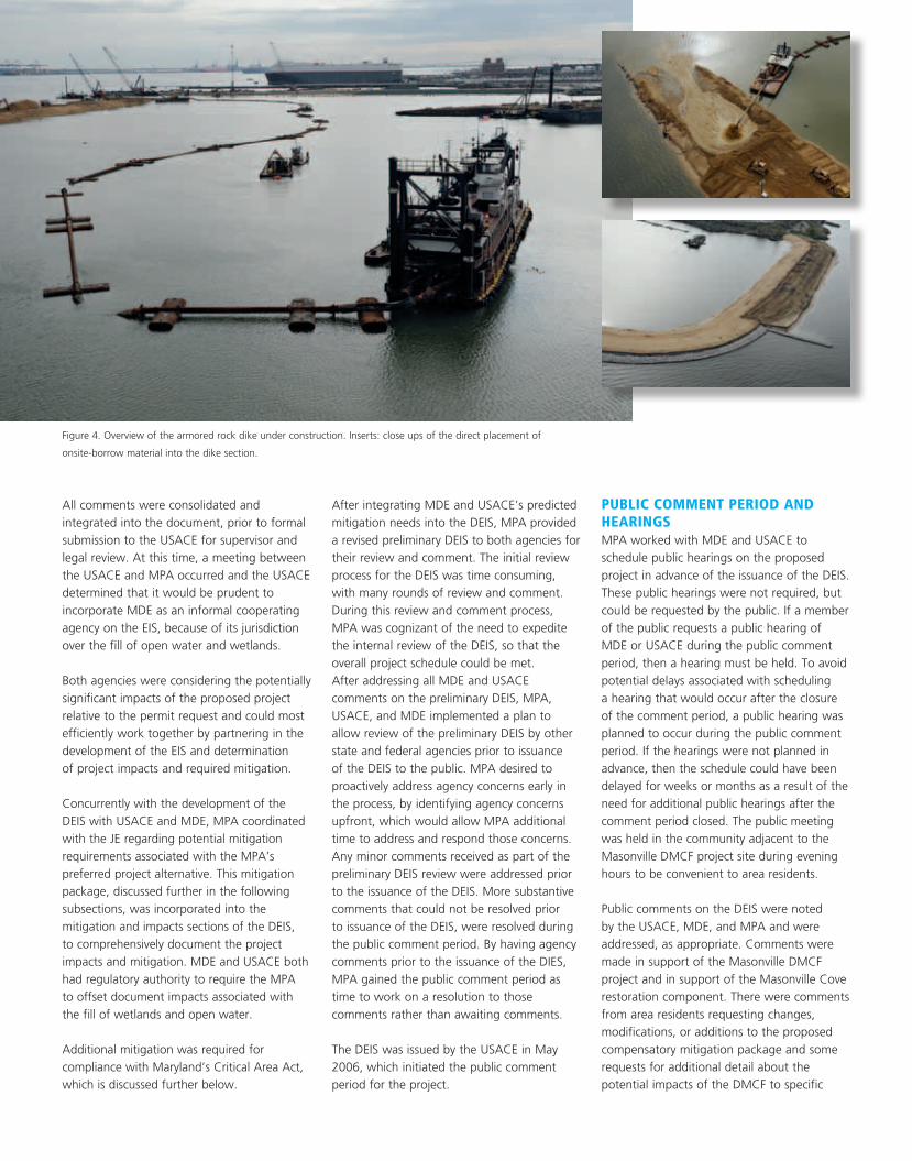
Figure 4. Overview of the armored rock dike under construction. Inserts: close ups of the direct placement of
onsite-borrow material into the dike section.
Masonville Dredged Material Containment Facility: Environmental Planning, Compliance and Compensatory Mitigation 25
resources, such as changes to Patapsco River
hydrology and hydrodynamics. Most of the
comments received were from private citizens
and community organizations. Other
commenters included state and federal
agencies issuing their formal comments on the
project, a representative from a private marine
terminal, and local non-profit organizations,
such as the Living Classrooms Foundation and
the National Aquarium in Baltimore.
All comments were recorded and integrated
into a comment and response table, for
integration in the FEIS.
cHAnGes to tHe PRoJect DesIGn AfteR fInALIZInG tHe DeIsDuring the public comment period for the
DEIS, a new alternative to the existing MPA
preferred alternative was identified by MPA.
The new alternative linked the Masonville
DMCF project to the Seagirt-Dundalk Marine
Terminal Deepening and Widening project
(Seagirt Project).The Seagirt project was
expected to generate approximately
380,000 cubic meters (cm) (500,000 cubic
yards (cy)) of dredged material consisting of
sand and gravel and potentially suitable for
construction of the Masonville DMCF. The
linking of the projects eliminated the need to
purchase construction material for the DMCF
and the need to place that material from the
new work project at Seagirt-Dundalk Marine
Terminals in a confined placement facility.
The linking of the projects provided
a significant cost savings to MPA and also
produced environmental benefits associated
with regional air quality by reducing the
transport and offloading emissions associated
with the Seagirt project and by reducing the
need to transport clean construction material
for Masonville from an upland location.
This new alternative changed the impacts and
alternatives identified in the DEIS and resulted
in the need to either reissue the DEIS or issue a
supplement to the DEIS. To lose as little time as
possible from the project schedule, while still
gaining the cost savings associated with the
new Seagirt alternative, MPA prepared
a supplement to the DEIS (supplement) that
described the new alternative and its potential
impacts. MPA timed the release of the
supplement to be the same date as the public
hearing for the DEIS. USACE, MDE, and MPA
also determined that it would be prudent to
schedule a public hearing related to the new
alternative during the required public comment
period for the supplement. This required MPA,
USACE, and MDE to have the supplement
prepared more than one week prior to the
public meeting, so that the notice of availability
for the supplement could be published prior to
the hearing. The USACE and MPA arrived at
the public hearing with copies of the
supplement, information on the upcoming
public hearing, and posters and informational
material describing the new alternative. All
participants at the DEIS hearing were invited to
attend the public hearing on the supplement.
Only four individuals spoke at the second
public hearing. These individuals were residents
of the surrounding communities and included
representatives of the community groups.
These individuals raised concerns about crime
and safety at the site, oversight of the facility,
viewsheds in the project vicinity, and public
access of the Masonville Cove restoration
area. No comments were made opposing the
new project design and the public comment
period officially closed at the end of the
second public hearing.
AIR IMPActs – feDeRAL confoRMIty DeteRMInAtIonThe U.S. Environmental Protection Agency
(USEPA) has set National Ambient Air Quality
Standards (NAAQS) for six pollutants: ozone,
carbon monoxide, nitrogen dioxide, sulfur
dioxide, particulate matter, and lead. Any area
where a pollutant does not meet the air
quality standards set by the USEPA is
considered to be in non-attainment.
Non-attainment categories for ozone range
from sub marginal to extreme. It was deter-
mined the proposed project was in a region in
moderate non-attainment for ozone standard
and in non-attainment particulate matter 2.5
(USEPA 2010). The entire State of Maryland is
part of the Northeast Ozone Transport Region
(OTR), which was established in the 1990
Clean Air Act Amendments in recognition
of the long-standing ozone non-attainment
problems in the northeast.
Figure 5. Construction of the cofferdam
portion of the Masonville Dredged
Material Containment Facility.
26 Terra et Aqua | Number 120 | September 2010
Screening-level calculations of project
emissions were completed and compared
to de minimis thresholds as identified under
the authority of the federal conformity
provisions of the Clean Air Act. If the total of
direct and indirect emissions from a proposed
federal action in a non-attainment area are
below the de minimis thresholds specified in
40 CFR 93.153(b)(1) and the total emissions
are not “regionally significant,” comprising
10 percent or more of the region’s total
emissions of that pollutant, as specified in
40 CFR 93.153(i), the Federal Action is exempt
from the requirements of the general
conformity provision. Because these screening
calculations indicated that the project would
exceed the de minimis thresholds, a general
conformity analysis was completed for the
project. The general conformity provision
requires mitigation to be completed for all
project emissions of a pollutant, if the project
exceeds the de minimis thresholds for that
pollutant or precursor. The Masonville DMCF
project emissions of NOx exceeded the thres-
holds and required mitigation to offset those
emissions. MPA and its contractors worked
closely with MDE and USEPA to identify
credits to offset the impacts of the proposed
project. NOx credits were leased from another
project that would not be releasing its full
allocation of emissions. This was a unique,
one-time arrangement with MDE and USEPA.
MDE and USEPA stated that in future, MPA
would be required to develop emissions
offsets for its air quality impacts.
The federal conformity analysis was prepared
and extensive negotiations took place
between MDE, USEPA, and the USACE
regarding the calculations of impacts and
the measures identified to offset those
impacts. Because these determinations are
made so infrequently, it was unclear at first
which federal agency was responsible for
issuing the required federal conformity
determination. Though initially it was thought
that this determination would be made by the
USEPA, it was eventually decided that the lead
federal agency for the project (USACE) was
responsible for issuing the determination.
MPA prepared the conformity analysis and
worked with MDE, USEPA, and USACE to gain
concurrence from all three agencies for the
project. USACE used MPA’s conformity analysis
to prepare a draft conformity determination.
Because the MPA and USACE did not want to
delay the issuance of the DEIS, it was deter-
mined that the federal conformity determina-
tion would be finalized during the public
comment period and would be incorporated,
as draft, into the upcoming final environmental
impact statement (FEIS). This ensured that the
project schedule was not delayed as a result of
the federal conformity process.
WAteR AnD WetLAnD IMPActs – MItIGAtIon sUffIcIency Concurrent with the development of the DEIS,
SEIS, and preliminary phases of the FEIS, MPA
continued to meet with the JE to develop a
sufficient compensatory mitigation package
to offset the impacts of the proposed project.
USACE required MPA to provide a detailed
alternatives analysis of all efforts to avoid and
minimize impacts in the DEIS and supplement.
After impacts were avoided and minimized to
the extent possible, the overall project impacts
were considered. MPA solicited recommen-
dations from state and federal resource
agencies, Baltimore City, and other participants
on the JE. The mitigation projects focused on
the restoration of the adjacent Masonville
Cove, but also incorporated offsite and out-of-
kind mitigation projects. Because of many
out-of-kind or unusual mitigation components
incorporated into the project, the JE and
USACE required a mechanism to determine the
overall sufficiency of the mitigation package to
offset the total project impacts.
In order to demonstrate that the proposed
mitigation options would replace the open-
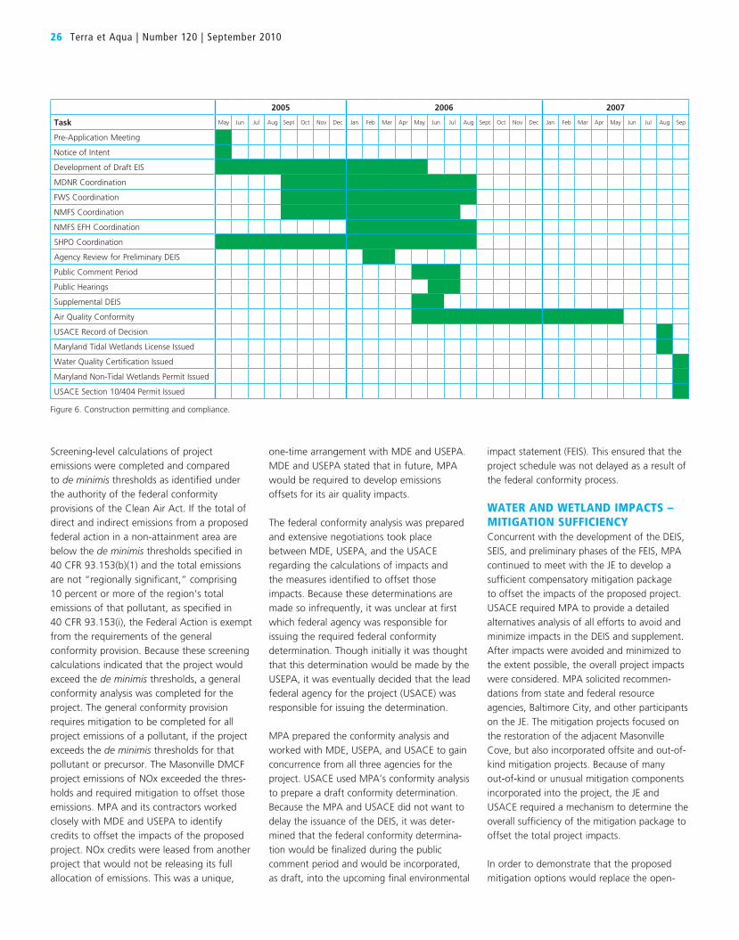
Figure 6. Construction permitting and compliance.
2005 2006 2007
Task May Jun Jul Aug Sept Oct Nov Dec Jan Feb Mar Apr May Jun Jul Aug Sept Oct Nov Dec Jan Feb Mar Apr May Jun Jul Aug Sep
Pre-Application Meeting
Notice of Intent
Development of Draft EIS
MDNR Coordination
FWS Coordination
NMFS Coordination
NMFS EFH Coordination
SHPO Coordination
Agency Review for Preliminary DEIS
Public Comment Period
Public Hearings
Supplemental DEIS
Air Quality Conformity
USACE Record of Decision
Maryland Tidal Wetlands License Issued
Water Quality Certification Issued
Maryland Non-Tidal Wetlands Permit Issued
USACE Section 10/404 Permit Issued
Masonville Dredged Material Containment Facility: Environmental Planning, Compliance and Compensatory Mitigation 27
water habitat functions lost by the develop-
ment of the proposed project, a project-
specific Habitat Condition Analysis (HCA) was
developed based on the National Oceanic and
Atmospheric Administration (NOAA) Habitat
Equivalency Analysis (HEA) approach. The HEA
approach assesses the values and functions
lost by environmental perturbations and
gained through mitigative measures.
The project-specific HCA involved a multi-
metric evaluation of the loss of functions as a
result of project impacts and functions gained
by implementation of the mitigation package.
The condition factors derived for the analysis
(Table III) came from commonly used,
regionally appropriate and broadly accepted
measures of environmental quality, such as
sediment quality criteria and the Chesapeake
Bay Benthic Index of Biotic Integrity. These
factors were reviewed by the regional Bay
Enhancement Working Group and the JE.
A consensus building approach was used
to gain support for the HCA process from
regional experts and project stakeholders.
As part of the evaluation, initial and final
condition factors were assigned for the project
area and the proposed mitigation options.
The difference between the initial and final
conditions of the project was scaled by the
acreage affected to determine the required
mitigation to offset project impacts. The same
calculation was then completed for each of
the components of the mitigation package
based on pre- and post-mitigation activities.
The gain in habitat functions as a result of
mitigation components was balanced against
the calculated loss (Table IV).
Community enhancements and other
environmental benefits associated with the
proposed project were also evaluated using
the HCA but were not included in the balance
sheet for mitigation of aquatic impacts.
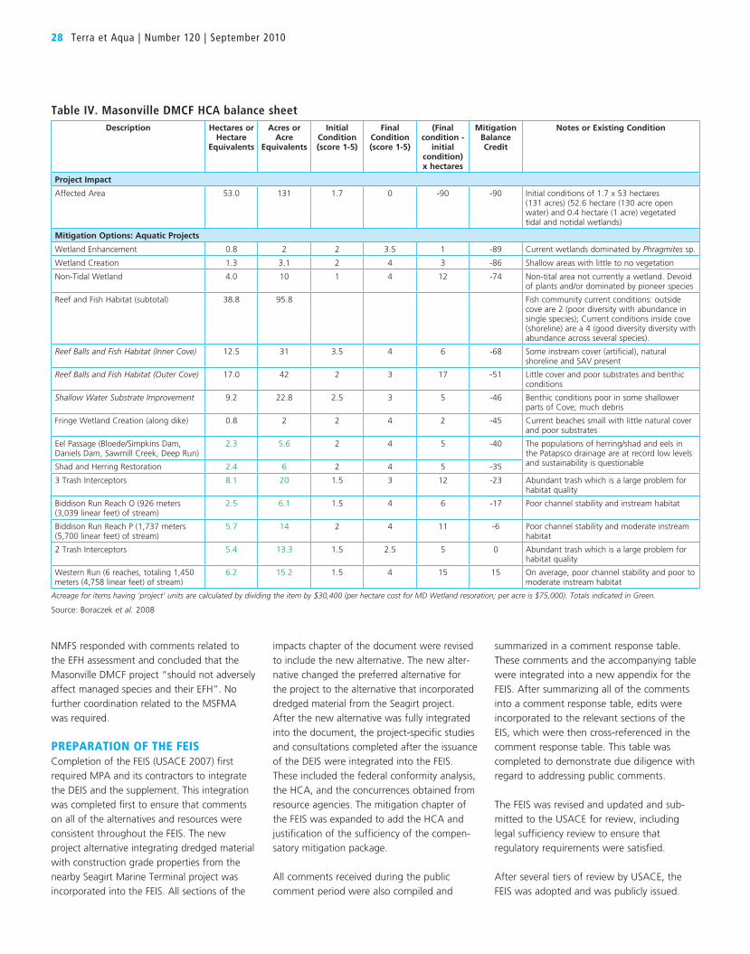
The HCA estimated that the mitigation
package would generate approximately
15 mitigation credits in excess of those
needed to compensate for the loss of open
water and wetlands. The analysis and results
were reviewed by the BEWG and JE and
demonstrated that the lost habitat functions
would be replaced within the watershed by
the proposed mitigation package. The HCA
was then incorporated into the FEIS to
demonstrate the sufficiency of the mitigation
package.
concLUsIon of consULtAtIonsDuring the public comment period, comments
were received from MHT, MDNR, NMFS, and
the U.S. Department of the Interior (on behalf
of FWS). MHT’s comment resulted in the
conclusion of Section 106 with no additional
comments beyond the determination that the
proposed project would not adversely affect
historic resources. MDNR noted that it would
not request TOY restrictions for the bald eagle,
but that it would request TOY restrictions to
protect spawning anadromous fish. No other
substantial comments were made about the
protection of habitat or species.
NMFS responded with a letter stating its
concurrence with the determination that the
Masonville DMCF project was unlikely to
adversely affect listed sea turtles or shortnose
sturgeon, but requested additional consulta-
tion on large whale species when the end use
of the DMCF site is developed. No further
consul tation was required for the construction
and operation of the Masonville DMCF.
DOI responded on half of FWS and had no
further comments specific to listed species or
habitat under the jurisdiction of FWS.
No further consultation was required with
FWS. The Chesapeake Bay Field Office of
Table III. Condition factors used in the HCACondition POOR (Eutrophic backwater) IDEAL (Barren Island)
Indicator or Feature 1 2 3 4 5
Chesapeake Bay Index of Biological Integrity (B-IBI)
Serverly degraded (poor abundance and diversity)
Degraded Fair (meets restoration goals)
Good Excellent (good diversity; stable community)
Fish (community) Little or no fish Poor diversity; abundance in one species
Moderate diversity and abundance
Good diversity; abundances across several species
High diversity and good abundances in alle seasons
Fish (population) Populations not sustainable; on verge of extirpation
Population marginally sustainable; poor recruit-ment relative to available habitat
Population struggling with wide variations in recruit-ment success
Population strong; recruit-ment successful in most years
Population fully sustainable and at full carrying capacity for available habitat
Contaminants Many exceed effects range median (ERM); some more than two times
Several > ERM; many > probable effects level (PEL) or ERM-Q
Some exceed PEL of ERM-Q; many greater than TEL
Several greater than threshold effects level (TEL); few other exceedances
Few or none > TEL
Aquatic Habitat (estuarine) No cover; bulkheaded; poor water quality and forage
Little cover; low dissolved oxygen (DO) seasonnally; degraded forage
Moderate cover; some submerged aquatic vegeta-tion (SAV); DO usually sup-portive; adequate forage
Good cover; soft shorelines; SAV present; good DO; stable forage
Diverse cover; stable SAV; good DO; abundant forage in alle seasons
Aquatic Habitat (stream) Highly entrenched; very low width to depth ratio; low sinuosity; riffles highly embedded; poor instream cover and benthic habitat
No entrenchment, width to depth ratio very high; high senuosity; little riffle embed-dedness; excellent instream cover and benthic habitat
Wetland and Riparian vegetation
Dominated by pioeer or invasive species; lots of human debris
Dominated by stable balan-ced communities of native species; little trash of debris
Note: To the extent possible, these definitions follow standard ecological measures for sediment quality, water quality, B-IBI, etc.The general approach is a multi-metric scoring technique following the IBI work of Karr and others.The benthic, stream and estuarine habitat and fisheries community definations are derived from various published multi-metric approaches.
Source: Boraczek et al. 2008
28 Terra et Aqua | Number 120 | September 2010
NMFS responded with comments related to
the EFH assessment and concluded that the
Masonville DMCF project “should not adversely
affect managed species and their EFH”. No
further coordination related to the MSFMA
was required.
PRePARAtIon of tHe feIsCompletion of the FEIS (USACE 2007) first
required MPA and its contractors to integrate
the DEIS and the supplement. This integration
was completed first to ensure that comments
on all of the alternatives and resources were
consistent throughout the FEIS. The new
project alternative integrating dredged material
with construction grade properties from the
nearby Seagirt Marine Terminal project was
incorporated into the FEIS. All sections of the
impacts chapter of the document were revised
to include the new alternative. The new alter-
native changed the preferred alternative for
the project to the alternative that incorpo rated
dredged material from the Seagirt project. After the new alternative was fully integrated
into the document, the project-specific studies
and consultations completed after the issuance
of the DEIS were integrated into the FEIS.
These included the federal conformity analysis,
the HCA, and the concurrences obtained from
resource agencies. The mitigation chapter of
the FEIS was expanded to add the HCA and
justification of the sufficiency of the compen-
satory mitigation package.
All comments received during the public
comment period were also compiled and
summarized in a comment response table.
These comments and the accompanying table
were integrated into a new appendix for the
FEIS. After summarizing all of the comments
into a comment response table, edits were
incorporated to the relevant sections of the
EIS, which were then cross-referenced in the
comment response table. This table was
completed to demonstrate due diligence with
regard to addressing public comments.
The FEIS was revised and updated and sub-
mitted to the USACE for review, including
legal sufficiency review to ensure that
regulatory requirements were satisfied.
After several tiers of review by USACE, the
FEIS was adopted and was publicly issued.
Table IV. Masonville DMCF HCA balance sheetDescription Hectares or
Hectare Equivalents
Acres or Acre
Equivalents
Initial Condition (score 1-5)
Final Condition (score 1-5)
(Final condition -
initial condition) x hectares
Mitigation Balance Credit
Notes or Existing Condition
Project Impact
Affected Area 53.0 131 1.7 0 -90 -90 Initial conditions of 1.7 x 53 hectares (131 acres) (52.6 hectare (130 acre open water) and 0.4 hectare (1 acre) vegetated tidal and notidal wetlands)
Mitigation Options: Aquatic Projects
Wetland Enhancement 0.8 2 2 3.5 1 -89 Current wetlands dominated by Phragmites sp.
Wetland Creation 1.3 3.1 2 4 3 -86 Shallow areas with little to no vegetation
Non-Tidal Wetland 4.0 10 1 4 12 -74 Non-tital area not currently a wetland. Devoid of plants and/or dominated by pioneer species
Reef and Fish Habitat (subtotal) 38.8 95.8 Fish community current conditions: outside cove are 2 (poor diversity with abundance in single species); Current conditions inside cove (shoreline) are a 4 (good diversity diversity with abundance across several species).
Reef Balls and Fish Habitat (Inner Cove) 12.5 31 3.5 4 6 -68 Some instream cover (artificial), natural shoreline and SAV present
Reef Balls and Fish Habitat (Outer Cove) 17.0 42 2 3 17 -51 Little cover and poor substrates and benthic conditions
Shallow Water Substrate Improvement 9.2 22.8 2.5 3 5 -46 Benthic conditions poor in some shallower parts of Cove; much debris
Fringe Wetland Creation (along dike) 0.8 2 2 4 2 -45 Current beaches small with little natural cover and poor substrates
Eel Passage (Bloede/Simpkins Dam, Daniels Dam, Sawmill Creek, Deep Run)
2.3 5.6 2 4 5 -40 The populations of herring/shad and eels in the Patapsco drainage are at record low levels and sustainability is questionableShad and Herring Restoration 2.4 6 2 4 5 -35
3 Trash Interceptors 8.1 20 1.5 3 12 -23 Abundant trash which is a large problem for habitat quality
Biddison Run Reach O (926 meters (3,039 linear feet) of stream)
2 Trash Interceptors 5.4 13.3 1.5 2.5 5 0 Abundant trash which is a large problem for habitat quality
Western Run (6 reaches, totaling 1,450 meters (4,758 linear feet) of stream)
6.2 15.2 1.5 4 15 15 On average, poor channel stability and poor to moderate instream habitat
Acreage for items having ‘project’ units are calculated by dividing the item by $30,400 (per hectare cost for MD Wetland resoration; per acre is $75,000). Totals indicated in Green.
Source: Boraczek et al. 2008
Masonville Dredged Material Containment Facility: Environmental Planning, Compliance and Compensatory Mitigation 29
MDe AnD UsAce PeRMIt PRePARAtIon AnD IssUAncePrior to issuance of state and federal permits,
two key regulatory documents were required.
The MDE Water Quality Certificate required
the preparation of a “report and recommen-
dations” for the BPW prior to their issuance
of a tidal wetland license. The USACE permit
process required the preparation of a record
of decision (ROD) that identified its preferred
alternative with a decision to either issue or
deny the permit. The ROD also incorporated
the final conformity determination.
Under normal circumstances, the MDE report
and recommendations are prepared internally
by MDE staff; however, for this project, MPA
provided staff support to MDE to initiate the
preparation of this document. MPA contractors
drafted documents for MDE to revise and
finalize as appropriate to the agency’s
requirements. MPA further expedited MDE’s
genera tion of the report and recommendations
by making one of its contractors available to
MDE to modify and revise the permit
application figures for use in the report and
recommenda tions. This contractor was available
onsite as the document was finalized so that
there was no delay between modification
requests and delivery of the figures. It should
be noted, that MDE was solely responsible for
the generation of the recommendation text and
that MPA contractors did not provide input to
MDE’s internal decision process.
The MDE permit process also included the
preparation of a state water quality certification
which was required for the USACE permit, and
the issuance of a nontidal wetland permit.
No report and recommenda tions or equivalent
document is required for the nontidal permit-
ting process. MDE also integrates the coastal
zone consistency process into the tidal permit
process. In Maryland, the coastal zone consis-
tency determination is typically incorporated as
a condition of both the tidal wetlands license
and the water quality certification.
The USACE ROD was prepared internally by
USACE with support from MPA contractors.
MPA contractors assisted USACE staff by
summarizing conclusions and other content
from the FEIS and providing a succinct
summary of the project actions. The decision
to issue the permit was made solely by USACE.
With both USACE and MDE, MPA provided
contractor support to expedite the preparation
of the ROD and report and recommendations,
respectively. This contractor support kept the
project moving steadily forward through the
regulatory review process by allowing
regulators to focus on the analysis and
decision/ recommendations rather than on
the summarization of facts and the project
description. MPA further coordinated with
USACE, MDE, and BPW to keep both permit
schedules syn chronized so that the Maryland
tidal wetlands license and the USACE permit
were issued simultaneously. MPA first assisted
MDE with the generation of its report and
recommenda tions so that it would meet the
deadline for review by the BPW prior to one
of its regularly scheduled meetings. MPA then
shifted its focus to the ROD so that it was
prepared for release concurrent with the BPW
decision. The coordinated actions resulted in
the issuance of the tidal wetlands license on
the same day as the BPW decision, which
reduced processing time by several days.
While both MDE and USACE issued permits
for the proposed project, both agencies, as
well as other participants in the JE, indicated
that this would most likely be the last in-water
placement site approved for MPA. The
agencies stated that all future placement sites
would need to be upland. MDE, USACE, and
the JE encouraged the further develop ment of
innovative reuses of dredged material as part
of MPA’s innovative reuse committee.
cRItIcAL AReA APPRoVALThe Chesapeake Bay Critical Area is defined
as all tidal waters and all land within 300 m
(1,000 ft) of tidal waters and wetlands
(COMAR 27.01.01.01.01). The critical area
buffer is the first 30 m (100 ft) landward from
the mean high water (MHW) line of tidal
waters, tributary streams, and tidal wetlands
(COMAR 27.01.09.01.01).
The Masonville DMCF project is entirely within
the Chesapeake Bay Critical Area. The project
area is owned by the State of Maryland and
falls under the jurisdiction of the State Critical
Area Commission rather than the Baltimore
City department normally responsible for
enforcing Critical Areas Regulations within
the boundaries of the City. The site is also
within an Intensely Developed Area (IDA)
of the critical area. IDAs are areas of concen-
trated development where little natural habitat
exists. As required by Maryland law, new
development and redevelopment of an
IDA must be accompanied by techniques to
decrease water quality impacts due to storm-
water runoff, by greater than 10 percent.
Construction of a containment site or
beneficial use project involved shoreline
impacts and required review and approval
by the Critical Area Commission.
MPA filed its request to develop the Critical
Area with the Commission and followed up
with detailed information on the project.
MPA was then required to present the project
to the Commission. This process was
completed concurrently with the joint permit
application for MDE and USACE permits.
MPA worked with the Critical Area
Commission to develop mitigation measures
to offset the potential impacts to the Critical
Area Buffer and redevelopment of the land
portion of the Critical Area. Mitigation
measures to offset the impacts to the Critical
Area Buffer included planting areas of the
DMCF containment structure, where feasible,
and plantings within Masonville Cove.
Redevelopment of the land portion of the
Critical Area was mitigated through MPA’s
Institutional Plan for reducing nutrient loads
within (or from) the Critical Area.
oPeRAtIonAL PeRMIttInGThe Clean Water Act requires states to develop
lists of its impaired waters. Impaired waters are
those waters that are too polluted or degraded
to meet state water quality standards. The Act
requires that states establish priority rankings
for waters on the lists and develop total maxi-
mum daily loads (TMDLs) for these waters. The
TMDL is a calculation of the maximum amount
of a pollutant that a waterbody can receive
and still safely meet water quality standards.
The Patapsco River is impaired for dissolved
oxygen (caused by nitrogen and phosphorous),
metals, PCBs, trash, bacteria, total suspended
solids, and pesticides (MDE 2010).
The operation of the Masonville DMCF requires
a national pollutant discharge elimination
system (NPDES) permit that regulates point
source discharges to surface waters. MPA
began the NPDES permitting process by
meeting with MDE, which administers the
30 Terra et Aqua | Number 120 | September 2010
NPDES program, to identify issues and
concerns associated with discharges from the
Masonville DMCF. The first meeting was held
soon after the construction permits were
issued. These pre-application meetings included
the sub mission of several draft permit
applications to MDE for review prior to the
formal application to MDE in August 2008.
MPA has another DMCF within the Harbor,
Cox Creek. This facility was assigned load
allocations for nitrogen and phosphorus in the
TMDL modeling for discharges. Discussions
were held with MDE regarding use of the Cox
Creek DMCF load allocation under a “bubble
permit” that would cover multiple DMCFs
within Baltimore Harbor. MDE requested
additional information on the potential for
localized impacts associated with a shift of
a portion of the Cox Creek allocation to the
Masonville facility. A study was funded by
MPA and completed by the Virginia Institute
of Marine Science (VIMS) to model potential
water quality impacts to dissolved oxygen that
could potentially be caused by a discharge
from the Masonville facility. Initial modeling
utilized the existing Baltimore Harbor model
used for that TMDL. Future scenario runs of
the model will be updated to include the most
recent revisions to the USEPA Chesapeake Bay
model. Initial modeling indicated no localized
impacts as a result of the Masonville DMCF’s
operation. MPA and its contractors have also
calculated acute and chronic mixing zones for
selected toxic pollutants and provided that
information to MDE for the use in developing
the draft permit for the project.
An individual discharge permit will be
established for the Masonville DMCF. A public
notice related to the Masonville discharge
permit was released by MDE in May 2010 and
a public hearing was held in June 2010. MDE
is currently addressing the public comments
provided during the public comment period.
The permit issuance is anticipated in Fall 2010.
After the release of the draft permit, there will
be a public comment period, during which
the public can provide comments and request
a public meeting or hearing. MPA, in keeping
with its policy of transparency in the develop-
ment of DMCFs, is planning to request the
scheduling of a public meeting in anticipation
of public interest in this project. Scheduling of
public hearings for draft permits at the time
of their issuance can shorten the timeframe
for permit approval rather than waiting for
those requests during the formal comment
period. The issuance of the NPDES permit is
the last step required to support the operation
of the DMCF and the permit award is
anticipated in late 2010.
REFERENCES
Boraczek, Jane A., McCormick, Kaitlin E. and Brown,
Nathaniel K. (2008). “Habitat Conditions Analysis
to Justify Wetlands Mitigation.” Conference on
Coastal and Estuarine Habitat Restoration,
October 11-15, 2008, Providence, RI.
Hamons, Frank L. and Wilson, Daniel A. (2010).
“Masonville Dredged Material Containment Facility:
Baltimore Harbor, Maryland, urgently needed a dredged material containment facility (DMCF) as all previous areas were
closing in December 2009. With unusual speed, approvals and permits were received in 28 months and work could begin.
Shown here: An aerial view of the direct placement of hydraulically dredged onsite-borrow into the dike section at the
new Masonville DMCF.
TERRA ETAQUA
Guidelines for Authors
Terra et Aqua is a quarterly publication of the International Association of Dredging Companies,
emphasising “maritime solutions for a changing world”. It covers the fields of civil, hydraulic
and mechanical engineering including the technical, economic and environmental aspects
of dredging. Developments in the state of the art of the industry and other topics from the
industry with actual news value will be highlighted.
• As Terra et Aqua is an English language journal, articles must be submitted in English.
• Contributions will be considered primarily from authors who represent the various disciplines
of the dredging industry or professions, which are associated with dredging.
• Students and young professionals are encouraged to submit articles based on their research.
• Articles should be approximately 10-12 A4s. Photographs, graphics and illustrations are
encouraged. Original photographs should be submitted, as these provide the best quality.
Digital photographs should be of the highest resolution.
• Articles should be original and should not have appeared in other magazines or publications.
An exception is made for the proceedings of conferences which have a limited reading public.
• In the case of articles that have previously appeared in conference proceedings, permission
to reprint in Terra et Aqua will be requested.
• Authors are requested to provide in the “Introduction” an insight into the drivers (the Why)
behind the dredging project.
• By submitting an article, authors grant IADC permission to publish said article in both the
printed and digital version of Terra et Aqua without limitations and remunerations.
• All articles will be reviewed by the Editorial Advisory Committee (EAC). Publication of an
article is subject to approval by the EAC and no article will be published without approval
of the EAC.
MEMbERShip liST iADC 2010Through their regional branches or through representatives, members of IADC operate directly at all locations worldwide
AfricABoskalis International Egypt, Cairo, EgyptDredging and Reclamation Jan De Nul Ltd., Lagos, NigeriaDredging International Services Nigeria Ltd, Ikoyi Lagos, NigeriaNigerian Westminster Dredging and Marine Ltd., Lagos, NigeriaVan Oord Nigeria Ltd, Victoria Island, Nigeria
AsiABeijing Boskalis Dredging Technology Co. Ltd., Beijing, P.R. ChinaVan Oord (Shanghai) Dredging Co. Ltd, Shanghai, P.R. ChinaVan Oord Dredging and Marine Contractors bv Hong Kong Branch, Hong Kong, P.R. ChinaBoskalis Dredging India Pvt Ltd., Mumbai, IndiaInternational Seaport Dredging Private Ltd., New Delhi, IndiaJan De Nul Dredging India Pvt. Ltd., IndiaVan Oord India Pte Ltd, Mumbai, IndiaP.T. Boskalis International Indonesia, Jakarta, IndonesiaPT Penkonindo LLC, Jakarta, IndonesiaPenta-Ocean Construction Co. Ltd., Tokyo, JapanToa Corporation, Tokyo, JapanHyundai Engineering & Construction Co. Ltd., Seoul, KoreaVan Oord Dredging and Marine Contractors bv Korea Branch, Busan, Republic of KoreaVan Oord (Malaysia) Sdn Bhd, Selangor, MalaysiaVan Oord Dredging and Marine Contractors bv Philippines Branch, Manilla, PhilippinesBoskalis International Pte Ltd., SingaporeDredging International Asia Pacific (Pte) Ltd., SingaporeJan De Nul Singapore Pte. Ltd., SingaporeVan Oord Dredging and Marine Contractors bv Singapore Branch, SingaporeZinkcon Marine Singapore Pte. Ltd., SingaporeVan Oord Thai Ltd, Bangkok, Thailand
AusTrAliA + NEW ZEAlANDBoskalis Australia Pty, Ltd., Sydney, AustraliaDredeco Pty. Ltd., Brisbane, QLD, AustraliaVan Oord Australia Pty Ltd., Brisbane, QLD, AustraliaWA Shell Sands Pty Ltd, Perth, AustraliaNZ Dredging & General Works Ltd, Maunganui, New Zealand
EuropEBaggerwerken Decloedt & Zoon NV, Oostende, BelgiumDEME Building Materials NV (DBM), Zwijndrecht, BelgiumDredging International N.V., Zwijndrecht, BelgiumJan De Nul n.v., Hofstade/Aalst, BelgiumBoskalis Westminster Dredging & Contracting Ltd., CyprusBoskalis Westminster Middle East Ltd., Limassol, CyprusVan Oord Middle East Ltd, Nicosia, CyprusRohde Nielsen, Copenhagen, DenmarkTerramare Eesti OU, Tallinn, EstoniaTerramare Oy, Helsinki, FinlandAtlantique Dragage Sarl, St. Germain en Laye, FranceSociété de Dragage International ‘SDI’ SA, Lambersart, FranceSodraco International S.A.S., Lille, France Sodranord SARL, Le Blanc-Mesnil Cédex, FranceBrewaba Wasserbaugesellschaft Bremen mbH, Bremen, GermanyHeinrich Hirdes G.m.b.H., Hamburg, GermanyNordsee Nassbagger-und Tiefbau GmbH, Bremen, GermanyVan Oord Gibraltar Ltd, GibraltarIrish Dredging Company, Cork, IrelandVan Oord Ireland Ltd, Dublin, IrelandBoskalis Italia, Rome, Italy
Dravo SA, Italia, Amelia (TR), ItalySocieta Italiana Dragaggi SpA ‘SIDRA’, Rome, ItalyBaltic Marine Contractors SIA, Riga, LatviaDredging and Maritime Management s.a., Steinfort, LuxembourgDredging International (Luxembourg) SA, Luxembourg, LuxembourgTOA (LUX) S.A., Luxembourg, LuxembourgAannemingsbedrijf L. Paans & Zonen, Gorinchem, NetherlandsBaggermaatschappij Boskalis B.V., Papendrecht, NetherlandsBoskalis B.V., Rotterdam, NetherlandsBoskalis International B.V., Papendrecht, NetherlandsBoskalis Offshore bv, Papendrecht, NetherlandsDredging and Contracting Rotterdam b.v., Bergen op Zoom, NetherlandsMijnster zand- en grinthandel bv, Gorinchem, NetherlandsTideway B.V., Breda, NetherlandsVan Oord ACZ Marine Contractors bv, Rotterdam, NetherlandsVan Oord Nederland bv, Gorinchem, NetherlandsVan Oord nv, Rotterdam, NetherlandsVan Oord Offshore bv, Gorinchem, NetherlandsDragapor Dragagens de Portugal S.A., Alcochete, PortugalDravo SA, Lisbon, PortugalBallast Ham Dredging, St. Petersburg, RussiaDravo SA, Madrid, SpainFlota Proyectos Singulares S.A., Madrid, SpainSociedade Española de Dragados S.A., Madrid, SpainBoskalis Sweden AB, Gothenburg, SwedenDredging International (UK) Ltd., Weybridge, UKJan De Nul (UK) Ltd., Ascot, UKRock Fall Company Ltd, Aberdeen, UKVan Oord UK Ltd., Newbury, UKWestminster Dredging Co. Ltd., Fareham, UK
MiDDlE EAsTBoskalis Westminster Middle East Ltd., Manama, BahrainBoskalis Westminster (Oman) LLC, Muscat, OmanBoskalis Westminster Middle East, Doha, QatarMiddle East Dredging Company (MEDCO), Doha, QatarBoskalis Westminster Al Rushaid Co. Ltd., Al Khobar, Saudi ArabiaBoskalis Westminster M.E. Ltd., Abu Dhabi, U.A.E.Gulf Cobla (Limited Liability Company), Dubai, U.A.E.Jan De Nul Dredging Ltd. (Dubai Branch), Dubai, U.A.E.National Marine Dredging Company, Abu Dhabi, U.A.E.Van Oord Gulf FZE, Dubai, U.A.E.
ThE AMEricAsBoskalis International bv Sucural Argentina, Buenos Aires, ArgentinaCompañía Sud Americana de Dragados S.A, Buenos Aires, ArgentinaVan Oord ACZ Marine Contractors bv Argentina Branch, Buenos Aires, ArgentinaBallast Ham Dredging do Brazil Ltda, Rio de Janeiro, BrazilVan Oord Curaçao nv, Willemstad, CuraçaoDragamex SA de CV, Coatzacoalcos, MexicoDredging International Mexico SA de CV, Veracruz, MexicoMexicana de Dragados S.A. de C.V., Mexico City, MexicoCoastal and Inland Marine Services Inc., Bethania, PanamaDredging International de Panama SA, Panama Westminster Dredging Overseas, TrinidadStuyvesant Dredging Company, Louisiana, U.S.A.Boskalis International Uruguay S.A., Montevideo, UruguayDravensa C.A., Caracas, VenezuelaDredging International NV - Sucursal Venezuela, Caracas, Venezuela
Terra et Aqua is published quarterly by the IADC, The International Association
of Dredging Companies. The journal is available on request to individuals or
organisations with a professional interest in dredging and maritime infrastructure
projects including the development of ports and waterways, coastal protection,
land reclamation, offshore works, environmental remediation and habitat restoration.
The name Terra et Aqua is a registered trademark.
for a free subscription register at www.terra-et-aqua.com