EMC001677-NE EMC000142-NE Reg. No. R-1145 Reg. No. C-1205 Reg. No. 91007 Reg. No. 91008 ELA No. 174 BSMI Lab No. SL-IN-E-1018 Cert. No. 00-016 46405-4276 Test Site Services, Inc. NVLAP Lab Code 100419-0 EMI Test Report For CMG Manufacturer: American Power Conversion Model: SUA3000JB Radiated & Conducted Emissions Test # B05145 Test Site Services, Inc. P.O. Box 766 Marlboro, MA 01752 U.S.A. Phone/Fax: (508) 481-1684 This report shall not be reproduced, in whole or in part without the written approval of Test Site Services Inc. This report must not be used by the recipient to claim product endorsement by NVLAP or any other agency of the U.S. Government The test results stated in this report are valid only for the specific items tested
This report shall not be reproduced, in whole or in part without the written approval of Test Site Services Inc. This report must not be used by the recipient to claim product endorsement by NVLAP or any other agency of the U.S. Government
The test results stated in this report are valid only for the specific items tested
Test Site Services, Inc. Report # B05145
Tested for: APC May 16, 2005 EUT: SmartUPS, SUA3000JB
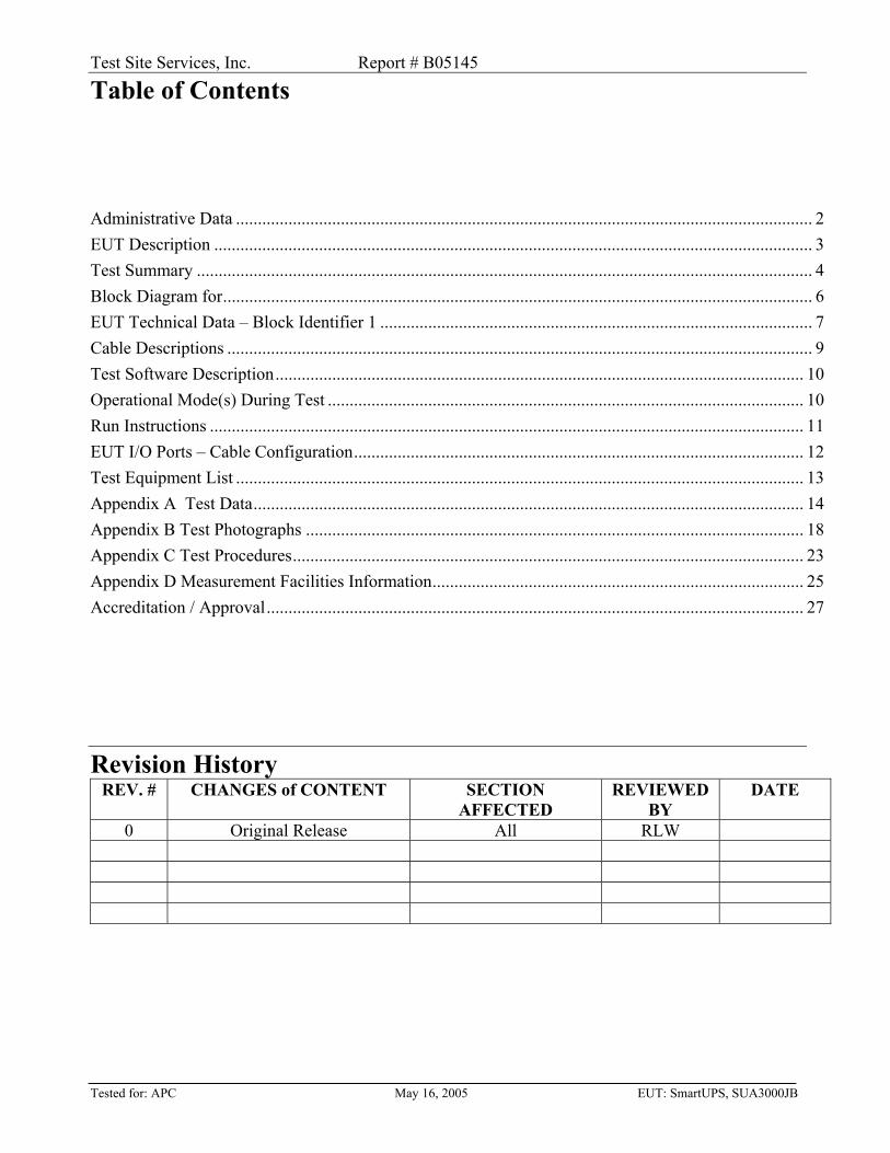
Table of Contents
Administrative Data .................................................................................................................................... 2 EUT Description ......................................................................................................................................... 3 Test Summary ............................................................................................................................................. 4 Block Diagram for....................................................................................................................................... 6 EUT Technical Data – Block Identifier 1 ................................................................................................... 7 Cable Descriptions ...................................................................................................................................... 9 Test Software Description......................................................................................................................... 10 Operational Mode(s) During Test ............................................................................................................. 10 Run Instructions ........................................................................................................................................ 11 EUT I/O Ports – Cable Configuration....................................................................................................... 12 Test Equipment List .................................................................................................................................. 13 Appendix A Test Data.............................................................................................................................. 14 Appendix B Test Photographs .................................................................................................................. 18 Appendix C Test Procedures..................................................................................................................... 23 Appendix D Measurement Facilities Information..................................................................................... 25 Accreditation / Approval........................................................................................................................... 27
Revision History REV. # CHANGES of CONTENT SECTION
AFFECTED REVIEWED
BY DATE
0 Original Release All RLW
Test Site Services, Inc. Report # B05145 Page 1 of 27
Tested for: APC May 16, 2005 EUT: SmartUPS, SUA3000JB
EMI Test Report for
CMG
Test Number : B05145 Product Name : SmartUPS, SUA3000JB Date : May 16, 2005
Report Issued By: Richard L. Wiedeman, Laboratory Director Tested By:
Adam Chubka, Test Technician Radiated & Conducted Emissions
This test report is not valid without the signatures of Test Site Services, Inc. personnel.
Test Site Services, Inc. Report # B05145 Page 2 of 27
Tested for: APC May 16, 2005 EUT: SmartUPS, SUA3000JB
Administrative Data Regulation : VCCI (Japan) Level : Class A (Emissions) Test Method : ANSI C63.4- (2003) : CISPR 22 (1997) : V3/2005.04
:
Test Type : Qualification Manufacturer : American Power Conversion EUT Type/Model # : SmartUPS, SUA3000JB Date(s) of Test : May 16, 2005 Customer Personnel
: William Hammond
TSS Personnel : R. Wiedeman EMC Engineer CMG Personel : Adam Chubka Test Technician Test Location(s)
202 Forest St. Malborough, MA 01752
U.S.A.
EUT Returned Via: Customer Pickup
Test Site Services, Inc. Report # B05145 Page 3 of 27
Tested for: APC May 16, 2005 EUT: SmartUPS, SUA3000JB
EUT Description
The EUT is an Uninterruptible power supply (UPS) that provides backup electrical power during black outs.
A complete description of the EUT may be found on Block Identifier 1. The tests were run in a typical configuration including the following equipment:
SUPPORT EQUIPMENT LIST Type of Device Part Number Serial Number Manufacturer
Resistive Load N/A N/A Avtron Web Card AP9619 APC
REASON FOR TEST: Qualification. CHANGES MADE DURING TEST: None. DEVIATIONS FROM STANDARD TEST METHOD: None.
Test Site Services, Inc. Report # B05145 Page 4 of 27
Tested for: APC May 16, 2005 EUT: SmartUPS, SUA3000JB
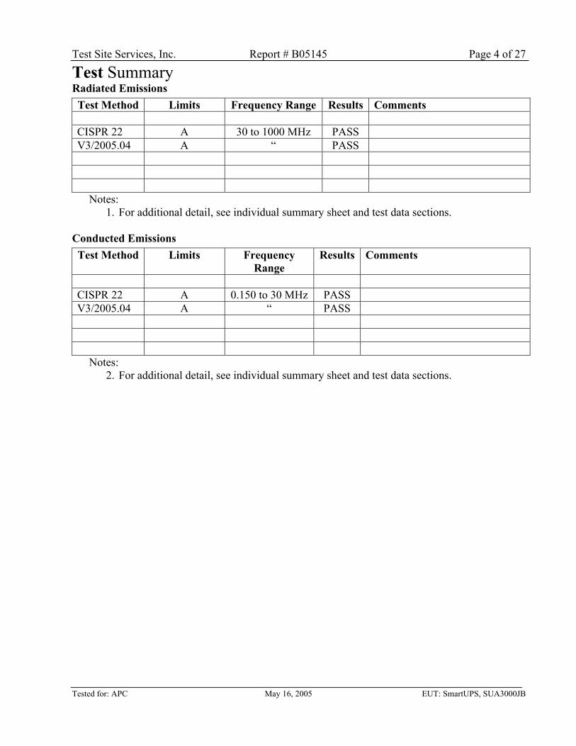
Test Summary Radiated Emissions
Test Method Limits Frequency Range Results Comments CISPR 22 A 30 to 1000 MHz PASS V3/2005.04 A “ PASS
Notes: 1. For additional detail, see individual summary sheet and test data sections.
Conducted Emissions
Test Method Limits Frequency Range
Results Comments
CISPR 22 A 0.150 to 30 MHz PASS V3/2005.04 A “ PASS
Notes: 2. For additional detail, see individual summary sheet and test data sections.
Test Site Services, Inc. Report # B05145 Page 5 of 27
Tested for: APC May 16, 2005 EUT: SmartUPS, SUA3000JB
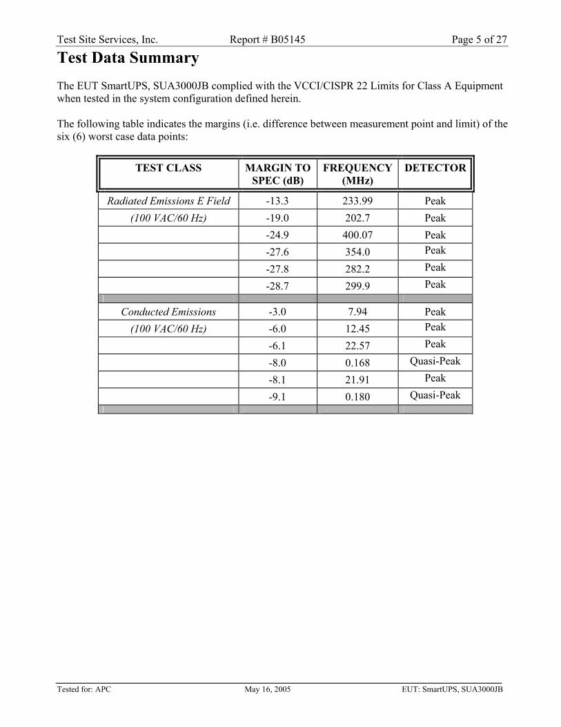
Test Data Summary The EUT SmartUPS, SUA3000JB complied with the VCCI/CISPR 22 Limits for Class A Equipment when tested in the system configuration defined herein. The following table indicates the margins (i.e. difference between measurement point and limit) of the six (6) worst case data points:
TEST CLASS MARGIN TO SPEC (dB)
FREQUENCY (MHz)
DETECTOR
Radiated Emissions E Field -13.3 233.99 Peak (100 VAC/60 Hz) -19.0 202.7 Peak
Test Site Services, Inc. Report # B05145 Page 6 of 27
Tested for: APC May 16, 2005 EUT: SmartUPS, SUA3000JB
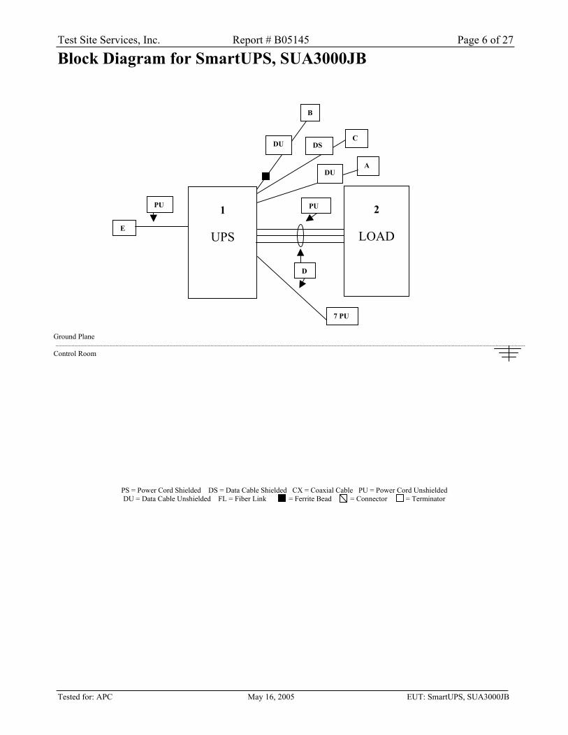
Block Diagram for SmartUPS, SUA3000JB Ground Plane Control Room
PS = Power Cord Shielded DS = Data Cable Shielded CX = Coaxial Cable PU = Power Cord Unshielded DU = Data Cable Unshielded FL = Fiber Link = Ferrite Bead = Connector = Terminator
1
UPS
2
LOAD
7 PU
D
PU
DSC
ADU
B
DU
E
PU
Test Site Services, Inc. Report # B05145 Page 7 of 27
Tested for: APC May 16, 2005 EUT: SmartUPS, SUA3000JB
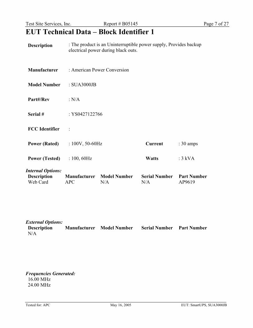
EUT Technical Data – Block Identifier 1
Description : The product is an Uninterruptible power supply, Provides backup electrical power during black outs.
Manufacturer : American Power Conversion Model Number : SUA3000JB Part#/Rev : N/A Serial # : YS0427122766 FCC Identifier : Power (Rated) : 100V, 50-60Hz Current : 30 amps Power (Tested) : 100, 60Hz Watts : 3 kVA
Internal Options: Description Manufacturer Model Number Serial Number Part Number Web Card APC N/A N/A AP9619
External Options: Description Manufacturer Model Number Serial Number Part Number N/A
Frequencies Generated: 16.00 MHz 24.00 MHz
Test Site Services, Inc. Report # B05145 Page 8 of 27
Tested for: APC May 16, 2005 EUT: SmartUPS, SUA3000JB
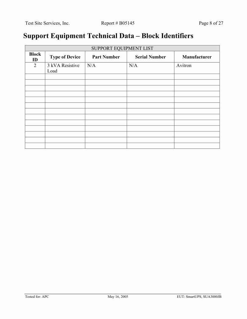
Support Equipment Technical Data – Block Identifiers
SUPPORT EQUIPMENT LIST Block
ID Type of Device Part Number Serial Number Manufacturer
2 3 kVA Resistive Load
N/A N/A Avitron
Test Site Services, Inc. Report # B05145 Page 9 of 27
Tested for: APC May 16, 2005 EUT: SmartUPS, SUA3000JB
Cable Descriptions
Cable ID
Number of Cables
Function Type Shielded
Y/N
Length Number of Conductors
Connector Shell Shielded
Y/N
Part Number Miscellaneous
A 1 Ethernet N 10 foot 8 N None B 1 USB N 10 foot 4 N None C 1 Serial N 10 foot 9 Y None D 10 Power N 6 foot 3 N None E 1 Input Power N 10 foot 3 N None F G H I J K L M N O P Q
Test Site Services, Inc. Report # B05145 Page 10 of 27
Tested for: APC May 16, 2005 EUT: SmartUPS, SUA3000JB
Test Software Description Software
Title: PowerChute
Part # / Rev.: N/A
Function: Ethernet, USB, RS-232 serial data
Repeat Time: Continuous
LAN Information:
Speed (Mb / Sec)
Data Pattern
Packet Length
Delay (µS) Bits / Sec % of Utilization
10/100 random 1 12 random 1
19.2kb random 1
Operational Mode(s) During Test Operational Mode(s) Available:
1. All LAN used to remotely monitor UPS status. 2. Charging
Mode(s) Tested:
1. Idle state (LAN). 2. UPS Charging with 3 kVA load
Function: LAN Used to remotely monitor UPS status. UPS used to backup electrical power
during black outs
Rationale: Ethernet Option board if customer needs remote monitoring.
Test Site Services, Inc. Report # B05145 Page 11 of 27
Tested for: APC May 16, 2005 EUT: SmartUPS, SUA3000JB
Run Instructions
1) Apply power and Turn on UPS. 2) Batteries will charge as needed. 3) All LAN is always active and ready for monitoring.
Test Site Services, Inc. Report # B05145 Page 12 of 27
Tested for: APC May 16, 2005 EUT: SmartUPS, SUA3000JB
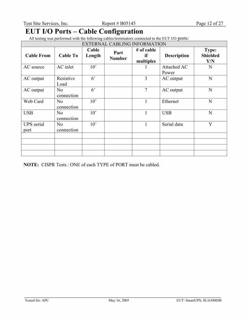
EUT I/O Ports – Cable Configuration All testing was performed with the following cables/terminators connected to the EUT I/O ports:
EXTERNAL CABLING INFORMATION
Cable From Cable To Cable
Length Part Number
# of cable if
multiples Description
Type: Shielded
Y/N AC source AC inlet 10’ 1 Attached AC
Power N
AC output Resistive Load
6’ 3 AC output N
AC output No connection
6’ 7 AC output N
Web Card No connection
10’ 1 Ethernet N
USB No connection
10’ 1 USB N
UPS serial port
No connection
10’ 1 Serial data Y
NOTE: CISPR Tests : ONE of each TYPE of PORT must be cabled.
Test Site Services, Inc. Report # B05145 Page 13 of 27
Tested for: APC May 16, 2005 EUT: SmartUPS, SUA3000JB
Test Equipment List
Test Equipment Serial # Calibration Due Chase model CBL6111 Biconilog Antenna 30-1000 MHz 1052 4/20/2006 HP model 8566B Spectrum Analyzer (SA) 2928A06006 3/02/2006 HP model 85662A Spectrum Analyzer Display 2848A18006 3/02/2006 HP model 85685A RF Preselector (RFP) 3010A01074 3/02/2006 HP model 85650A Quasi-Peak Adapter (QPA) 2043A00171 3/02/2006 HP model 8447D Preamplifier .1-1000 MHz 2727A05292 2/25/06 Andrew LDF2-50 radiated emissions cable RR-RE10M-02 1/22/2006
Test Site Services, Inc. Report # B05145 Page 14 of 27
Tested for: APC May 16, 2005 EUT: SmartUPS, SUA3000JB
Appendix A Test Data
TEST DATA
Test Site Services, Inc. Report # B05145 Page 15 of 27
Tested for: APC May 16, 2005 EUT: SmartUPS, SUA3000JB
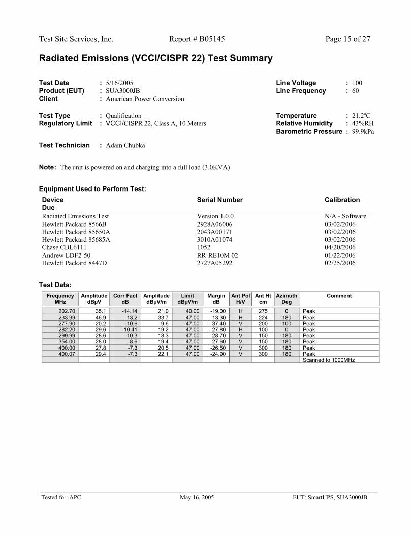
Radiated Emissions (VCCI/CISPR 22) Test Summary Test Date : 5/16/2005 Line Voltage : 100 Product (EUT) : SUA3000JB Line Frequency : 60 Client : American Power Conversion Test Type : Qualification Temperature : 21.2ºC Regulatory Limit : VCCI/CISPR 22, Class A, 10 Meters Relative Humidity : 43%RH Barometric Pressure : 99.9kPa Test Technician : Adam Chubka
Note : The unit is powered on and charging into a full load (3.0KVA)
Equipment Used to Perform Test:
Device Serial Number Calibration Due Radiated Emissions Test Version 1.0.0 N/A - Software Hewlett Packard 8566B 2928A06006 03/02/2006 Hewlett Packard 85650A 2043A00171 03/02/2006 Hewlett Packard 85685A 3010A01074 03/02/2006 Chase CBL6111 1052 04/20/2006 Andrew LDF2-50 RR-RE10M 02 01/22/2006 Hewlett Packard 8447D 2727A05292 02/25/2006
Test Data:
Frequency Amplitude Corr Fact Amplitude Limit Margin Ant Pol Ant Ht Azimuth Comment MHz dBµV dB dBµV/m dBµV/m dB H/V cm Deg
202.70 35.1 -14.14 21.0 40.00 -19.00 H 275 0 Peak 233.99 46.9 -13.2 33.7 47.00 -13.30 H 224 180 Peak 277.90 20.2 -10.6 9.6 47.00 -37.40 V 200 100 Peak 282.20 29.6 -10.41 19.2 47.00 -27.80 H 100 0 Peak 299.99 28.6 -10.3 18.3 47.00 -28.70 V 150 180 Peak 354.00 28.0 -8.6 19.4 47.00 -27.60 V 150 180 Peak 400.00 27.8 -7.3 20.5 47.00 -26.50 V 300 180 Peak 400.07 29.4 -7.3 22.1 47.00 -24.90 V 300 180 Peak
Scanned to 1000MHz
Test Site Services, Inc. Report # B05145 Page 16 of 27
Tested for: APC May 16, 2005 EUT: SmartUPS, SUA3000JB
EUT Conducted Emissions (VCCI/CISPR 22) Test Summary Test Date : 5/16/2005 Scan Number : CE001 Client : American Power Conversion Line Voltage : 100 Product (EUT) : SUA3000JB Line Frequency : 60 Test Technician : Adam Chubka Temperature : 21.3ºC Test Type : Qualification Relative Humidity : 40%RH Regulatory Limit : VCCI/CISPR22, Class A Barometric Pressure : 99.9kPa Device Under Test : SUA3000JB LISN Phase : L1
Note : The unit is powered on and charging into a full load (3.0KVA)
Equipment Used to Perform Test:
Device Serial Number Calibration Due Conducted Emissions Test Version 1.0.0 N/A - Test Software Hewlett Packard 8566B 2928A06006 03/02/2006 Hewlett Packard 85650A 2043A00171 03/02/2006 Hewlett Packard 85685A 3010A01074 03/02/2006 Rohde & Schwarz ESH2-Z5 843285/002 12/15/2005 Belden 9913 RR-CE01 12/20/2005
Test Data:
Frequency Corr Fact Pk Ampl QP Ampl QP Limit QP Margin Av Ampl Av Limit Av Margin Comment MHz dB dBµV dBµV dBµV dB dBµV dBµV dB
.1800 .15 62.00 56.90 79.00 -22.10 N/A 66.00 N/A QP = -9.1 dB < Av lim
.4800 .18 50.20 N/A 79.00 N/A N/A 66.00 N/A Pk = -15.8 dB < Av lim7.9400 .74 57.00 N/A 73.00 N/A N/A 60.00 N/A Pk = -3.0 dB < Av lim8.1200 .76 54.40 47.60 73.00 -25.40 N/A 60.00 N/A QP = -12.4 dB < Av lim
12.2100 1.04 53.50 N/A 73.00 N/A N/A 60.00 N/A Pk = -6.5 dB < Av lim12.7200 1.08 51.00 N/A 73.00 N/A N/A 60.00 N/A Pk = -9.0 dB < Av lim13.2200 1.11 48.00 N/A 73.00 N/A N/A 60.00 N/A Pk = -12.0 dB < Av lim21.8800 2.39 57.20 46.50 73.00 -26.50 N/A 60.00 N/A QP = -13.5 dB < Av lim22.6000 2.56 54.40 43.90 73.00 -29.10 N/A 60.00 N/A QP = -16.1 dB < Av lim22.8100 2.61 52.70 N/A 73.00 N/A N/A 60.00 N/A Pk = -7.3 dB < Av lim23.1300 2.68 49.60 N/A 73.00 N/A N/A 60.00 N/A Pk = -10.4 dB < Av lim
Test Site Services, Inc. Report # B05145 Page 17 of 27
Tested for: APC May 16, 2005 EUT: SmartUPS, SUA3000JB
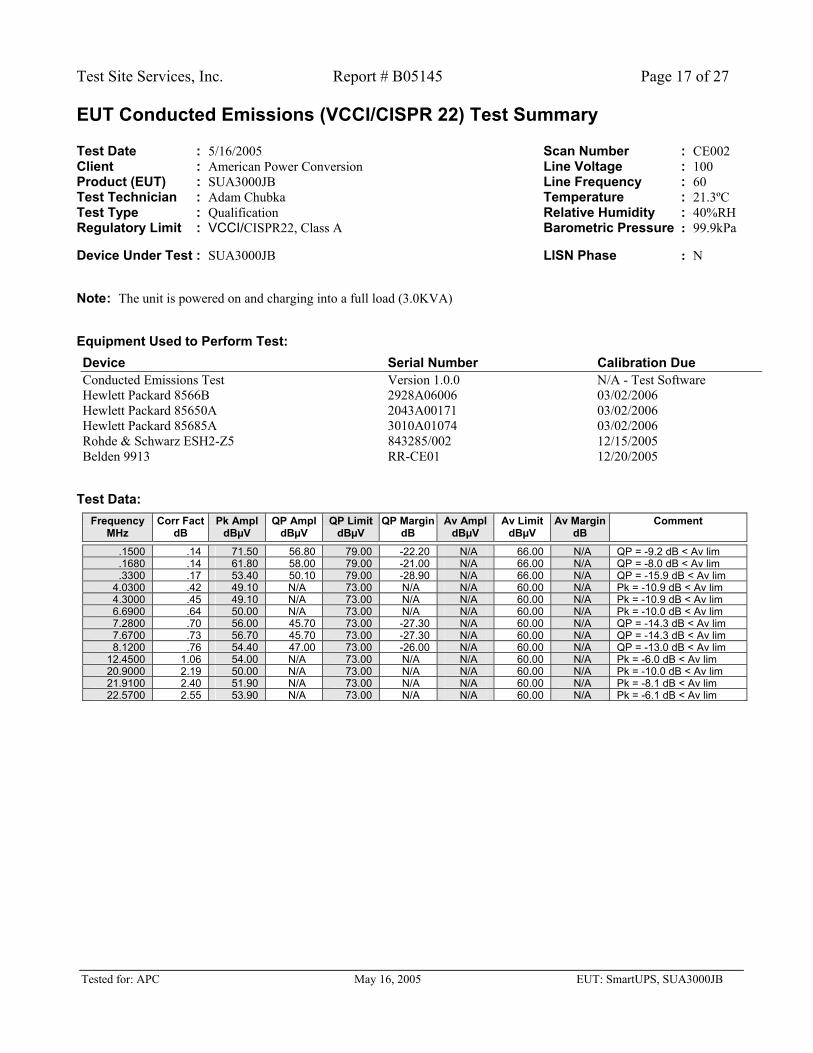
EUT Conducted Emissions (VCCI/CISPR 22) Test Summary Test Date : 5/16/2005 Scan Number : CE002 Client : American Power Conversion Line Voltage : 100 Product (EUT) : SUA3000JB Line Frequency : 60 Test Technician : Adam Chubka Temperature : 21.3ºC Test Type : Qualification Relative Humidity : 40%RH Regulatory Limit : VCCI/CISPR22, Class A Barometric Pressure : 99.9kPa Device Under Test : SUA3000JB LISN Phase : N
Note : The unit is powered on and charging into a full load (3.0KVA)
Equipment Used to Perform Test:
Device Serial Number Calibration Due Conducted Emissions Test Version 1.0.0 N/A - Test Software Hewlett Packard 8566B 2928A06006 03/02/2006 Hewlett Packard 85650A 2043A00171 03/02/2006 Hewlett Packard 85685A 3010A01074 03/02/2006 Rohde & Schwarz ESH2-Z5 843285/002 12/15/2005 Belden 9913 RR-CE01 12/20/2005
Test Data:
Frequency Corr Fact Pk Ampl QP Ampl QP Limit QP Margin Av Ampl Av Limit Av Margin Comment MHz dB dBµV dBµV dBµV dB dBµV dBµV dB
.1500 .14 71.50 56.80 79.00 -22.20 N/A 66.00 N/A QP = -9.2 dB < Av lim
.1680 .14 61.80 58.00 79.00 -21.00 N/A 66.00 N/A QP = -8.0 dB < Av lim
.3300 .17 53.40 50.10 79.00 -28.90 N/A 66.00 N/A QP = -15.9 dB < Av lim4.0300 .42 49.10 N/A 73.00 N/A N/A 60.00 N/A Pk = -10.9 dB < Av lim4.3000 .45 49.10 N/A 73.00 N/A N/A 60.00 N/A Pk = -10.9 dB < Av lim6.6900 .64 50.00 N/A 73.00 N/A N/A 60.00 N/A Pk = -10.0 dB < Av lim7.2800 .70 56.00 45.70 73.00 -27.30 N/A 60.00 N/A QP = -14.3 dB < Av lim7.6700 .73 56.70 45.70 73.00 -27.30 N/A 60.00 N/A QP = -14.3 dB < Av lim8.1200 .76 54.40 47.00 73.00 -26.00 N/A 60.00 N/A QP = -13.0 dB < Av lim
12.4500 1.06 54.00 N/A 73.00 N/A N/A 60.00 N/A Pk = -6.0 dB < Av lim20.9000 2.19 50.00 N/A 73.00 N/A N/A 60.00 N/A Pk = -10.0 dB < Av lim21.9100 2.40 51.90 N/A 73.00 N/A N/A 60.00 N/A Pk = -8.1 dB < Av lim22.5700 2.55 53.90 N/A 73.00 N/A N/A 60.00 N/A Pk = -6.1 dB < Av lim
Test Site Services, Inc. Report # B05145 Page 18 of 27
Tested for: APC May 16, 2005 EUT: SmartUPS, SUA3000JB
Appendix B Test Photographs
TEST PHOTOGRAPHS
Test Site Services, Inc. Report # B05145 Page 19 of 27
Tested for: APC May 16, 2005 EUT: SmartUPS, SUA3000JB
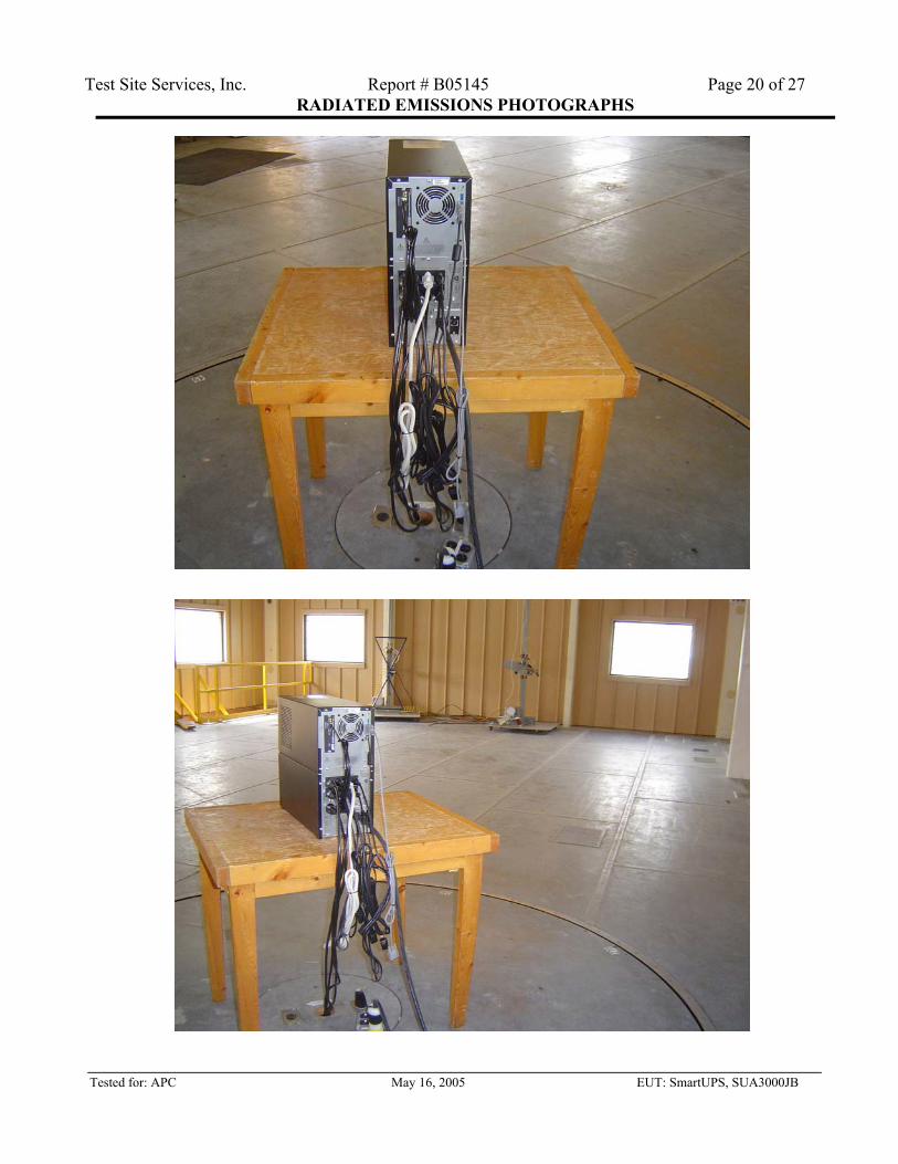
RADIATED EMISSIONS PHOTOGRAPHS
Test Site Services, Inc. Report # B05145 Page 20 of 27
Tested for: APC May 16, 2005 EUT: SmartUPS, SUA3000JB
RADIATED EMISSIONS PHOTOGRAPHS
Test Site Services, Inc. Report # B05145 Page 21 of 27
Tested for: APC May 16, 2005 EUT: SmartUPS, SUA3000JB
CONDUCTED EMISSIONS PHOTOGRAPHS
Test Site Services, Inc. Report # B05145 Page 22 of 27
Tested for: APC May 16, 2005 EUT: SmartUPS, SUA3000JB
CONDUCTED EMISSIONS PHOTOGRAPHS
Test Site Services, Inc. Report # B05145 Page 23 of 27
Tested for: APC May 16, 2005 EUT: SmartUPS, SUA3000JB
Appendix C Test Procedures
TEST PROCEDURES
Test Site Services, Inc. Report # B05145 Page 24 of 27
Tested for: APC May 16, 2005 EUT: SmartUPS, SUA3000JB
Test Procedures - EMI Operational Description GENERAL
For each emission signal, maximum level is achieved for both horizontal and vertical polarizations as well as (0-360) degrees turntable rotation. Antenna Test Distances are selected at either 3, 10 or 30 meters separation from the EUT in accordance with applicable specification requirements. Antenna Scan Heights are varied from 1-4 meters at Antenna Test Distances of 3, 10 and 30 meters.
FCC RADIATED EMISSIONS (E-FIELD) EMI test procedures are performed in accordance with the requirements of ANSI C63.4 (1992). Measurements are initially obtained using broad band antennas and PEAK detection. In addition, cables are manipulated to maximize emissions within constraints of a typical system configuration. All measured data within 3 db of the Radiated Limits are retaken using Tuned Dipole Antennas (Roberts Type) and QUASI-PEAK (CISPR) Detection. Each EUT is powered from a 60Hz AC source except a 50 Hz source is used when CISPR Limits are applicable.
FCC CONDUCTED EMISSIONS EMI test procedures are performed in accordance with the requirements ANSI C63.4 (1992). Measurements are initially obtained with PEAK Detection. In addition, cables are manipulated to maximize emissions within constraints of a typical system configuration. All measured data within 3 db of the Conducted Limits are retaken using QUASI-PEAK (CISPR) Detection. Each EUT is powered from a 60Hz AC source.
CISPR22/EN55022 RADIATED EMISSIONS (E FIELD) EMI test procedures are operated in accordance with the requirements of the CISPR22 (1997) and EN55022 (1998) Documents. Measurements are initially obtained with PEAK Detection. In addition, cables are manipulated to maximize emissions within constraints of a typical system configuration. All measured data within 3 db of the Radiated Limits are retaken using QUASI-PEAK (CISPR) detection. Each EUT is powered from a 50Hz AC source.
CISPR22/EN55022 CONDUCTED EMISSIONS EMI test procedures are operated in accordance with the requirements of the CISPR22 (1997) and EN55022 (1998) Documents. Measurements are initially obtained with PEAK Detection. In addition, cables are arranged per the specification within constraints of a typical system configuration. All measured data exceeding 3 db below the Conducted QP Limit are retaken using QUASI-PEAK (CISPR) Detection. All measured data exceeding 2 db below the Conducted AVERAGE Limit are retaken using AVERAGE (CISPR) Detection. Each EUT is powered from a 50Hz AC source.
Test Site Services, Inc. Report # B05145 Page 25 of 27
Tested for: APC May 16, 2005 EUT: SmartUPS, SUA3000JB
Appendix D Measurement Facilities Information
MEASUREMENT FACILITIES INFORMATION
Test Site Services, Inc. Report # B05145 Page 26 of 27
Tested for: APC May 16, 2005 EUT: SmartUPS, SUA3000JB
DESCRIPTION of MEASUREMENT FACILITIES The Open Area Test Site (OATS) is composed of a building and associated ground screen with a control room underneath. The building is a TUFF-SPAN enclosure constructed of fiberglass reinforced plastic materials which provide above-ground weather protection. These materials are non conductive, non magnetic and RF transparent. They do not impact the surrounding electromagnetic environment and are corrosion resistant. The enclosure size permits Ten Meter Radiated Measurements within its confines and utilizes a remote controlled Macton Turntable Assembly. The conductive turntable is 16 feet in diameter and capable of moving a 10,000 pound load a full 360 degrees of rotation. It is flush-mounted to the ground screen and edge bonded circumferentially to the ground screen with beryllium copper "fingers". The ground screen is constructed of welded wire mesh lying directly on top of a concrete-over-steel foundation. The screen is extended beyond the building itself to provide 30 meter measurement capability when needed. There are no reflecting objects within the required obstruction free oval area. The control room is located beneath the ground screen level with stairwell access to the ground plane area. An elevator is located beyond the ground screen and provides access to the control room, shipping dock and ground screen areas for large sized EUT's. Primary power cabling to the EUT is fed through a hole in the center of the table along with necessary EUT/Support Equipment interface cabling. A remote controlled EMCO Antenna Mast Assembly is located on the ground screen. It provides the operator with adjustable antenna height over the 1 meter through 4 meter range as well as allowing both horizontal and vertical polarizations at any height. A conducted emissions measurement area is located in a shielded room and consists of a conductive (galvanized sheet metal) wall 20' wide x 8' high with a metal floor bonded to the wall. AC Power is supplied through receptacles located on the vertical wall. Each receptacle is adequately filtered using Shielded Room EMI Power Line Filters (Rayproof 1B42 Units) which provide 100 db attenuation over the 14KHz to 10GHz frequency range. The shielded room itself is bonded directly to earth ground. Additionally, both the control room/shielded rooms and ground plane area have heating, air conditioning and relative humidity controlled environments.
Test Site Services, Inc. Report # B05145 Page 27 of 27
Tested for: APC May 16, 2005 EUT: SmartUPS, SUA3000JB
Capability Test Site Service’s open area Test Sites have been evaluated in accordance with ANSI C63.4 procedures and found to be in compliance with ANSI C63.4-(1992) Site Attenuation and LISN requirements. In addition, Test Site Services is Assessed and Approved annually by a European Competent Body to assure competence in testing products for CE Mark Compliance (Emissions and Immunity). All of Test Site Service’s measurement facilities meet the technical requirements for qualification testing of products to FCC, CISPR, IEC, VCCI, BSMI and other International Standards.
Tested for: APC May 16, 2005 EUT: SmartUPS, SUA3000JB
EMC Facility Client Satisfaction Questionnaire Thank you for choosing to use the Test Site Services EMC test facilities to test your product. Client satisfaction is very important to Test Site Services. To help serve you fully and continue to make improvements in our service, we need your feedback and comments on the service we performed for you today. We would appreciate your taking a few moments to complete this questionnaire. 1. Did scheduling meet your needs 2. Test operator support 3. Personnel attitude 4. Efficiency of test process 5. Work completed in a timely manner 6. Report received in a timely manner 7. Report content and clarity 8. Overall rating 9. Additional Comments: Test Date: / / Completed By: _ _ _ _ _ _ _ _ _ _ _ _ _ _ _ _ _ _ _ _ _ _ _ _ _ _ _ _ _ _ _ _ _ _ _ _ _ _ _ _ _ _ _ _ _ _ _ _ _ _ Please return to: Lab Manager or Richard L. Wiedeman
(At Test Site) President Test Site Services, Inc. PO Box 766 Marlboro, MA 01752


![INDEX [meanwell.com]meanwell.com/Upload/PDF/meanwell_LED.pdf · APC-8, APC-12, APC-16, APC-25, APC-35 3 APV-8E, APV-12E, APV-16E 4 APC-8E, APC-12E, APC-16E LP ... Over voltage protection](https://static.documents.pub/doc/80x56/5b619e107f8b9a40488c919f/index-apc-8-apc-12-apc-16-apc-25-apc-35-3-apv-8e-apv-12e-apv-16e-4.jpg)


