TESTING AND COMMISSIONING PROCEDURE FOR SWIMMING POOL WATER TREATMENT INSTALLATION IN GOVERNMENT BUILDINGS OF THE HONG KONG SPECIAL ADMINISTRATIVE REGION 2017 EDITION ARCHITECTURAL SERVICES DEPARTMENT THE GOVERNMENT OF THE HONG KONG SPECIAL ADMINISTRATIVE REGION
Transcript
TESTING AND COMMISSIONING PROCEDURE
FOR
SWIMMING POOL WATER TREATMENT INSTALLATION
IN
GOVERNMENT BUILDINGS
OF
THE HONG KONG SPECIAL ADMINISTRATIVE REGION
2017 EDITION
ARCHITECTURAL SERVICES DEPARTMENT THE GOVERNMENT OF THE HONG KONG SPECIAL ADMINISTRATIVE REGION
PREFACE This Testing and Commissioning (T&C) Procedure aims to lay down the minimum testing and commissioning requirements to be carried out on Swimming Pool Water Treatment Installation in Government Buildings of the Hong Kong Special Administrative Region (HKSAR). Such requirements are applicable to both new installations upon completion and existing ones after major alteration. The present edition was developed from the 2012 edition by the Air-conditioning Specialist Support Group that was established under the Building Services Branch Technical Information and Research & Development Committee of the Architectural Services Department (ArchSD). This T&C Procedure has incorporated the latest changes in the 2017 edition of the General Specification for Swimming Pool Water Treatment Installation. With the benefit of information technology, electronic version of this T&C Procedure is to be viewed on and free for download from the ArchSD Internet homepage. As part of the Government’s efforts to limit paper consumption, hard copies of this T&C Procedure will not be put up for sale. The ArchSD welcomes comments on this T&C Procedure at any time since the updating of this T&C Procedure is a continuous process to tie in with technological advances.
DISCLAIMER
This T&C Procedure is solely compiled for use on Swimming Pool Water Treatment Installation carried out for or on behalf of the ArchSD in Government Buildings of the HKSAR. There are no representations, either expressed or implied, as to the suitability of this T&C Procedure for purposes other than that stated above. The material contained in this T&C Procedure may not be pertinent or fully cover the extent of the installation in non-government buildings. Users who choose to adopt this T&C Procedure for their works are responsible for making their own assessments and judgement of all information contained herein. The ArchSD does not accept any liability and responsibility for any special, indirect or consequential loss or damage whatsoever arising out of or in connection with the use of this T&C Procedure or reliance placed on it.
Table of Contents Page 1 of 2
SP_TCP 2017 Edition
TABLE OF CONTENTS
Page 1. Introduction 1 2. Objectives of the Testing and Commissioning Works 1-2 3. Scope of the Testing and Commissioning Works
2-4
3.1 Tests and Inspections during Construction
3.2 Functional Performance Tests
3.3 Statutory Tests and Inspections
3.4 Documentation and Deliverables 4. Testing and Commissioning Procedures
4-15
4.1 Tests and Inspections during Construction
4.1.1 Works Tests
4.1.2 Weld in Piped Services
4.1.3 Pressure Testing of Piped Services 4.2 Pre-commissioning Check
4.2.1 Water Distribution System
4.2.2 Filtration System 4.3 Tests for Systems and Equipment
4.3.1 Water Distribution System
4.3.2 Filtration System
4.3.3 Disinfection System
4.3.4 Hot Water Boiler and Calorifier System
4.3.5 Portable Pool Cleaning Equipment
4.3.6 Performance Tests
4.3.7 Noise and Sound Tests
4.3.8 Vibration Tests
Table of Contents Page 2 of 2
SP_TCP 2017 Edition
Annex Annex Page
Annex I Testing and Commissioning Progress Chart for Swimming Pool Water Treatment Installation
1-4
Annex II Testing and Commissioning Certificate on Swimming Pool Water
Treatment Installation
1-11
Part 1: Details of Project
Part 2: Declaration
Part 3: Items Inspected and Tested
3.1 General Requirement as indicated in the T&C procedure
have been complied
3.2 Pre-commissioning Checks
3.3 Setting to Work & Balancing
3.4 Performance Tests
3.5 Record of Tests
3.6 Comments
Part 4: Test Record attached to the Test Certificate 4.1 Test Data
4.2 Testing Equipment/Instrument Annex III List of Calibrated Equipment/Instruments Necessary for the
Testing and Commissioning Works 1
Page 1 of 15
SP_TCP 2017 Edition
Testing and Commissioning Procedure for Swimming Pool Water Treatment Installation
1 Introduction
The procedures stated in this Testing and Commissioning (T&C) Procedure cover the activities in preliminary tests and inspections, functional performance tests and the commissioning of newly completed installations and existing ones after major alteration. They are so compiled to facilitate the work of Project Building Services Engineer (PBSE) and Project Building Services Inspector (PBSI), who are appointed as the Supervising Officer’s Representatives, in the following aspects with respect to testing and commissioning:- (a) to vet and approve the T&C procedures proposed and submitted by the
contractor for Swimming Pool Water Treatment Installation (SP Contractor);
(b) to witness those T&C procedures as specified; and (c) to accept the T&C certificates and other supporting data. The SP Contractor shall carry out the T&C works as detailed in this T&C Procedure. Supplementary T&C plans may be proposed by the SP Contractor as appropriate and agreed by PBSE, e.g. for special equipment supplied and/or installed by the SP Contractor. The administrative requirements for T&C works are in general as specified in the General Specification for Swimming Pool Water Treatment Installation 2017 Edition and all current corrigenda/amendments thereto published before the date of first tender invitation for the Contract issued by the ArchSD (the General Specification). All words and expressions shall have the meaning as assigned to them under the General Specification unless otherwise specified herein.
2. Objectives of the Testing and Commissioning Works
The objectives of the T&C works are:- (a) to verify proper functioning of the equipment/system after installation; (b) to verify that the performance of the installed equipment/systems meet
with the specified design intent and statutory requirements, if any, through a series of tests and adjustments; and
(c) to capture and record performance data of the whole installation as the
baseline for future operation and maintenance. For the avoidance of doubt, depending on the specific demands of individual installation, the PBSE may require additional or substitute T&C works in regard
Page 2 of 15
SP_TCP 2017 Edition
to any elements in the Installations other than those indicated in this T&C Procedure.
3. Scope of the Testing and Commissioning Works
3.1 Tests and Inspections during Construction
The purpose of these tests is to ensure that all components and systems are in a satisfactory and safe condition before start up. Preliminary adjustment and setting of equipment at this stage shall also be carried out at the same time to pave way for the coming functional performance tests. Before carrying out any test, the SP Contractor shall ensure that the Installations comply with all relevant statutory requirements and regulations. The T&C works shall also comply with all site safety regulatory requirements currently in force. In particular, the SP Contractor shall note the following:-
(a) Occupational Safety and Health Ordinance (Cap. 509), and other
subsidiary legislation made under the Ordinance; (b) Factories and Industrial Undertakings Ordinance (Cap. 59), and other
subsidiary legislation made under the Ordinance, including but not limited to Construction Sites (Safety) Regulations;
(c) Construction Site Safety Manual issued by Development Bureau, the
Government of the HKSAR; (d) Fire Services Ordinance (Cap. 95); (e) Dangerous Goods Ordinance (Cap. 295); (f) Waste Disposal Ordinance (Cap. 354); (g) Boilers and Pressure Vessels Ordinance (Cap. 56); (h) Gas Safety Ordinance (Cap. 51); (i) Occupational Safety and Health Ordinance (Cap. 509); (j) Electricity Ordinance (Cap. 406), and other subsidiary legislation made
under the Ordinance; (k) Code of Practice for the Electricity (Wiring) Regulations published by
Electrical and Mechanical Services Department, the Government of the HKSAR; and
(l) Electricity supply rules of the relevant power supply companies. (m) Buildings Energy Efficiency Ordinance (Cap 610).
Page 3 of 15
SP_TCP 2017 Edition
3.2 Functional Performance Tests
The purpose of functional performance tests is to demonstrate that the Installations can meet the functional and performance requirements as specified in the Specification. Functional performance tests should proceed from the testing of individual components to the testing of different systems in the Installations. The SP Contractor may have to make temporary modifications as the tests proceed. The specific tests required and the order of tests will vary depending on the type and size of systems, number of systems, sequence of construction, interface with other installations, relationship with the building elements and other specific requirements as indicated in the Specification. The testing of systems may have to be carried out in stages depending on the progress of work or as proposed by the SP Contractor. Part of the tests may be required to be carried out in suppliers’ premises in accordance with the provisions in the Specification. Any performance deficiencies revealed during the functional performance tests must be evaluated to determine the cause. After completion of the necessary corrective measures, the SP Contractor shall repeat the tests. If any test cannot be completed because of circumstances that are beyond the control of the SP Contractor, it shall be properly documented and reported to the PBSE, who shall then liaise with the relevant parties to resolve the situation. The SP Contractor shall resume his testing work immediately upon the attainment of a suitable testing environment.
3.3 Statutory Tests and Inspections
The SP Contractor shall carry out tests for the Installations to meet statutory requirements as specified in the Specification. After the proper testing and commissioning of the Installations, the SP Contractor shall notify the appropriate authority as specified in the Specification, through the PBSE of the completion of the Installations and its readiness for inspection and testing. The SP Contractor shall arrange for the necessary inspections and tests as required by the Authority.
3.4 Documentation and Deliverables
The SP Contractor shall submit his proposed T&C procedures together with the Testing and Commissioning Progress Chart shown in Annex I to PBSE for approval. All inspection and T&C results shall be recorded by the SP Contractor in the appropriate test record forms. A complete set of these forms can be found in Annex II.
Page 4 of 15
SP_TCP 2017 Edition
Data recorded in other formats may also be acceptable subject to prior approval of the PBSE. Upon completion of all the required T&C works, the SP Contractor shall complete and sign a testing and commissioning certificate as shown in Annex II to the effect that the agreed T&C works have been duly carried out. A functional performance test report covering all measured data, data sheets, and a comprehensive summary describing the operation of the system at the time of the functional performance tests shall be prepared and submitted to the PBSE. Deviations in performance from the Specification or the design intent should be recorded, with a description and analysis included. Where required in the Specification, the SP Contractor shall conduct a final evaluation of the performance of the Installations, the results of which shall be included in the commissioning report.
4. Testing and Commissioning Procedures
The SP Contractor shall employ trained, experienced engineer to carry out the T&C procedure and for specialised items such as gas chlorination system, ozone dosing system, boiler system, etc., they may be carried out by the manufacturer's own testing and commissioning engineers if necessary. Before operating the system to carry out T&C, the SP Contractor shall follow steps as listed below:- (a) obtain design drawings and specifications and become thoroughly
acquainted with the design intent; (b) obtain copies of approved shop drawings of all water handling
equipment, outlets (supply, return), boiler, gas chlorinator, chemical dosing system, etc.;
(c) compare design to installed equipment and field installation; (d) walk through the system from the water and other fluid handling
equipment to the terminal units to determine any variations of installation from design; and
(e) obtain schematic diagrams of system and as-built piping layouts to
facilitate reporting. 4.1 Tests and Inspections during Construction
4.1.1 Works Tests
(i) Works tests shall follow the T&C Procedure normally associated with the specific item of equipment and to the standards as laid down in the Specification and Drawings.
Page 5 of 15
SP_TCP 2017 Edition
(ii) Works static pressure tests will be carried out on such items of plant and equipment as pressure vessels, water coils, heat exchangers, filter bed tanks, and all items of plant or equipment if provisions have been made in the Specification and Drawings.
(iii) Dynamic rotation tests will be carried out on items such as fan
impellers and drives, pump impellers and drives. Tests shall be conducted through the entire rotational speed range up to a maximum of 150% designed operating speed if the provision has been made in the Specification and Drawings. When items of plant are purchased ex-stock, a manufacturers test certificate will suffice.
(iv) Rotational test on electric motors will not be carried out if the
equipment are constructed to the requisite current British Standard or any other approved international standards.
(v) Operational test on the chlorine gas leakage detection system. (vi) Water quality test. (vii) Operational test on the loose supplied items such as pool cleaners
and pool covers.
4.1.2 Weld in Piped Services
For this part of test, refer to the relevant section(s) of the "Testing and Commissioning Procedure for Air-conditioning, Refrigeration, Ventilation and Central Monitoring & Control System Installation."
4.1.3 Pressue Testing of Piped Services
For this part of test, refer to the relevant section(s) of the "Testing and Commissioning Procedure for Air-conditioning, Refrigeration, Ventilation and Central Monitoring & Control System Installation."
4.2 Pre-commissioning Check
4.2.1 Water Distribution System
Check the following items with reference to the corresponding sections in the "Testing and Commissioning Procedure for Air-conditioning, Refrigeration, Ventilation and Central Monitoring & Control System Installation" :- (a) System Cleanliness; (b) State of System; (c) System Readiness before Filling up; (d) Mechanical Checks for Pumps, Motorised Valves and Float
Switches;
Page 6 of 15
SP_TCP 2017 Edition
(e) System Filling; and (f) Electrical Checks With and Without all Electrical Supplies
Isolated.
4.2.2 Filtration System
Normally for conventional type pool filtration system, filtering of the water is by sand bed filters. For other systems reference should be made to the particular equipment manufacturer's published instructions. State of System Check that :- (i) filter beds are set on concrete kerb or slab and are level; (ii) the correct grade and depth of sand has been installed against the
manufacturer's filter data label; (iii) pump strainer basket is in proper position and lid is properly
secured; and (iv) all inspection doors are properly closed after inspection and that all
valves are set in their proper position for initial starting up. 4.3 Tests for Systems and Equipment
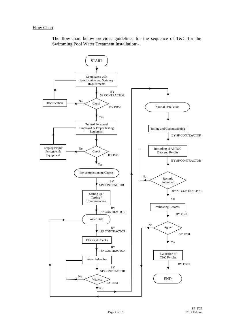
The SP Contractor shall carry out the tests and inspections as shown in Part 3 of Annex II and record the test results on Part 4 of Annex II and as agreed by the PBSE. The SP Contractor shall provide all necessary staff, labour, materials and equipment for a thorough test and examination of the Installations. The SP Contractor is required to carry out a full T&C process for the equipment and the complete system to ascertain that the equipment and the system are operating in accordance with the design objectives. T&C of the Installations shall include but not limited to the following with T&C sequence as shown in the flow chart below:- (a) the balancing of water distribution; (b) adjustment of total system flow to provide designed quantities; (c) electrical measurements; (d) verification of performance of all equipment and automatic controls; and (e) sound and vibration measurements.
Page 7 of 15
SP_TCP 2017 Edition
Flow Chart
The flow-chart below provides guidelines for the sequence of T&C for the Swimming Pool Water Treatment Installation:-
BY SP CONTRACTOR
Yes
BY PBSI
BY SP CONTRACTOR
BY PBSI
No
Yes
BY PBSI
No
No
Yes
BY PBSE
BY PBSI
BY SP CONTRACTOR
BY SP CONTRACTOR
BY SP CONTRACTOR
BY SP CONTRACTOR
BY SP CONTRACTOR
No
BY SP CONTRACTOR
Yes
BY SP CONTRACTOR
No
Yes
Check Rectification
Compliance with Specification and Statutory
Requirements
START
END
Trained Personnel Employed & Proper Testing
Equipment
Employ Proper Personnel & Equipment
Check
Pre-commissioning Checks
Setting up / Testing /
Commissioning
Water Side
Electrical Checks
Special Installation
Testing and Commissioning
Recording of All T&C Data and Results
Records Submitted
Validating Records
Agree
Evaluation of T&C Results
BY PBSI
Water Balancing
Witness
Page 8 of 15
SP_TCP 2017 Edition
4.3.1 Water Distribution System
(a) General
It is not possible to embody every type of plant and piping layout for pool water flow patterns usually employed in the Installations. The T&C Procedure given here may have to be adapted to suit the particular arrangement.
(b) Procedure
The T&C Procedure required to achieve a water distribution system working satisfactorily and be regulated appropriately shall refer to the relevant and appropriate sections in the "Testing and Commissioning Procedure for Air-conditioning, Refrigeration, Ventilation and Central Monitoring & Control System Installation".
(c) Checks Prior to Pump Start-Up (d) Initial Starting and Running of Electrically Driven Centrifugal
Pump Set (e) Regulation of Water Flow
- Initial Checking on System Flow Rates - Final Regulation
(f) Other Regulating Valves
4.3.2 Filtration System
(a) Initial Starting-up
After the water has been filled to the correct pool level and that all mechanical and electrical checks on the circulation pumps are completed to satisfaction, initial start-up of the filter beds could then commence. (i) Set the corresponding valves in "filter" positions. (ii) Switch on the pump and run for approximately 5 minutes.
Note During this filtering cycle some remnant construction debris and pipe dirts will be carried and directed into the top of the filter and then trapped in the filter. The pressure across the filter bed as reflected in the differential pressure gauge provided will increase.
Page 9 of 15
SP_TCP 2017 Edition
(iii) After the prescribed time lapsed, turn off the pump and set all the necessary valves to "backwash" position.
(iv) Run the pump and air compressor and backwash for 6 to 8
minutes or until the water appears to be clean through the sight glass. The air supply must be kept at the manufacturer's recommended value and should not be exceeded.
(v) After "backwash" process is completed, turn off the pump
and reset all necessary valves to their "filter" position for normal operation.
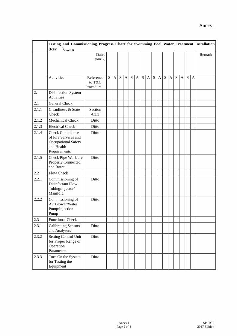
4.3.3 Disinfection System
There are several different systems for water disinfection, e.g. ozone generation system, sodium hypochlorite generation system, mixed oxidant disinfection system, and ultra violet light disinfection system. This T&C Procedure concentrates on the above types of disinfection systems. Check Prior to Start up (a) Ozone generation system
(i) Check that all pipework and their associated connections are tight, all the strainers are free of dirt, all the valves are in the correct positions and flow alignment, their connections are tight and that all other relevant fire services as well as occupational safety and health requirements of the gaseous ozone or ozonated water and the ozone generator room are complied with.
(ii) Check the power and control cables to all equipment and
controllers in the system for correct material, sizing and installation, and the provision of all necessary earth terminals and their interconnections are tight and tally with the details on the approved shop drawings, then carry out Meggar test on the metal casing of all equipment and for every motor starter to ensure that they are properly earthed in particular for the door earth strap and earth terminals of the casing, and finally test the proper function of the power supply of the whole system for electrical safety protection.
(iii) Check any air blowers in the system and the associated
equipment by hand for smooth running, and then examine all equipment mounting for safety and integrity.
(iv) Check the ozone generating module for the nameplate data
such as the rated ozone output, the full load current and wattage, the required input voltage and wattage, air and
Page 10 of 15
SP_TCP 2017 Edition
water flow rate, serial numbers of generator and its associated power supply unit (transformer/rectifier) and incoming power isolating switch and record them on a test record; then examine the cleanliness of the dielectric glass tube, the cleanliness of the electrode, the cleanliness of the stainless steel liner tube, the tightness of the O-rings, the overall tightness of the module, and the tightness of tubing.
(v) Check the drying sub-system for the fitness of the solenoid
diaphragm, the function of the air blower, the cleanliness of the air filter, and the proper adjustment of the cam timer and micro-switch.
(vi) Commission the air flow rate and perform functional test
for the air flow switch of the air supply sub-system. (vii) Check that the Hartford Loop, the check valve and the
injector are provided and interconnected tightly in the ozone supply line to prevent ozone from flowing back into the generator.
(viii) Check that all manual valves in the water line operate
freely, ensure that all pipe joints are water-tight, all connections are made, and all water leakage tests have been satisfactorily completed. Then close all drain valves and open all manual valves and the regulating valves in the water flow and return lines to admit water returned from the filtration system (and bypassed the heating system where provided). Check the fitness of the solenoid valve diaphragm and the cleanliness of the filter media in the cooling water system in case of a water-cooled power supply unit.
(ix) Calibrate the dew point sensor, the oxygen concentration
sensor, the pH sensor, the dissolved ozone analyser, the ORP sensor, and the gaseous ozone leakage sensor, and check their cleanliness from the monitor of the control panel.
(x) Check the control panel for the correct layout as the
approved shop drawings, the availability of mains AC power supply and equipment terminal AC/DC power supplies at required operating voltages, the section control circuits, the tightness of its wiring terminals, the indication lamps (flash lights) and alarm buzzers (sirens), the cooling fans, the general cleanliness, the control fuse or MCB, and test the emergency stop, the sensing devices and measuring instruments, and the control functions. Ensure that the control unit has been set to proper levels of mV for oxidation reduction potential and a minimum contact time value for minimum combined residual level.
Page 11 of 15
SP_TCP 2017 Edition
(xi) Pre-commission the water lines by filling, flushing and
refilling with city mains fresh water as well as cleaning the strainers and replacing the filter media. Commission the water flow rates for the generator cells by adjusting the regulating valves to ensure adequate water supply is available to system water inlets at the normal operating flow rate and the desirable ranges of water flow temperatures for full load output of the generator, and perform functional test for the water flow switches.
(xii) Turn on the ozone injector and the power supply. Test and
commission the proper function of the whole system for accomplishing system working pressure, gas tightness, interlocking function, running status, running current, and range of operation parameters of the system, and record measurement results.
(xiii) Perform disinfectant production performance test at full
load current, and record the output ozone concentrations by the dissolved ozone analyser as well as take down the air/water flow rate readings from flow transmitters for calculation of the production rate of disinfectant.
(b) Sodium hypochlorite (mixed oxidant) generation system
(i) Check that all pipework and their associated connections are tight, all the strainers are free of dirt, all the valves are in the correct positions and flow alignment, their connections are tight and that all other relevant fire services as well as occupational safety and health requirements of the electrolytic cell (mixed oxidant generator) room are complied with.
(ii) Check the power and control cables to all equipment and
controllers in the system for correct material, sizing, and installation, and the provision of all necessary earth terminals and their interconnections are tight and tally with the details on the approved shop drawings, then carry out Meggar test on the metal casing of all equipment and for every motor starter to ensure that they are properly earthed in particular for the door earth strap and earth terminals of the casing, and finally test the proper function of the power supply of the whole system for electrical safety protection.
(iii) Check any air (hydrogen) blowers and injection pumps in
the system and the associated equipment by hand for smooth running, and then examine all equipment mounting for safety and integrity.
(iv) Check the electrolytic cell for any damage or cracks, the
nameplate data such as the rated hypochlorite (mixed
Page 12 of 15
SP_TCP 2017 Edition
oxidant) output, the full load current and wattage, the required input voltage and wattage, water level, serial numbers of electrolytic cell and its associated power supply unit (transformer/rectifier) and incoming power isolating switch and record them on a test record.
(v) Check the brine storage tank, the hypochlorite (mixed
oxidant) tank, and the water softener tank for sufficient storage capacities (minimum 2-week continuous consumption), any impact damage and whether their liquid level assemblies are in place and undamaged. Ensure that the feed water source of the softener tank is derived from the city mains fresh water.
(vi) Check that the sodium hypochlorite (mixed oxidant) line is
connected to the hypochlorite (mixed oxidant) tank. (vii) Check that the check valves are provided to prevent the
softener from flowing back into the brine tank. (viii) Check that all manual valves in the water line operate
freely, ensure that all pipe joints are water-tight, all connections are made, and all water leakage tests have been satisfactorily completed. Then close all drain valves and open all manual valves and the regulating valves in the water flow and return lines to admit water returned from the filtration system (and bypassed the heating system where provided). Check the fitness of the solenoid valve diaphragm and the cleanliness of the filter media in the cooling water system in case of a water-cooled power supply unit.
(ix) Calibrate the liquid level sensors, the brine concentration
sensor, the pH sensor, the free chlorine (mixed oxidant) analyser, the ORP sensor, and the gaseous hydrogen leakage sensor, and check their cleanliness from the monitor of the control panel.
(x) Check the control panel for the correct layout as approved
shop drawings, the availability of mains AC power supply and equipment terminal AC/DC power supplies at required operating voltages, the section control circuits, the tightness of its wiring terminals, the indication lamps (flash lights) and alarm buzzers (sirens), the cooling fans, the general cleanliness, the control fuse or MCB, and test the emergency stop, the sensing devices and measuring instruments, and the control functions. Ensure that the control unit has been set to proper levels of ppm for breakpoint chlorination condition and for minimum combined residual level and pH value.
Page 13 of 15
SP_TCP 2017 Edition
(xi) Pre-commission the water lines by filling, flushing and refilling with city mains fresh water as well as cleaning the strainers and replacing the filter media. Commission the water flow rates for the electrolytic cell by adjusting the regulating valves to ensure adequate water supply is available to system water inlets at the normal operating flow rate and the desirable ranges of water flow temperatures and water pressures for full load output of the electrolytic cell, and perform functional test for the water flow switches and pressure regulators.
(xii) Turn on the power supply. Test and commission the proper
function of the whole system for accomplishing system working pressure, safety and operation interlock, running status, running current, and proper range of operation parameters of the system, and record measurement results.
(xiii) Perform disinfectant production performance test at full
load current, and record the output pH level and free chlorine (mixed oxidant) concentrations by the pH sensor and free chlorine (mixed oxidant) analyser as well as take down the water flow rate readings from flow transmitter for calculation of the production rate of disinfectant.
(c) Ultra violet (UV) light disinfection system
(i) Check that all pipework and their associated connections are tight, all the strainers are free of dirt, all the valves are in the correct positions and flow alignment, their connections are tight and that all other relevant fire services as well as occupational safety and health requirements of the ultra violet light chamber room are complied with.
(ii) Check the power and control cables to all equipment and
controllers in the system for correct material, sizing, and installation, and the provision of all necessary earth terminals and their interconnections are tight and tally with the details on the approved shop drawings, then carry out Meggar test on the metal casing of all equipment and for every motor starter to ensure that they are properly earthed in particular for the door earth strap and earth terminals of the casing, and finally test the proper function of the power supply of the whole system for electrical safety protection.
(iii) Check the UV chamber and all UV quartz bulbs for any
damage or cracks, the nameplate data such as the rated output, the full load current and wattage, the required input voltage and wattage, cooling water flow rate, serial numbers of UV chamber and its associated power supply unit(transformer/rectifier) and incoming power isolating switch and record them on a test record.
Page 14 of 15
SP_TCP 2017 Edition
(iv) Check whether the UV quartz bulb wipers and their
associated limit switches and motors, and the safety guards are in proper place and undamaged. Ensure that the feed water source of the water-cooled power supply unit is derived from the city mains fresh water.
(v) Check that all manual valves in the water line operate
freely, ensure that all pipe joints are water-tight, all connections are made, and all water leakage tests have been satisfactorily completed. Then close all drain valves and open all manual valves and the regulating valves in the water flow and return lines to admit water returned from the filtration system (and bypassed the heating system where provided). Check the fitness of the solenoid valve diaphragm and the cleanliness of the filter media in the cooling water system in case of a water-cooled power supply unit.
(vi) Calibrate the temperature thermostat, and check their
cleanliness from the monitor of the control panel. (vii) Check the control panel for the correct layout as approved
shop drawings, the availability of mains AC power supply and equipment terminal AC/DC power supplies at required operating voltages, the section control circuits, the tightness of its wiring terminals, the indication lamps (flash lights) and alarm buzzers (sirens), the cooling fans, the general cleanliness, the control fuse or MCB, and test the emergency stop, the sensing devices and measuring instruments, the cycling frequency of the wipers and the control functions. Ensure that the control unit has been set to proper dosages.
(viii) Pre-commission the water lines by filling, flushing and
refilling with city mains fresh water as well as cleaning the strainers and replacing the filter media. Commission the water flow rates for the UV chamber by adjusting the regulating valves to ensure adequate water supply is available to system water inlets at the normal operating flow rate and the desirable ranges of water flow temperatures for full load output of the UV chamber, and perform functional test for the water flow switches.
(ix) Turn on the power supply. Test and commission the proper
function of the whole system for accomplishing system working pressure, safety and operation interlock, running status, running current, and proper range of operation parameters of the system, and record measurement results.
(x) Carry out UV light intensity performance test at full load
current, and record the output UV light intensity
Page 15 of 15
SP_TCP 2017 Edition
concentrations by the UV light intensity analyser as well as take down the water flow rate readings from flow transmitter for calculation of the production intensity of UV light.
4.3.4 Hot Water Boiler and Calorifier System
Testing and commissioning of hot water boilers and calorifiers shall follow the “Testing and Commissioning Procedure for Steam Boiler and Calorifier Installation”.
4.3.5 Portable Pool Cleaning Equipment
These are loose items usually to be ordered and specified in the Specification. Visual check on the correctness of the equipment offered and simple performance check against the equipment descriptive brochure will suffice.
4.3.6 Performance Tests
After the system has been commissioned, its performance shall be observed and checked under normal conditions, both winter and summer while making all required adjustments to automatic controls, until all performance requirements are met.
4.3.7 Noise and Sound Tests
For these tests, refer to the relevant section(s) of the "Testing and Commissioning Procedure for Air-conditioning, Refrigeration, Ventilation and Central Monitoring & Control System Installation ".
4.3.8 Vibration Tests
For these tests, refer to the relevant section(s) of the "Testing and Commissioning Procedure for Air-conditioning, Refrigeration, Ventilation and Central Monitoring & Control System Installation ".
Annex I
Annex I SP_TCP Page 1 of 4 2017 Edition
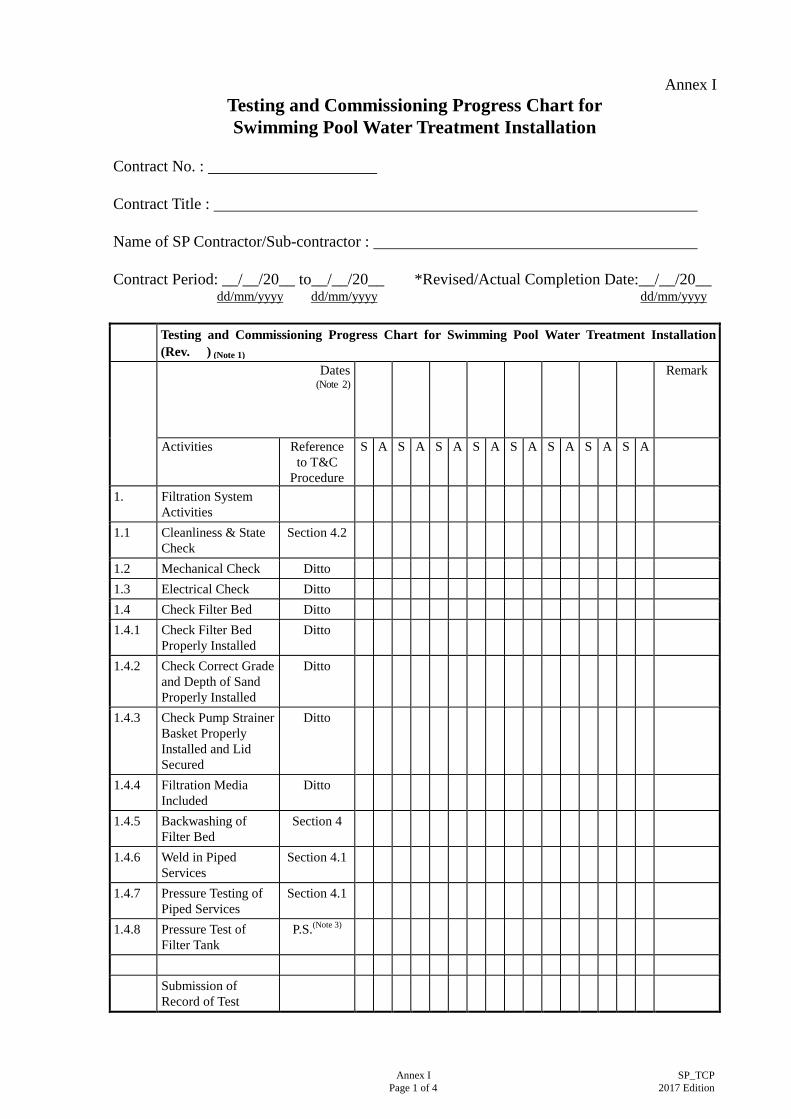
Testing and Commissioning Progress Chart for Swimming Pool Water Treatment Installation
Contract No. : Contract Title : Name of SP Contractor/Sub-contractor : Contract Period: __/__/20__ to__/__/20__ *Revised/Actual Completion Date:__/__/20__ dd/mm/yyyy dd/mm/yyyy dd/mm/yyyy Testing and Commissioning Progress Chart for Swimming Pool Water Treatment Installation
(Rev. ) (Note 1) Dates
(Note 2)
Remark
Activities Reference to T&C
Procedure
S A S A S A S A S A S A S A S A
1. Filtration System Activities
1.1 Cleanliness & State Check
Section 4.2
1.2 Mechanical Check Ditto 1.3 Electrical Check Ditto 1.4 Check Filter Bed Ditto 1.4.1 Check Filter Bed
Properly Installed Ditto
1.4.2 Check Correct Grade and Depth of Sand Properly Installed
Ditto
1.4.3 Check Pump Strainer Basket Properly Installed and Lid Secured
Ditto
1.4.4 Filtration Media Included
Ditto
1.4.5 Backwashing of Filter Bed
Section 4
1.4.6 Weld in Piped Services
Section 4.1
1.4.7 Pressure Testing of Piped Services
Section 4.1
1.4.8 Pressure Test of Filter Tank
P.S.(Note 3)
Submission of
Record of Test
Annex I
Annex I SP_TCP Page 2 of 4 2017 Edition
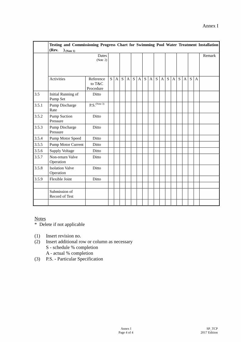
Testing and Commissioning Progress Chart for Swimming Pool Water Treatment Installation
Testing and Commissioning Progress Chart for Swimming Pool Water Treatment Installation
(Rev. ) (Note 1) Dates
(Note 2)
Remark
Activities Reference to T&C
Procedure
S A S A S A S A S A S A S A S A
3.5 Initial Running of Pump Set
Ditto
3.5.1 Pump Discharge Rate
P.S.(Note 3)
3.5.2 Pump Suction Pressure
Ditto
3.5.3 Pump Discharge Pressure
Ditto
3.5.4 Pump Motor Speed Ditto 3.5.5 Pump Motor Current Ditto 3.5.6 Supply Voltage Ditto 3.5.7 Non-return Valve
Operation Ditto
3.5.8 Isolation Valve Operation
Ditto
3.5.9 Flexible Joint Ditto Submission of
Record of Test
Notes * Delete if not applicable (1) Insert revision no. (2) Insert additional row or column as necessary S - schedule % completion A - actual % completion (3) P.S. - Particular Specification
Annex II
Annex II SP_TCP Page 1 of 11 2017 Edition
Testing and Commissioning Certificate on Swimming Pool Water Treatment Installation
Part 1: Details of Project
1.1 Project title (with location): ___________________________________
1.5 Date of Test: _______________________________________________
1.6 Name of PBSE: ____________________________________________
1.7 Name of *PBSI: ____________________________________________
Part 2: Declaration
2.1 I certify that the Swimming Pool Water Treatment Installation as specified in the *Contract/Sub-contract/Quotation at the above location has been inspected, tested and commissioned in accordance with this Testing and Commissioning (T&C) Procedure (Note 1) and/or any other procedure(s) as agreed between the PBSE and the SP Contractor. The results are satisfactory in the aspects as mentioned in Part 3 and/or as recorded in Part 4 of this Certificate, except as indicated in the COMMENTS item(s).
2.2 I also certify that site tests have been performed in accordance with the
requirements set out in this T&C Procedure and that the results are satisfactory. A record of the tests has been prepared and submitted to the PBSE.
Name of SP Contractor’s Representative: ________________________________________
Signature: ______________________________________
Designation / Post of SP Contractor’s Representative: ________________________________________
Date signed: ______________________________________
Name and Stamp of SP Contractor: ________________________________________
Notes (1) “T&C Procedure” refers to the Testing and Commissioning Procedure for Swimming Pool Water
Treatment Installation.
(2) The SP Contractor’s Representative signing this Certificate must be a person or representative authorised by the SP Contractor.
* Delete if not applicable
Annex II
Tested / Checked by : (Name of SP Contractor’s Representative)
Signature - Post :
Tel. No. :
( ) Date : Witnessed by : (Name(s) of *PBSE/PBSI)
Signature - Post :
Tel. No. :
( ) Date : Annex II SP_TCP
Page 2 of 11 2017 Edition
Items tested/
checked by: SP Contractor
Items witnessed by:
PBSE/PBSI
Part 3: Items Inspected and Tested
3.1 General Requirement as indicated in the T&C Procedure have been complied
*Yes/No *Yes/No
3.2 Pre-commissioning Checks
3.2.1 Water Distribution System 3.2.1.1 The system has been properly cleaned, flushed and
filled with water. *Yes/No *Yes/No
3.2.1.2 The equipment associated with the system has
undergone mechanical and electrical checks and the results are satisfactory.
*Yes/No *Yes/No
3.2.2 Filtration System 3.2.2.1 The filter beds have been properly installed and are
level. *Yes/No *Yes/No
3.2.2.2 Correct grade and depth of sand has been installed
according to the manufacturer’s recommendation. *Yes/No *Yes/No
3.2.2.3 The pump strainer basket has been properly closed and
the lid secured. *Yes/No *Yes/No
3.2.2.4 All inspection doors have been properly closed and all
valves have been set in their proper positions. *Yes/No *Yes/No
3.3 Setting to Work & Balancing
3.3.1 Water Distribution System
3.3.1.1 The water pumps have been commissioned in accordance with this T&C Procedure and the pumps are operating satisfactorily.
*Yes/No *Yes/No
Annex II
Tested / Checked by : (Name of SP Contractor’s Representative)
Signature - Post :
Tel. No. :
( ) Date : Witnessed by : (Name(s) of *PBSE/PBSI)
Signature - Post :
Tel. No. :
( ) Date : Annex II SP_TCP
Page 3 of 11 2017 Edition
Items tested/
checked by: SP Contractor
Items witnessed by:
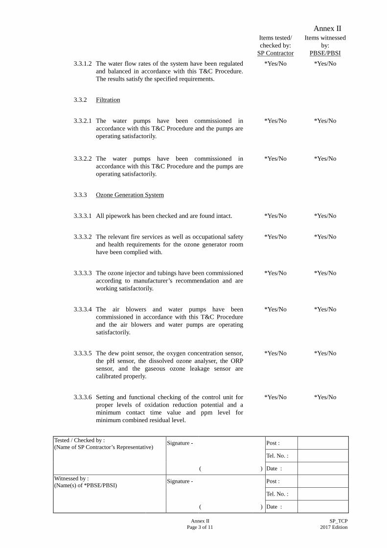
PBSE/PBSI 3.3.1.2 The water flow rates of the system have been regulated
and balanced in accordance with this T&C Procedure. The results satisfy the specified requirements.
*Yes/No *Yes/No
3.3.2 Filtration
3.3.2.1 The water pumps have been commissioned in
accordance with this T&C Procedure and the pumps are operating satisfactorily.
*Yes/No *Yes/No
3.3.2.2 The water pumps have been commissioned in accordance with this T&C Procedure and the pumps are operating satisfactorily.
*Yes/No *Yes/No
3.3.3 Ozone Generation System 3.3.3.1 All pipework has been checked and are found intact. *Yes/No *Yes/No 3.3.3.2 The relevant fire services as well as occupational safety
and health requirements for the ozone generator room have been complied with.
*Yes/No *Yes/No
3.3.3.3 The ozone injector and tubings have been commissioned
according to manufacturer’s recommendation and are working satisfactorily.
*Yes/No *Yes/No
3.3.3.4 The air blowers and water pumps have been
commissioned in accordance with this T&C Procedure and the air blowers and water pumps are operating satisfactorily.
*Yes/No *Yes/No
3.3.3.5 The dew point sensor, the oxygen concentration sensor,
the pH sensor, the dissolved ozone analyser, the ORP sensor, and the gaseous ozone leakage sensor are calibrated properly.
*Yes/No *Yes/No
3.3.3.6 Setting and functional checking of the control unit for
proper levels of oxidation reduction potential and a minimum contact time value and ppm level for minimum combined residual level.
*Yes/No *Yes/No
Annex II
Tested / Checked by : (Name of SP Contractor’s Representative)
Signature - Post :
Tel. No. :
( ) Date : Witnessed by : (Name(s) of *PBSE/PBSI)
Signature - Post :
Tel. No. :
( ) Date : Annex II SP_TCP
Page 4 of 11 2017 Edition
Items tested/
checked by: SP Contractor
Items witnessed by:
PBSE/PBSI 3.3.3.7 Turn on the ozone injector and the power supply for
testing the equipment is operating satisfactorily. *Yes/No *Yes/No
3.3.3.8 The pool water has been tested for proper ozone
concentration, oxidation reduction potential and pH level.
3.3.4.1 All pipework has been checked and are found intact. *Yes/No *Yes/No 3.3.4.2 The relevant fire services as well as occupational safety
and health requirements for the electrolytic cell room have been complied with.
*Yes/No *Yes/No
3.3.4.3 The chlorine solution supply line has been
commissioned according to manufacturer’s recommendation and is working satisfactorily.
*Yes/No *Yes/No
3.3.4.4 The air (hydrogen) blowers and water pumps have been
commissioned in accordance with this T&C Procedure and the air blowers and water pumps are operating satisfactorily.
*Yes/No *Yes/No
3.3.4.5 The liquid level sensors, the brine concentration sensor,
the pH sensor, the free chlorine (mixed oxidant) analyser, the ORP sensor, and the gaseous hydrogen leakage sensor, are calibrated properly.
*Yes/No *Yes/No
3.3.4.6 Setting and functional checking of the control unit for
proper levels for breakpoint chlorination condition and for minimum combined residual level and pH value.
*Yes/No *Yes/No
3.3.4.7 Turn on the power supply for testing and the equipment
is operating satisfactorily. *Yes/No *Yes/No
3.3.4.8 The pool water has been tested for proper residual
chlorine (or mixed oxidant) level and pH level. *Yes/No *Yes/No
Annex II
Tested / Checked by : (Name of SP Contractor’s Representative)
Signature - Post :
Tel. No. :
( ) Date : Witnessed by : (Name(s) of *PBSE/PBSI)
Signature - Post :
Tel. No. :
( ) Date : Annex II SP_TCP
Page 5 of 11 2017 Edition
Items tested/
checked by: SP Contractor
Items witnessed by:
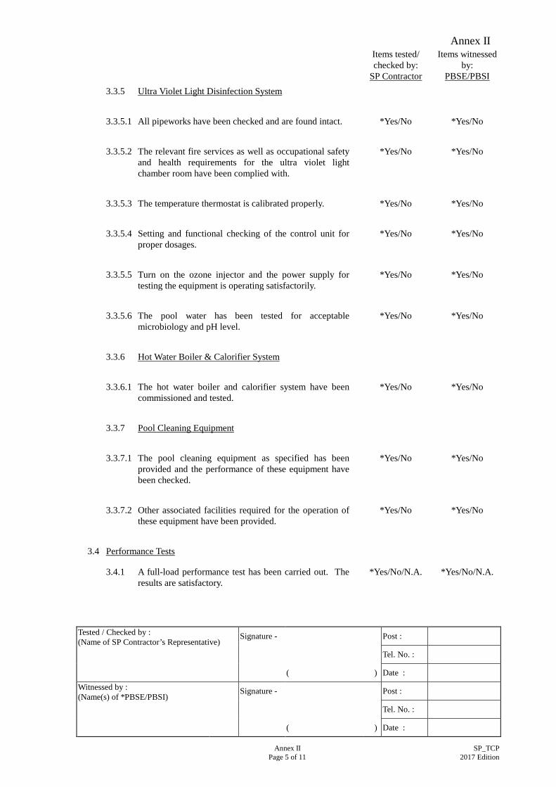
PBSE/PBSI 3.3.5 Ultra Violet Light Disinfection System 3.3.5.1 All pipeworks have been checked and are found intact. *Yes/No *Yes/No 3.3.5.2 The relevant fire services as well as occupational safety
and health requirements for the ultra violet light chamber room have been complied with.
*Yes/No *Yes/No
3.3.5.3 The temperature thermostat is calibrated properly. *Yes/No *Yes/No 3.3.5.4 Setting and functional checking of the control unit for
proper dosages. *Yes/No *Yes/No
3.3.5.5 Turn on the ozone injector and the power supply for
testing the equipment is operating satisfactorily. *Yes/No *Yes/No
3.3.5.6 The pool water has been tested for acceptable
microbiology and pH level. *Yes/No *Yes/No
3.3.6 Hot Water Boiler & Calorifier System 3.3.6.1 The hot water boiler and calorifier system have been
commissioned and tested. *Yes/No *Yes/No
3.3.7 Pool Cleaning Equipment 3.3.7.1 The pool cleaning equipment as specified has been
provided and the performance of these equipment have been checked.
*Yes/No *Yes/No
3.3.7.2 Other associated facilities required for the operation of
these equipment have been provided. *Yes/No *Yes/No
3.4 Performance Tests
3.4.1 A full-load performance test has been carried out. The results are satisfactory.
*Yes/No/N.A. *Yes/No/N.A.
Annex II
Tested / Checked by : (Name of SP Contractor’s Representative)
Signature - Post :
Tel. No. :
( ) Date : Witnessed by : (Name(s) of *PBSE/PBSI)
Signature - Post :
Tel. No. :
( ) Date : Annex II SP_TCP
Page 6 of 11 2017 Edition
Items tested/
checked by: SP Contractor
Items witnessed by:
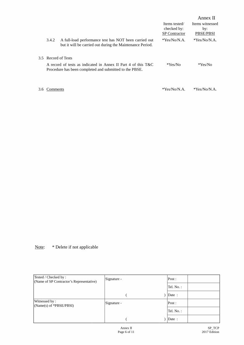
PBSE/PBSI 3.4.2 A full-load performance test has NOT been carried out
but it will be carried out during the Maintenance Period. *Yes/No/N.A. *Yes/No/N.A.
3.5 Record of Tests A record of tests as indicated in Annex II Part 4 of this T&C
Procedure has been completed and submitted to the PBSE. *Yes/No *Yes/No
3.6 Comments *Yes/No/N.A. *Yes/No/N.A.
Note: * Delete if not applicable
Annex II
Tested / Checked by : (Name of SP Contractor’s Representative)
Signature - Post :
Tel. No. :
( ) Date : Witnessed by : (Name(s) of *PBSE/PBSI)
Signature - Post :
Tel. No. :
( ) Date : Annex II SP_TCP
Page 7 of 11 2017 Edition
Part 4 : Test Record attached to the Test Certificate
4.1 Test Data
4.1.1 Plant performance can be substantiated only when the test data has been recorded and validated against the design data. Proforma for recording such data can be found in the succeeding pages and these should be properly filled in before submission to the PBSE with any relevant comments related to site conditions.
4.1.2 Water Distribution System 4.1.2.1 Pumps
Location No. Design Measured
Volume (1/s) No Flow Head (kPa) Full Flow Discharge Head
(kPa)
Full Flow Suction Pressure
(kPa)
Full Flow Differential
(kPa)
Motor Type Motor Speed (rev/s) Motor Full-load Current
(amperes & volt)
Annex II
Tested / Checked by : (Name of SP Contractor’s Representative)
Signature - Post :
Tel. No. :
( ) Date : Witnessed by : (Name(s) of *PBSE/PBSI)
Signature - Post :
Tel. No. :
( ) Date : Annex II SP_TCP
Page 8 of 11 2017 Edition
4.1.2.2 Filter Beds (Sand)
Location No. Design Measured Filter Area (m2) Entering Water Pressure (kPa) Leaving Water Pressure (kPa) Differential Pressure (kPa) Water Quantity (1/m2) Equipment Full-load Current
(amperes & volt)
4.1.2.3 Water Distribution in Pipeworks
Use the water schematic diagram indicating the design figures for flow rate, measure the temperature and insert the measured figures in brackets.
4.1.3 Chemical Metering Pumps
Location No. Design Measured Fluid Handling Manufacturer Model/Type Chemical Feed Rate (1/s) Automatic Timer Setting Equipment Full-load Current
(amperes & volt)
4.1.4 Ozonators
Location No. Design Measured Manufacturer Model Type Ozone Generation Rate
(g/s)
Ozone Concentration
(ppm)
Equipment Full-load Current
(amperes & volt)
Annex II
Tested / Checked by : (Name of SP Contractor’s Representative)
Location No. Design Measured Manufacturer Model Type Disinfectant Feed Rate
(1/s)
Disinfectant Concentration
(ppm)
Equipment Full-load Current
(amperes & volt)
4.1.6 UV Light Disinfection Systems
Location No. Design Measured Manufacturer Model Type Water Feed Rate (1/s) UV Dosage Rate (MWs/c m2) Equipment Full-load Current
(amperes & volt)
Annex II
Tested / Checked by : (Name of SP Contractor’s Representative)
Signature - Post :
Tel. No. :
( ) Date : Witnessed by : (Name(s) of *PBSE/PBSI)
Signature - Post :
Tel. No. :
( ) Date : Annex II SP_TCP
Page 10 of 11 2017 Edition
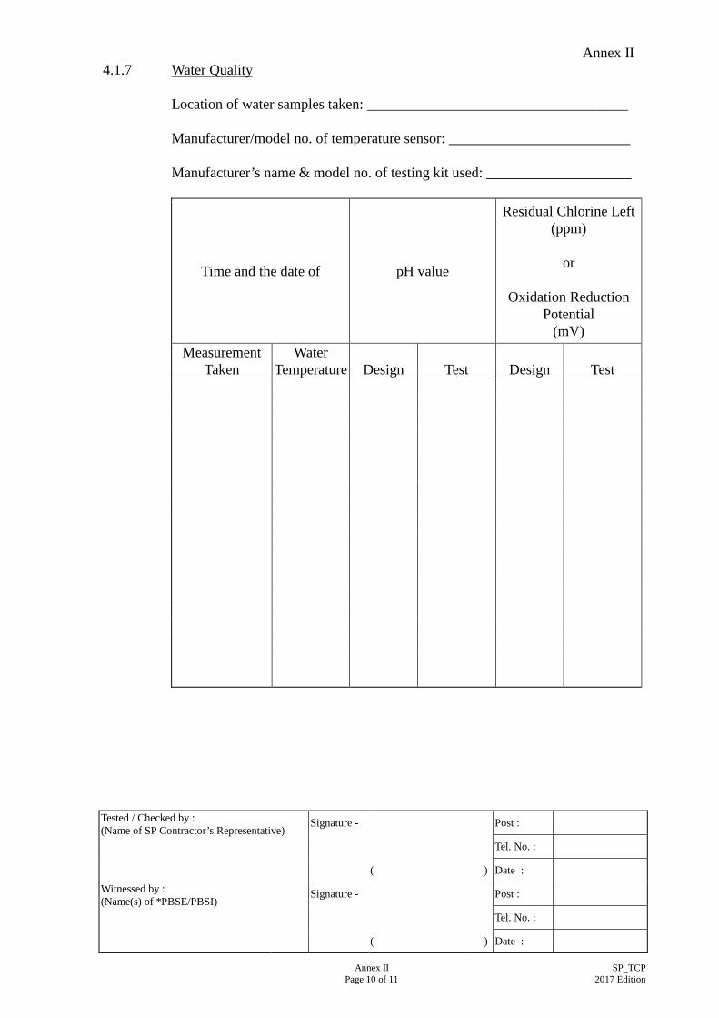
4.1.7 Water Quality
Location of water samples taken: ____________________________________ Manufacturer/model no. of temperature sensor: _________________________ Manufacturer’s name & model no. of testing kit used: ____________________
Time and the date of pH value
Residual Chlorine Left (ppm)
or
Oxidation Reduction Potential
(mV) Measurement
Taken Water
Temperature
Design
Test
Design
Test
Annex II
Tested / Checked by : (Name of SP Contractor’s Representative)
Signature - Post :
Tel. No. :
( ) Date : Witnessed by : (Name(s) of *PBSE/PBSI)
Signature - Post :
Tel. No. :
( ) Date : Annex II SP_TCP
Page 11 of 11 2017 Edition
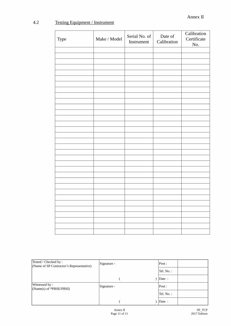
4.2 Testing Equipment / Instrument
Type Make / Model Serial No. of Instrument
Date of Calibration
Calibration Certificate
No.
Annex III
Annex III SP_TCP Page 1 of 1 2017 Edition
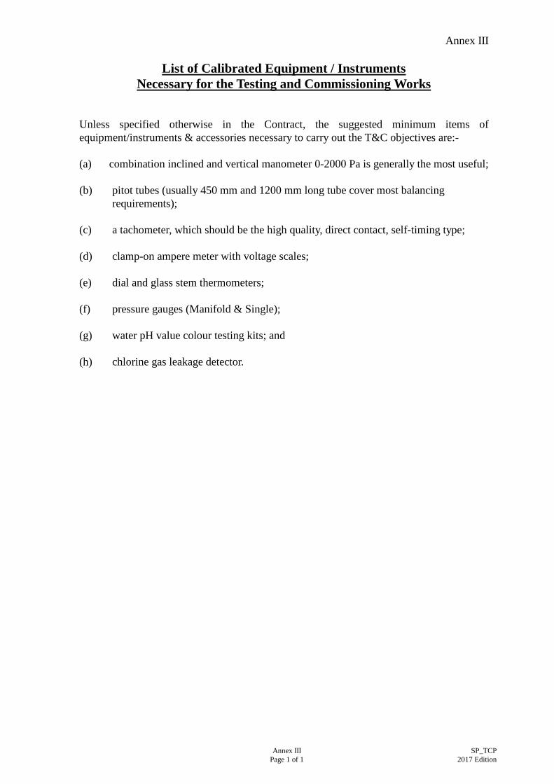
List of Calibrated Equipment / Instruments
Necessary for the Testing and Commissioning Works
Unless specified otherwise in the Contract, the suggested minimum items of equipment/instruments & accessories necessary to carry out the T&C objectives are:- (a) combination inclined and vertical manometer 0-2000 Pa is generally the most useful; (b) pitot tubes (usually 450 mm and 1200 mm long tube cover most balancing
requirements); (c) a tachometer, which should be the high quality, direct contact, self-timing type; (d) clamp-on ampere meter with voltage scales; (e) dial and glass stem thermometers; (f) pressure gauges (Manifold & Single); (g) water pH value colour testing kits; and (h) chlorine gas leakage detector.