Testing Procedures Drilling and Sampling: Standard penetration tests (SPT) were conducted for every ten feet of boring advancement. SPT tests were conducted in accordance with ASTM D1586, using a 140 pound hammer falling a distance of 2.5 feet. “Undisturbed” soil samples were generally obtained on a ten-foot interval midway between the SPT tests. The undisturbed samples were retrieved using a modified California sampler (split spoon sampler with brass rings, D o =2.5 in, D I =1.94 in) for relatively undisturbed soil samples. The soil samples recovered within the brass rings were sealed with plastic caps/tapes and transported to Caltrans laboratory facilities for testing. Rock core samples were taken using a 4 in diameter diamond impregnated drilling bit, where 2.25 in core samples were taken from the core barrel, logged in the field, and placed in core boxes with labeled depths. Note: Please refer to Table 2 for a list of completed borings. Cone Penetration Test: The CPT soundings were performed according to ASTM D5778- 95. The Caltrans CPT apparatus employed is a truck-mounted, Hogentogler electric cone penetration testing system. CPT soundings were performed at selected locations, as shown in Table 2, to depths from 0.79 to 35 feet below ground surface. All penetrations were terminated either at required depth, or when the CPT penetrating cone was stopped due to resistance levels greater than CPT operating specifications (Tip Resistance at 47826 kPa /500tsf). Laboratory Testing: The laboratory testing program consisted of moisture-density determinations (California Test Method (CTM 226)), grain-size distribution (CTM 203), direct-shear (CTM 222), consolidation/collapse potential testing of undisturbed soil specimens (CTM 219), compaction tests (CTM 216), and corrosion tests (CTM 532, 417, 422) of disturbed bulk samples (see Section 13). The results of Laboratory testing are presented in Appendix VI. The Soil Collapse Test is done as a part of the consolidation testing under CTM 219. The vertical pressure on the soil specimen is increased to 100kPa (or 1tsf/2000psf). At this vertical pressure, distilled water is added to the oedometer to measure the amount of one- dimensional collapse of soil specimen. The collapse potential is defined as the change in height of specimen due to inundation divided by the initial height of the specimen. For compaction testing, instead of adding and subtracting moisture from the soil specimen at field moisture condition, the soil samples are dried, and water is added at 2% increment for compaction to determine the maximum dry density/optimum moisture content.
Transcript
Testing Procedures
Drilling and Sampling: Standard penetration tests (SPT) were conducted for every ten feet of boring advancement. SPT tests were conducted in accordance with ASTM D1586, using a 140 pound hammer falling a distance of 2.5 feet. “Undisturbed” soil samples were generally obtained on a ten-foot interval midway between the SPT tests. The undisturbed samples were retrieved using a modified California sampler (split spoon sampler with brass rings, Do=2.5 in, DI=1.94 in) for relatively undisturbed soil samples. The soil samples recovered within the brass rings were sealed with plastic caps/tapes and transported to Caltrans laboratory facilities for testing. Rock core samples were taken using a 4 in diameter diamond impregnated drilling bit, where 2.25 in core samples were taken from the core barrel, logged in the field, and placed in core boxes with labeled depths. Note: Please refer to Table 2 for a list of completed borings. Cone Penetration Test: The CPT soundings were performed according to ASTM D5778-95. The Caltrans CPT apparatus employed is a truck-mounted, Hogentogler electric cone penetration testing system. CPT soundings were performed at selected locations, as shown in Table 2, to depths from 0.79 to 35 feet below ground surface. All penetrations were terminated either at required depth, or when the CPT penetrating cone was stopped due to resistance levels greater than CPT operating specifications (Tip Resistance at 47826 kPa /500tsf). Laboratory Testing: The laboratory testing program consisted of moisture-density determinations (California Test Method (CTM 226)), grain-size distribution (CTM 203), direct-shear (CTM 222), consolidation/collapse potential testing of undisturbed soil specimens (CTM 219), compaction tests (CTM 216), and corrosion tests (CTM 532, 417, 422) of disturbed bulk samples (see Section 13). The results of Laboratory testing are presented in Appendix VI. The Soil Collapse Test is done as a part of the consolidation testing under CTM 219. The vertical pressure on the soil specimen is increased to 100kPa (or 1tsf/2000psf). At this vertical pressure, distilled water is added to the oedometer to measure the amount of one-dimensional collapse of soil specimen. The collapse potential is defined as the change in height of specimen due to inundation divided by the initial height of the specimen. For compaction testing, instead of adding and subtracting moisture from the soil specimen at field moisture condition, the soil samples are dried, and water is added at 2% increment for compaction to determine the maximum dry density/optimum moisture content.
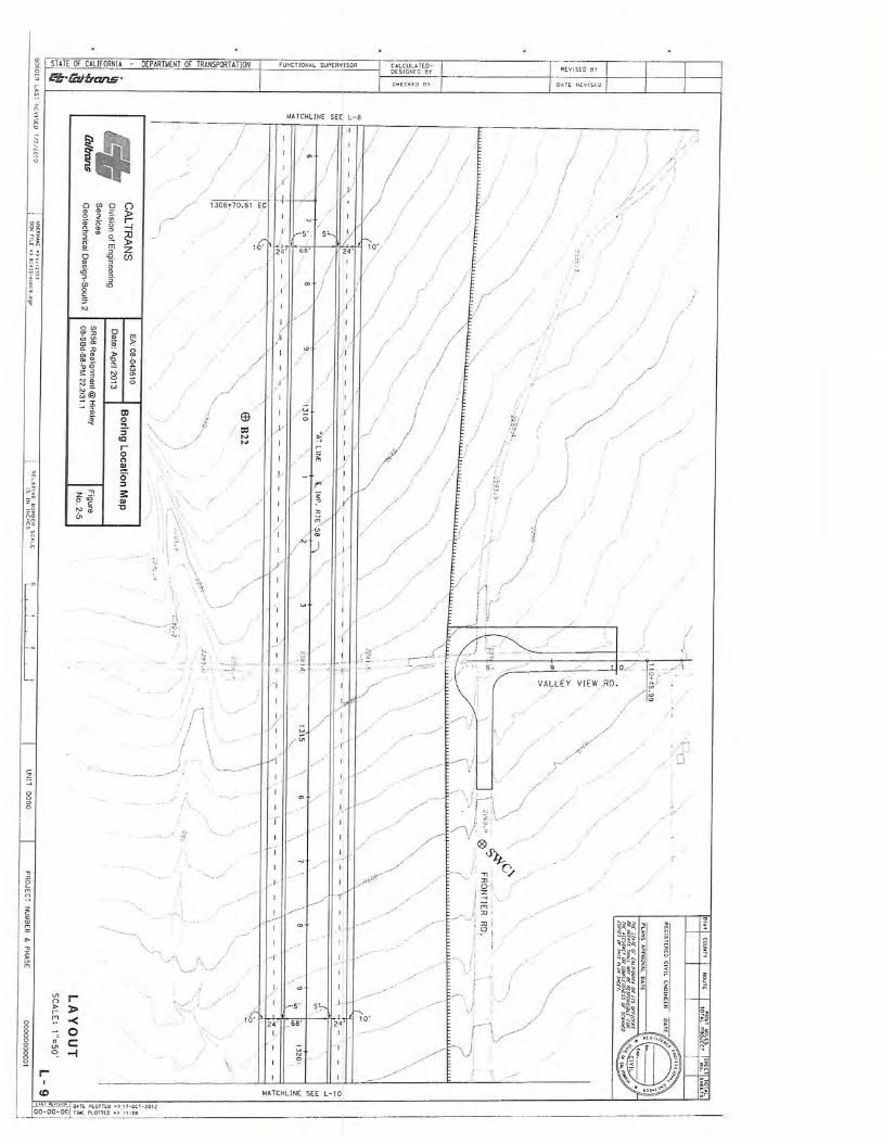
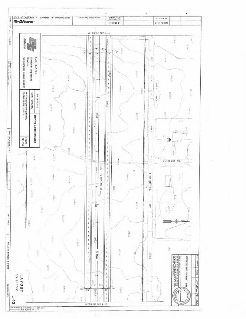
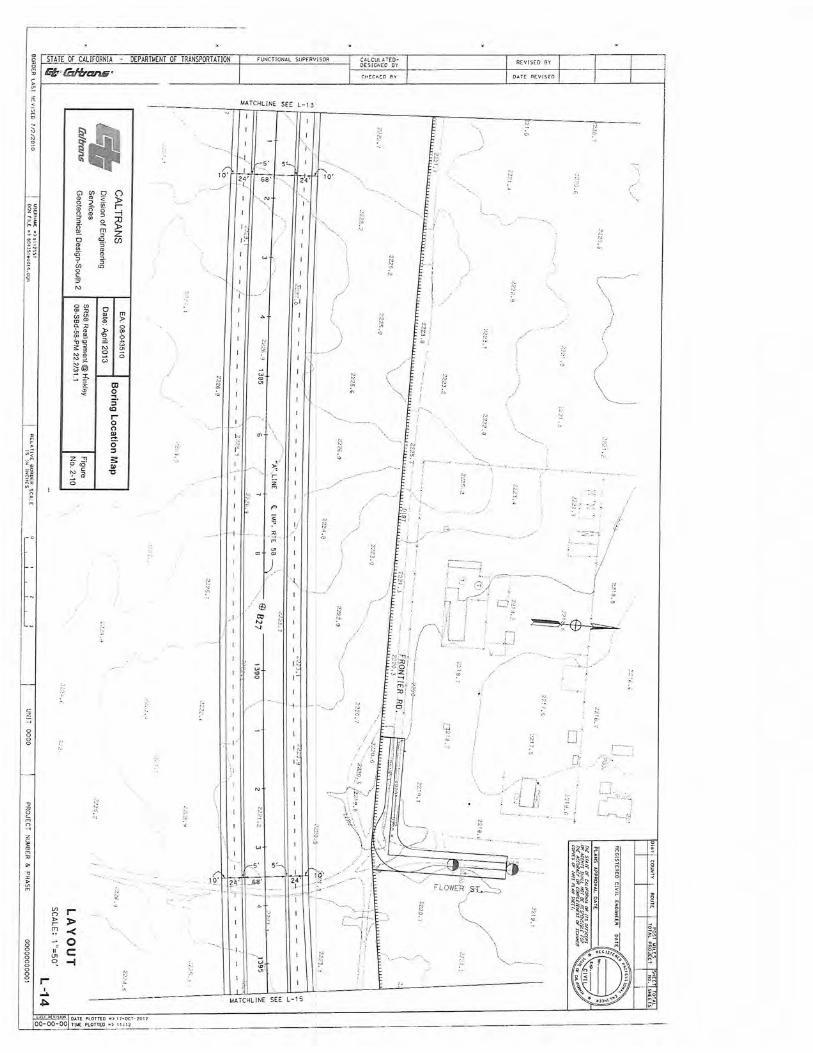
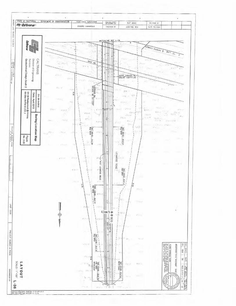
Table 2. Summary of Completed Boring Information (08-SBd-58-PM 22.2/31.1, EA: 08-043510)
Boring Number Location Equipment Soil Exploration Method Depth of boring