35
Testing Real-Time Embedded Software using UPPAAL-TRON An Industrial Case Study Kim G. Larsen Marius Mikucionis Brian Nielsen Arne Skou PRESENTED BY MOHAMMAD SALEEM

Testing Real-Time Embedded Software using UPPAAL-TRON
An Industrial Case StudyKim G. Larsen Marius Mikucionis Brian Nielsen Arne Skou
P R E S E N T E D B Y
MOHAMMAD SALEEM
OUTLINES
RESEARCH GOAL
INTRODUCTION
TESTING FRAMEWORK
THE DANFOSS EKC-201 REFRIGERATION CONTROLLER
COMPONENT MODELING AND REVERSE ENGINEERING
QUANTITATIVE EVALUATION
CONCLUSIONS
RESEARCH GOAL
The work presented in this paper performs real-time online black-box testing (both real-time stimulation and conformance checking) for a real industrial embedded device consisting of hardware and software to evaluate the feasibility of the technique.
INTRODUCTION
UPPAAL is a mature integrated tool environment for modeling, verification, simulation, and testing of real-time systems modeled as networks of timed automata.
UPPAAL-TRON (TRON for short) is a recent addition to the UPPAAL environment. It performs model-based black-box conformance testing of the real-time constraints of embedded systems.
- TRON is an online testing tool which means that it, at the same time, both generates and executes tests event-by-event in real-time.
- Applying TRON on small examples has shown promising error detection capability and performance.

INTRODUCTION
-TRON replaces the environment of the IUT.
-TRON performs two logical functions, stimulation and monitoring.
-TRON stimulates the IUT with input that is deemed relevant by the model. At the same time it monitors the outputs and checks the conformance of these against the behavior specified in the model.
-TRON computes the set of states that the model can possibly occupy after the timed trace observed so far.

TESTING FRAMEWORK- A major development task is to ensure that an embedded system
works correctly in its real operating environment.
- check whether the behavior of the IUT is correct according to its
specification under assumptions about the behavior of the actual
environment in which it is supposed to work.
- TRON replaces the environment of the IUT, and based on the timed sequence of input and output actions performed so far, it stimulates the IUT with input that is deemed relevant by the environment part of the model.
- The adapter is an IUT specific hardware/software component that connects TRON to the IUT.

TESTING FRAMEWORKRelativized Conformance Testing
- After executing any timed input/ output trace σ that is possible in the composition of the system specification s and environment specification e, the implementation i in environment e may only produce outputs and timed delays which are included in the specification s under environment e.

TESTING FRAMEWORKTimed Automata
- They assume that a formal specification can be modeled as a network of timed
automata.
- UPPAAL automaton of a simple cooling controller Cr where x is real-valued clock and r is an integer constant. Its goal is to control and keep the room temperature in Med range.
- In location off the automaton reacts non-deterministically to input Med: Cr may choose either to take a loop transition and stay in location off or move to location up.
-There are two sources of non-determinism in timed automata: 1) in the timing (tolerances) of actions as allowed by location invariants and guards, and 2) in the possible state after an action.
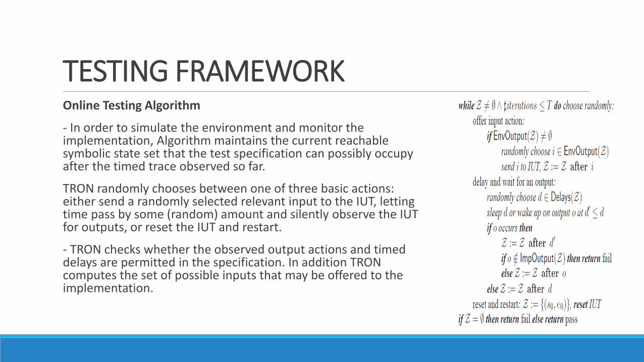
TESTING FRAMEWORKOnline Testing Algorithm
- In order to simulate the environment and monitor the implementation, Algorithm maintains the current reachable symbolic state set that the test specification can possibly occupy after the timed trace observed so far.
TRON randomly chooses between one of three basic actions: either send a randomly selected relevant input to the IUT, letting time pass by some (random) amount and silently observe the IUT for outputs, or reset the IUT and restart.
- TRON checks whether the observed output actions and timed delays are permitted in the specification. In addition TRON computes the set of possible inputs that may be offered to the implementation.

THE DANFOSS EKC-201 REFRIGERATIONCONTROLLERControl Objective
- The main control objective is to keep the refrigerator room air temperature at a user defined set-point by switching a compressor on and off.
- It monitors the actual room temperature, and sounds an alarm if the temperature is too high (or too low) for too long a period.

THE DANFOSS EKC-201 REFRIGERATIONCONTROLLERControl Objective
- The room temperature Tn calculated by the EKC by periodically sampling (around 1.2 sec.) the air temperature sensor such that a new sample T is weighted by 20% and the old average Tn−1 by 80%:

THE DANFOSS EKC-201 REFRIGERATIONCONTROLLERModel Structure
The Temperature Measurement component periodically samples the temperature sensor and calculates a new estimated room air temperature.

THE DANFOSS EKC-201 REFRIGERATIONCONTROLLERModel Structure
The Compressor component controls the compressor relay based on the estimated room temperature, alarm and defrost status.

THE DANFOSS EKC-201 REFRIGERATIONCONTROLLERModel Structure
The High Temperature Alarm component monitors the alarm state of the EKC, and triggers the alarm relay if the temperature is too high for too long.

THE DANFOSS EKC-201 REFRIGERATIONCONTROLLERModel Structure
The Defrost component controls the events that must take place during a defrost cycle.

THE DANFOSS EKC-201 REFRIGERATIONCONTROLLERModel Structure
The Defrost component controls the events that must take place during a defrost cycle.

THE DANFOSS EKC-201 REFRIGERATIONCONTROLLERModel Structure
The Temperature Generator is a part of the environment that simulates the variation in room temperature, currently alternatingly increases the temperature linearly between minimum and maximum temperature, and the reverse.

THE DANFOSS EKC-201 REFRIGERATIONCONTROLLERModel Structure
Defrost Event Generator environment component randomly issues user initiated defrost start and stop commands.

COMPONENT MODELING ANDREVERSE ENGINEERING
In general the documentation was insufficient to build the model due to a lack of a detailed understanding of the knowledge of the problem domain and how previous generations of controllers worked.
The requirements specification did not state any timing tolerances, e.g, the allowed latency on compressor start and stop when the calculated temperature crosses the lower or higher thresholds.
Therefore the modeling involved a lot of experimentation to deduce the right model and time constraints, which to some extent best can be characterized as reverse engineering or model-learning.
COMPONENT MODELING ANDREVERSE ENGINEERING
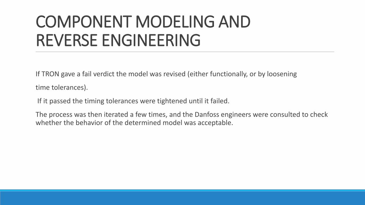
If TRON gave a fail verdict the model was revised (either functionally, or by loosening
time tolerances).
If it passed the timing tolerances were tightened until it failed.
The process was then iterated a few times, and the Danfoss engineers were consulted to check whether the behavior of the determined model was acceptable.

COMPONENT MODELING ANDREVERSE ENGINEERINGRoom Temperature Tracking
The requirements only requires a certain precision on the sampling accuracy of the temperature sensors (±0.5◦C) and a sensor sampling period of at most 2 seconds, and nothing about how frequently the temperature should be reevaluated.
This led to a series of tests where the temperature change rate, the sampling period, and temperature tolerance were changed to determine the best matching configuration.
- The model now uses a period of 1.2 seconds, and allows ± 2 seconds tolerance on compressor start/stop.

COMPONENT MODELING ANDREVERSE ENGINEERINGAlarm Monitoring
- Executing TRON using the first version of the high temperature alarm monitor caused TRON to give a fail-verdict: The EKC did not raise alarms as expected.
- The explanation given by Danfoss was that clearing the alarm only clears the alarm relay (stopping the alarm noise), not the alarm state which remains in effect until the temperature drops below the critical limit.
The model was then refined, and includes the noSound Displaying location.

COMPONENT MODELING ANDREVERSE ENGINEERINGAlarm Monitoring

COMPONENT MODELING ANDREVERSE ENGINEERINGDefrosting and Alarm Handling
After a defrost, the room temperature naturally risks being higher than the alarm limit, because cooling has been switched off during the defrost activity for an extended period of time. Therefore a high temperature alarm should be suppressed in this situation which can be done by configuring the EKC parameter alarmDelayAfterDefrost.
alarmDelayAfterDefrost replaces the original alarmDelay after a defrost until the temperature becomes below critical, after which the normal alarmDelay is used again.

COMPONENT MODELING ANDREVERSE ENGINEERINGDefrost Time Tolerance.
Another discrepancy TRON found was that defrosting started earlier than expected or was disengaged later. It turned out that the internal timer in the EKC responsible for controlling the defrost period has a very low precision (probably because defrosting is rare (e.g., once a day) and has along duration (lasts several hours)). The default tolerance used in the model on the relays thus had to be further relaxed.

QUANTITATIVE EVALUATION
Since TRON generate and execute tests in real-time the state-set must also be updated in real-time. Obviously, the model and the state-set size affects how much computation time this takes,
one might question whether doing this is feasible in practice?
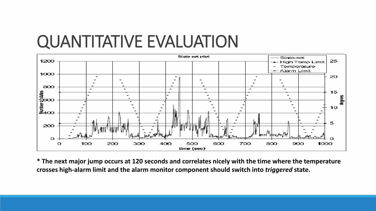
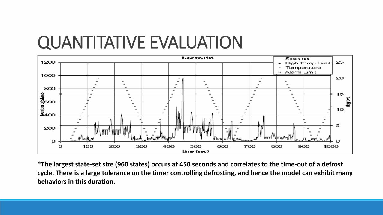
The evolution of the state-set size (number of symbolic states) for a sample test run is shown in the next figure.

QUANTITATIVE EVALUATION
*The first larger increase in state-set size occurs after 55 seconds. At this time the temperature crosses the limit where the compressor should switch on. But due to the timing tolerances, the model does not “know” if the compressor relay is in on-state or off-state, resulting in a larger state-set.

QUANTITATIVE EVALUATION
*The state-set size then decreases again, only to increase again at 93 seconds at which a manual defrost period is started.
QUANTITATIVE EVALUATION
* The next major jump occurs at 120 seconds and correlates nicely with the time where the temperature crosses high-alarm limit and the alarm monitor component should switch into triggered state.

QUANTITATIVE EVALUATION
*Similarly, 260 second into the run, the temperature drops below the threshold, and there is no uncertainty in the alarm state. The fluctuations inside this period is caused by a manually started and stopped defrost session.
QUANTITATIVE EVALUATION
*The largest state-set size (960 states) occurs at 450 seconds and correlates to the time-out of a defrost cycle. There is a large tolerance on the timer controlling defrosting, and hence the model can exhibit many behaviors in this duration.

QUANTITATIVE EVALUATIONThe state-set contains most often less than a few hundred states. Exploring these is unproblematic for a modern model-checking engine employed by TRON.
The cpu-time used to update the state-set for delay-actions for 5 test-runs of the model on a Dual Pentium Xeon 2.8 is shown in the next figure

QUANTITATIVE EVALUATIONUpdating medium sized state-sets with around 100 states requires only a few milli-seconds (ms) of cpu-time.
The largest encountered state-sets (around 3000 states) are very infrequent, and requires around 300 ms.
Real-time online testing thus appear feasible for a large range of embedded systems, but also that very non-deterministic model such as the EKC-model may limit the granularity of time constraints that can be checked in real-time.

CONCLUSIONS- TRON shows that it is possible to accurately model the behavior of EKC like devices as Timed Automata and use the resulting model as a test specification for online testing.
- The test shows many conflicts between the model and the implementation. Although many of these were caused by a wrong model due to incomplete requirements or mis-interpretations of the documentation, and not actual implementation errors.
- The work indicates that online testing seems an effective technique to find discrepancies between the expected model behavior and actual behavior of the implementation under test. Thus there are also reasons to believe that it is effective in detecting actual implementation errors.
- Real-time online testing appear feasible for a large range of embedded systems.