73
TFIR-31DMSeries Compact Fixed Mount Image Reader (Linear / 2D Scanner) OPERATION MANUAL TOHKEN CO.,LTD. 2nd Edition December 8, 2009

TFIR-31DMSeries
Compact Fixed Mount Image Reader (Linear / 2D Scanner)
OPERATION MANUAL
TOHKEN CO.,LTD.
2nd Edition December 8, 2009

[Memorandum]

- - I
Introduction Thank you for purchasing this product.
This manual explains the features of this product, operation, system configuration,
specifications, etc.
In order to use the product properly, please read this manual carefully.
When there is any problem during normal use, please document it carefully to be
reproduced by our support team.
The contents of this manual may be changed without a notice. Please check our website
for regular updates
Safety Notice
Please do not disassemble this product as this will void the warranty and might
cause an accident.
Please follow the warnings or notices of computers to be used with this
product.
Please stop using the product when there is smoke smell or strange sound to
avoid fire.
DO NOTDISASSENBLE
Reading
PULL OFF
- - II
CAUTION
Please do not use AC adapters other than the recommend AC power adaptor which is
described in the “unpacking the carton” section. Failure to do so might affect the
performance of the unit.
If the voltage or polarity used is different from the specification, it might cause product
failure and could be the cause of an accident.
Handling with care
CAUTION
About backup data
This product has a memory backup function. This backup can not guaranteed if repair,
reconstruction, and upgrade are performed on this Image Reader.
CAUTION
Please do not use this product at temperature or humidity ranges that are different from
the product specifications or under the direct sunshine.
CAUTION
This unit can be damaged in environment with corrosive gas.
CAUTION
Please do not drip water, moisture, oil, etc. on the unit.

- - III
CAUTION
When stain or dust is stuck on the reading window, please follow the following steps to
clean it:
- Wipe off stain lightly with cloth or swab (wet with alcohol)
- Wipe off again with the dry clothes.
DON NOT Wipe off with any chemicals.
CAUTION
This is a high-precision optical device. Avoid shocking the product such as fall.
Unpacking the product
After you open the shipping package containing the TFIR-31DM, take the following steps:
1- Check for damage that might occur during the shipping process. Report the damage
immediately to the carrier who delivered the shipment.
2- Save the shipping container for later storage or shipping.
3- Make sure everything ordered is present.
Items included with the product • AC Power Adaptor (Optional)
In case of purchase separately, select an adapter with output DC5V +/- 5% and more than
7W. Please confirm polarity and DC plug type as below.
Polarity:
DC plug type: EIAJ RC5320A Voltage Segment 2
Items included with the product Quantity
TFIR-31DM 1 unit
Operation Manual 1 copy

- - a
TABLE OF CONTENTS
INTRODUCTION.......................................................................................................................... I
SAFETY NOTICE ......................................................................................................................... I
HANDLING WITH CARE ...........................................................................................................II
UNPACKING THE PRODUCT................................................................................................. III
1.GETTING STARTED.................................................................................................................1 1.1 SUPPORTED BARCODES ........................................................................................................2 1.2 PICTURE TAKING ..................................................................................................................2 1.3 ORDERING INFORMATION.....................................................................................................3 1.4 HOW IT WORKS.....................................................................................................................4
2. OPERATION..............................................................................................................................5 2.1 BASIC OPERATION................................................................................................................5 2.2 READING OPERATION...........................................................................................................7 2.3 TRANSMITTING IMAGE DATA ...............................................................................................8 2.4 SWING MODE .......................................................................................................................8 2.5 USB INTERFACE ..................................................................................................................8
3. DESCRIPTION OF READING OPERATION.........................................................................9 3.1 NORMAL MODE ....................................................................................................................9 3.2 READ TIME OUT MODE ......................................................................................................12 3.3 EXTERNAL SYNC MODE.....................................................................................................15 3.4 CONTINUOUS READING MODE ...........................................................................................17 3.5 TEST MODE ........................................................................................................................17 3.6 SWING MODE .....................................................................................................................18 3.7 PRESET MODE....................................................................................................................19
1)Preset Mode 1................................................................................................................19 2)Preset Mode 2................................................................................................................19 3)Output the Preset status..............................................................................................21
3.8 DESCRIPTION OF DIAGNOSIS MODE....................................................................................22 1) Confirmation for Output of Reading statistics and Decoding Time ...........................22 2) Output decode time ........................................................................................................22 3) Output of total decoding time........................................................................................23 4) Symbol Code character System.....................................................................................23 5) Contrast Information .....................................................................................................24 6) Quality Information .......................................................................................................24 7) Output the coordinate of the symbol.............................................................................25
3.9 AUTO DETECTION MODE.....................................................................................................28 3.9.1 Overview ....................................................................................................................28 3.9.2 How to use..................................................................................................................29

- - b
3.9.3 Serial Command........................................................................................................30 3.9.4 Flow chart ..................................................................................................................32
4. SERIAL COMMAND...............................................................................................................33 4.1 TRANSMISSION SETTINGS ..................................................................................................33 4.2 READING SYMBOLS ............................................................................................................35 4.3 READING OPERATION (NORMAL OPERATION, ADJUSTMENT, DIAGNOSIS) .........................42 4.4 CAMERA CONTROL .............................................................................................................44 4.5 PRESET MODE SETTING.....................................................................................................45 4.6 REFERENCE SETTINGS.......................................................................................................45 4.7 SETTINGS FOR IMAGE OUTPUT ...........................................................................................46 4.8 IMAGE PREPROCESSING .....................................................................................................46 4.9 TABLE OF CHARACTER CODE ..............................................................................................48
5.SPECIFICATIONS...................................................................................................................49 5.1 GENERAL SPECIFICATIONS.................................................................................................49 5.2. FIELD OF VIEW AND HOW TO PLACE THE UNIT ..................................................................51 5.3 DIMENSIONS ......................................................................................................................52
5.3.1 F type (Front View)...............................................................................................52 5.3.2 F type (Front View)...............................................................................................53
5.5 INTERFACE.........................................................................................................................54
6. AUTOMATIC SETUP MODE.................................................................................................58 6.1 OVERVIEW..........................................................................................................................58 6.2 THE PROCEDURE OF AUTOMATIC CONFIGURATION ............................................................59
7.TROUBLESHOOTING ............................................................................................................61 7.1 THE UNIT DOES NOT WORK WHILE PUSHING THE READ TRIGGER SWITCH..........................61
Is power supply voltage within specification? ..................................................................61 Is power supply polarity correct?.......................................................................................61 Is the power rating of the power supply enough?.............................................................61 Is the format of serial command correct?..........................................................................61 Others..................................................................................................................................61
7.2 BARCODE CANNOT BE READ. .............................................................................................61 Is a code setup correct? ......................................................................................................61 Is reading distance suitable? .............................................................................................61 Is the surface of the code glossy?.......................................................................................61 Is the reading window clean? ............................................................................................62 Is the print quality of the code good? ................................................................................62
7.3 THE DATA DOES NOT TRANSMIT OR THE DATA ITSELF IS CORRUPTED. ...............................63 Is the setup with host computer correct?..........................................................................63 Do you set fixed digit for ITF.............................................................................................63

- - 1
1.Getting started
The TFIR-31DM is a compact high performance two-dimensional scanner that can read all
traditional 1D and 2D symbologies. Thanks to the special illumination, TFIR-31DM is
suitable for Direct Parts Marking application like laser marking on PCB and metal surface.
Leading the industry in cost-effectiveness, imaging performance and low power consumption,
the TFIR-31DM provides OEMs and Machine building companies with 1D & 2D barcode
scanning capability
The safe, high power LED-based illumination removes the risks involved with lasers without
sacrificing performance. The leading edge field of view provides end-users with freedom from
critical alignment which increases productivity.
. The TFIR-31DM is available in either serial or USB 1.1 interface. The TFIR-31DM has
RS-232C interface to connect to the host computer. The TFIR-31DMU has USB interface to
connect to a host computer that runs Windows2000/XP.

- - 2
1.1 Supported barcodes
The unit can read the following symbols:
1D bar codes:
Code39
Code128
Codabar
ITF (interleaved 2 of 5)
JAN/EAN/UPC
RSS
Code93
2D codes:
Data Matrix (ECC200)
QR Code
Micro QR
PDF 417
Micro PDF
Mxi Code
Composite
1.2 Picture taking
The TFIR-31DM can take 24bit color and Grey scale pictures for example signature capture.

- - 3
1.3 Ordering information
TFIR-31DM U F - X
1. Model name
2. Interface
If “U” follows “TFIR-31DM” , the scanner has USB interface.
And if there is no “U”, its interface is RS232C.
3. “F” or “S”
These are the position of the reading window. “F” means FRONT and “S” means
SIDE. “F” or “S”
4. Options
Cable modification etc.
According to this rule, there are 4 types of TFIR-31DM family.
・ TFIR-31DM-F
・ TFIR-31DM-S
・ TFIR-31DMU-F
・ TFIR-31DMU-S
1 2 3 4

- - 4
1.4 How it works
• Status LED
The status LED lights up either GREEN or RED depending on the operation:
- GREEN light indicates the completion of successful decoding of a symbol.
- Flashing GREEN light indicates the image data transmission in progress.
- RED light indicates the failure of decoding.
• Triggering Switch
This switch is used to initiate the read and decode of a symbol.
• Connecting Cable
- TFIR-31DM: RS-232C
When connecting to a host computer, a cable with D-sub 9Pins connector should be
utilized.
For supplying the power to the unit, the AC power adapter should be plugged into its
mating receptacle on the RS232 connector housing next to the D-sub 9Pins connector.
- TFIR-31DMU: USB
The unit is supplied its power through USB cable via host computer.
- - 5
2. Operation 2.1 Basic Operation
(1) When the power is turned on, LED A, B, C and D turn on simultaneously. After all of them turn
off, only LED B start blinking.
(2) Then two aiming beam indicate where the unit is seeing, where is the center of field of view.
(3) When SYNC is on, the TFIR captures an image and starts decoding the symbol.
The input SYNC can be done through:
- Soft trigger (serial command)
- “Read” button
- SYNC signal input
(4) After successful reading, decoded data is sent by serial interface.
(5) After failing to read:
* The buzzer remains silent.
* Error signal is sent by serial interface.
(6) Back to step (2)
- - 6
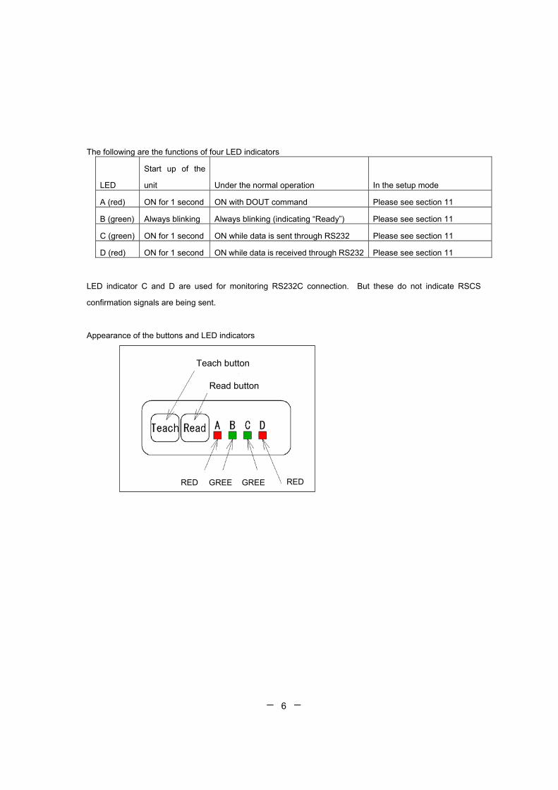
The following are the functions of four LED indicators
LED
Start up of the
unit Under the normal operation In the setup mode
A (red) ON for 1 second ON with DOUT command Please see section 11
B (green) Always blinking Always blinking (indicating “Ready”) Please see section 11
C (green) ON for 1 second ON while data is sent through RS232 Please see section 11
D (red) ON for 1 second ON while data is received through RS232 Please see section 11
LED indicator C and D are used for monitoring RS232C connection. But these do not indicate RSCS
confirmation signals are being sent.
Appearance of the buttons and LED indicators
Teach button
Read button
RED REDGREE GREE
- - 7
2.2 Reading Operation
The unit has various types of mode operations.
Reading operation means capture image and decode the symbol.
Operation Mode Command Function Normal Mode SYNCMODE=0 Single SYNC input performs single decode.
Reading Time out Mode SYNCMODE=1 After trigger input, it starts setting interval time duration setting command TOTALLIM=.
External SYNC Mode SYNCMODE=2 Read operation is continued while SYNC signal from the input is on.
Continue Reading Mode continue Sending continuous read command “continue” to the unit starts read until termination command received.
Test Mode TEST=1 It measures the read rate. To stop operation, send command TEST=0.
For more details, please refer at Chapter 3.

- - 8
2.3 Transmitting Image Data
Bitmap/image (name*.bmp, 1280 x 1024 pixel) • Transmitting the data with serial interface takes about 160 seconds with baud rate
15.2Kbps (TFIR-31DM
• In case of USB1.1, (TFIR-31DMU), transmitting the data takes approximately 10
seconds
Notes: The image size is changeable.
2.4 Swing Mode
Swing mode is used to setup the shutter or gain value.
2.5 USB Interface
• Please confirm that the USB port of the host PC is available.
• Plug into the USB port when the host PC is running.
• Please install the USB driver. This operation is needed only when the device is used
for the first time.
• Please confirm the communication between the TfIR and the host is successful by
using communication software such as hyperterminal or USBTerm (USBTerm can be
downloaded from our secure website).
• After device driver is installed, a computer looks at USB port as virtual com port.
• The unit and computer transceiver data is using same communication protocol. It is
necessary that the following functions are provided in software.
-The function for transmitting a serial command that’s required for setup
-The function for receiving the barcode data from this unit Note: The driver can be downloaded from our secure web site.
URL: http://www.tohken.co.jp/

- - 9
3. Description of reading operation DELAY::The time from getting SYNC ON to reading
CHATT: The time for eliminating the chattering
IMAGE: The time for capturing an image
DECODE: The decoding time
DECODELIM: The maximum time for decoding
GOOUT: The time for outputting GO signal
NGOUT: The time for outputting NG signal
SERIAL: The time for outputting data through serial interface
3.1 Normal Mode
The SYNC input is turned ON by the single soft trigger (read start signal) then capture single
image and it decodes.
DELAY
SYNC
IMAGE
DECODE
SERIAL
GO-OUT GOOUT
DECODELIM
decode1
image1
Fig. 3.1-1 Soft Triggert Trigge, Read OK, Data Transmit; After decoding

- - 10
DELAY
SYNC
IMAGE
DECODE
SERIAL
NG-OUT NGOUT
CHATT
DECODELIM
decode1
image1
Fig. 3.1-3 Hard Trigger, Read NG, Data Transmit timing ; After decoding
DELAY
SYNC
IMAGE
DECODE
SERIAL
GO-OUT GOOUT
CHATT
DECODELIM
decode1
image1
Fig. 3.1-2 Hard Trigger, Read OK, Data Transmit timing; After decoding

- - 11
Fig. 3.1-4 Hard Trigger, Read NG, Data Transmit timing; Judged as NG
DELAY
SYNC
IMAGE
DECODE
SERIAL
NG-OUT NGOUT
CHATT
DECODELIM
decode1
image1

- - 12
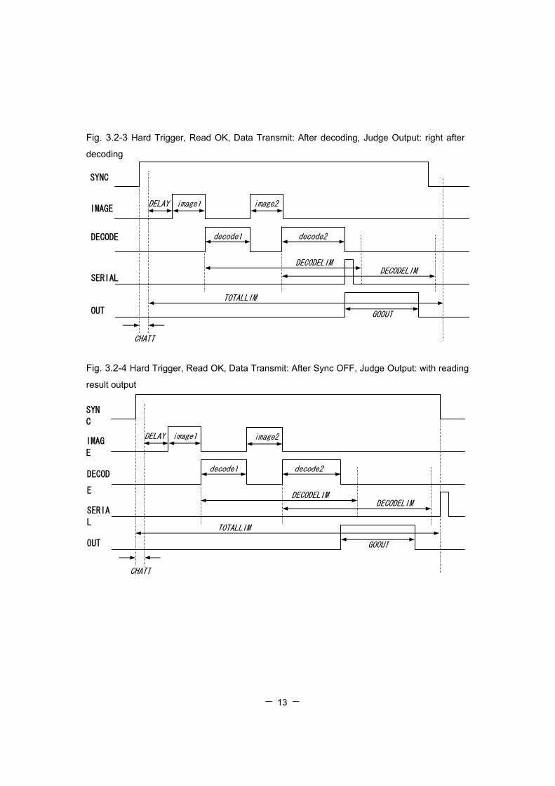
3.2 Read Time Out Mode After trigger input, the unit starts the timer for setting interval duration (setting command
TOTALLIM=). When the reading operation is failed, an error code transmits after the end of the
reading time set up by TOTALLIM.
SYNC
IMAGE
DECODE
SERIAL
OUT GOOUT
DECODELIMDECODELIM
decode1 decode2
image1
TOTALLIM
image2
Fig. 3.2-1 Soft Trigger, Read OK, Data Transmit: After decoding, Judge Output: with reading result output
DELAY
SYNC
IMAGE
DECODE
SERIAL
OUT GOOUT
DECODELIM DECODELIM
decode1 decode2
image1 image2
TOTALLIM
Fig. 3.2-2 Soft Trigger, Read OK, Data Transmit: After Sync OFF, Judge Output: with
reading result output
- - 13
Fig. 3.2-3 Hard Trigger, Read OK, Data Transmit: After decoding, Judge Output: right after
decoding
DELAY
SYNC
IMAGE
DECODE
SERIAL
OUT GOOUT
CHATT
DECODELIM DECODELIM
decode1 decode2
image1 image2
TOTALLIM
DELAY
SYN
C
IMAG
E
DECOD
E
SERIA
L
OUT GOOUT
CHATT
DECODELIM DECODELIM
decode1 decode2
image1
TOTALLIM
Fig. 3.2-4 Hard Trigger, Read OK, Data Transmit: After Sync OFF, Judge Output: with reading
result output
image2

- - 14
Fig. 3.2-5 Soft Trigger, Read NG, Data Transmit: After Sync OFF or right after decoding, Judge
Output: with reading result output
Successful decoding must be ended within the specified TOTALLIM time.
DELAY
SYNC
IMAGE
DECODE
SERIAL
OUT NGOUT
DECODELIMDECODELIM
decode1 decode2
image1 image2
TOTALLIM
- - 15
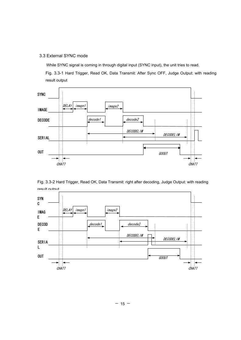
3.3 External SYNC mode
While SYNC signal is coming in through digital input (SYNC input), the unit tries to read.
Fig. 3.3-1 Hard Trigger, Read OK, Data Transmit: After Sync OFF, Judge Output: with reading
result output
decode1
DELAY
SYN
C
IMAG
E
DECOD
E
SERIA
L
OUT GOOUT
CHATT
DECODELIM DECODELIM
decode2
image1 image2
Fig. 3.3-2 Hard Trigger, Read OK, Data Transmit: right after decoding, Judge Output: with reading
result output
CHATT
decode2 decode1
DELAY
SYNC
IMAGE
DECODE
SERIAL
OUT GOOUT
CHATT
DECODELIM DECODELIM
image1 image2
CHATT

- - 16
DELAY
SYNC
IMAGE
DECODE
SERIAL
OUT NGOUT
CHATT
DECODELIM DECODELIM
decode1 decode2
image1 image2
CHATT
Fig. 3.3-3 Hard Trigger, Read NG, Data Transmit: After Sync OFF or right after decoding, Judge
Output: with reading result output

- - 17
3.4 Continuous Reading Mode
Sending the continuous read command “continue“ to the unit starts the next operation. Send the
stop command “stop” to end operation. Use this mode for the camera adjustment.
3.5 Test Mode
To enter this mode, (TEST=1) command should be transmitted to the unit using serial interface
and reading is started, the unit will start reading the symbol for 10 times (default). After each
reading process, the user will notice that an asterisk (*) will appear on he screen
[Example Output TEST Mode 1 Reading]
**** TEST MODE ****
1 2 3 4 5 6 7 8 9 10
*************************
NG 1:OK 99/SYNC 100
NG 1.00%:OK 99.00%
[Display ]
NGaaaaa:OKbbbbb/SYNCccccc[CR]
NGddd.dd%:Okeee.ee%[CR]
Explanations;
aaaaa : Reading NG Count
(0 - 65535, It keeps number at 65535 when counts more than 65536)
bbbbb : Reading OK Count
(0 - 65535, It keeps number at 65535 when counts more than 65536)
ccccc : SYNC Input Not display more than 65535)
ddd.dd: Reading NG Rate
(0.00-100.00, It displays to the second place below a decimal point)
eee.ee: Reading OK Rate
(0.00-100.00, It displays to the second place below a decimal point)

- - 18
3.6 Swing Mode
The unit will enter this mode by sending “AGC=S” command to the unit. In this mode, image
capture and decoding are performed based on a configuration that is previously stored for AGC
and shutter speed for respective image capture.
In this mode, Up to eight shutter speed, AGC values and image preprocessing can be stored.
Command Contents
SWAn=a
The AGC value of the n-th image is setup as a. a=0-255 *Value a can be set number 0 to 255. *When setup as SWAn=0, after the n-th setup is ignore, then setup of Image imag1 to imagn-1 are execution. Refer below table.
SWSn=a
The shutter speed of the n-th image is set as a. *Value a can be set number 0 to 7. Setting contents of shutter speed by value a, it will be same setting contents as SHUTT command (fixed mode).
SWLn=a The illumination control of the n-th image is set as a. **Value a can be set the same number as the serial command “LIGHT=a”.
e.g. Pre-registered setup of Swing values
Swing pair number Example Values Set
1 SWA1=185 (Gain:0-255) SWS1=3 (Shutt:0-7) 2 SWA2=210 (Gain:0-255) SWS2=3 (Shutt:0-7) 3 SWA3=0 (Gain:0-255) SWS3=3 (Shutt:0-7) 4 SWA4=255 (Gain:0-255) SWS4=0 (Shutt:0-7) 5 SWA5=255 (Gain:0-255) SWS5=0 (Shutt:0-7) 6 SWA4=255 (Gain:0-255) SWS4=0 (Shutt:0-7) 7 SWA4=255 (Gain:0-255) SWS4=0 (Shutt:0-7) 8 SWA4=255 (Gain:0-255) SWS4=0 (Shutt:0-7)
In the above-shown setup, Swing pair numbers 1 and 2 are enabled with Gain and Shutter
settings. Set number 3 is set to zero, meaning that Swing pairs 3 through 8 are disabled.
- - 19
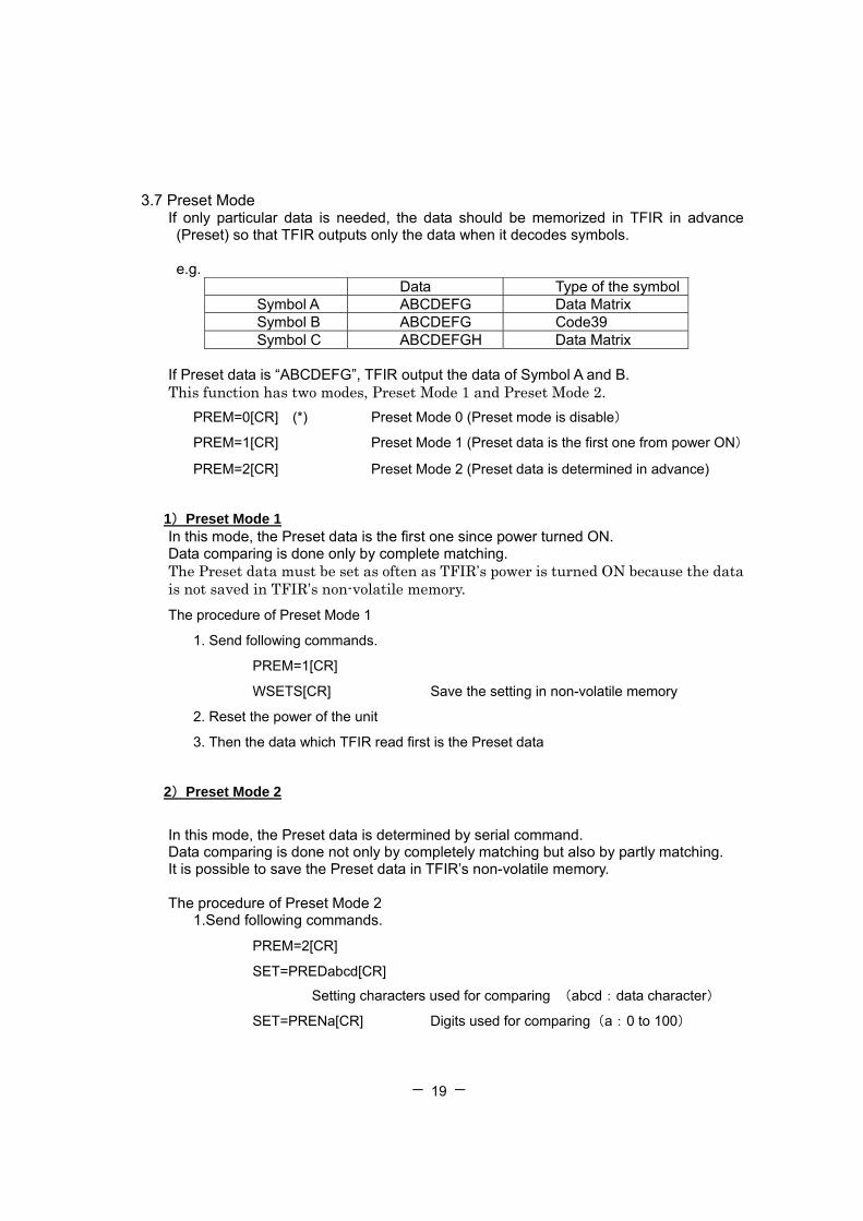
3.7 Preset Mode If only particular data is needed, the data should be memorized in TFIR in advance (Preset) so that TFIR outputs only the data when it decodes symbols.
e.g.
Data Type of the symbol Symbol A ABCDEFG Data Matrix Symbol B ABCDEFG Code39 Symbol C ABCDEFGH Data Matrix
If Preset data is “ABCDEFG”, TFIR output the data of Symbol A and B. This function has two modes, Preset Mode 1 and Preset Mode 2. PREM=0[CR] (*) Preset Mode 0 (Preset mode is disable)
PREM=1[CR] Preset Mode 1 (Preset data is the first one from power ON)
PREM=2[CR] Preset Mode 2 (Preset data is determined in advance)
1)Preset Mode 1 In this mode, the Preset data is the first one since power turned ON. Data comparing is done only by complete matching. The Preset data must be set as often as TFIR’s power is turned ON because the data is not saved in TFIR’s non-volatile memory. The procedure of Preset Mode 1
1. Send following commands.
PREM=1[CR]
WSETS[CR] Save the setting in non-volatile memory
2. Reset the power of the unit
3. Then the data which TFIR read first is the Preset data
2)Preset Mode 2
In this mode, the Preset data is determined by serial command. Data comparing is done not only by completely matching but also by partly matching. It is possible to save the Preset data in TFIR’s non-volatile memory. The procedure of Preset Mode 2 1.Send following commands.
PREM=2[CR]
SET=PREDabcd[CR]
Setting characters used for comparing (abcd:data character)
SET=PRENa[CR] Digits used for comparing(a:0 to 100)
- - 20
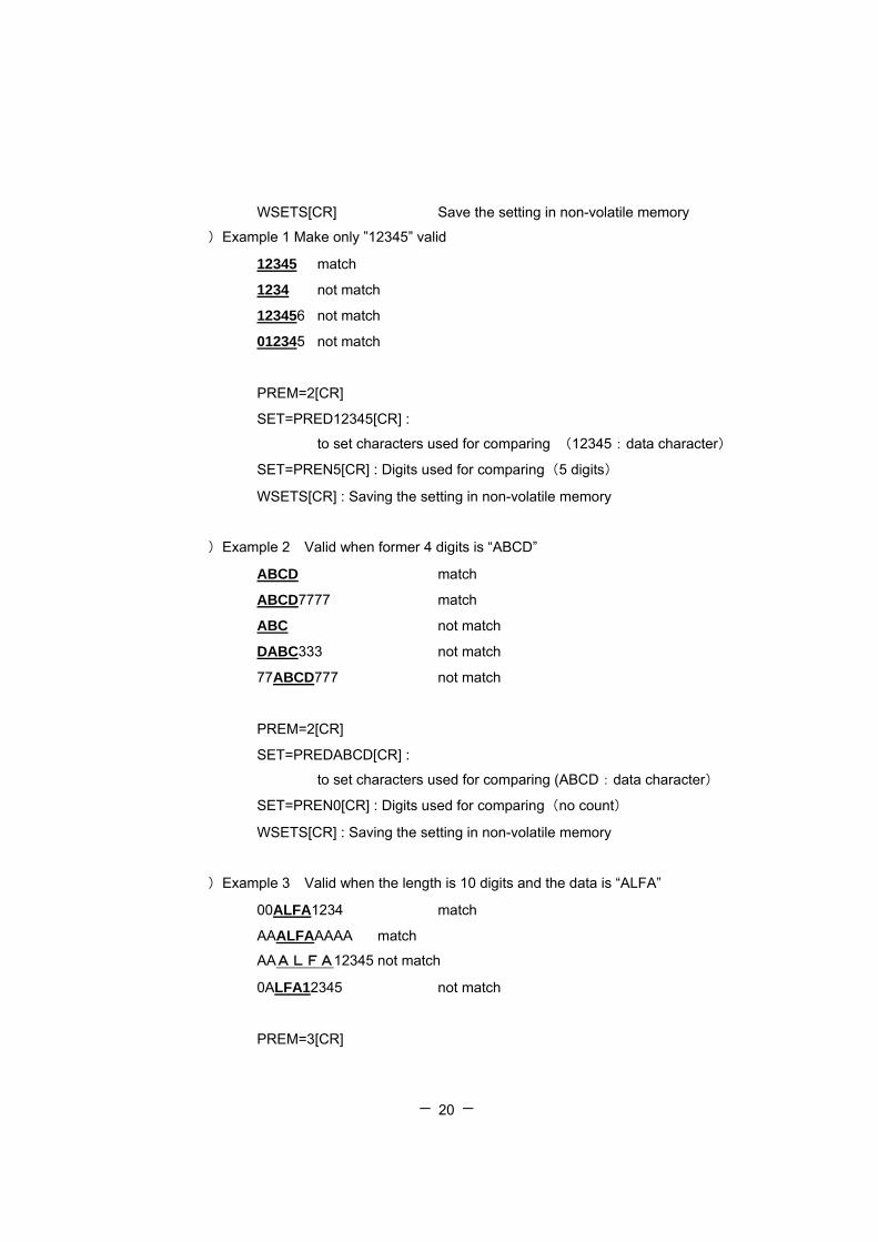
WSETS[CR] Save the setting in non-volatile memory
)Example 1 Make only ”12345” valid
12345 match
1234 not match
123456 not match
012345 not match
PREM=2[CR]
SET=PRED12345[CR] :
to set characters used for comparing (12345:data character)
SET=PREN5[CR] : Digits used for comparing(5 digits)
WSETS[CR] : Saving the setting in non-volatile memory
)Example 2 Valid when former 4 digits is “ABCD”
ABCD match
ABCD7777 match
ABC not match
DABC333 not match
77ABCD777 not match
PREM=2[CR]
SET=PREDABCD[CR] :
to set characters used for comparing (ABCD:data character)
SET=PREN0[CR] : Digits used for comparing(no count)
WSETS[CR] : Saving the setting in non-volatile memory
)Example 3 Valid when the length is 10 digits and the data is “ALFA”
00ALFA1234 match
AAALFAAAAA match
AAALFA12345 not match
0ALFA12345 not match
PREM=3[CR]

- - 21
SET=PRED??ALFA????[CR]:
to set characters used for comparing (??ALFA????:data character)
SET=PREN10[CR] : Digits used for comparing(10 digits)
WSETS[CR] : Saving the setting in non-volatile memory
3)Output the Preset status
?pre[CR] Output the Preset status
(example of output)
PREM=0 (0:non 1:power on 2:saved)
PRESET LENGTH:41
DATA(HEX):
31 32 33 3F 3F 3F 3F 3F 3F 3F
3F 41 42 43 43 44 45 03 04 05
3F 3F 3F 3F 3F 3F 3F 3F 3F 3F
3F 3F 3F 3F 3F 3F 3F 3F 39 31
30
DATA(ASCII):
123????????ABCCDE***??????????????????910
(Format of output)
PREM=a (0:non 1:power on 2:saved)[CR]
PRESET LENGTH:b[CR]
DATA(HEX):[CR]
XX XX XX XX XX XX XX XX XX XX[CR]
XX XX XX XX XX XX XX XX XX XX[CR]
XX XX XX XX [CR]
DATA(ASCII):[CR]
xxxxxxxxxxxxxxxxxxxxxxxx
a :Preset Mode
b :The digit of Preset data
XX XX … :Preset data character (in hex)
xxxxxx… :Preset data character (in ASCII/JIS)
If the preset data include control code, it is transferred to “*”.
- - 22
3.8 Description of Diagnosis mode
1) Confirmation for Output of Reading statistics and Decoding Time
[Reading OK and NG Count Number Output Example]
*** TOTAL *** NG 1:OK 99/SYNC 100 NG 1.00%:OK 99.00%
[Reading Ok and Ng Decoding Time Output Example]
*** DECODE TIME *** OK: min(0118ms),max(0124ms),ave(0120ms) NG: min(0148ms),max(0148ms),ave(0148ms) NG 1:OK 99/SYNC 100
Note
When setup mode is executed, Count Number and Total Decoding Time will be cleared.
2) Output decode time
The actual time consumed during symbol decoding, setting up disable or enable to the output
data in the serial interface output.
Usually, during this mode (SYNCMODE=0), if the timeout time set up value passes when a label
cannot be recognized in a image, decoding operation will be stopped and it will become reading
NG process.
When in Timeout Mode (SYNCMODE=1), if a label cannot be recognized in an image, if it
remains with reading timeout and time excels rather than decoding timeout, the next image
capture (decoding) will be started, and if shorter than decoding timeout, it will become reading
NG.
When External Synchronous Continuation Reading Mode is used(SYNCMODE=2), when a label
cannot be recognized in a picture, the state of a synchronized signal is investigated, if it is in ON
state, the next image (decoding) will be started, and if it is in an OFF state, it will become reading
NG treatment.

- - 23
3) Output of total decoding time
This unit can output, in addition to the decoded data, the total reading time (time from SYNC ON
to an OK data output) as well as the number of pictures acquired from SYNC ON to the
successful decoding. (This can not be done when reading result is NG.)
Display Format: aa,bbbbbms
xxxxxxx Captured Image number
xxxxxxxxx Total Reading Time Unit [ms]
4) Symbol Code character System
Symbol System
Code Character
Symbol System
Code Character
Code39 ]A0 UPC/EAN/JAN No Code Code128 ]C0 Data Matrix ]d1 EAN-128 ]C1 Maxi Code ]U1
CODABAR ]F0 PDF417 ]L0 ITF ]I0 QR Code ]Q1
- - 24
5) Contrast Information
This is used to enable or disable adding image contrast information.
It output image contrast information after last captured and decoded image.
i) In case of OK reading
The contrast information in symbol recognition area is transmitted.
Finding rectangular coordinate from the minimum and maximum of the square coordinates of a
symbol is calculated from the area of contrast information.
When two or more symbols exist, the contrast information on the previously recognized is
outputted.
ii) In case of NG reading
The contrast information in setup area is transmitted. (Default setup: All image area)
Format:: aaa, bbb, ccc
aaa: Contrast Maximum value (0 - 255 )
bbb: Contrast Minimum value (0 - 255 )
ccc: 100 x (Maximum value - Minimum value) / 255 (0 - 100)
Data Length:13 byte
6) Quality Information
This is used to enable or disable adding quality information.
For 2-dimentional symbol, it will only output percentage that error correction was NOT performed.
In case of using good quality of symbol, it will output 100. This can not be used when reading NG.
Format:: QT: ddd
ddd: Contrast Maximum value (0 - 255 )
Data Length:8 byte
- - 25
7) Output the coordinate of the symbol
The setting to output the information of the symbol’s position in the field of view is available.
There are three types of output, coordinate of the center and/or the coordinate of four
apexes.
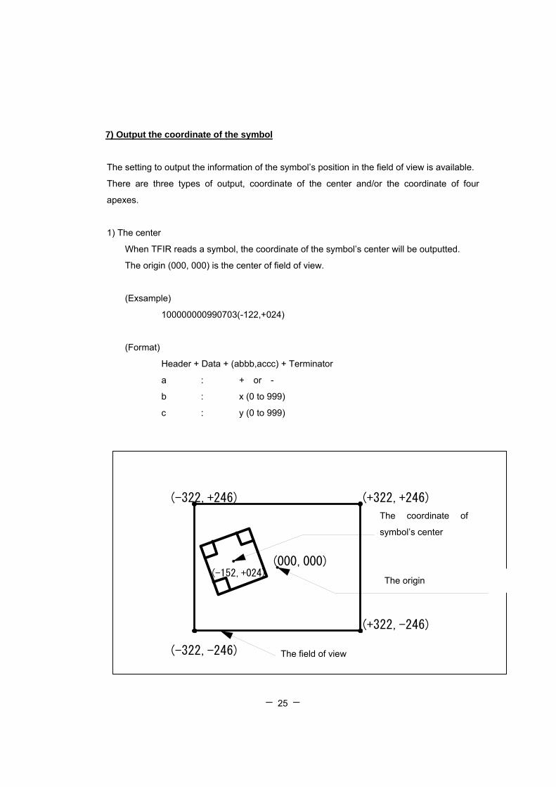
1) The center
When TFIR reads a symbol, the coordinate of the symbol’s center will be outputted.
The origin (000, 000) is the center of field of view.
(Exsample)
100000000990703(-122,+024)
(Format)
Header + Data + (abbb,accc) + Terminator
a : + or -
b : x (0 to 999)
c : y (0 to 999)
重心座標
(-322,+246) (+322,+246)
(+322,-246)
(-322,-246) 画面
(000,000)(-152,+024)
重心座標
重心座標 原点
重心座標
(-322,+246) (+322,+246)
(+322,-246)
(-322,-246) 画面
(000,000)(-152,+024)
重心座標
重心座標 原点
The coordinate of
symbol’s center
The origin
The field of view
- - 26
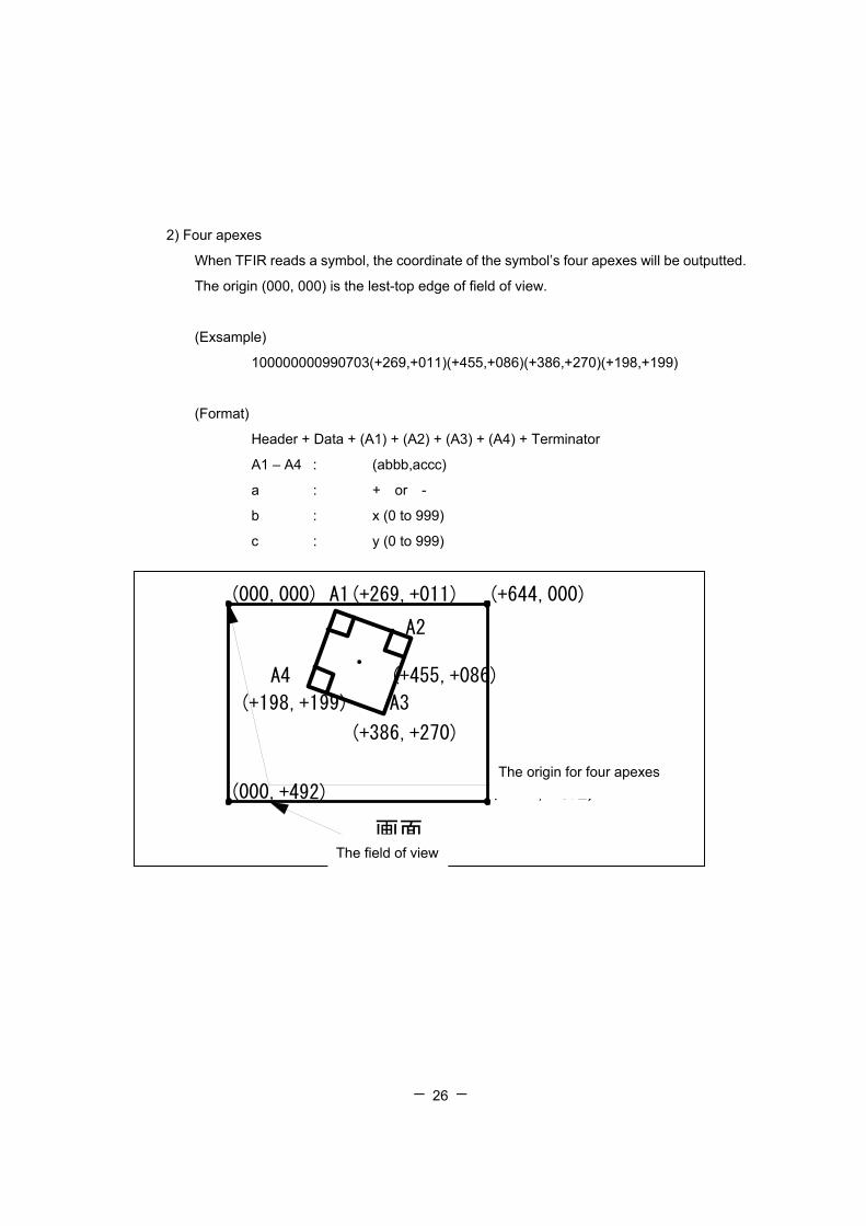
2) Four apexes
When TFIR reads a symbol, the coordinate of the symbol’s four apexes will be outputted.
The origin (000, 000) is the lest-top edge of field of view.
(Exsample)
100000000990703(+269,+011)(+455,+086)(+386,+270)(+198,+199)
(Format)
Header + Data + (A1) + (A2) + (A3) + (A4) + Terminator
A1 – A4 : (abbb,accc)
a : + or -
b : x (0 to 999)
c : y (0 to 999)
(+644,+492)(000,+492)
画面
(+644,000)(000,000) A1(+269,+011)
(+198,+199)
A4
(+386,+270)
(+455,+086)
A3
A2
4角座標 原点
The field of view
The origin for four apexes
- - 27
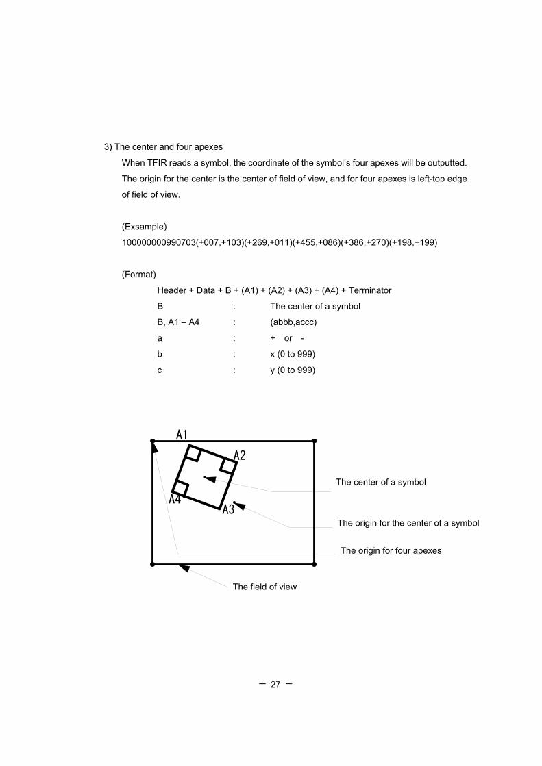
3) The center and four apexes
When TFIR reads a symbol, the coordinate of the symbol’s four apexes will be outputted.
The origin for the center is the center of field of view, and for four apexes is left-top edge
of field of view.
(Exsample)
100000000990703(+007,+103)(+269,+011)(+455,+086)(+386,+270)(+198,+199)
(Format)
Header + Data + B + (A1) + (A2) + (A3) + (A4) + Terminator
B : The center of a symbol
B, A1 – A4 : (abbb,accc)
a : + or -
b : x (0 to 999)
c : y (0 to 999)
画面
重心・4角座標
A2
A3A4
A1
重心座標
重心座標 原点
4角座標 原点
The field of view
The center of a symbol
The origin for the center of a symbol
The origin for four apexes

- - 28
3.9 Auto detection mode
3.9.1 Overview
By using this mode, TFIR-31DM can read and decode symbols automatically.
TFIR-31DM detects changes of image in its field of view, like change of environmental
brightness, motion of objects. When there is such a change, TFIR-31DM starts to
capture an image and tries to decode.
This function is designed to read documents with printed barcodes. For example, it is
suitable for use on the counter at post office.
CAUTION
Auto Detection mode may not work well under too high, too low or unstable brightness.
With Auto Detection mode, trigging by serial command and digital signal input do not
work.
Plus, neither does capturing an image, receiving a Hex program, executing a Macro
program, continous reading and test mode. Please turn Auto Detection mode OFF if
those function are needed to be used.
Field of view Object with barcode
TFIR-31DM
- - 29
3.9.2 How to use
To put TFIR-31DM in the auto detection mode, please follow one of the following
methods:
- Send the serial command "SYNCMODE=3<CR>" to the scanner.
- Read the corresponding barcode from the configuration barcode set.
To exit the auto detection mode, please follow one of the following methods:
- Send the serial command "SYNCMODE=0 (or 1 or 2)<CR>" to the scanner.
- Read the corresponding barcode from the configuration barcode set.
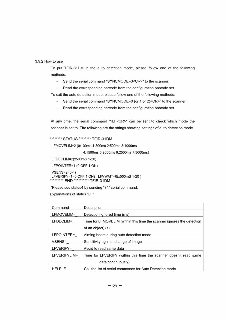
At any time, the serial command "?LF<CR>" can be sent to check which mode the
scanner is set to. The following are the strings showing settings of auto detection mode.
******** STATUS ******** TFIR-31DM
LFMOVELIM=2 (0:100ms 1:300ms 2:500ms 3:1000ms
4:1500ms 5:2000ms 6:2500ms 7:3000ms)
LFDECLIM=2(x500mS 1-20)
LFPOINTER=1 (0:OFF 1:ON)
VSENS=2 (0-4) LFVERIFY=1 (0:OFF 1:ON) LFVWAIT=6(x500mS 1-20 )
********* END ********** TFIR-31DM
*Please see status4 by sending “?4” serial command.
Explanations of status “LF”
Command Description
LFMOVELIM=_ Detection ignored time (ms)
LFDECLIM=_ Time for LFMOVELIM (within this time the scanner ignores the detection
of an object) (s)
LFPOINTER=_ Aiming beam during auto detection mode
VSENS=_ Sensitivity against change of image
LFVERIFY=_ Avoid to read same data
LFVERIFYLIM=_ Time for LFVERIFY (within this time the scanner doesn’t read same
data continuously)
HELPLF Call the list of serial commands for Auto Detection mode

- - 30
3.9.3 Serial Command
i) Enable/Disable Auto-detection mode
Enable : SYNCMODE=3
Disable : SYNCMODE=0 or 1 or 2
ii) Timeout: Label disappear (LFMOVELIM)
After detecting an object, the unit starts waiting for the object go out form the field of
view.
The limit time for the waiting can be configured. If the limit time is short, please remove
the object immediately. If large objects are supposed to be in the FOV, please set the
time long.
iii) Timeout: Decoding (LFDECLIM)
The unit gives up decoding after trying to decode within specified time. The limit time
can be configured. For barcodes which have large amount of data or difficulty to read, please
set the limit long.
iv) Aimer setting during Auto-detection mode (LFPOINTER)
Set the behavior of aimer while the unit is in Auto-detection mode and waiting an object
coming into the FOV.
v) Sensitivity against brightness (VSENS)
Configure the sensitivity against brightness. If the unit tends to miss the object coming
in, please set sensitivity higher.

- - 31
vi) Prohibit to read the same data (LFVERIFY)
If this parameter is enabled, the unit does not read barcodes which have identical data
within the specified limit time.
vii) Limit time for LFVERIFY (LFVWAIT)
Limit time for LFVERIFY.
viii) The list of serial commands for Auto-detection (HELPLF)
Display the list of serial commands for Auto-detection.
ix) The list of status regarding to Auto-detection (?LF)
Display the list of status regarding to Auto-detection like the following.
(Example) ******** STATUS ******** TFIR-XXXX
LFMOVELIM=2 (0:100ms 1:300ms 2:500ms 3:1000ms
4:1500ms 5:2000ms 6:2500ms 7:3000ms)
LFDECLIM=2(x500mS 1-20 )
LFPOINTER=1 (0:OFF 1:ON)
VSENS=2 (0-4)
LFVERIFY=1 (0:OFF 1:ON) LFVWAIT=6(x500mS 1-40 ) ********* END ********** TFIR-XXXX

- - 32
3.9.4 Flow chart
Standby
“Label in”Detected?
Decoded?
Aiming beam: Blinking
Verify
Compare decoded data with last decode data.
Try to decode
No: Timeout
Make an object with barcodes gone into TFIR-31’s field of
view
Yes
Yes
Different data Same data
No
Yes
Within detection
ignored limit?
No
No: Timeout
Out put the decoded data
YesGO/NGGO?
Monitor LED: Green
Yes
Yes
GO/NGNG?
Label out Detected?
No
Within decoding time
limit?
Monitor LED: Orange
Monitor LED: Red
Yes
- - 33
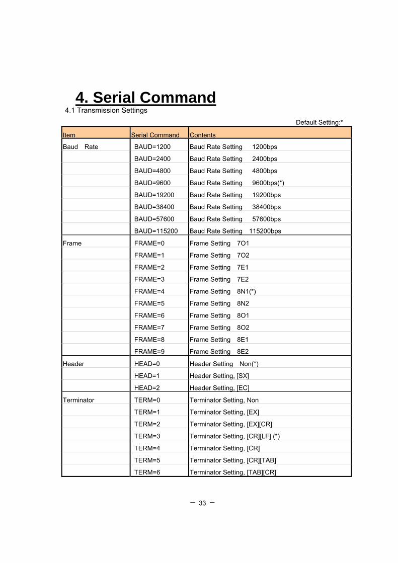
4. Serial Command 4.1 Transmission Settings
Default Setting:*
Item Serial Command Contents
Baud Rate BAUD=1200 Baud Rate Setting 1200bps
BAUD=2400 Baud Rate Setting 2400bps
BAUD=4800 Baud Rate Setting 4800bps
BAUD=9600 Baud Rate Setting 9600bps(*)
BAUD=19200 Baud Rate Setting 19200bps
BAUD=38400 Baud Rate Setting 38400bps
BAUD=57600 Baud Rate Setting 57600bps
BAUD=115200 Baud Rate Setting 115200bps
Frame FRAME=0 Frame Setting 7O1
FRAME=1 Frame Setting 7O2
FRAME=2 Frame Setting 7E1
FRAME=3 Frame Setting 7E2
FRAME=4 Frame Setting 8N1(*)
FRAME=5 Frame Setting 8N2
FRAME=6 Frame Setting 8O1
FRAME=7 Frame Setting 8O2
FRAME=8 Frame Setting 8E1
FRAME=9 Frame Setting 8E2
Header HEAD=0 Header Setting Non(*)
HEAD=1 Header Setting, [SX]
HEAD=2 Header Setting, [EC]
Terminator TERM=0 Terminator Setting, Non
TERM=1 Terminator Setting, [EX]
TERM=2 Terminator Setting, [EX][CR]
TERM=3 Terminator Setting, [CR][LF] (*)
TERM=4 Terminator Setting, [CR]
TERM=5 Terminator Setting, [CR][TAB]
TERM=6 Terminator Setting, [TAB][CR]

- - 34
Item Serial Command Contents
Separator SEPA=0 Separator Setting, Non
SEPA=1 Separator Setting, &
SEPA=2 Separator Setting, ,
SEPA=3 Separator Setting, [FS] ( 1C hex ) (*)
SEPA=4 Separator Setting, [GS] ( 1D hex )
SEPA=5 Separator Setting, [SP] ( 20 hex ) Prefix PREFIX=a Set a character for prefix =a,¥bb a=0; Disable (*)、a=1; Enable =a,c bb; Prefix char (HEX)、cc; Character =a,[dd] dd; Char in ASCII(¥00-¥1F)
bb,c,dd If skipped, the character set before is not changed.
Suffix SUFFIX=a Set a character for suffix =a,¥bb a=0; Disable (*)、a=1; Enable =a,c bb; Prefix char (HEX)、cc; Character =a,[dd] dd; Char in ASCII(¥00-¥1F)
bb,c,dd If skipped, the character set before is not changed.
RS/CS Control RSCS=0 Not use RS-CS control signal
RSCS=1 Use RS-CS control signal(*)
Control Character LABELTX=0 Output control code: Pass through control characters(*)
LABELTX=1 Output control code: Convert control characters to hex
digits as an ASCII
Timeout Duration TXWAIT=a Decoding Data Timeout duration a=1000-2500; unit[msec],10[msec]per

- - 35
4.2 Reading Symbols Item Command Contents Common Setting
SET=#M1 Disable reading of all 1-D and 2-D Symbol System
SET=#M0 Enable reading of all 1-D and 2-D Symbol System SYMHEAD=#a Set symbol header for all symbol types. =#a,¥bb a=0; Disable (*), a=1; Enable =#a,c bb; Char for Identifier (HEX), c; Character =#a,[dd] dd; Char in ASCII(¥00-¥1F)
bb,c,dd If skipped, the character set before is not changed.
SYMFOOT=#a Set symbol footer for all symbol types. =#a,¥bb a=0; Disable (*), a=1; Enable =#a,c bb; Char for Identifier (HEX), c; Character =#a,[dd] dd; Char in ASCII(¥00-¥1F)
bb,c,dd If skipped, the character set before is not changed.
Code39 SET=AM0 Disable reading of Code39(*) SET=AM1 Read Code39, Disable C/D Check SET=AM2 Read Code39, Enable C/D Check, C/D Transmit SET=AM3 Read Code39, Enable C/D Check, No C/D Transmit SET=AM4 Read Code39, Disable C/D Check , Enable FULL ASCII
SET=AM5 Read Code39, Enable C/D Check, C/D Transmit, Enable FULL
ASCII
SET=AM6 Read Code39, Enable C/D Check, No C/D Transmit, Enable FULL
ASCII C39SS=0 Disable Transmit Start/Stop Code of Code39(*) C39SS=1 Enable Transmit Start/Stop Code of Code39
DIGIT=Ab,c Set reading range of Code39 Min. digits (b digits), Max. digits(c
digits) EDIT=Ab,c Code39 with edit Transmit specific “b” digits through “c” digits

- - 36
Item Command Contents
Code128 SET=CM0 Disable reading of Code128(*) SET=CM1 Enable reading of Code128
DIGIT=Cb,c Set Code128 reading range from Min. digits (b digits) to
Max. digits(c digits) EDIT=Cb,c Edit Transmit specific “b” digits through “c” digits of Code128 EAN-128 SET=eM0 Disable reading of EAN128(*) SET=eM1 Enable reading of EAN128 E128GS=0 Disable Control Character [GS] Transmitting is set for EAN-128 E128GS=1 Enable Control Character [GS] Transmitting is set for EAN-128
DIGIT=eb,c Set EAN128 reading range from Min. digits (b digits) to
Max. digits(c digits) EDIT=eb,c Edit Transmit specific “b” digits through “c” digits of EAN128 ITF SET=IM0 Disable reading of ITF(*) SET=IM1 Enable reading of ITF, Disable C/D Check SET=IM2 Enable reading of ITF, Enable C/D Check, C/D Transmit SET=IM3 Enable reading of ITF, Enable C/D Check, No C/D Transmit DIGIT=Ib,c Set reading range of ITF Min. digits (b digits), Max. digits(c digits) EDIT=Ib,c ITF with edit Transmit specific “b” digits through “c” digits Code93 SET=GM0 Disable reading of Code93 (*) SET=GM1 Enable reading of Code93 DIGIT=Gb,c Set reading range of Code93 Min. digits (b digits), Max. digits (c digits) EDIT=Gb,c Code93 with edit Transmit specific “b” digits through “c” digits
SYMHEAD=Ga Set a header of Code93 optionally
=Ga,¥bb a=0; disable (*)、a=1; enable =Ga,c bb; the character used for comparing (Hex)、c; character =Ga,[dd] dd; the character in ASCIIcode(¥00-¥1F) bb,c,dd; when it is skipped, the latest character is remained
SYMFOOT=Ga Set a header of Code93 optionally
=Ga,¥bb a=0; disable (*)、a=1; enable =Ga,c bb; the character used for comparing (Hex)、c; character =Ga,[dd] dd; the character in ASCIIcode(¥00-¥1F) bb,c,dd; when it is skipped, the latest character is remained

- - 37
Item Command Contents UPC/EAN/JAN SET=EM0 Disable reading UPC/EAN/JAN(*) SET=EM1 Enable reading UPC/EAN/JAN
JE13SUM=0 Enable Check Sum Transmitting is set for Standard JAN/EAN
(Include Add-on) (*)
JE13SUM=1 Disable Check Sum Transmitting is set for Standard JAN/EAN
(Include Add-on)
JE8SUM=0 Enable Check Sum Transmitting is set for Shortened
JAN/EAN(Include Add-on) (*)
JE8SUM=1 Disable Check Sum Transmitting is set for Shortened
JAN/EAN(Include Add-on) UASUM=0 Enable Check Sum Transmitting is set for UPC-A(*) UASUM=1 Disable Check Sum Transmitting is set for UPC-A UESUM=0 Enable Check Sum Transmitting is set for UPC-E (*) UESUM=1 Disable Check Sum Transmitting is set for UPC-E UPCANS=0 Enable Number System Transmitting is set for UPC-A(*) UPCANS=1 Disable Number System Transmitting is set for UPC-A UPCENS=0 Enable Number System Transmitting is set for UPC-E(*) UPCENS=1 Disable Number System Transmitting is set for UPC—E UPCE=0 Convert UPC-E codes to UPC-A format (*) UPCE=1 Leave UPC-E formats unchanged UPCTX=0 Leaves 12 digit codes unchanged(*) UPCTX=1 Adds a leading zero to 12 digit UPC codes UPC-A
DIGIT=Eb,c Set reading range of UPC/JAN/EAN Min. digits (b digits),
Max. digits(c digits)
EDIT=Eb,c UPC/JAN/EAN with edit Transmit specific “b” digits through “c”
digits
- - 38
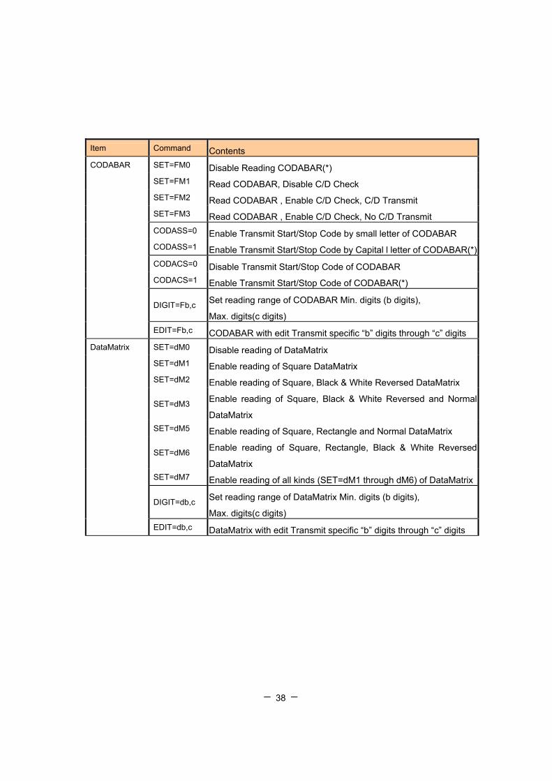
Item Command Contents CODABAR SET=FM0 Disable Reading CODABAR(*) SET=FM1 Read CODABAR, Disable C/D Check SET=FM2 Read CODABAR , Enable C/D Check, C/D Transmit SET=FM3 Read CODABAR , Enable C/D Check, No C/D Transmit CODASS=0 Enable Transmit Start/Stop Code by small letter of CODABAR CODASS=1 Enable Transmit Start/Stop Code by Capital l letter of CODABAR(*) CODACS=0 Disable Transmit Start/Stop Code of CODABAR CODACS=1 Enable Transmit Start/Stop Code of CODABAR(*)
DIGIT=Fb,c Set reading range of CODABAR Min. digits (b digits),
Max. digits(c digits) EDIT=Fb,c CODABAR with edit Transmit specific “b” digits through “c” digits DataMatrix SET=dM0 Disable reading of DataMatrix SET=dM1 Enable reading of Square DataMatrix SET=dM2 Enable reading of Square, Black & White Reversed DataMatrix
SET=dM3 Enable reading of Square, Black & White Reversed and Normal
DataMatrix SET=dM5 Enable reading of Square, Rectangle and Normal DataMatrix
SET=dM6 Enable reading of Square, Rectangle, Black & White Reversed
DataMatrix SET=dM7 Enable reading of all kinds (SET=dM1 through dM6) of DataMatrix
DIGIT=db,c Set reading range of DataMatrix Min. digits (b digits),
Max. digits(c digits) EDIT=db,c DataMatrix with edit Transmit specific “b” digits through “c” digits
- - 39
Item Command Contents
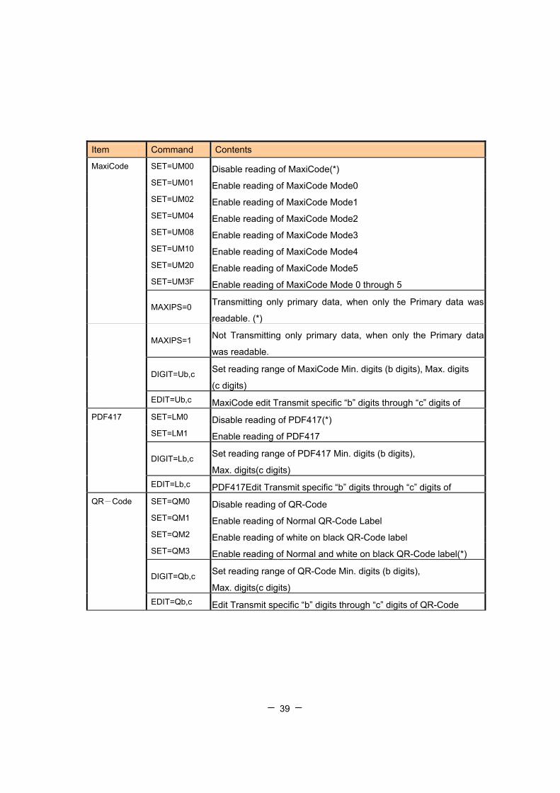
MaxiCode SET=UM00 Disable reading of MaxiCode(*) SET=UM01 Enable reading of MaxiCode Mode0 SET=UM02 Enable reading of MaxiCode Mode1 SET=UM04 Enable reading of MaxiCode Mode2 SET=UM08 Enable reading of MaxiCode Mode3 SET=UM10 Enable reading of MaxiCode Mode4 SET=UM20 Enable reading of MaxiCode Mode5 SET=UM3F Enable reading of MaxiCode Mode 0 through 5
MAXIPS=0 Transmitting only primary data, when only the Primary data was
readable. (*)
MAXIPS=1 Not Transmitting only primary data, when only the Primary data
was readable.
DIGIT=Ub,c Set reading range of MaxiCode Min. digits (b digits), Max. digits
(c digits) EDIT=Ub,c MaxiCode edit Transmit specific “b” digits through “c” digits of PDF417 SET=LM0 Disable reading of PDF417(*) SET=LM1 Enable reading of PDF417
DIGIT=Lb,c Set reading range of PDF417 Min. digits (b digits),
Max. digits(c digits) EDIT=Lb,c PDF417Edit Transmit specific “b” digits through “c” digits of QR-Code SET=QM0 Disable reading of QR-Code SET=QM1 Enable reading of Normal QR-Code Label SET=QM2 Enable reading of white on black QR-Code label SET=QM3 Enable reading of Normal and white on black QR-Code label(*)
DIGIT=Qb,c Set reading range of QR-Code Min. digits (b digits),
Max. digits(c digits) EDIT=Qb,c Edit Transmit specific “b” digits through “c” digits of QR-Code

- - 40
Item Command Contents
SET=eM00-RSS Disable reading of RSS(*) SET=eM01-RSS Enable reading of RSS Expanded SET=eM02-RSS Enable reading of RSS Expanded Stacked SET=eM04-RSS Enable reading of RSS Limited SET=eM08-RSS Enable reading of RSS-14 and RSS-14 Truncated
SET=eM10-RSS Enable reading of RSS-14 Stacked and RSS-14 Stacked
Omnidirectional SET=eM1F-RSS Enable reading of all types of RSS
DIGIT=eb,c-RSS Set reading range of RSS Min. digits (b digits), Max. digits(c
digits)
RSS
EDIT=eb,c-RSS Edit Transmit specific “b” digits through “c” digits of RSS Composite SET=eM00-CC Disable Composite code (*) SET=eM01-CC Enable UPC Composite SET=eM02-CC Enable RSS Composite SET=eM04-CC Enable Code128 Composite SET=eM07-CC Enable all composite SET=eM10-CC Output (only result of 1D code) (can’t be coexisted with eM20) SET=eM20-CC EAN 128 emulation mode (can’t be coexisted with eM10) DIGIT=eb,c-CC Minimum (b) & Maximum (c) number of digits for Composite EDIT=eb,c-CC Output from (b) to (c) digits of Composite data SYMHEAD Set symbol header for Composite code. =ea,¥bb-CC a=0; Disable (*), a=1; Enable =ea,c-CC bb; Char for Identifier (HEX), c; Character =ea,[dd]-CC dd; Char in ASCII(¥00-¥1F) bb,c,dd If skipped, the character set before is not changed. SYMFOOT Set symbol footer for Composite code =ea,¥bb-CC a=0; Disable (*), a=1; Enable =ea,c-CC bb; Char for Identifier (HEX), c; Character =ea,[dd]-CC dd; Char in ASCII(¥00-¥1F) bb,c,dd If skipped, the character set before is not changed.
- - 41
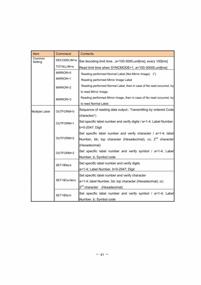
Item Command Contents Common Setting DECODELIM=a Set decoding limit time , a=100-3000,unit[ms], every 100[ms] TOTALLIM=a Read limit time when SYNCMODE=1, a=100-30000,unit[ms] MIRROR=0 Reading performed Normal Label (Not Mirror Image) (*) MIRROR=1 Reading performed Mirror Image Label
MIRROR=2 Reading performed Normal Label, then in case of No read occurred, try
to read Mirror Image.
MIRROR=3 Reading performed Mirror Image, then in case of No read occurred, try
to read Normal Label.
Multiple Label OUTFORM=0 Sequence of reading data output:: Transmitting by ordered Code
character(*)
OUTFORM=1 Set specific label number and verify digits / a=1-4; Label Number,
b=0-2047; Digit
OUTFORM=2 Set specific label number and verify character / a=1-4; label
Number, bb; top character (Hexadecimal), cc; 2nd character
(Hexadecimal)
OUTFORM=3 Set specific label number and verify symbol / a=1-4; Label
Number, b; Symbol code
SET=$Na-b Set specific label number and verify digits
a=1-4; Label Number, b=0-2047; Digit
SET=$Ca-bbcc Set specific label number and verify character
a=1-4; label Number, bb; top character (Hexadecimal), cc;
2nd character (Hexadecimal)
SET=$Sa-b Set specific label number and verify symbol / a=1-4; Label
Number, b; Symbol code
- - 42
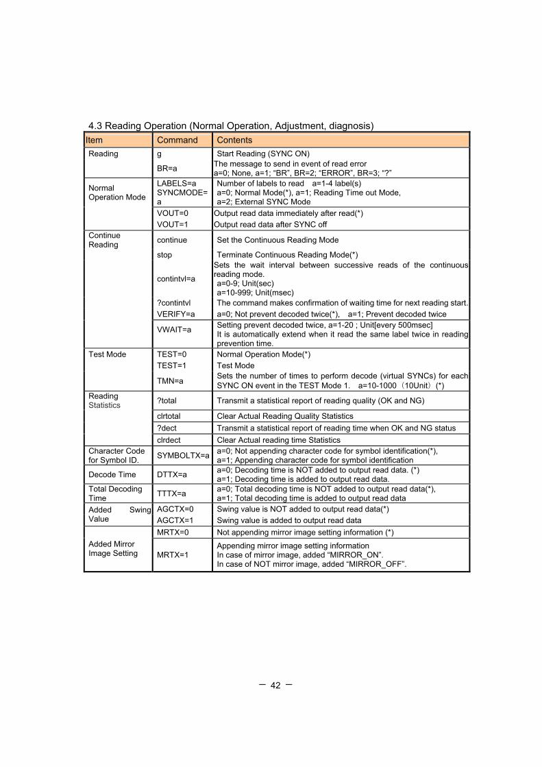
4.3 Reading Operation (Normal Operation, Adjustment, diagnosis) Item Command Contents Reading g Start Reading (SYNC ON)
BR=a The message to send in event of read error a=0; None, a=1; “BR”, BR=2; “ERROR”, BR=3; “?”
Normal Operation Mode
LABELS=a SYNCMODE=a
Number of labels to read a=1-4 label(s) a=0; Normal Mode(*), a=1; Reading Time out Mode, a=2; External SYNC Mode
VOUT=0 Output read data immediately after read(*) VOUT=1 Output read data after SYNC off Continue Reading continue Set the Continuous Reading Mode
stop Terminate Continuous Reading Mode(*)
contintvl=a
Sets the wait interval between successive reads of the continuous reading mode. a=0-9; Unit(sec) a=10-999; Unit(msec)
?contintvl The command makes confirmation of waiting time for next reading start. VERIFY=a a=0; Not prevent decoded twice(*), a=1; Prevent decoded twice
VWAIT=a
Setting prevent decoded twice, a=1-20 ; Unit[every 500msec] It is automatically extend when it read the same label twice in reading prevention time.
Test Mode TEST=0 Normal Operation Mode(*) TEST=1 Test Mode
TMN=a Sets the number of times to perform decode (virtual SYNCs) for each SYNC ON event in the TEST Mode 1. a=10-1000(10Unit)(*)
Reading Statistics ?total Transmit a statistical report of reading quality (OK and NG)
clrtotal Clear Actual Reading Quality Statistics ?dect Transmit a statistical report of reading time when OK and NG status clrdect Clear Actual reading time Statistics Character Code for Symbol ID. SYMBOLTX=a a=0; Not appending character code for symbol identification(*),
a=1; Appending character code for symbol identification
Decode Time DTTX=a a=0; Decoding time is NOT added to output read data. (*) a=1; Decoding time is added to output read data.
Total Decoding Time TTTX=a a=0; Total decoding time is NOT added to output read data(*),
a=1; Total decoding time is added to output read data AGCTX=0 Swing value is NOT added to output read data(*) Added Swing
Value AGCTX=1 Swing value is added to output read data MRTX=0 Not appending mirror image setting information (*)
Added Mirror Image Setting MRTX=1
Appending mirror image setting information In case of mirror image, added “MIRROR_ON”. In case of NOT mirror image, added “MIRROR_OFF”.

- - 43
Auto Detection mode Item Command Contents Wait to start the next detection ignored time (ms)
LFMOVELIM=_ 0:50 1:100 2:200 3:500 4:1000 5:2000 6:3000 7:5000
Time for LFMOVELIM LFDECLIM=_ 1~40 : 0.5 (s)~10 (s)
[Step: 0.5(s)] Aimer setting during auto detection mode
LFPOINTER=_ 0: Off 1: Blink
Sensitivity against brightness
VSENS=_ 0 0: Highest 1:2nd highest 2: Normal (Default) 3: 2nd lowest 4: Lowest
Prohibit to read same data? LFVERIFY=_ 0: No 1: Yes
Time for LFVERIFY LFVERIFYLIM=_ 1~20 : 0.5 (s)~10 (s)
[Step: 0.5(s)]
- - 44
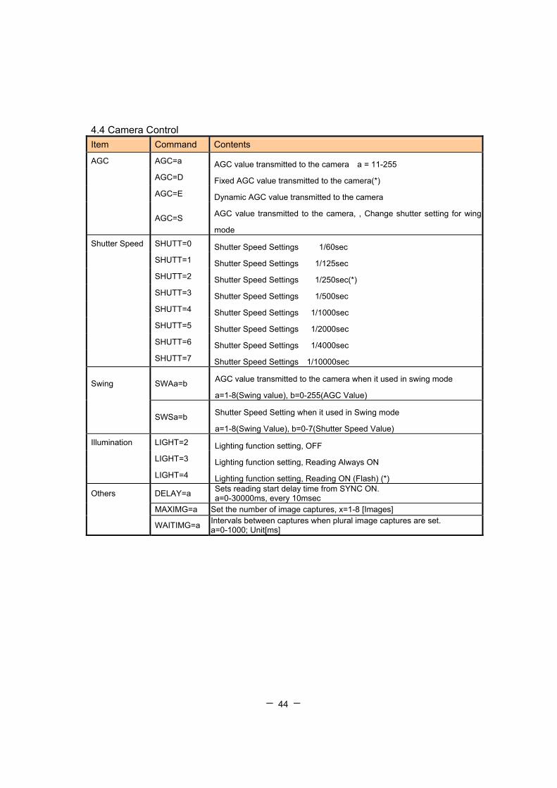
4.4 Camera Control Item Command Contents
AGC AGC=a AGC value transmitted to the camera a = 11-255 AGC=D Fixed AGC value transmitted to the camera(*) AGC=E Dynamic AGC value transmitted to the camera
AGC=S AGC value transmitted to the camera, , Change shutter setting for wing
mode
Shutter Speed SHUTT=0 Shutter Speed Settings 1/60sec SHUTT=1 Shutter Speed Settings 1/125sec SHUTT=2 Shutter Speed Settings 1/250sec(*) SHUTT=3 Shutter Speed Settings 1/500sec SHUTT=4 Shutter Speed Settings 1/1000sec SHUTT=5 Shutter Speed Settings 1/2000sec SHUTT=6 Shutter Speed Settings 1/4000sec SHUTT=7 Shutter Speed Settings 1/10000sec
Swing SWAa=b AGC value transmitted to the camera when it used in swing mode
a=1-8(Swing value), b=0-255(AGC Value)
SWSa=b Shutter Speed Setting when it used in Swing mode
a=1-8(Swing Value), b=0-7(Shutter Speed Value)
Illumination LIGHT=2 Lighting function setting, OFF LIGHT=3 Lighting function setting, Reading Always ON LIGHT=4 Lighting function setting, Reading ON (Flash) (*)
Others DELAY=a Sets reading start delay time from SYNC ON. a=0-30000ms, every 10msec
MAXIMG=a Set the number of image captures, x=1-8 [Images]
WAITIMG=a Intervals between captures when plural image captures are set. a=0-1000; Unit[ms]

- - 45
4.5 Preset Mode Setting Item Command Contents Preset ?pre Confirmation of preset status
PREM=0 Preset Mode 0: Disable preset function(*)
PREM=1 Preset Mode 1: Enable preset function, after power is switched ON, the
first OK read data is registered within the reader as “preset” data.
PREM=2 Preset Mode 2: Enable preset function, the preset data is registered within
flash memory.
SET=PRENa Sets the number of digits of preset data to compare
a: Digits, a=0-100 When set 0: Free digits clrpren Clears the preset digit number SET=PREDa Sets the actual value of the characters to compare against clrpred Clears the preset data characters
4.6 Reference Settings Item Command Contents
Sets Confirmation ? Status Transmission (1st page) ?? Status Transmission (2nd page) ??? Status Transmission (3rd page) ?4 Status Transmission (4th page) ?5 Status Transmission (5th page) ?6 Status Transmission (6th page)
?LF Status for Auto detection
?IMG Status for image output
- - 46
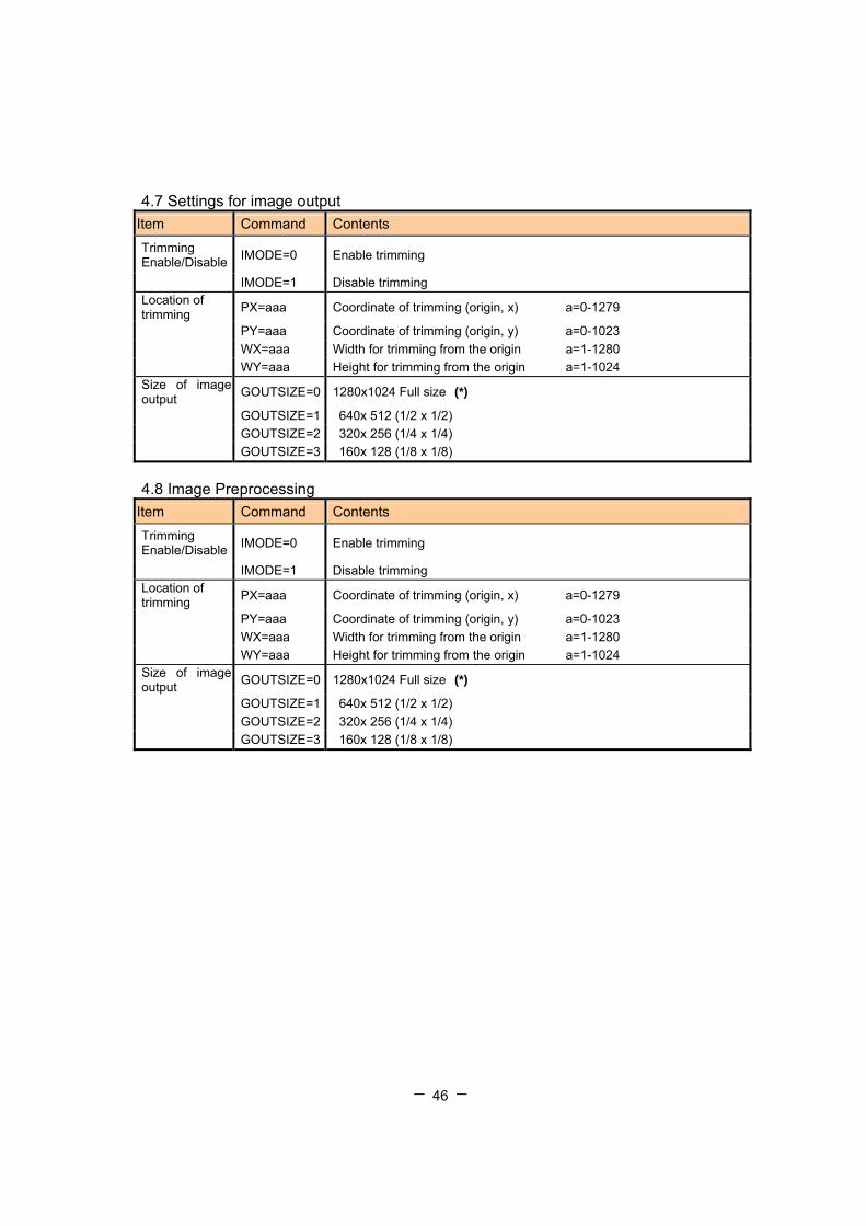
4.7 Settings for image output Item Command Contents Trimming Enable/Disable IMODE=0 Enable trimming
IMODE=1 Disable trimming Location of trimming PX=aaa Coordinate of trimming (origin, x) a=0-1279
PY=aaa Coordinate of trimming (origin, y) a=0-1023 WX=aaa Width for trimming from the origin a=1-1280 WY=aaa Height for trimming from the origin a=1-1024 Size of image output GOUTSIZE=0 1280x1024 Full size (*)
GOUTSIZE=1 640x 512 (1/2 x 1/2) GOUTSIZE=2 320x 256 (1/4 x 1/4) GOUTSIZE=3 160x 128 (1/8 x 1/8)
4.8 Image Preprocessing
Item Command Contents Trimming Enable/Disable IMODE=0 Enable trimming
IMODE=1 Disable trimming Location of trimming PX=aaa Coordinate of trimming (origin, x) a=0-1279
PY=aaa Coordinate of trimming (origin, y) a=0-1023 WX=aaa Width for trimming from the origin a=1-1280 WY=aaa Height for trimming from the origin a=1-1024 Size of image output GOUTSIZE=0 1280x1024 Full size (*)
GOUTSIZE=1 640x 512 (1/2 x 1/2) GOUTSIZE=2 320x 256 (1/4 x 1/4) GOUTSIZE=3 160x 128 (1/8 x 1/8)
- - 47
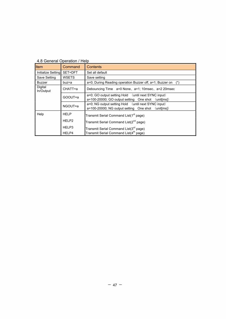
4.8 General Operation / Help Item Command Contents Initialize Setting SET=DFT Set all default Save Setting WSETS Save setting Buzzer buz=a a=0; During Reading operation Buzzer off, a=1; Buzzer on (*) Digital In/Output CHATT=a Debouncing Time a=0 None、a=1; 10msec、a=2 20msec
GOOUT=a a=0; GO output setting Hold (until next SYNC input) a=100-20000; GO output setting One shot (unit[ms])
NGOUT=a a=0; NG output setting Hold (until next SYNC input) a=100-20000; NG output setting One shot (unit[ms])
Help HELP Transmit Serial Command List(1st page) HELP2 Transmit Serial Command List(2nd page) HELP3 Transmit Serial Command List(3rd page) HELP4 Transmit Serial Command List(4th page)

- - 48
4.9 Table of character code
0 1 2 3 4 5 6 7 8 9 A B C D E F
0 NUL DLE SP 0 @ P ` p ー タ ミ
1 SOH DC1 ! 1 A Q a q 。 ア チ ム
2 STX DC2 " 2 B R b r 「 イ ツ メ
3 ETX DC3 # 3 C S c s 」 ウ テ モ
4 EOT DC4 $ 4 D T d t 、 エ ト ヤ
5 ENQ NAK % 5 E U e u ・ オ ナ ユ
6 ACK SYN & 6 F V f v ヲ カ ニ ヨ
7 BEL ETB * 7 G W g w ァ キ ヌ ラ
8 BS CAN ( 8 H X h x ィ ク ネ リ
9 HT EM ) 9 I Y i y ゥ ケ ノ ル
A LF SUB * : J Z j z ェ コ ハ レ
B VT ESC + ; K [ k ォ サ ヒ ロ
C FF FS , < L ¥ l | ャ シ フ ワ
D CR GS - = M ] m ュ ス ヘ ン
E SO RS . > N ^ n " ョ セ ホ ゙
F SI US / ? O _ o DE
L ッ ソ マ ゚
UPPER DATA
L
O
W
E
R
D
A
T
A

- - 49
5.Specifications 5.1 General specifications
Physical Dimensions
- Length 56 mm
- Width 60 mm
- Depth 22 mm (without protrusions)
- Weight approx. 75g
Reading Field *
- Pitch Depends on state of marking
- Skew Depends on state of marking
- Rotation 360 degrees
-Ambient Light Depends on state of marking.
Compatible bar codes
2D codes
Data Matrix (ECC200 ), Maxi Code, PDF417
Micro PDF, QR Code, Micro QR, Composite
1D bar codes
UPC/EAN/JAN, CODE 39, CODE 128,
EAN 128, ITF, CODABAR, Code93, RSS
Camera - Imaging Device : 1/3 inch CMOS
- Color and Monochrome
- The number of effective pixels:
1280(X) x 1024(Y), Approx. 1.3 M pixels
External input and output
- Serial Interface: RS-232C/USB 1.1
- Data form: ASCII
- Transmission speed:1200bps - 115.2kbps
- Digital I/O
Output: 2 (Open corrector)
Input: 2
Power-supply voltage
Rated voltage 5VDC +/- 10%
(Ripple 100mVp-p)
Consumption current : 0.4A
Environment
- Operating temperature range: 0 to 40°C
- Storage temperature range: -20 to 65°C
- Humidity: 35 to 85% RH (non condensing)
- - 50
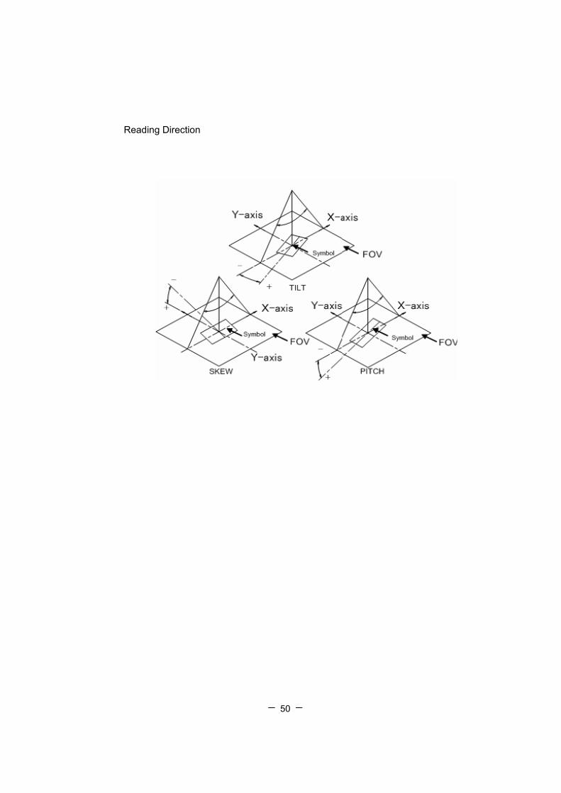
Reading Direction
- - 51
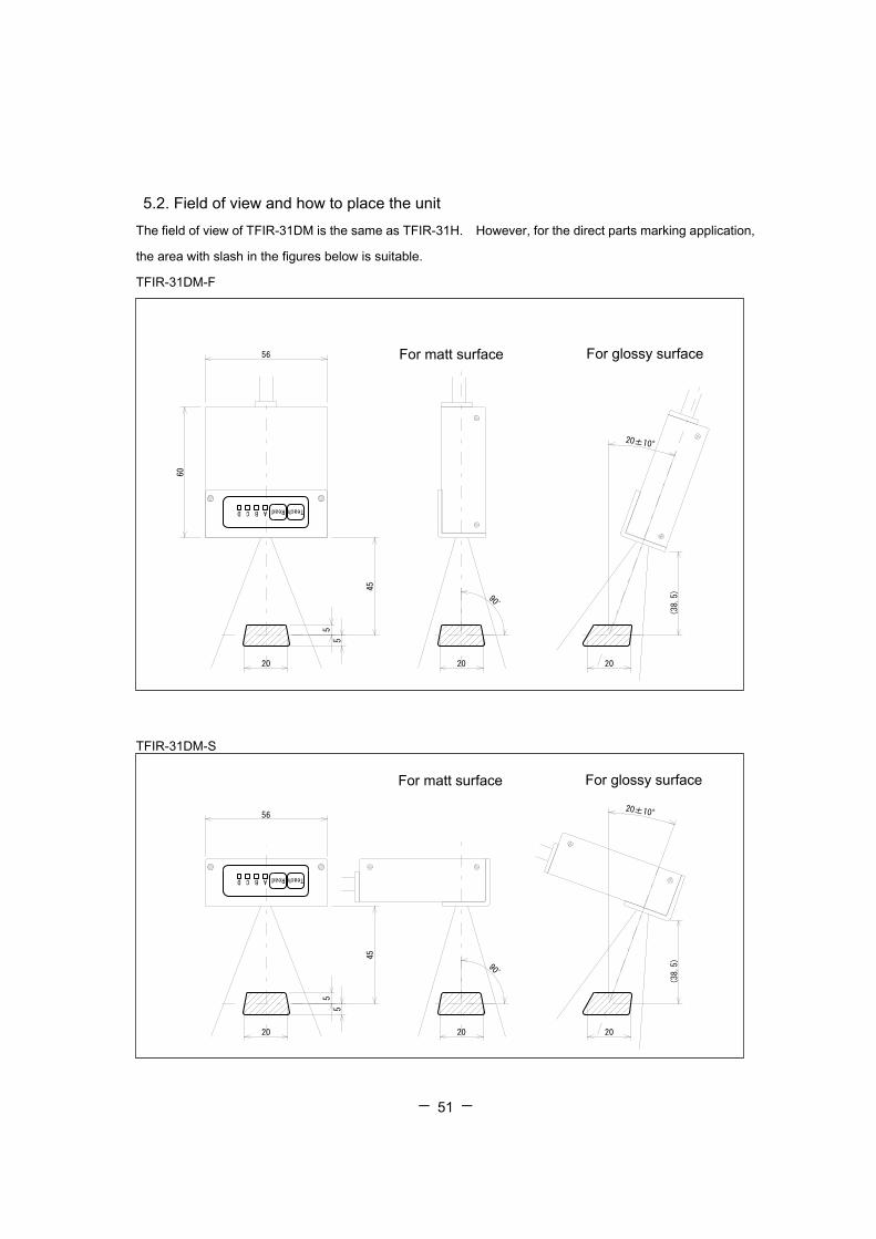
5.2. Field of view and how to place the unit
The field of view of TFIR-31DM is the same as TFIR-31H. However, for the direct parts marking application,
the area with slash in the figures below is suitable.
TFIR-31DM-F
TFIR-31DM-S
ABCD Read Teach
56
60
45
5
5
(38.5)
20±10°
マーキング面に光沢が無い場合 マーキング面に光沢が有る場合
90゚
202020
For matt surface For glossy surface ABCD Read Teach
45
5
5
(38.5)
20±10°56
90゚
マーキング面に光沢が無い場合 マーキング面に光沢が有る場合
20 20 20
For matt surface For glossy surface

- - 52
5.3 Dimensions
5.3.1 F type (Front View)
視野方向 視野方向
読み取り窓(基点)
Y軸
X軸
A B C DReadTeach
13
50
2-M3取付穴 深さ19
22
56
60
11
Reading window (the base point)
Y-axis
X-axis
Direction of view
2-M3 hole for
- - 53
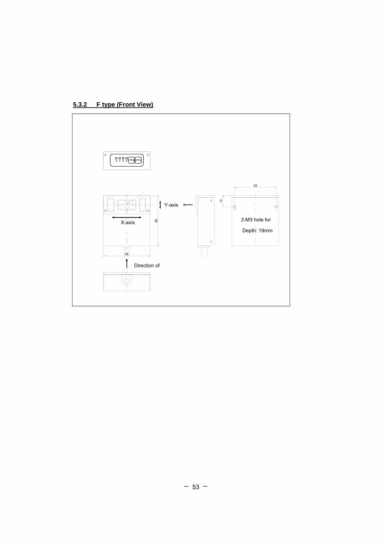
5.3.2 F type (Front View)
視野方向
X軸
ABCD Read Teach
60
56
読み取り窓(基点)
Y軸視野方向
13
50
2-M3取付穴 深さ19
Y-axis
X-axis
Direction of
2-M3 hole for
Depth: 19mm

- - 54
5.5 Interface 1) With Dsub9 connector
Signal Pin # NC 1 SD 2 RD 3 NC 4 GND 5 NC 6 CS 7 RS 8 NC 9
Signal Pin # Vcc 1 GND 2
Host connection:Dsub9 (female)
AC adaptor jack : EIAJ – TypeⅡ
1
5 9
6
1: Inside pin
2: Outside
1950
50
1
5 9
6
1: Inside pin
2: Outside
1950
50

- - 55
2) USB
Pin No Signal Function Directions Color of cable
1 Vcc +5V Red
2 DAT-
Half-duplex
differential
signaling -
In & Out White
3 DAT+
Half-duplex
differential
signaling +
In & Out Green
4 GND Ground Black
Note: for TFIR-31DMU a USB connector plug A is used
4
1
1950

- - 56
3) RS-232C (without connector)
Signal Function Directions Color of cable
Vcc +5V White w/ Red dot
GND Power Return / Signal Earth White w/ Black dot
SD(TXD) Transmitted Data Output Pink w/ Red dot
RD(RXD) Received Data Input Pink w/ Black dot
RS(RTS) Request To Send Output Orange w/ Red dot
CS(CTS) Clear To Send Input Orange w/ Black dot
SYNC IN Synchronous Input Input Yellow w/ Red dot
USER IN For data preset Output Yellow w/ Black dot
OUT GO/NG Output Input Gray w/ Red dot
LED OUT For external illumination Output Gray w/ Black dot
Vcc +5V Orange w/ double Red dot
GND Power Return / Signal Earth Orange w/ double Black dot
SHIELD Frame Ground
“Directions” from the unit to host

- - 57
4) Circuit for inputting and outputting DIO (RS-232C)
4)-1 Synchronous Input
4)- 2 GO/NG output
Black (GND)
White (OUT) Electric Load
GND
Max 50mA
DC5~30V
+
Pink (SYNC)
Black (GND)
Internal circuit
5V
10kΩ
10kΩ
0.01μF
GND
74HC14 (Toshiba)
or similar
470Ω Open Corrector
Internal circuit
- - 58
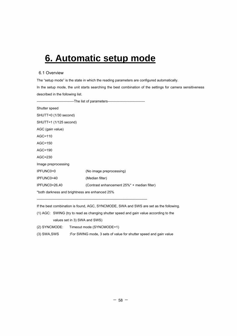
6. Automatic setup mode
6.1 Overview
The “setup mode” is the state in which the reading parameters are configured automatically.
In the setup mode, the unit starts searching the best combination of the settings for camera sensitiveness
described in the following list.
--------------------------------The list of parameters--------------------------------
Shutter speed
SHUTT=0 (1/30 second)
SHUTT=1 (1/125 second)
AGC (gain value)
AGC=110
AGC=150
AGC=190
AGC=230
Image preprocessing
IPFUNC0=0 (No image preprocessing)
IPFUNC0=40 (Median filter)
IPFUNC0=26,40 (Contrast enhancement 25%* + median filter)
*both darkness and brightness are enhanced 25%
-----------------------------------------------------------------------------------------------
If the best combination is found, AGC, SYNCMODE, SWA and SWS are set as the following.
(1) AGC: SWING (try to read as changing shutter speed and gain value according to the
values set in 3) SWA and SWS)
(2) SYNCMODE: Timeout mode (SYNCMODE=1)
(3) SWA,SWS :For SWING mode, 3 sets of value for shutter speed and gain value
- - 59
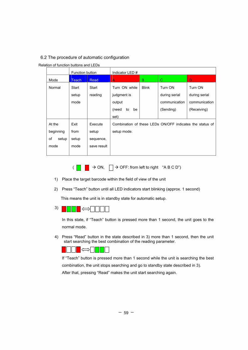
6.2 The procedure of automatic configuration
Relation of function buttons and LEDs
Function button Indicator LED #
Mode Teach Read A B C D
Normal Start
setup
mode
Start
reading
Turn ON while
judgment is
output
(need to be
set)
Blink Turn ON
during serial
communication
(Sending)
Turn ON
during serial
communication
(Receiving)
At the
beginning
of setup
mode
Exit
from
setup
mode
Execute
setup
sequence,
save result
Combination of these LEDs ON/OFF indicates the status of
setup mode.
( ON, OFF: from left to right “A B C D”)
1) Place the target barcode within the field of view of the unit
2) Press “Teach” button until all LED indicators start blinking (approx. 1 second)
This means the unit is in standby state for automatic setup.
3)
In this state, if “Teach” button is pressed more than 1 second, the unit goes to the
normal mode. 4) Press “Read” button in the state described in 3) more than 1 second, then the unit
start searching the best combination of the reading parameter.
If “Teach” button is pressed more than 1 second while the unit is searching the best
combination, the unit stops searching and go to standby state described in 3).
After that, pressing “Read” makes the unit start searching again.

- - 60
5) LED indicators start blinking after the unit finds the best combination of the reading parameters. If the reading rate is 0%, the unit is back to the state described in 3). The ways of blinking show the reading rate with the combination.
6) After the unit finds the combination, there are three ways for the next step
Press “Read” button more than 1 second Save the combination to the flash memory
and go to normal mode
Press “Read” button less than 1 second or press “Teach” Back to standby state
described in (3). Then press “Read” Search the best combination of reading
parameters again.
Press “Read” button less than 1 second or press “Teach” Back to standby state
described in (3). Then press “Teach” more than 1 second Back to Normal mode
*NOTE
• In Auto Detection mode (SYNCMODE=3), “Teach” and “Read” buttons are not
available.
• The code types disabled are not read. This is why the operator has to make sure the
target barcode is enabled or not before running the setup mode..
• In the setup mode, the unit counts the reading rate by using TEST mode parameter
TMN (the number of trials: default is 10)
• After the result turns 0% of reading rate, the combination is not saved even when
“Read” button is pressed more than 1 second. In this case, the unit stars searching
again.
Reading rate 100% (without image preprocessing)
Reading rate 100% (with image preprocessing)
Reading rate under 100%
- - 61
7.Troubleshooting 7.1 The unit does not work while pushing the read trigger switch.
Is power supply voltage within specification?
Power supply voltage should be DC 3V-6V. If the DC voltage is not within the specified
range not only the unit will not operate, but there is a strong possibility of damaging the unit.
Is power supply polarity correct?
When it is connected with reverse polarity, the unit does not operate. In this case there is no
damage happen to the unit.
Is the power rating of the power supply enough?
Unless the power supply capacity is enough, the reader may not operate.
Is the format of serial command correct?
After the unit is turned on, it is ready to receive serial commands. Please be sure to add
[CR] after the serial command which is about to be sent. Simply saying, after input the serial
command, please press “enter”
The serial command “WSETS” is used to save all of settings to the unit’s flash memory.
When serial commands are sent continuously, it is recommended to have at least 500ms
interval between one serial command and another.
Others
With USB interface, sometimes the unit can not work after host PC restarts from standby
mode. Removing the unit in advance is encouraged.
7.2 Barcode Cannot be Read.
Is a code setup correct?
Check the settings of the reader and that the 2D code is enabled
Is reading distance suitable?
Reading may be impossible when the reading distance is outside the working range of
reading depth. Moreover the printing quality of the code may make it non-readable even if it is
within the reading range limits.
Is the surface of the code glossy?
If the surface of the code is glossy, the illumination will be sometimes reflected like a mirror.

- - 62
To avoid this, put the scanner in angle relative to the symbol.
Is the reading window clean?
If the window becomes dirty or stained, the image taken by the reader might not be good
enough for reading. Clean with a lens cleaner or similar anti-scratching (non-abrasive)
method.
Is the print quality of the code good?
Please check whether print quality of the cells, code size, etc. conforms to the standard.

- - 63
7.3 The data does not transmit or the data itself is corrupted.
Is the setup with host computer correct?
Please check whether the baud rate and frame format is the same as that of the host
computer. If frame format differs, it may seem that data is transmitted incorrectly.
Do you set fixed digit for ITF
In some cases, cancellation of significant digits (reading it through with a few digits than a
printed digits) in ITF(Interleaved 2 of 5) might be used. We recommend setting specific digit
of ITF.

- - 64
[Memorandum]

- - 65
Warranty Obligations This warranty obligation is limited to terms set forth below: TOHKEN warrants this
hardware product against defects one year form the date of purchase.
<Warranty Coverage>
1. TOHKEN will repair the product at no charge, for hardware defects occurring
when used in accordance with the manual and catalog, under normal operating
conditions.
2. Warranty is not covered in following cases:
a.) Defects or damage as a result of improper usage or modification.
b.) Defects or damage caused by fire, pollution, abnormal voltage, or natural
disasters, such as earthquake, thunderstorm or flood.
When you are not sure about repairs outside of these terms, please ask your local
representative or the manufacturer.

- - 66
TOHKEN CO., LTD Head quarters
2-7-1 Nishi-Shinjuku, Shinjuku-ku, Tokyo Japan 163-0710 Sales 03-5325-4311 to 4315 Sales Promotion 03-5325-4322
Nagoya office
4-2-12 Meieki, Nakamura-ku, Nagoya Japan 450-0002 Sales 052-565-9091
Osaka office
2-9-1 Higashi-Tenman, Kita-ku, Osaka Japan 530-0044 Sales 06-6353-5476
Fukuoka office
8-36 Hakata-eki Chuogai, Hakata-ku, Fukuoka Japan 812-0012 Sales 092-441-3638
Hitachi office
2-1-10 Hashikabe, Hitachinaka, Ibaragi Japan 312-054 Sales 029-276-9555
Field support department (Technical Center 3)
1-43-2 Tamagawa, Chofu, Tokyo Japan 182-0025 Field support 042-484-5190


