28
VER2.0, March 22, 2006 COMBINED SAFETY SMART CARD 1

VER2.0, March 22, 2006
COMBINED SAFETY SMART CARD
1

SECTION PAGE
1. AUTOMATIC FIRE EXTINGUISHER SYSTEM (AFES BY KIDDE)………………………………….…… 3
2. SINGLE MOVEMENT COMBAT LOCKS………………………. 6
3. EMERGENCY RESCUE WRENCH (BOLT REMOVAL TOOL)………………………………………. 10
4. SINGLE ANCHOR GUNNERS RESTRAINT (SCHROTH)……………………………………………………..…. 11
5. IMPROVED GUNNERS RESTRAINT………………………..… 16
6. PERSONAL RESTRAINT SYSTEM…………………………….. 18
7. EMERGENCY PROCEDURES………………………………….. 22 a. ROLL-OVER DRILLS……………………………………. 24 b. WATER EGRESS…………………………………………. 26
8. SAFETY PRECAUTION (STICKER)…………………………... 29
2

HMMWV (M1114) AUTOMATIC FIRE EXTINGUISHER SYSTEM (KIDDE)
(AFES BY KIDDE) SMART CARD
Operation of the AFES (KIDDE) system in an M1114 presents the following safety concerns: 1. Personnel Injury – Wear the following:
a. Eye protection b. Kevlar helmet c. Protective clothing
2. Warnings on extinguisher label: a. Discharge from extinguisher can freeze skin at less than 6 inches from
extinguisher nozzle. b. Discharging extinguisher can move violently when not secured. c. Before operating vehicle, confirm the Fire Suppression System is in the configuration below:
• The anti-recoil plug is mounted to bracket in both crew and cargo compartment as shown below.
Anti Recoil Plug
• The manual safety lock is in the valve in both crew and cargo compartment as shown below.
Manual Safety Lock
3

3. Noise Level: a. Peak pressure from discharge noise may exceed 140 decibels. b. Wear hearing protection at all times when AFES is activated. 4. Normal Operation: a. When all sensors and extinguishers are properly connected, the control
module SYSTEM OK lamp will show continuous green. b. The control module is located in front of the radio rack. c. AFES is activated with vehicle engine running. AFES is not activated when engine is off.
System OK Lamp
CONTROL MODULE
5. PMCS: (daily)
a. Check all three sensors for continuous green light. b. Two sensors are located in the crew compartment (one curb side and one
street side) and one sensor is located in the cargo area (See enclosed pictures)
SENSOR LAMP
Cargo Area
SENSOR LAMP
Street Side
SENSOR LAMP
Curb Side
4

c. Inspect for adequate AFES system pressure on both crew and cargo extinguishers.
R
TEMP. °F -40 -22 -4 14TEMP. °C -40 -30 -20 -10P min, PSIG 585 620 655 690
d. Inspect for cleanliness of th
clean cloth. Note 1: AFES system. It may not fires, i.e. fuel fires. Note 2: AFES system is NMC if c a flashing green light. Note 3: If a flashing green contro condition, AFES system i Note 4: SMOKING IN A VEHIC ACTIVATE THE SENS DISCHARGE. Note 5: LARGE, HIGHT INTE LIGHTS MAY ACTIVA DISCHARGE.
PRESSURE INDICATO
32 50 68 86 104 122 140 1580 10 20 30 40 50 60 70
730 770 810 850 905 955 1005 1060
e sensors. If sensors are dirty, wipe with a
protect crew members against all types of
ontrol module SYSTEM OK lamp indicates
l module lamp continues to indicate a fault s NMC. Return to DS Maintenance.
LE WITH AFES INSTALLED MAY OR AND CAUSE AFES TO
NSITY, AFTER MARKET SPOT TE SENSOR AND CAUSE AFES TO
5

HMMWV (M1114) Single Movement Combat Locks
SMART CARD
Single Handle Latch and Lock Operating Instructions. 1. To operate the single handle latch and lock from the outside proceed as follows:
CAUTION Exercise caution when opening the exterior
handle to avoid pinching fingers between handle and the overlays.
a. Pull up on exterior handle until the door latch releases. The door will spring. Pull handle to open.
6
Pinch Point
Handle

2. To operate the single handle latch and lock from the inside proceed as follows: a. Using arm nearest the door, place hand on the curved portion of the handle with the hand in the palm down direction. Pull straight back towards the rear of the vehicle. b. While maintaining the pull back force, push down on the curved portion of the handle. The door latch should release. Push door open.
Curved Handle k
Pull Bac
7

3. To engage the combat locks from the inside proceed as follows: a. Using the arm nearest the door, place hand on the curved portion of the handle with the hand in the palm down direction. Pull straight back towards the rear of the vehicle. b. While maintaining the pull back force, rotate the handle up towards the window until it clicks into position. The combat locks are now engaged.
k
Pull Bac
Rotate Up
8

4. To exit the vehicle, with combat locks engaged, in one motion proceed as follows: a. Place hand on the curved portion of the handle and pull straight back towards the rear of the vehicle. b. While maintaining the pull back force, in one swift motion, rotate the handle down and continue pushing down until the door latch releases. Push door open.
Rotate Down
k
Pull Bac
9

HMMWV (M1114/M1151) Emergency Rescue Wrench/Bolt Removal Tool
Procedures: You are removing the bolts 1. Remove emergency rescue wrench from storage position behind right rear passenger seat on the “C” partition. 2. Identify door that allows immediate access to conscious occupants. 3. Locate two groups of three bolts at the rear of each door. Note: One bolt protrudes in each group 4. Remove countersunk bolts first then the protruding one. Complete one group at a time. Remove bolts by turning in a counterclockwise motion until the bolts back out. Note: You should feel the lock fall after removing the third bolt from each group. 5. After removing the second group of bolts, open door with handle. 6. Proceed to next door.
10

HMMWV (M1114) Schroth Single Anchor
Gunner’s Restraint System SMART CARD
1. What it does: a. Keep gunner from being ejected from vehicle during roll-over b. Help stabilize gunner during operation over rough terrain c. Help stabilize gunner during high speed maneuvers Note: These instructions are not intended to replace roll-over drills or hasty evac from this vehicle. They are intended for use in accordance with the gunner’s protection kit and roll-over drills together for added protection. 2. Proper donning of the harness is critical: (see photos below)
a. Orient harness by locating the upper D-ring and bring upper straps over the shoulder per photos #1 & #2.
Upper D-ring
1 2
Photo #
11
Photo #

b. Fit harness per photos #3 & #4.
3 4
c. Connect vertical anch (photo #5 & # 6).
Vertical Ancho
Photo #
or strap to attachment ring on harne
r Strap
Lower Harness Attachment Ring
5
12
Photo #
ss
6
Photo # Photo #
Note: Ensure lower attachment ring is connected in front of gunner’s seat per photo #7.
7 3. Safety Concerns: a. Do not rely on t rollover or vehi Note: The restra being eject into the ve b. Replace the gun c. Emergency rele accomplished u
RQ
Photo #
he restraint systemcle accident.
int system is onlyed from the vehihicle.
ner’s restraint sysase from the restratilizing the rotary
otary Buckle uick Release
Lower Harness Attachment
to prevent injury in the event of a
designed to prevent the gunner from cle; it will not pull the gunner back
tem following an accident. int system should always be buckle quick-release.
Photo #8
13

Note: For emergency release of the rotary buckle quick-release, press the yellow button and turn. The buckle can be turned in either direction per photo #8. 4. Recommendations:
a. Anchor strap can be adjusted as needed; however, any slack in the belt will reduce the effectiveness of the restraint and is not recommended.
If your vehicle is equipped with the Improved Gunner’s Restraint, follow the instructions below.
14

HMMWV (M1114) Improved Gunner’s
Restraint System SMART CARD
1. Improvements:
a. The Improved Gunner’s Restraint is distinguished by a push-button quick release, swivel, and adjustable “tail” strap.
1. Quick release on “tail” strap allows gunner to quickly exit the
vehicle without having to drop the harness. 2. The swivel prevents “tail” strap from twisting/binding.
Swivel
Push-Button Quick Release
3. The adjustable “tail” strap allows taller gunners to lengthen the
straps for easier access, but still allow shorter gunners to keep the strap tight enough to provide effective protection.
Adjustment Point Adjustment
Point
15

b. Donning of the harness is the same as the original with the exception of attaching the push-button quick release to the anchor strap.
Push-Button Quick Release
Anchor Strap
c. Emergency release from the restraint system can also be accomplished utilizing the rotary buckle.
Rotary Buckle Quick Release
Note: For emergency release of the rotary buckle quick-release, press
the yellow button and turn. The buckle can be turned in either direction per photo above. 16

HMMWV (M1114) Personal
Restraint System
1. Design: a. The new restraint system has a lap strap and shoulder strap that are inserted into the buckle separately. (See photos below) b. Both can be released at the same time by lifting the lever on the buckle.
c. The lap strap and shoulder strap each terminate in a webbing retractor.
Lifting Lever Lap Strap
Shoulder Strap
2. Operation:
a. Insert the lap strap into the lower slot on the buckle, ensuring it is locked in place.
b. Insert the shoulder strap into the upper slot on the buckle, ensuring it is locked in place.
Note: The retractors will automatically lock whenever they sense strap or vehicle acceleration in excess of preset levels. Once activated, the retractor will remain locked as long as there is tension in the strap. Relaxing the pressure on the straps will allow retractors to unlock.
17

Upper Webbing Retractor Lower
Webbing Retractor
c. Further adjustments are made using the buckle as follows:
1. To lengthen: Locate the adjusting knob on the buckle and pull up
until the buckle is free to slide. Move the buckle to the desired position and release the adjusting knob, ensuring that it locks into place.
Adjusting Knob
18
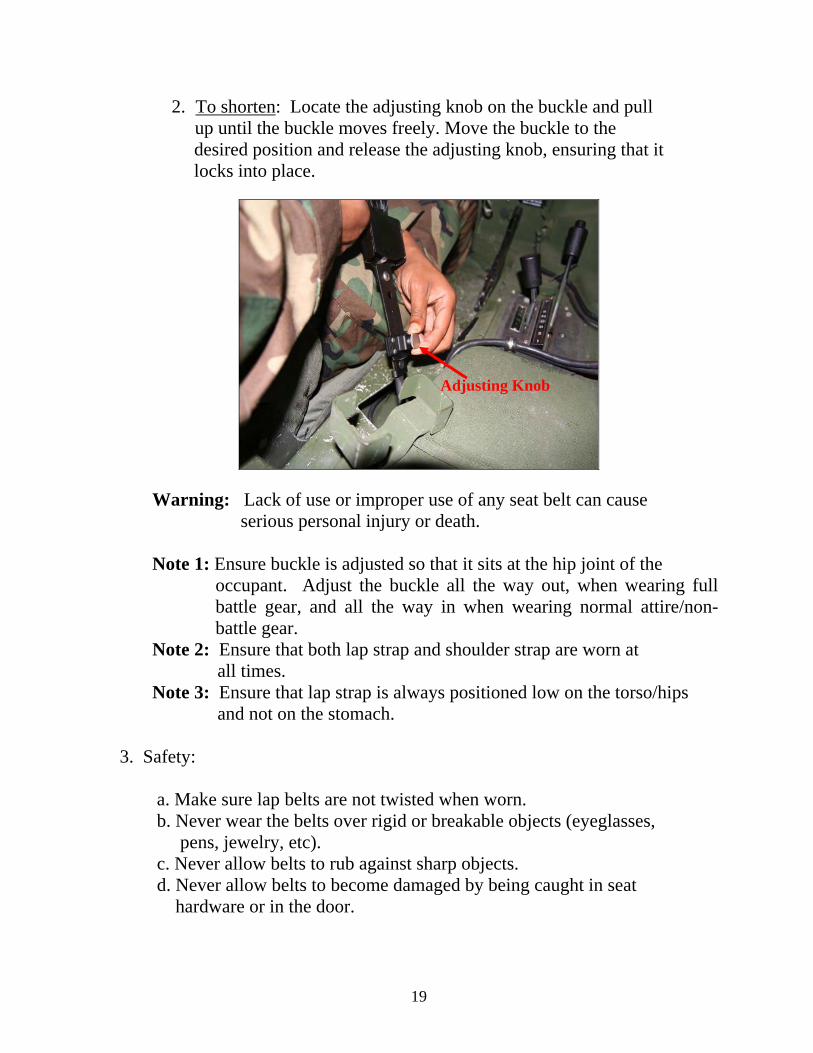
2. To shorten: Locate the adjusting knob on the buckle and pull up until the buckle moves freely. Move the buckle to the
desired position and release the adjusting knob, ensuring that it locks into place.
Adjusting Knob
Warning: Lack of use or improper use of any seat belt can cause serious personal injury or death. Note 1: Ensure buckle is adjusted so that it sits at the hip joint of the
occupant. Adjust the buckle all the way out, when wearing full battle gear, and all the way in when wearing normal attire/non-battle gear.
Note 2: Ensure that both lap strap and shoulder strap are worn at all times. Note 3: Ensure that lap strap is always positioned low on the torso/hips and not on the stomach. 3. Safety: a. Make sure lap belts are not twisted when worn. b. Never wear the belts over rigid or breakable objects (eyeglasses, pens, jewelry, etc). c. Never allow belts to rub against sharp objects. d. Never allow belts to become damaged by being caught in seat hardware or in the door. 19

20
4. Maintenance (Inspection, Modification and Cleaning): a. Check seat belts once a month: 1. Look for cuts, tears, abrasion and other damage. 2. Any of the above will greatly reduce effectiveness and must be replaced. 3. Make sure buckle is free of any obstructions and locks securely. b. Modifications: 1. Modified belts that have been re-sewn lose their strength and are dangerous in an accident. 2. Never modify, disassemble or repair the belts yourself. 3. Use of non-authorized parts and accessories can reduce the effectiveness of the restraint system. c. Cleaning: a. Use soap and warm water only. b. Do not use solvents. c. Do not dry belt in the sun or near a radiator. Warning: Improper cleaning or drying of the restraint system can weaken it, can reduce its effectiveness and can result in serious personal injury or death. The M1114 Personal Restraint System is installed for your protection – Use it!

HMMWV (M1114) Emergency Procedures Performance Measures
GTA 55-03-030 FOUO
WARNING Never attempt to leap from a rolling vehicle. It may roll over you. Ensure that the
vehicle has stopped its roll before moving. Upon complete evacuation of all personnel, vehicle should be inspected for fire hazards such as leaking oil, fuel, ammunition and hydraulic fluid. Use the portable fire extinguisher when inspecting vehicle for leaks in case of fire, which could cause injury or death. If hazardous/explosive materials are involved, driver should take actions according to the DD Form 836 accompanying load. Notify rescue personnel and remain at evacuation distance while securing accident site.
PREVENTIVE MEASURES: Slow Down - Watch Sharp Curves and Steep Slopes - Curves and slopes generate centrifugal forces that act sideways on the vehicle, increasing the chance of rollover. Avoid panic-don’t jerk the steering wheel: Many rollovers occur when the driver panics / jerks the steering wheel during an emergency. At highway speed, jerking the steering wheel can cause loss of control and the vehicle may slide sideways and roll over. Know proper maneuvering: If you drive off the roadway, gradually reduce speed. Ease your vehicle back onto the roadway at a safe speed. Use caution on rural roads/roads with soft or no shoulders: When a vehicle goes off a road, the vehicle can overturn when it strikes a ditch or embankment, or is tripped by soft soil. Pay attention to vehicle condition, tire pressure and loading: Pay particular attention to tire condition and air pressure during PMCS to reduce potential hazards. Worn / improperly inflated tires increase your risk of rollover. Don’t overload the vehicle. The M1114 payload is 2300 lbs. This includes the passengers, winch, gunners protection kit, spare tire, weapons, and all cargo! Keep the Vehicle Center of Gravity Low. Load heavier items low in the vehicle. Increasing the height of the vehicle's center of gravity increases your risk of roll over. Secure the Load. Improperly secured loads can shift and increase the chance of rollover-and become hazards inside the vehicle during a rollover. Trailer Towing. Vehicles towing trailers are much more prone to roll over, especially in curves and during sudden steering maneuvers, as a result of the exaggerated motion of the trailer. 21

22
Work As A Team: Maintain crew integrity - train as a team. Communicate with the driver-tell the driver what is to the left, right, rear, and overhead. Your gunner is your eyes and ears! The gunner may be the only crew member capable of seeing around the entire vehicle. Use the vehicle intercom system to pass visual information to the driver, but rehearse shouted voice commands and hand signals in case the intercom is inoperative. Avoid hazards-use a ground guide whenever possible. Wear seatbelts. Survive the rollover! Use combat locks-safely –combat locks help keep the doors closed in a crash, but are a hazard near water! Unlock combat door locks when near water (enemy situation permitting). Know how to get-out. Rehearse vehicle evacuation as if only one exit is available.
• Combat door locks on the M1114 Up armored HMMWV are designed to keep the enemy out. When locked they also make it extremely difficult for rescuers to enter the vehicle!
• Accident damage may also jam the door locking devices, making them impossible to open.
• If the doors cannot be opened by occupants or rescue team members and the vehicle is inverted in water too deep to allow air in the vehicle, the likelihood of drowning is high.
• In this case, rescuers must immediately attempt to roll the vehicle on its side using all available means (tow straps, rope, winch cables, etc.) to gain access to the turret.
• Leaders must decide, based on the enemy situation, whether or not to keep the doors locked when operating near any body of water (bridges over/roads adjacent to any canal, river, lake, pond, etc.).

ROLLOVER DRILL TASK STEPS AND PERFORMANCE MEASURES NOTE: The driver and the vehicle commander must be wearing seat belts. 1. Execute Rollover Drill: a. Driver--
(1) Releases the accelerator. (2) Yells "Rollover!”. (3) Keeps hands on the steering wheel tucks head and chin into chest and braces for an impact. (4) Shuts down the engine.
b. Vehicle Commander--
(1) Yells “Rollover!”. (2) Uses left hand and arm to grab and hold the gunners' legs (3) Tucks head and chin into chest and braces for an impact. (4) Plants feet firmly on the floor while holding onto a stationary object.
c. Gunner--
(1) Yells, "Rollover." (2) Pushes/pull self down into vehicle. (3) Tucks head and chin into chest and braces for an impact. (4) Plants feet firmly on the floor while holding onto a stationary object.
2. After the rollover has stopped: a. Driver--
(1) Checks for injuries and seeks medical attention. (2) Disconnects headset. (3) Releases seatbelt; uses caution if upside down. (4) Assists other crew members; provides first aid. (5) Unlocks combat door locks. (6) Exits the vehicle. (7) Checks for fire. (8) Activates fire extinguisher as needed. (9) Helps provide security. (10) Assists in recovering weapon, ammunition, and sensitive items.
23

24
(11) Assists in vehicle recovery. b. Vehicle Commander--
(1) Checks for injuries and seeks medical attention, as needed. (2) Radios for help/reports the accident to higher HQs. (3) Disconnects headset. (4) Releases seatbelt; uses caution if upside down. (5) Assists other crew members; provides first aid. (6) Unlocks combat door locks. (7) Exits vehicle. (8) Establishes security. (9) Accounts for weapons ammunition, and sensitive items. (10) Assists in vehicle recovery.
c. Gunner--
(1) Checks for injuries and seeks medical attention. (2) Disconnects the headset plug. (3) Releases seatbelt; uses caution it upside down. (4) Assists other crew members: provides first aid. (5) Clears and checks weapon for serviceability. (6) Dismounts weapon as directed. (7) Exits vehicle. (8) Establishes security. (9) Accounts for weapons, ammunition, and sensitive items. (10) Assists in vehicle recovery.
MEDEVAC Request Line 1: 6-digit UTM grid location of pick-up site. Line 2: Radio frequency, call sign and suffix of requesting personnel. Line 3: Number of patients by precedence: Urgent, Priority, and Routine. Urgent – loss of life or limb within 2 hours. Priority – loss of life or limb within 4 hours. Routine – evacuation within 24 hours. Line 4: Special equipment required. As applicable, express either none, hoist, or stokes litter. Line 5: # of patients by type (litter / ambulatory). Line 6: Security of pick-up site (What possible / known threat is in the area?). Line 7: Method of marking pick-up site (near / far recognition devices). Line 8: Patient nationality and status (Coalition Military, US Contractor, non-US Contractor, EPW). Line 9: NBC Contamination.
Unlock combat door locks when operating near water if the enemy
situation permits.

WATER EGRESS DRILL TASK STEPS AND PERFORMANCE MEASURES 1. When water entry is imminent-- a. Driver--
(1) Releases the accelerator. (2) Yells “WATER!” (3) Keep hands on the steering wheel with extended but not locked arms, tucks head and chin into chest and braces for an impact.
b. Vehicle Commander--
(1) Yells “WATER!” (2) Uses left hand and arm to grab and hold the gunners' legs. (3) Unlocks combat door locks prior to impact. (4) Tucks head and chin into chest and braces for impact. (5) Plants feet firmly on the floor while holding onto a stationary object.
c. Gunner--
(1) Yells “WATER!” (2) Pushes/pulls self down into vehicle. (3) Tucks head and chin into chest and brace for impact. (4) Plants feet firmly on the floor while holding onto a stationary object. (5) Unlocks combat door lock.
When the vehicle is stabilized: a. Driver--
(1) Unlocks combat door lock. (2) Shuts down the engine. (3) Disconnects headset. (4) Releases seatbelt; uses caution if upside down. (5) Checks for injuries and seeks Medical attention. (6) Assists other crew members; provides first aid. (7) Identifies an escape route and estimates water depth. (8) Decides whether to remove LBE, body armor, and helmet. (9) Exits the vehicle. (10) Get to safest shore. (11) Accounts for occupants. (12) Helps provide security. (13) Assists in recovering weapons, ammunition, and sensitive items. (14) Assists in vehicle recovery.
25

26
b. Vehicle Commander -- (1) Disconnects headset. (2) Releases seatbelt; uses caution if upside down. (3) Checks for injuries and seeks Medical attention. (4) Assists other crew members; provides first aid. (5) Identifies an escape route and estimates water depth. (6) Decides whether to remove LBE, body armor, and helmet. (7) Exits the vehicle. (8) Get to safest shore. (9) Accounts for occupants. (10) Establishes security. (11) Assists in recovering weapons, ammunition, and sensitive items. (12) Assists in vehicle recovery.
c. Gunner --
(1) Disconnects headset. (2) Releases seatbelt; uses caution if upside down. (3) Checks for injuries and seeks medical attention. (4) Clears and checks the weapon for serviceability. (5) Identifies an escape route and estimates water depth. (6) Decides whether to remove LBE, body armor, and helmet. (7) Exits the vehicle. (8) Get to safest shore. (9) Accounts for occupants. (10) Establishes security. (11) Assists in recovering weapons, ammunition, and sensitive items. (12) Assists in vehicle recovery.
WATER RESCUE / RECOVERY 1. Secure the accident site. 2. Stay in contact with the vehicle. Hold onto the vehicle and kick/swim to high point in buddy teams. 3. Rescuers tie a rope/cable to the vehicle to aid in rescue. 4. Open doors and hatches. 5. If doors and hatches are not accessible, rescuers must immediately use all available means to turn the vehicle on its side to gain access to the turret. 6. Seek out the highest point on/in the vehicle. 7. Ensure that all survivors have air and are able to breathe. 8. Check for other injuries and apply first aid. 9. Carefully move injured personnel to the highest point on the vehicle. 10. Remove excess equipment, to include body armor in deep water.

27
11. Evacuate from vehicle high point to safest location, depending on: • enemy situation • water level and flow • water temperature • distance to waters edge • anticipation of rescue
M1114 Data: Curb Weight: 9800 Lbs/4447 kg Payload: 2300 Lbs/1043 kg Gross Weight: 12,100 Lbs/5489 kg Gross Front Axle: 5300 Lbs/2404 kg Gross Rear Axle: 7000 Lbs/3175 kg Max Towed Load: 4200 Lbs/3175 kg
Max Safe Speed depends on road / trail conditions. Use Your Head! Combat Loading the M1114: The M1114 safely carries up to 2300 lbs, including the crew, fuel and equipment. Don’t overload the vehicle! Secure loads as close to the vehicle centerline as possible. Report the Incident/Accident 1. Who (Unit, Individual)? 2. What (Accident or Combat)? 3. Where (6-digit UTM grid)? 4. How ( What caused the rollover, speed, visibility, cause of injuries or deaths)? 5. Follow up initial report ASAP with information regarding:
a. Weather conditions b. Seatbelts worn by each occupant c. Fatigue/sleep prior to the accident d. Was the driver able to see the hazard/other vehicle? e. Operator training/experience/license
6. Complete Accident Report Form (DA Form 285 AGR) and forward to higher HQs Information provided by: U.S. Army Transportation School Army Driver Standardization Office (ADSO) 705 Read Street Ft Eustis, VA 23604

WARNING: At Gross Vehicle Weight (GVW) rapid steering action at speeds as low as 40 MPH increases your likelihood of a Roll-over (GVW is an Unloaded M1114 plus 4 crew with basic
gear). Road conditions such as sand, debris, gravel or rain will further reduce stability.
SMART CARD/GTA
28
M1114 UAHMMWV
ROLL-OVER PRECAUTION SMART CARD
Combined Safety Smart Card provided by: U.S. Army TACOM, New Equipment Training SFC Carr, Terrence, AMSTA-LC-LFT 6501 E. 11 Mile Rd. Bldg 219 Warren, MI 48397-5000 [email protected]
CAUTION: Commanders must assess risk when vehicles are overloaded, or cargo is placed high in the vehicle, or traveling at speeds in excess of 40 mph.
Authorized GVW is 12,100 pounds.
CONTRIBUTING FACTORS TO ROLL-OVER *** Cargo placed high in vehicle *** Drivers Inexperience/Lack of Training ***
*** Overloading *** Road Conditions *** ACTIONS TO REDUCE POTENTIAL ROLL-OVER
*** Conduct Driver’s Training *** Stay Within Recommended Payloads *** *** Place and Secure Cargo as low as possible in the vehicle ***
*** Reduce Speed when Anticipating a Rapid Maneuver *** *** Maintain Tire Pressures of 40 psi front / 50 psi rear ***
** GVW is an Unloaded M1114 plus 4 crew with basic gear = 12,100 .lbs. **
Stopping Distance at 60 MPH 40 MPH GVW
GVW 13 Vehicle Lengths GVW+2000 lbs. 15 Vehicle Lengths
WARNING: At 60 MPH on smooth dry pavement an overloaded M1114 has a braking distance of 15 vehicle lengths, compared to 13 vehicle lengths at GVW. Road conditions such as
sand, debris, gravel or rain will further increase stopping distances.


