Datasheet G150XNE-L01 avnet-integrated.eu Bezel Embedded Board/ AD Driving solution Storage Wireless Software Housing Cover Lens Touch Sensor Bonding/Optical/Tape TFT display Backlight Driver Computer-on-Module Memory More Value! If you require a touch panel and/or mechanical integration, please scan the QR code or click the URL: avnet-integrated.eu/products/displays/colour-tft-displays/
Transcript
DatasheetG150XNE-L01
avnet-integrated.eu
Bezel
Embedded Board/ AD Driving solution
StorageWirelessSoftware
Housing
Cover Lens
Touch Sensor
Bonding/Optical/Tape
TFT display
Backlight Driver
Computer-on-ModuleMemory
More Value!If you require a touch panel and/or mechanical integration, please scan the QR code or click the URL:avnet-integrated.eu/products/displays/colour-tft-displays/
PRODUCT SPECIFICATION
Version 3.0 7 Mar 2017 1 / 29
The copyright belongs to INNOLUX. Any unauthorized use is prohibited.
Customer: Common
APPROVED BY SIGNATURE
Name / Title Note
Please return 1 copy for your confirmation with your signature and comments.
□ Tentative Specification
□ Preliminary Specification
■ Approval Specification
MODEL NO.: G150XNE SUFFIX: L01
Approved By Checked By Prepared By
阮泰郎阮泰郎阮泰郎阮泰郎 林秋森林秋森林秋森林秋森 吳承旻吳承旻吳承旻吳承旻
avnet-integrated.eu
PRODUCT SPECIFICATION
Version 3.0 7 Mar 2017 2 / 29
The copyright belongs to INNOLUX. Any unauthorized use is prohibited.
- CONTENTS - REVISION HISTORY ------------------------------------------------------- 3 1. GENERAL DESCRIPTION ------------------------------------------------------- 4 1.1 OVERVIEW 1.2 FEATURES 1.3 APPLICATION 1.4 GENERAL SPECIFICATIONS 1.5 MECHANICAL SPECIFICATIONS 2. ABSOLUTE MAXIMUM RATINGS ------------------------------------------------------- 6 2.1 ABSOLUTE RATINGS OF ENVIRONMENT 2.2 ELECTRICAL ABSOLUTE RATINGS 2.2.1 TFT LCD MODULE 2.2.2 BACKLIGHT UNIT 3. ELECTRICAL CHARACTERISTICS ------------------------------------------------------- 8 3.1 TFT LCD MODULE 3.2 BACKLIGHT UNIT 4. BLOCK DIAGRAM ------------------------------------------------------- 11 4.1 TFT LCD MODULE 5. INPUT TERMINAL PIN ASSIGNMENT ------------------------------------------------------- 12 5.1 TFT LCD MODULE 5.2 BACKLIGHT UNIT 5.3 COLOR DATA INPUT ASSIGNMENT 6. INTERFACE TIMING ------------------------------------------------------- 15 6.1 INPUT SIGNAL TIMING SPECIFICATIONS 6.2 POWER ON/OFF SEQUENCE 6.3 SCANNING DIRECTION 7. OPTICAL CHARACTERISTICS ------------------------------------------------------- 19 7.1 TEST CONDITIONS 7.2 OPTICAL SPECIFICATIONS 8. RELIABILITY TEST CRITERIA ------------------------------------------------------- 23 9. PACKAGING ------------------------------------------------------- 24 9.1 PACKING SPECIFICATIONS 9.2 PACKING METHOD 9.3 UNPACKING METHOD 10. DEFINITION OF LABELS ------------------------------------------------------- 26 11. PRECAUTIONS ------------------------------------------------------- 27 11.1 ASSEMBLY AND HANDLING PRECAUTIONS 11.2 SAFETY PRECAUTIONS 12. MECHANICAL CHARACTERISTICS ------------------------------------------------------- 28
avnet-integrated.eu
PRODUCT SPECIFICATION
Version 3.0 7 Mar 2017 3 / 29
The copyright belongs to INNOLUX. Any unauthorized use is prohibited.
REVISION HISTORY
Version Date Section Description
Ver. 3.0
07 Mar 2017 All Approval Specification was first issued.
avnet-integrated.eu
PRODUCT SPECIFICATION
Version 3.0 7 Mar 2017 4 / 29
The copyright belongs to INNOLUX. Any unauthorized use is prohibited.
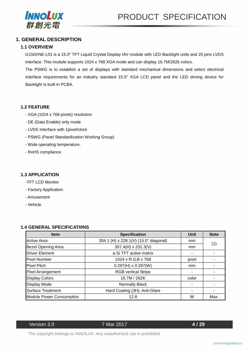
1. GENERAL DESCRIPTION 1.1 OVERVIEW
G150XNE-L01 is a 15.0” TFT Liquid Crystal Display IAV module with LED Backlight units and 20 pins LVDS
interface. This module supports 1024 x 768 XGA mode and can display 16.7M/262k colors.
The PSWG is to establish a set of displays with standard mechanical dimensions and select electrical
interface requirements for an industry standard 15.0” XGA LCD panel and the LED driving device for
Backlight is built in PCBA.
1.2 FEATURE
- XGA (1024 x 768 pixels) resolution
- DE (Data Enable) only mode
- LVDS Interface with 1pixel/clock
- PSWG (Panel Standardization Working Group)
- Wide operating temperature.
- RoHS compliance
1.3 APPLICATION
-TFT LCD Monitor
- Factory Application
- Amusement
- Vehicle
1.4 GENERAL SPECIFICATI0NS
Item Specification Unit Note
Active Area 304.1 (H) x 228.1(V) (15.0” diagonal) mm
Bezel Opening Area 307.4(H) x 231.3(V) mm (1)
Driver Element a-Si TFT active matrix - -
Pixel Number 1024 x R.G.B x 768 pixel -
Pixel Pitch 0.297(H) x 0.297(W) mm -
Pixel Arrangement RGB vertical Stripe - -
Display Colors 16.7M / 262K color -
Display Mode Normally Black - -
Surface Treatment Hard Coating (3H), Anti-Glare - -
Module Power Consumption 12.8 W Max.
avnet-integrated.eu
PRODUCT SPECIFICATION
Version 3.0 7 Mar 2017 5 / 29
The copyright belongs to INNOLUX. Any unauthorized use is prohibited.
1.5 MECHANICAL SPECIFICATIONS Item Min. Typ. Max. Unit Note
Horizontal(H) 326.0 326.5 327.0 mm
Vertical(V) 253.0 253.5 254.0 mm (1)
Module Size
Depth(D) 8.6 9.1 9.6 mm (1)(2)
Horizontal 307.1 307.4 307.7 mm - Bezel Area
Vertical 231.0 231.3 231.6 mm
Horizontal - 304.1 - mm Active Area
Vertical - 228.1 - mm
Weight - 960 1000 g
Note (1) Please refer to the attached drawings for more information of front and back outline dimensions.
Note (2) The depth is without connector.
+/- 0.5mm
avnet-integrated.eu
PRODUCT SPECIFICATION
Version 3.0 7 Mar 2017 6 / 29
The copyright belongs to INNOLUX. Any unauthorized use is prohibited.
2. ABSOLUTE MAXIMUM RATINGS 2.1 ABSOLUTE RATINGS OF ENVIRONMENT
Value Item Symbol
Min. Max. Unit Note
Operating Ambient Temperature TOP -30 +80 ℃ (1)(2)(3)
Storage Temperature TST -40 +80 ℃ (1)(2)(3)
Note (1) Temperature and relative humidity range is shown in the figure below.
(2) 90 %RH Max. (Ta < 40℃).
(3) Wet-bulb temperature should be 39℃ Max.
10
100
80 60 -20 40 0 20 -40
80
40
60
20
Temperature (ºC)
Operating Range
Relative Humidity (%RH)
Storage Range
avnet-integrated.eu
PRODUCT SPECIFICATION
Version 3.0 7 Mar 2017 7 / 29
The copyright belongs to INNOLUX. Any unauthorized use is prohibited.
2.2 ELECTRICAL ABSOLUTE RATINGS
2.2.1 TFT LCD MODULE Value Item Symbol
Min. Max. Unit Note
Power Supply Voltage VCC -0.3 4 V (1)
2.2.2 BACKLIGHT UNIT
Value Item Symbol
Min. Max. Unit Note
Converter Voltage Vi -0.3 18 V (1) , (2)
Enable Voltage EN --- 5.5 V
Backlight Adjust Dimming --- 5.5 V
Note (1) Permanent damage to the device may occur if maximum values are exceeded. Function operation
should be restricted to the conditions described under Normal Operating Conditions.
Note (2) Specified values are for lamp (Refer to 3.2 for further information).
avnet-integrated.eu
PRODUCT SPECIFICATION
Version 3.0 7 Mar 2017 8 / 29
The copyright belongs to INNOLUX. Any unauthorized use is prohibited.
3. ELECTRICAL CHARACTERISTICS 3.1 TFT LCD MODULE
Value Parameter Symbol
Min. Typ. Max. Unit Note
Power Supply Voltage VCC 3.0 3.3 3.6 V -
Ripple Voltage VRP - - 100 mVp-p
Rush Current IRUSH - - 2.0 A (2)
White - 800 960 mA (3)a Power Supply Current
Black lcc
- 670 800 mA (3)b
LVDS differential input voltage Vid 200 - 600 mV
LVDS common input voltage Vic 1.0 1.2 1.4 V
“H” Level VIH - - 100 mV - Differential Input Voltage for LVDS Receiver Threshold “L” Level VIL -100 - - mV -
Terminating Resistor RT - 100 - Ohm -
Note (1) The module should be always operated within above ranges.
Note (2) Measurement Conditions:
470μs
+3.3V
GND
0.9 VCC
0.1 VCC
R1
(High to Low) (Control Signal)
+12V
SW Q2
C1
1uF
VCC
+3.3V
2SK1470
Q1 2SK1475
47K
R2
1K
VR1 47K C2
0.01uF
C3
1uF FUSE (LCD Module Input)
avnet-integrated.eu
PRODUCT SPECIFICATION
Version 3.0 7 Mar 2017 9 / 29
The copyright belongs to INNOLUX. Any unauthorized use is prohibited.
Note (3) The specified power supply current is under the conditions at VDD =3.3V, Ta = 25 ± 2 ℃, DC
Current and fv = 60 Hz, whereas a power dissipation check pattern below is displayed.
3.2 BACKLIGHT UNIT Ta = 25 ± 2 ℃
Value Parameter Symbol Min. Typ. Max.
Unit Note
Converter Power Supply Voltage Vi 10.8 12.0 13.2 V
Converter Power Supply Current Ii 0.5 0.65 0.8 A @ Vi = 12V (Duty 100%)
Backlight Power Consumption PBL - 7.8 9.6 W @ Vi = 12V (Duty 100%)
Backlight on 2.0 3.3 5.0 V EN Control Level
Backlight off -
0 --- 0.8 V PWM High Level 2.0 3.3 5.0 V PWM Dimming Control
Level PWM Low Level -
0 - 0.15 V PWM Dimming Control Duty Ratio - 1 - 100 % @200Hz
PWM Dimming Control Frequency fPWM 190 200 20k Hz (2)
LED Life Time LL 50,000 70,000 - Hrs (3)
Note (1) LED current is measured by utilizing a high frequency current meter as shown below:
Note (2) At 20k Hz PWM control frequency,duty ratio range is restricted from 20% to 100%.
Note (3) The lifetime of LED is estimated data and defined as the time when it continues to operate under
the conditions at Ta = 25 ±2 ℃ and Duty 100% until the brightness becomes 50% of its ≦
original value. Operating LED under high temperature environment will reduce life time and lead to
color shift.
Active Area
a. White Pattern
Active Area
b. Black Pattern
Power Supply
Converter LED
Backlight
Unit
Vi, Ii
GND
Input Power
PBL
avnet-integrated.eu
PRODUCT SPECIFICATION
Version 3.0 7 Mar 2017 10 / 29
The copyright belongs to INNOLUX. Any unauthorized use is prohibited.
Power sequence and control signal timing are shown in the following figure
Note:::: While system is turned ON or OFF, the power sequences must follow as below descriptions
Turn ON sequence: Vi(+12V) → EN → Dimming
Turn OFF sequence: Dimming → EN → Vi(+12V)
Note (4)
50ms>Tr>20ms
minm
Vi(+12V)
GND
0.9 VCC
0.1 VCC
avnet-integrated.eu
PRODUCT SPECIFICATION
Version 3.0 7 Mar 2017 11 / 29
The copyright belongs to INNOLUX. Any unauthorized use is prohibited.
4. BLOCK DIAGRAM 4.1 TFT LCD MODULE
TFT LCD PANEL
(1024x3x768)
DATA DRIVER IC
SC
AN
DR
IVE
R IC
DC/DC CONVERTER &
REFERENCE VOLTAGE
INP
UT
CO
NN
EC
TO
R
RX0(+/-)
RX1(+/-)
RX2(+/-)
RX3(+/-)
RXCLK(+/ -)
LVDS
RECEIVER
VCC
GND
SEL68
LR/UD
Converter LED BACKLIGHT UNIT
CONVERTER CONNECTOR Vi
avnet-integrated.eu
PRODUCT SPECIFICATION
Version 3.0 7 Mar 2017 12 / 29
The copyright belongs to INNOLUX. Any unauthorized use is prohibited.
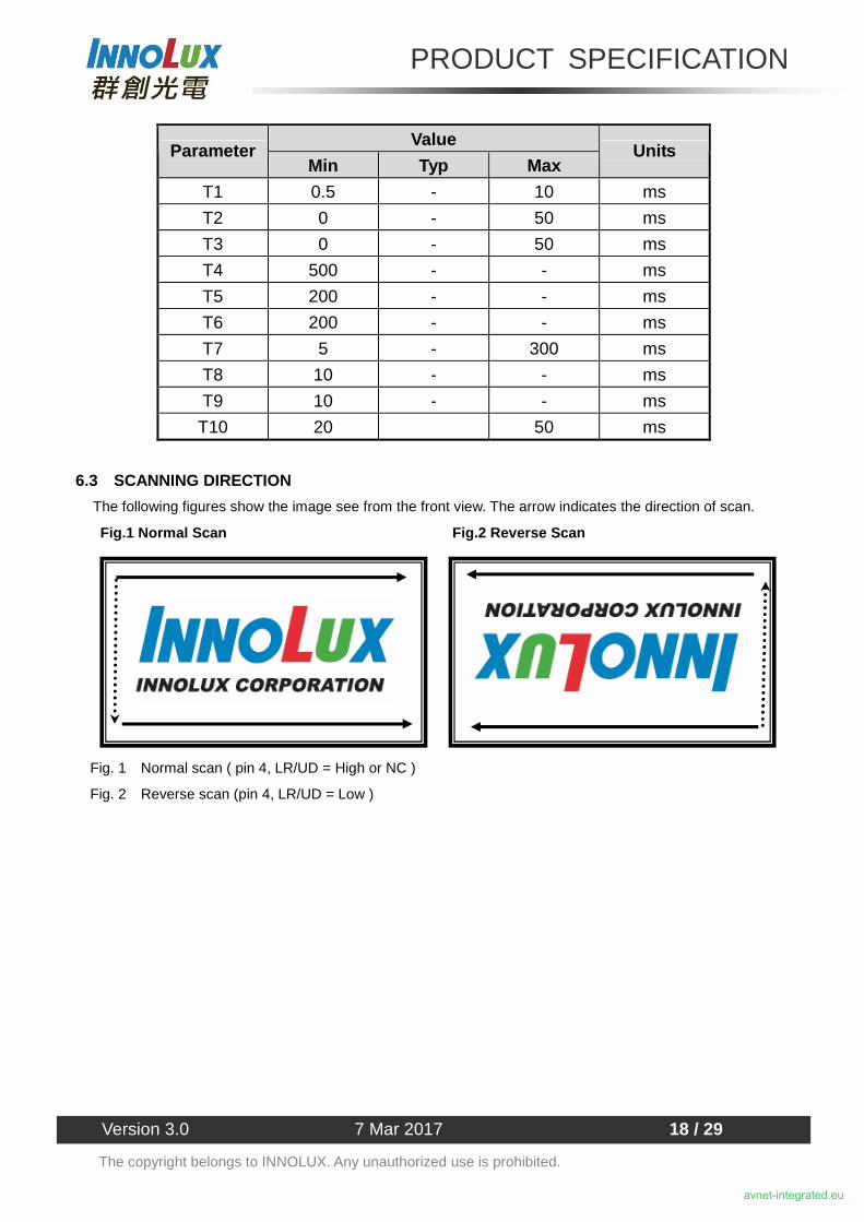
Pin No. Symbol Function Polarity Note 1 VCC Power Supply +3.3V(typical) 2 VCC Power Supply +3.3V(typical) 3 NC No Conncetion (Reserve for INX test) 4 LR/UD Reverse Scan Control
H or NC = Normal Mode. L = Horizonta/ Vertical Reverse Scan.
5 RX0- LVDS Differential Data Input Negative 6 RX0+ LVDS Differential Data Input Positive 7 GND Ground 8 RX1- LVDS Differential Data Input Negative 9 RX1+ LVDS Differential Data Input Positive 10 NC No Conncetion (Reserve for INX test) 11 RX2- LVDS Differential Data Input Negative 12 RX2+ LVDS Differential Data Input Positive 13 GND Ground 14 RXCLK- LVDS Differential Data Input Negative 15 RXCLK+ LVDS Differential Data Input Positive 16 GND Ground 17 RX3- LVDS Differential Data Input Negative 18 RX3+ LVDS Differential Data Input Positive 19 NC No Conncetion (Reserve for INX test) 20 SEL68 LVDS 6/8 bit select function control,
High � 6bit Input Mode Low or NC � 8bit Input Mode
Note (3)
Note (1) Connector Part No.: Cvilux CID520D1HR0-NH or equivalent.
Note (2) User’s connector Part No.: Hirose DF14-20S-1.25C or equivalent.
Note (3) “Low” stands for 0V. “High” stands for 3.3V. “NC” stands for “No Connection”.
avnet-integrated.eu
PRODUCT SPECIFICATION
Version 3.0 7 Mar 2017 13 / 29
The copyright belongs to INNOLUX. Any unauthorized use is prohibited.
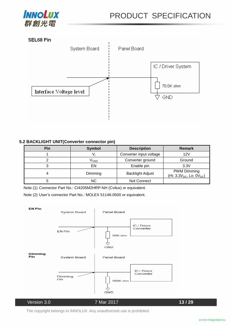
5.2 BACKLIGHT UNIT(Converter connector pin)
Pin Symbol Description Remark
1 Vi Converter input voltage 12V
2 VGND Converter ground Ground
3 EN Enable pin 3.3V
4 Dimming Backlight Adjust PWM Dimming
(Hi: 3.3VDC, Lo: 0VDC) 5 NC Not Connect
Note (1) Connector Part No.: CI4205M2HRP-NH (Cvilux) or equivalent.
Note (2) User’s connector Part No.: MOLEX 51146-0500 or equivalent.
avnet-integrated.eu
PRODUCT SPECIFICATION
Version 3.0 7 Mar 2017 14 / 29
The copyright belongs to INNOLUX. Any unauthorized use is prohibited.
5.3 COLOR DATA INPUT ASSIGNMENT
The brightness of each primary color (red, green and blue) is based on the 8-bit gray scale data input for
the color. The higher the binary input the brighter the color. The table below provides the assignment of
Shock (Non-Operating) 50G, 11ms, half sine wave, 1 time for ± X, ± Y, ± Z direction (2), (3)
Vibration (Non-Operating) 1.5G, 10 ~ 300 Hz sine wave, 10 min/cycle, 3 cycles each X, Y, Z direction
(2), (3)
Note (1) There should be no condensation on the surface of panel during test.
Note (2) Temperature of panel display surface area should be 90ºC Max.
Note (3) At testing Vibration and Shock, the fixture in holding the module has to be hard and rigid enough
so that the module would not be twisted or bent by the fixture.
Note (4) In the standard conditions, there is no function failure issue occurred. All the cosmetic specification
is judged before reliability test.
Note (5) Before cosmetic and function test, the product must have enough recovery time, at least 2 hours at
room temperature.
Note (6) Before cosmetic and function test, the product must have enough recovery time, at least 24 hours
at room temperature.
avnet-integrated.eu
PRODUCT SPECIFICATION
Version 3.0 7 Mar 2017 24 / 29
The copyright belongs to INNOLUX. Any unauthorized use is prohibited.
9. PACKAGING
9.1 PACKING SPECIFICATIONS
(1) 16pcs LCD modules / 1 Box
(2) Box dimensions: 511 (L) X 420 (W) X 360 (H) mm
(3) Weight: approximately 18Kg (16 modules per box)
9.2 PACKING METHOD
Figure. 9-1 Packing method
avnet-integrated.eu
PRODUCT SPECIFICATION
Version 3.0 7 Mar 2017 25 / 29
The copyright belongs to INNOLUX. Any unauthorized use is prohibited.
9.3 UN-PACKING METHOD
Figure. 9-2 Packing method
Figure. 9-3 UN-Packing method
avnet-integrated.eu
PRODUCT SPECIFICATION
Version 3.0 7 Mar 2017 26 / 29
The copyright belongs to INNOLUX. Any unauthorized use is prohibited.
10. DEFINITION OF LABELS
10.1 INX MODULE LABEL
The barcode nameplate is pasted on each module as illustration, and its definitions are as following explanation.
(a) Model Name: G150XNE -L01
(b) ﹡﹡﹡﹡: Factory ID
(c) Serial ID: X X X X X X X Y M D X N N N N
Serial ID includes the information as below:
(a) Manufactured Date: Year: 1~9, for 2011~2019
Month: 1~9, A~C, for Jan. ~ Dec.
Day: 1~9, A~Y, for 1st to 31st, exclude I , O and U
(b) Revision Code: cover all the change
(c) Serial No.: Manufacturing sequence of product
Year, Month, Date INX Internal Use Revision
Serial No.
INX Internal Use
INX Internal Use
X X X X X X X Y M D L N N N N
G150XNE -L01
﹡﹡﹡﹡ RoHS
E207943
avnet-integrated.eu
PRODUCT SPECIFICATION
Version 3.0 7 Mar 2017 27 / 29
The copyright belongs to INNOLUX. Any unauthorized use is prohibited.
11. PRECAUTIONS 11.1 ASSEMBLY AND HANDLING PRECAUTIONS
(1) Do not apply rough force such as bending or twisting to the module during assembly.
(2) To assemble or install module into user’s system can be only in clean working areas. The dust and oil
may cause electrical short or worsen the polarizer.
(3) It’s not permitted to have pressure or impulse on the module because the LCD panel and Backlight will
be damaged.
(4) Always follow the correct power sequence when LCD module is connecting and operating. This can
prevent damage to the CMOS LSI chips during latch-up.
(5) Do not pull the I/F connector in or out while the module is operating.
(6) Do not disassemble the module.
(7) Use a soft dry cloth without chemicals for cleaning, because the surface of polarizer is very soft and
easily scratched.
(8) It is dangerous that moisture come into or contacted the LCD module, because moisture may damage
LCD module when it is operating.
(9) High temperature or humidity may reduce the performance of module. Please store LCD module within
the specified storage conditions.
(10) When ambient temperature is lower than 10℃ may reduce the display quality. For example, the
response time will become slowly.
(11) Do not keep same pattern in a long period of time. It may cause image sticking on LCD.
11.2 SAFETY PRECAUTIONS
(1) Do not disassemble the module or insert anything into the Backlight unit.
(2) If the liquid crystal material leaks from the panel, it should be kept away from the eyes or mouth. In
case of contact with hands, skin or clothes, it has to be washed away thoroughly with soap.
(3) After the module’s end of life, it is not harmful in case of normal operation and storage.
avnet-integrated.eu
PRODUCT SPECIFICATION
Version 3.0 7 Mar 2017 28 / 29
The copyright belongs to INNOLUX. Any unauthorized use is prohibited.
12. MECHANICAL CHARACTERISTICS
avnet-integrated.eu
PRODUCT SPECIFICATION
Version 3.0 7 Mar 2017 29 / 29
The copyright belongs to INNOLUX. Any unauthorized use is prohibited.
avnet-integrated.eu
Offices
06/2017
All trademarks and logos are the property of their respective owners. This document provides a brief overview only, no binding offers are intended. No guarantee as to the accuracy or completeness of any information. All information is subject to change, modifications and amendments without notice.
FranceAvnet Integrated SolutionsAvnet EMG France SAParc Club du Moulin à Vent, Bât 1033, rue du Dr Georges Lévy 69693 Vénissieux CedexPhone: +33 4 78 77 13 92Fax: +33 4 78 77 13 [email protected]