FACTA UNIVERSITATIS Series: Mechanics, Automatic Control and Robotics Vol.3, N o 15, 2003, pp. 1055 - 1066 THE ANALYSIS OF CONTACT STRESS ON MESHED TEETH'S FLANKS ALONG THE PATH OF CONTACT FOR A TOOTH PAIR UDC 532.12+ 620.10+521.8 Vera Nikolić-Stanojević, Ivana (Atanasovska) Cvejić Faculty of Mechanical Engineering Kragujevac Sestre Janjić 6, 34 000 Kragujevac, Serbia Abstract. The basic task of this paper is analysing and determining the shape of the function which defines the change of contact stresses on tooth flanks along the path of contact for a tooth pair. The determination of contact stress maximum point and the calculation of its value is possible if the course of change of contact stress is provided. This enables the precise calculation of a gear pair pitting resistance. The numerical method – Finite Element Method (FEM) is used for modeling the contact of tooth flanks. This paper gives the detailed description of model development procedure. The results provided for the stress state of tooth flanks are also presented and discussed. The comparison of analyticly and numericly obtained curves of change in stress state on meshed tooth flanks, confirmed the accuracy of the developed model. This model opens new possibilities for succesful application in calculations and research involved in improving the geometry of gears pairs. Key words: Gears, Contact stress, The Finite Element Method INTRODUCTION Starting point in studying the contact strains on tooth flanks is to define the contact surfaces as the parts of equivalent imagined cylinders. The radii of these cylinders are identical to the radii of flanks' curvatures in contact point (ρ x ), [4]. During the contact period in unloaded state, the active surfaces of meshed teeth's flanks are in contact with each other through the instantaneous contact lines, which coincide with the common generatrix of involute surfaces. The forces of mutual action exist in teeth's mesh. They act in the direction of the common normal for contact surfaces, so they are known as normal load (F bn ). Received April 20, 2003
Transcript
FACTA UNIVERSITATISSeries: Mechanics, Automatic Control and Robotics Vol.3, No 15, 2003, pp. 1055 - 1066
THE ANALYSIS OF CONTACT STRESS ON MESHED TEETH'SFLANKS ALONG THE PATH OF CONTACT
FOR A TOOTH PAIR
UDC 532.12+ 620.10+521.8
Vera Nikolić-Stanojević, Ivana (Atanasovska) Cvejić
Faculty of Mechanical Engineering KragujevacSestre Janjić 6, 34 000 Kragujevac, Serbia
Abstract. The basic task of this paper is analysing and determining the shape of thefunction which defines the change of contact stresses on tooth flanks along the path ofcontact for a tooth pair. The determination of contact stress maximum point and thecalculation of its value is possible if the course of change of contact stress is provided.This enables the precise calculation of a gear pair pitting resistance.The numerical method – Finite Element Method (FEM) is used for modeling the contactof tooth flanks. This paper gives the detailed description of model developmentprocedure. The results provided for the stress state of tooth flanks are also presentedand discussed.The comparison of analyticly and numericly obtained curves of change in stress stateon meshed tooth flanks, confirmed the accuracy of the developed model. This modelopens new possibilities for succesful application in calculations and research involvedin improving the geometry of gears pairs.
Key words: Gears, Contact stress, The Finite Element Method
INTRODUCTION
Starting point in studying the contact strains on tooth flanks is to define the contactsurfaces as the parts of equivalent imagined cylinders. The radii of these cylinders areidentical to the radii of flanks' curvatures in contact point (ρx), [4]. During the contactperiod in unloaded state, the active surfaces of meshed teeth's flanks are in contact witheach other through the instantaneous contact lines, which coincide with the commongeneratrix of involute surfaces. The forces of mutual action exist in teeth's mesh. They actin the direction of the common normal for contact surfaces, so they are known as normalload (Fbn).
Received April 20, 2003
1056 V. NIKOLIĆ-STANOJEVIĆ, I. (ATANASOVSKA) CVEJIĆ
The action of normal load Fbn provokes elastic deformations on the contact surfacesof meshed teeth. Because of that, there is not flank contact through the contact line, butthrough the elastically deformed flank surfaces. In the case of involute spur gear, thecurvatures' radii of the meshed teeth are continuously changing during the meshingperiod, so the determination of contact stresses on meshed flanks is a task analogical withHertz's task for two cylinders in contact.
THE THEORETICAL ANALYSIS
The maximum local strain that appears on tooth flanks during the mesh period isrelevant for the calculation of gear's load capacity, according to tooth flanks' strengthcriterion. In order to determine the maximum strain value, one must, first of all,determine the nominal value of tooth flanks' loading and the corresponding load factors.Load factors take into consideration real working conditions and translate the nominalload value into the maximum load value. The maximum load is defined as maximumnormal load Fbn on tooth flanks, which is result of maximum tangential load, inaccordance with:
w
tβαVA
w
tmax
b2
2
b1
1bnbn2bn1 αcosαcos
22 FKKKKFdT
dTFFF ====== (1)
where: KA – is the application factor;KV – is the internal dynamic factor;Kα - is the factor of load distribution among simultaneously meshing tooth pairs;Kβ - is the factor of load distribution over the facewidth.
In the case of involutes spur gear, the curvatures' radii of the meshed teeth arecontinuously changing during the meshing period of a tooth pair, in accordance withfollowing expression:
xxxbx sinαtgαρ ⋅=⋅= rr (2)
When the expressions that correspond for tooth flanks' contact:
bFq bn= ;
21
21
ρρρρ
λ21ρ
+⋅== and 211
i
2i
i ,i,E
k =ν−= (3)
are inserted in Hertz's solution for two cylinders in contact, [5]:
21
λπ2
π2
kkq
aqpmax +
⋅⋅=⋅
= (4)
then it takes a form applicable for the calculation of the maximum Hertzian contactstresses in the points of mesh without slipping for single tooth pair meshing period:
−+−⋅π
⋅⋅
=σ
2
22
1
21
bnH
ν1ν11
ρ
EEbF (5)
The Analysis of Contact Stress on Meshed Teeth's Flanks along the Path Contact for a Tooth Pair 1057
where: ρ is the equivalent curvature's radius in a contact point.
With application of the expression for the radii of flanks' curvatures and theexpression for the equivalent curvature's radius in the contact point, the expression (5)takes a form applicable for the active stress calculation while the contact is in the pitchpoint C (σH0):
w2
1
max
2
22
1
21
0H αtgαcos21
ν1ν1π
1σ⋅
⋅+⋅⋅
⋅
−+−⋅
=u
udb
F
EE
t (6)
It is possible to monitor the change of active stress on tooth flanks through the changeof ratio of active stress in any contact point σHx and active stress for contact in the pitchpoint σH0. If the equations for the calculation of the active stresses on meshing toothflanks, which are developed from the Hertz's solution for contact stresses while twocylinders are in contact, are applied, then this ratio takes the following form:
)cos()()cos()(
Ctmax
xtmax
0 wC
wx
H
Hx
b/Fb/F
α⋅ρ⋅α⋅ρ⋅
=σσ (7)
where: ρx and ρC – are the equivalent curvature's radii in any contact point and the pitch
point, in accordance with: 21
21
ρρρρ
λ21ρ
+⋅== ;
tαβxVAxtmax )( FKKKKF x ⋅⋅⋅⋅= – is the maximum tangential load for contact in anypoint on the path of contact;
tαVACtmax )( FKKKKF CC ⋅⋅⋅⋅= β – is the maximum tangential load for contact in thepitch point.
If n tooth pairs are simultaneously meshed and Fi is the load transferred by ith toothpair, then the factor of load distribution among simultaneously meshing tooth pairs for ith
tooth pair (Kαi) describes the level of interest in mesh for ith tooth pair. It is defined withthe following quotient:
FFK i
αi = , ∑=
=n
iFF
1i (8)
In accordance with the assumption that tangential force per unit tooth width isconstant during the meshing period (Kβ=const.), the ratio (7) takes a form suitable formonitoring the changes of contact stress on tooth flanks during the contact period for atooth pair:
αC
αxρx
H0
Hx
KKZ ⋅=
σσ (9)
where:Kαx and KαC – are factors of load distribution among simultaneously meshing toothpairs for contact in any point and in the pitch point; xCx /Z ρρ=ρ – is radius factor forcurvatures of meshed teeth's profiles for contact in any point on the line of contact.
1058 V. NIKOLIĆ-STANOJEVIĆ, I. (ATANASOVSKA) CVEJIĆ
During the meshing period for a tooth pair of a gear pair, the factor of loaddistribution among simultaneously meshing tooth pairs Kα is defined as the function ofthe loading value, the tooth stiffness and the difference between meshing teeth's basepitches. In meshing periods for two simultaneously meshing tooth pairs, factor Kα ischanging in accordance with the complex continuous functions. However, the knowledgeof these functions is not important. For the calculation of tooth flanks strength, theimportant information is only maximum loads in the moments of load exchange amongtooth pairs in mesh. Consequently, these functions can be assumed as linear functions.
In this paper, for the theoretically and numerically analyses, one particular gear pairfor large transport machines (dradges) are taken. Its characteristics are given in tab.1.The results of theoretically analysis of the changes of active stress on meshed toothflanks, obtained through the computer program developed in [1], are given in figure 1.The curve in figure 1 is obtained for ideally manufactured (∆pb=0) gear pair and inaccordance with the described assumptions.
Table. 1.
Quantity Symbol Valuez1 20Number of teeth z2 96x1 0Addendum modification
coefficient x2 0,328Facewidth b 350 mmModule m=mn 24Pressure angle α=αn 20°Helix angle β 0°Rotational speed of wheel n2 4,1596 min-1
T1 526,41667 KN⋅mPinion torque and wheel torque T2 2526,8 KN⋅mUseful level η 1
Fig. 1. Active stress on tooth flanks for the studied gear pair, while ∆pb=0
A B D E
x/pb
σHx/σH0
The Analysis of Contact Stress on Meshed Teeth's Flanks along the Path Contact for a Tooth Pair 1059
THE FINITE ELEMENT METHOD AND PLANE CONTACT PROBLEMS
In accordance with the described procedure for calculation of stresses on tooth flanks,it can be concluded that the solving of the defined task by the analytical methods is verycomplex and possible only with many assumptions. So, for this problem, as well as foralmost all problems in Theory of elasticity, the numerical methods must be used. Insteadof a system of differential (simple, partial and integral) equations, which are defined forsolving some problem in Theory of elasticity, numerical methods form correspondingsystem of simple algebraic equations. By using computers, that system can be solvedquickly and successfully. So, for studying the problem of contact stresses on tooth flanks,the Finite Element Method (FEM) is chosen. The Finite Element Method formulates thedifferential equations of balance of an elastic body. By taking into consideration theboundary conditions, the number of unknown quantities in these equations becomessmaller.
The Finite Element Method is based on the principles of the mechanics of continuum.The mechanical values, which are used in mechanics of continuum, are continuousfunctions of points' coordinates, so they are differentiable in accordance to coordinates.Material point of continuum presents an infinitely small particle of continuously disposedmaterial, and its position is defined by geometrical point of space.
When variational principles, i.e. energy principles, are applied, variational equationstake the form of integral equations. The variational principle of the maximum potentialenergy is the most frequently used principle in the Finite Element Method and it isdescribed in [2], [3], [7].
Primary task in studying a deformable body by the FEM, is to choose a discretemodel, which gives the most proper approximations for stress state, strain state andboundary conditions. The discreted model of continuum is obtained by its division onfinite elements. Finite elements are mutually joined with common nodes. For modelingthe whole construction, one can simultaneously use either the finite elements of only onetype or the finite elements of a few different types. The basic differences among the finiteelements of different types are differences in their shapes and interpolation functions. Thespecial finite element types, which are used in solving engineering problems, are: theisoparametric finite elements (which use the same interpolation functions for theapproximation of element geometry and for the approximation of basic unknownquantities in the field of a finite element) and the subparametric finite elements (thenumber of nodes for the approximation of element geometry is bigger than the number ofnodes for the approximation of other functions).
The choice of an optimum discreted model for exact and economical calculation isdirectly dependent on the engineering experience and the knowledge about thecharacteristics of stress and deformation states for the studied construction. Basically, thediscreted model selection is based on two major tasks: the selection of finite element typeand the selection of necessary mesh density.
The method of deformation is used for modeling the contact problem. It is the mostfrequently used method in the FEM, and its basic task is to determine the functions ofdisplacement. The displacements of any point of a finite element can be determined asthe functions of displacement values for mesh nodes. It adopts that displacements,deformations and stresses are the continuous functions of coordinates of a finite element'spoints.
1060 V. NIKOLIĆ-STANOJEVIĆ, I. (ATANASOVSKA) CVEJIĆ
The finite element's equation, if the influence of temperature strains is ignored, givesthe connection between the node displacements and node forces:
}]{[}{ SKF e= (11)
where: {F} − is a vector of external node forces for a finite element;{S} − is a vector of node desplacement for a finite element and[Ke] − is a stiffness matrix for a finite element.
The elements of these vectors and matrix depend on physical material characteristics,characteristics of chosen finite element type and choosed interpolating functions.
The construction equation is obtained by combining the equations for all finiteelements that make the mesh of a body or a construction:
}]{[}{ SKF = (12)where:
=
}{
}{
}{
}{
)(
)2(
)1(
nF
F
F
F!
;
=
}{
}{
}{
}{
)(
)2(
)1(
nS
S
S
S!
(13)
In these vectors, n is the total node number, which is equal to the sum of the totalnode number in finite element mesh and the number of construction support. Every termof the vectors (13) is a vector with the number of elements equal to the number ofdegrees of freedom for finite element's nodes. Therefore, both of the vectors{ F} and { S}have p×n elements (p – number of the degrees of freedom, n – number of nodes), and thestiffness matrix [K] has nxn submatrices rsK .
Some node displacements are known in advance. They are defined by constructionsupport and present the boundary conditions. When they are included in the constructionequation, some equations become eliminated. Thereby, the total number of the degrees offreedom becomes smaller. The Finite Element Method takes into consideration theexternal forces (which come into action in some mesh nodes and present the loading of aconstruction) by including the force components, in the directions of coordinate axis, inthe construction equation. If a construction is loaded with concentrated forces, there is amesh node in each point struck by concentrated force's action. If a construction is loadedwith continuously distributed load, this load is replaced with equivalent node forces. Inthat case, the knowledge of unit load along the line or along the loading surface isrequired.
The FEM treats a plane contact problem as a part of the general problem of bodies'movement in space and their interaction. The problem of this type ca be described by twobodies that get in contact because of the action of external forces. One of these bodies isdefined as a contactor body, and the other as a target body. The procedure of choosing acontact body is simple when the Finite Element Method examines a stiff body and adeformable body in contact. But in the case of two deformable bodies in contact, the
The Analysis of Contact Stress on Meshed Teeth's Flanks along the Path Contact for a Tooth Pair 1061
FEM procedure is complex and requires excellent knowledge of the character of contactwhich is to be analysed. When the bodies are in contact, contact forces appear. Theseforces prevent mutual penetration of bodies and provoke deformations in contact areas.For the calculation of contact problems (nonlinear numerical problems) the FiniteElement Method most frequently uses the Method of Lagrange multipliers.The simplest FEM procedure for modeling contact conditions, is the one that uses finiteelements in the form of nonlinear sticks with the assigned characteristic of pressurecapacity and without stiffness in the case of tension ("gap" elements). Only the finiteelements, for which exists the possibility that they will be in contact, are defined as thecontact elements. These elements consist of nodes and lines that are located on theborders of bodies. In order to reduce the calculating time, only the part of the border thatwill possibly be in contact with the contactor body is defined as the contact surface of thetarget body. A contact element is defined as a connection between a node of a contactorbody (contactor node) and a target segment of a target body.During the calculation, the FEM procedure finds the nodes of the target surfaces and thecorresponding contactor nodes that together make "the instantaneous contact elements".For each instantaneous contact element, the FEM procedure forms the stiffness matrix,the vector of displacement and the vector of internal forces in accordance with theanalysis of the variation of contact forces potential. These matrices and vectors presentthe influence of an instantaneous contact finite element on the system, which consists ofmatrices for all finite elements of contact bodies (structural finite elements and contactfinite elements).
THE FEM MODEL DEVELOPED FOR TOOTH FLANKS IN CONTACT
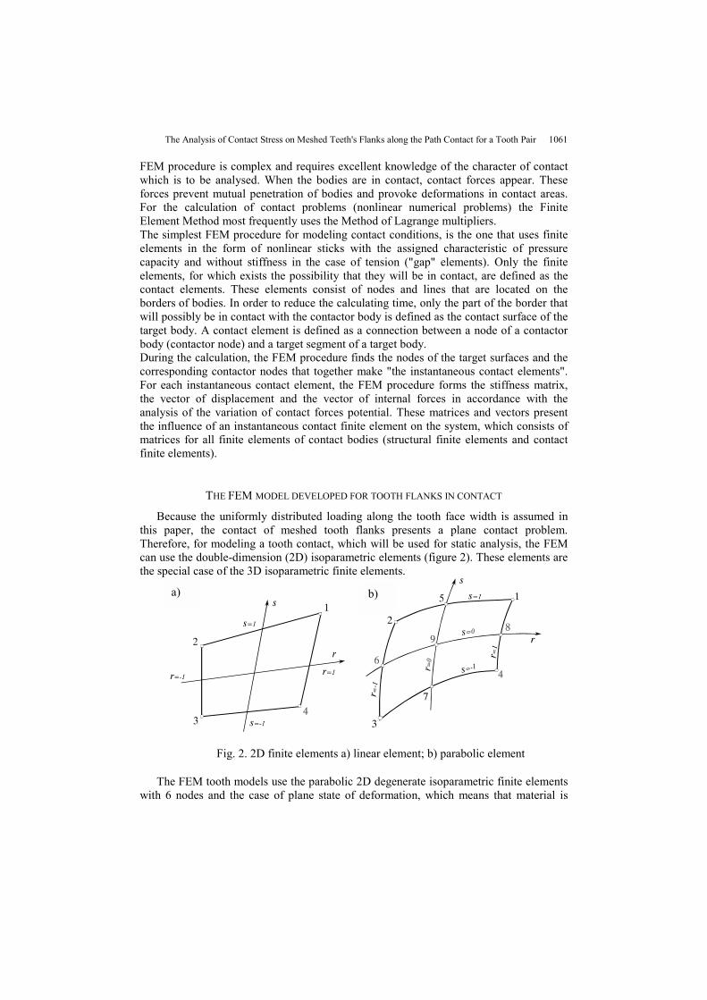
Because the uniformly distributed loading along the tooth face width is assumed inthis paper, the contact of meshed tooth flanks presents a plane contact problem.Therefore, for modeling a tooth contact, which will be used for static analysis, the FEMcan use the double-dimension (2D) isoparametric elements (figure 2). These elements arethe special case of the 3D isoparametric finite elements.
Fig. 2. 2D finite elements a) linear element; b) parabolic element
The FEM tooth models use the parabolic 2D degenerate isoparametric finite elementswith 6 nodes and the case of plane state of deformation, which means that material is
a) b)
1062 V. NIKOLIĆ-STANOJEVIĆ, I. (ATANASOVSKA) CVEJIĆ
identically deforming in all planes parallel with x,y plane. The degenerate element, shownin figure 3, is obtained by overlapping of two corner nodes (1 and 4), so that thecorrection of the interpolation functions b1 appears. Then, the function is equal to the sumof the interpolation functions for nodes 1 and 4:
)1(21
411 rbbb* +=+= (14)
The same procedure is used for the degeneration of the parabolic 2D elements.Triangular 2D isoparametric element with 6 nodes is obtained by the degeneration of 2Delement with 8 nodes.
Fig. 3. The degeneration of 2D element
The tooth contact models are developed for the gear pair with characteristics given intable 1. Each of these models consists of three groups of elements: the group of elementsthat define the tooth of the pinion, the group of elements that define the tooth of thewheel and the group of contact elements. This paper's goal is to investigate the change ofcontact stress on meshed teeth, along the path of contact, so the most important thing isthe determination of contact stress states for the contacts in characteristics points on thetooth profile (A, B, C, D and E). A computer program developed in [1] provides the radiithat correspond to these points. For contact in each characteristic point, the special modelin the FEM was made, so that the global coordinate system remained unchanged. That isespecially suitable for monitoring the results.
Boundary conditions are defined as the limits of all translational and rotationaldisplacements for those contour nodes in tooth models that present the connections withthe gear body. A few concentrated forces along the external involute surfaces of meshedteeth simulate the loading, so that the total momentum that is loading the tooth mesh isequal to the momentum on the gear shaft. This choice for load simulation is the result ofthe investigation of different load simulations on the model of a tooth pair. The selectedload simulation yields the distribution of stress and deformation state in the tooth contact,most similar to the distribution obtained from the experimental data acquired by theexperimental photoelastic method, [3].
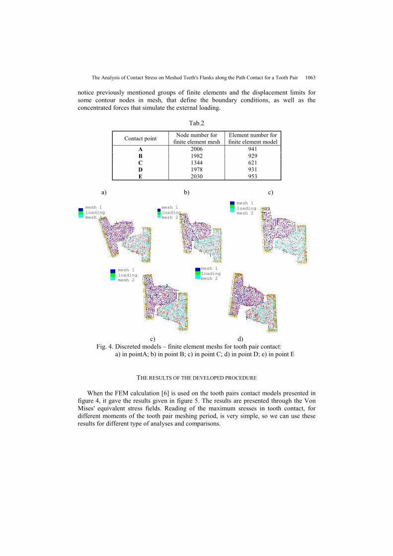
Tab.2 gives the view of node numbers and element numbers for the developed modelsand figure 4 presents discreted FEM models for all characteristic contact points (firstcontact point – A, point of passing from period with two tooth pairs in contact to singlemeshed tooth pair period – B, pitch point – C, point of passing from single meshed toothpair period to period with two pairs in contact – D, last contact point – E). It is easy to
The Analysis of Contact Stress on Meshed Teeth's Flanks along the Path Contact for a Tooth Pair 1063
notice previously mentioned groups of finite elements and the displacement limits forsome contour nodes in mesh, that define the boundary conditions, as well as theconcentrated forces that simulate the external loading.
c) d)Fig. 4. Discreted models – finite element meshs for tooth pair contact:
a) in pointA; b) in point B; c) in point C; d) in point D; e) in point E
THE RESULTS OF THE DEVELOPED PROCEDURE
When the FEM calculation [6] is used on the tooth pairs contact models presented infigure 4, it gave the results given in figure 5. The results are presented through the VonMises' equivalent stress fields. Reading of the maximum sresses in tooth contact, fordifferent moments of the tooth pair meshing period, is very simple, so we can use theseresults for different type of analyses and comparisons.
mesh 1loadingmesh 2
mesh 1loadingmesh 2
mesh 1loadingmesh 2
mesh 1loadingmesh 2
mesh 1loadingmesh 2
1064 V. NIKOLIĆ-STANOJEVIĆ, I. (ATANASOVSKA) CVEJIĆ
a) b)
b) c)
e)
Fig. 6. Von Mises' equivalent stress fields for the tooth pair contact:a) in pointA; b) in point B for the single meshed tooth pair period; c) in point C;d) in point D for the single meshed tooth pair period; e) in point E
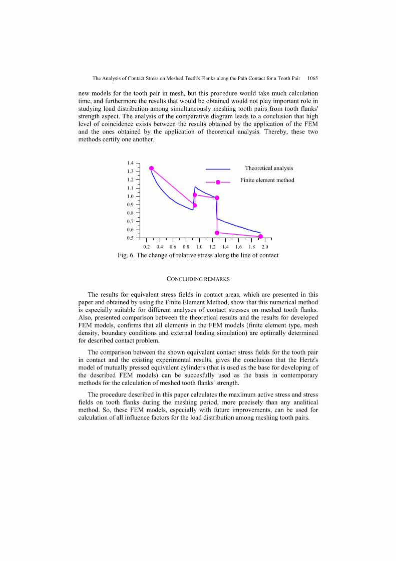
The model developed and described in this paper corresponds to an ideal gear, sothese numerical results can be compared with the theoretical results shown in figure 1.Figure 6 presents a comparative diagram for the change of relative contact stress alongthe line of contact for a tooth pair in mesh. This diagram is a result of the theoreticalanalysis and the FEM calculation models given in figure 4. Because there are no resultsthat correspond to every contact point on the line of contact, straight lines occur in thediagram obtained by the FEM calculation. Other results can be obtained by developing
Von Mises (N/cm*2)
2.10E+051.84E+051.57E+051.31E+051.05E+057.87E+04
5.25E+042.62E+04
0.002080
Von Mises (N/cm*2) 1.60E+051.40E+051.20E+059.99E+04
8.01E+046.00E+043.99E+042.01E+040.012040
STRESS Step:10 =1STRESS Step:10 =1
1.57E+051.37E+05
1.18E+059.81E+04
7.85E+04
5.88E+043.92E+041.96E+040.001100
Von Mises (N/cm*2)
STRESS Step:10 =1
1.54E+051.34E+051.15E+05
9.61E+04
7.68E+045.76E+043.85E+041.92E+04
0.001300
Von Mises (N/cm*2)
STRESS Step:10 =1
8.13E+04
7.11E+04
6.09E+04
5.08E+04
3.04E+042.02E+041.01E+040.000580
STRESS Step:10 =1
Von Mises (N/cm*2)
The Analysis of Contact Stress on Meshed Teeth's Flanks along the Path Contact for a Tooth Pair 1065
new models for the tooth pair in mesh, but this procedure would take much calculationtime, and furthermore the results that would be obtained would not play important role instudying load distribution among simultaneously meshing tooth pairs from tooth flanks'strength aspect. The analysis of the comparative diagram leads to a conclusion that highlevel of coincidence exists between the results obtained by the application of the FEMand the ones obtained by the application of theoretical analysis. Thereby, these twomethods certify one another.
0.2 0.4 0.6 0.8 1.0 1.2 1.4 1.6 1.8 2.0
0.5
0.6
0.7
0.8
0.9
1.01.1
1.2
1.3
1.4
Fig. 6. The change of relative stress along the line of contact
CONCLUDING REMARKS
The results for equivalent stress fields in contact areas, which are presented in thispaper and obtained by using the Finite Element Method, show that this numerical methodis especially suitable for different analyses of contact stresses on meshed tooth flanks.Also, presented comparison between the theoretical results and the results for developedFEM models, confirms that all elements in the FEM models (finite element type, meshdensity, boundary conditions and external loading simulation) are optimally determinedfor described contact problem.
The comparison between the shown equivalent contact stress fields for the tooth pairin contact and the existing experimental results, gives the conclusion that the Hertz'smodel of mutually pressed equivalent cylinders (that is used as the base for developing ofthe described FEM models) can be succesfully used as the basis in contemporarymethods for the calculation of meshed tooth flanks' strength.
The procedure described in this paper calculates the maximum active stress and stressfields on tooth flanks during the meshing period, more precisely than any analiticalmethod. So, these FEM models, especially with future improvements, can be used forcalculation of all influence factors for the load distribution among meshing tooth pairs.
Theoretical analysis
Finite element method
1066 V. NIKOLIĆ-STANOJEVIĆ, I. (ATANASOVSKA) CVEJIĆ
REFERENCES
1. Atanasovska I.: "Analiza raspodele opterećenja na spregnute parove zubaca sa osvrtom na čvrstoću bokazupca zupčanika", Magistarska teza, Kragujevac, 1999.
2. V. Nikolić: Mehanička analiza elemenata zupčastih prenosnika, monografija, Mašinski fakultet uKragujevcu, 1999.
3. Kojić M., Slavković R., Živković M., Grujović N.: "Metod konačnih elemenata I, linearna analiza",monografija, Univerzitet u Kragujevcu, Mašinski fakultet, Kragujevac, 1998.
4. V. Nikolić: "Mašinski elementi, teorija i primeri", Kragujevac, 1995. 5. Lorenz H.: "Verbesserte Zahnfuβfestigkeit", Dortmund. 6. Rašković D.: "Teorija elastičnosti", Naučna knjiga, Beograd, 1985. 7. Hedrih (Stevanović) Katica, ''Izabrana poglavlja teorije elastičnosti'', Niš, 1988. 8. Software COSMOS Mexplorer, version 1-7 from SRAC. 9. V. Nikolić: ''Istraživanje naponskog i deformacionog stanja glavnih strukturnih elemenata zupčastih
prenosnika velikih snaga primenom metode konačnih elemenata'', doktorska disertacija, 1989, Niš. 10. V. Nikolić: "Stress - state investigation of heavy loaded gear drives", MVM- nternational Journal for
Vehicle Mechanics, Engines and Transportation Systems,Volume 19, Number 3, Septembar, 1993. str.25...32.
11. V. Nikolić: "Analysis of the stress state of gear drive using numerical method'', International Journal forVehicle Mechanics, Engines and Transportation Systems, Volume 20, Number 4, December, 1994, str.33... 39.
12. V. Nikolić, D. Dimitrijević: "On application of numerical methods in the studies of toothed gears",International Symposium "Machines and Mechanisms", Belgrade, September, 2-5. 1997.
ANALIZA KONTAKTNIH NAPONA NA MREŽI ZUBADUŽ KONTAKTA ZA PAR SPREGNUTIH ZUBA
Vera Nikolić- Stanojević, Ivana (Atanasovska) Cvejić
Osnovni zadatak u ovom radu je analiza i odredjivanje oblika funkcije koja definiše promenukontaktnih napona na ivici-boku zuba duž puta kontakta za par zuba. Odredjivanje tačkemaksimalnog napona kontakta i njihov proračun je moguć ako je pravac kontakta zuba predvidljiv.Korišćena je numerička metoda – metoda konačnih elemenata za modeliranje kontakta zuba. Ovajrad daje detaljan opis razvoja procedure. Uporedjeni su analitički i numerički rezultati.