+ All Categories
Home > Documents > The Analysis of Open Web Steel Joists in Existing Buildings · Source: Vulcraft Because of the...

The Analysis of Open Web Steel Joists in Existing Buildings · Source: Vulcraft Because of the...

Date post: 30-Jul-2018
Category:
Upload: nguyenkiet
View: 217 times
Download: 0 times
Share this document with a friend
13
PDHonline Course S117 (1 PDH) The Analysis of Open Web Steel Joists in Existing Buildings Instructor: D. Matthew Stuart, P.E., S.E., F.ASCE, F.SEI, SECB, MgtEng 2013 PDH Online | PDH Center 5272 Meadow Estates Drive Fairfax, VA 22030-6658 Phone & Fax: 703-988-0088 www.PDHonline.org www.PDHcenter.com An Approved Continuing Education Provider
Transcript

PDHonline Course S117 (1 PDH)

The Analysis of Open Web Steel Joists

in Existing Buildings

Instructor: D. Matthew Stuart, P.E., S.E., F.ASCE, F.SEI, SECB, MgtEng

2013

PDH Online | PDH Center

5272 Meadow Estates Drive Fairfax, VA 22030-6658

Phone & Fax: 703-988-0088 www.PDHonline.org www.PDHcenter.com

An Approved Continuing Education Provider

www.PDHcenter.com www.PDHonline.org

©D. Matthew Stuart

1

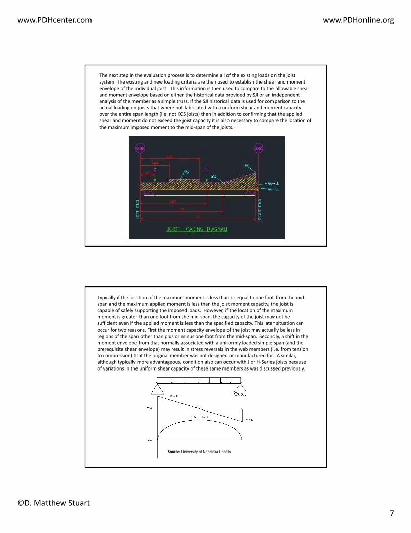
Fabricated open web joists are manufactured in this country by a number of different companies. Open web joists are designed and fabricated per the Steel Joist Institute (SJI) specifications. However, at one time there was enough variation in the design and fabrication of these types of structural members that the allowable load tables published by SJI actually represented the approximate average load carrying capacity of any given member manufactured in the industry. A comparison of some of the older SJI load tables to the allowable load tables published by any individual producer at the same time will highlight this fact. It is also important to note that because open web joists are really proprietary fabricated trusses these members do not lend themselves well to in-situ strengthening or reinforcing when compared to standard rolled steel sections. Therefore a structural engineer is often faced with a daunting task when evaluating an existing structure constructed with joists and joist girders.

Source: Vulcraft

Because of the reasons indicated in the previous slide it is not recommended that the engineer-

of-record for the retrofit of a building assume the responsibility for the design of the

strengthening of the existing joists and joist girders. The only exception to this situation should be

when supplemental web members are added when loads occur between panel points and it is

necessary to transfer the reaction to the closest adjacent panel point at the opposing chord.

www.PDHcenter.com www.PDHonline.org

©D. Matthew Stuart

2

The reason for this position is as follows. Although it is possible to analyze individual component members of joists or joist girders for increased loads, it is very difficult if not impossible to document the capacity of existing welds at the panel points. Although bottom chord panel point welds can usually be documented in the field fairly easily, this task can still be a considerable undertaking. In addition, more often than not the welds at the top chord panel points are not accessible because of the interference from roof or floor decking. In fact, in situations where the manufacturer of a particular joist is known, unless the same producer has enough information archived on the particular project members, the manufacturer’s engineer can only assume that their minimum standard weld was provided. If this minimum information is available the manufacturer can develop strengthening details for the joists, however, the reinforcing is typically conservative because of the assumptions made by the manufacturer.

Source: Electronic Library of Construction Occupational Safety & Health

In either case, if the manufacturer of the joist

cannot be located or contacted but the type of

the joist and individual member sizes can be

established, it is still recommended that the

engineer-of-record should not design

strengthening measurers for the joists. To assist

the engineer through the process of reviewing

existing joists and determining the options

available to safely support new loads the

following flowchart can be used.

www.PDHcenter.com www.PDHonline.org

©D. Matthew Stuart

3

When analyzing older structures, it is

common to come across members that are

no longer produced. It is often difficult to

locate allowable load tables for these

members. An excellent publication is

available however from SJI for determining

the load carrying capacity of older

members. Even though this slide shows a

copy of the 60-Year manual, the title of the

latest reference book is the SJI 75-Year

Manual, which covers most joists and joist

girders manufactured between 1928 and

2005.

Source: Steel Joist Institute

It is also helpful when reviewing the allowable load tables for older joists to have an understanding

of how to properly interpret the tables. To provide an example of how to interpret an older load

table, a partial copy of SJI’s allowable joist load table (circa. 1961) for a H-Series joist is provided on

this slide.

www.PDHcenter.com www.PDHonline.org

©D. Matthew Stuart

4

Assume an existing 18H5 joist spanning 30'. The SJI allowable joist load table indicates that the

Maximum Allowable End Reaction for this joist is 4,500 LBS, which is significantly higher than

3615 LBS allowable shear capacity derived from the formula wL/2 (based upon an allowable

uniform load of 241 PLF for a 30' 18H5 joist span).

These differences in shear capacities result from the following. On the allowable load tables, each

joist column has a horizontal blue line separating where the allowable uniform loading of the

joists is controlled by the shear capacity of the joist and where the allowable uniform loading of

the joist is controlled by the moment capacity. The allowable shear for an H-Series joist starts at

the Maximum End Reaction value (given in the table) and decreases by the allowable uniform

load value given just above the blue transition line until it reaches a minimum value of 1/2 of the

maximum end reaction. For this example, the allowable joist shear starts at 4,500 LBS at each end

of the joist and decreases by 375 pounds per foot (the allowable uniform load value just above

blue line for a 18H5) until it reaches a value of 2,250 LBS (1/2 of 4,500 LBS) at which point the

slope of the allowable shear line is flat.

The following graphs show the comparison of the allowable shear of the 18H5 joist example

based upon both a wL/2 calculation and the more accurate method described in the previous

slide. As you can see, this later method gives higher values for allowable shear at every location

on the joist.

www.PDHcenter.com www.PDHonline.org

©D. Matthew Stuart

5

The evaluation and strengthening of existing

open web steel joists and joist girders is often

required as a result of equipment upgrades or

new installations, and adaptive reuse or

change in use of a facility. The SJI provides an

excellent resource for the evaluation and

modification of existing joists and joist girders

in Technical Digest No. #12.

Source: Steel Joist Institute

The first step in the process of evaluating an existing joist is to determine the capacity of the

member. Ideally, the best method of determining the member capacity is through the original

construction or shop drawings, which allow the identity of the joist to be established. Similarly, it

is also sometimes possible to identify the joist via fabrication tags left attached to the joists in the

field. However, if tags can be found, more often than not the tag only identifies the shop piece

mark number rather than the actual joist designation.

Source: Precision CADD & Graphics

www.PDHcenter.com www.PDHonline.org

©D. Matthew Stuart

6

In some instances, it may only be possible to

establish the type or series of the joist through

the available documentation. In this situation

it is possible to conservatively assume that the

capacity of the existing joist is no more than

the lightest joist in the series for the given

depth. In addition, if it is not clear whether a J

or an H-Series joist is involved, the J-Series

joist should always be conservatively assumed

because of its lower load carrying capacity.

However, if a definitive distinction is required,

and it is possible to secure a material sample

in order to obtain results from a standard

ASTM tension coupon test, a determination as

to whether the joist is 36 ksi (J- Series) or 50

ksi (H-Series) can be made.

Source: Steel Joist Institute

Joist Investigation Form: http://www.steeljoist.org/investigation

• Engineers, Architects, Specifying Professionals, Contractors, and others trying to identify older joists found in the field can

now fill out the form below, or they can use this downloadable form to provide the necessary information to the SJI office.

Please fill out as much information as possible. This will help the SJI office in making a proper match of your joist information

to those in our extensive historical files.

• When filling in the form regarding the joist chord and web member properties, it is recommended that the field

measurements be taken with a micrometer rather than a tape measure, since chord thicknesses can vary by as little as 1/64

inch and web diameters can vary by 1/32 inch.

• Sending pictures or sketches of the joist profiles is also recommended when the member cross-sections seem to be of a

proprietary nature. When you submit the form below and want to submit photographs or sketches to go along with it, please

email them to [email protected]

If no drawings are available it is still possible to establish the approximate capacity of the member by

field measuring the chord and web member sizes as well as the overall configuration of joist. This

information can then be used to analyze the structure as a simple truss. Critical assumptions that must

be made with this approach include; the yield strength of the members, and if the existing panel point

welds are capable of developing the full capacity of the connected component members. An

alternate method to the above approach includes filling out the Joist Information Form located on the

SJI website. SJI has indicated that they have been very successful in identifying the series and

designation for many older joists with this resource.

www.PDHcenter.com www.PDHonline.org

©D. Matthew Stuart

7

The next step in the evaluation process is to determine all of the existing loads on the joist

system. The existing and new loading criteria are then used to establish the shear and moment

envelope of the individual joist. This information is then used to compare to the allowable shear

and moment envelope based on either the historical data provided by SJI or an independent

analysis of the member as a simple truss. If the SJI historical data is used for comparison to the

actual loading on joists that where not fabricated with a uniform shear and moment capacity

over the entire span length (i.e. not KCS joists) then in addition to confirming that the applied

shear and moment do not exceed the joist capacity it is also necessary to compare the location of

the maximum imposed moment to the mid-span of the joists.

Typically if the location of the maximum moment is less than or equal to one foot from the mid-

span and the maximum applied moment is less than the joist moment capacity, the joist is

capable of safely supporting the imposed loads. However, if the location of the maximum

moment is greater than one foot from the mid-span, the capacity of the joist may not be

sufficient even if the applied moment is less than the specified capacity. This later situation can

occur for two reasons. First the moment capacity envelope of the joist may actually be less in

regions of the span other than plus or minus one foot from the mid-span. Secondly, a shift in the

moment envelope from that normally associated with a uniformly loaded simple span (and the

prerequisite shear envelope) may result in stress reversals in the web members (i.e. from tension

to compression) that the original member was not designed or manufactured for. A similar,

although typically more advantageous, condition also can occur with J or H-Series joists because

of variations in the uniform shear capacity of these same members as was discussed previously.

Source: University of Nebraska Lincoln

www.PDHcenter.com www.PDHonline.org

©D. Matthew Stuart

8

In situations in which it has been confirmed that the existing joists do not have sufficient capacity

to support the new loads; there are three methods that can be used to rectify the condition:

1. Load Redistribution.

2. Adding new joists or beams.

3. Reinforcing existing joists.

Load redistribution involves the installation of a sufficiently stiff member perpendicular to the

span of the joist as required to distribute the applied load to enough adjacent joists such that no

one joist is overstressed as a result of the new loading. Adding new joists or beams typically

involves the installation of a new framing member parallel to the joist span such that all or most

of the new applied load is supported by the new framing. New self-supporting beams can also be

installed perpendicular to the joist span as required to reduce the original span length of the

member. Finally, new independent, self-supporting beam and column frames can also be installed

to circumvent the imposition of any new loads on the existing joist framing system. Reinforcing

involves the installation of supplemental material to the original joist as required to increase the

load carrying capacity of the member.

Example of Bottom Chord Reinforcement

www.PDHcenter.com www.PDHonline.org

©D. Matthew Stuart

9

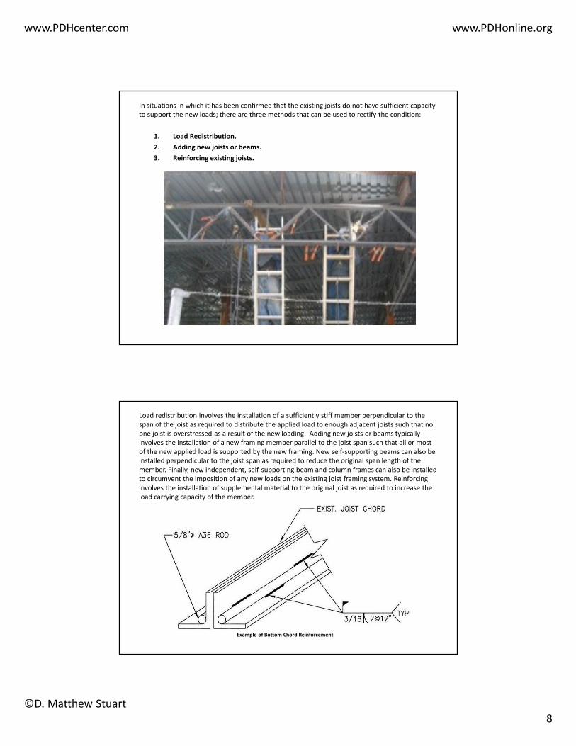
The key to the successful use of load redistribution involves the installation of a structural member that can adequately and predictably distribute the applied load to enough adjacent joists to justify the safe support of the load. A method of calculating the relative stiffness of a distribution member is available in in “Designing With Steel Joists, Joist Girders, Steel Deck” by Fisher, West & Van De Pas and is illustrated below:

β = ((�

�)/(4��)

Where: K = Stiffness of the joist, kips/inch

S = Spacing of the joists

E = Modulus of Elasticity of beam

I = Moment of Inertia of beam

If S < π/4β the beam on elastic support calculations are applicable. If the spacing limit is not exceeded and the length of the beam is less than 1/ β, the beam may be considered to be rigid with respect to the supporting joists and the reaction of the joists may be determined by static equilibrium.

In general, if the spacing of the joists is less than approximately 78% of the calculated stiffness of the distribution member and the length of the distribution member is less than the inverse of the calculated stiffness, then the distribution member may be considered as rigid enough to statically calculate the load reactions to the affected joists.

For load redistribution solutions it is my preference to use trussed distribution members rather

than individual beams to assure the adequate transfer of the applied load. By trussed the author

means continuous members located perpendicular to both the existing joist bottom and top

chords in conjunction with diagonal web members connected to the continuous members at the

intersection of the joist chords. The resulting configuration looks like a truss and provides greater

stiffness than an individual beam connected to either the joist bottom or top chords. The author

also recommends that no more than five joists be engaged by a distribution member. In addition,

the use of pipes for the continuous distribution truss chord members can also be advantageous

as this type of section fits neatly through the V shaped panel point openings created at the

intersection of the existing chords and web members. Load redistribution solutions may be

difficult to install depending on accessibility and the presence of existing MEP systems, ceilings or

other appurtenances.

www.PDHcenter.com www.PDHonline.org

©D. Matthew Stuart

10

As indicated above, adding new joists or beams to an existing system can also be used to provide

solutions to new loads on a joist structure. When new members are added parallel to the existing

joists the new framing can be used to either reduce the tributary area of the existing joists or

provide direct support of the new loads such that there is no impact on the existing joist framing.

Methods used to install new parallel framing often involve the need to manufacture, ship and

erect the new members using field splices. However, it is possible to install new full length

manufactured joists via the use of loose end bearing assemblies. In this later scenario the joists

are first erected on a diagonal to allow the top chord to be lifted above the bearing elevation.

The joist is then rotated into an orthogonal position with the lower portion of the bearing

assembly then dropped and welded into place. Typically in this situation, a shallower bearing seat

is also provided for ease of installation and then shimmed once the new joist is in its proper

position.

When new beams or other similar members are added perpendicular to the joist span the new

framing serves to reduce the span of the existing members thereby increasing the load carrying

capacity of the joists. However, in this scenario it is still necessary to analyze the existing joists to

assure that no load reversals have occurred in tension only web members and that the actual

applied moment falls within the remaining existing moment capacity envelope of the joist. As

with load redistribution solutions, both of the above new framing approaches may be difficult to

install depending on accessibility and the presence of existing MEP systems, ceilings or other

appurtenances.

www.PDHcenter.com www.PDHonline.org

©D. Matthew Stuart

11

New framing that involves the installation of independent standalone beam and column frames is

intended to provide direct support of the new loads such that there is no impact on the existing

joist framing. This type of new framing can involve beams (located either beneath or above the

impacted existing framing) supported by new columns and foundations or beams that frame

between existing columns. This type of solution can also involve new beam frames supported

from posts located directly above existing beams or columns. The above solutions are typically

less susceptible to the presence of existing MEP systems, ceilings or other appurtenances as the

other new beam or joist framing solutions.

Procedures for reinforcing joists are expertly described in the SJI Technical Digest No. #12 and

involve two basic approaches:

1. Ignore the strength of the existing member and simply design the new reinforcement to

carry all of the applied load, or…

2. Make use of the strength of the existing members when designing the reinforcing.

Both of the recommended approaches typically involve significantly more labor costs than

material costs because of the expense associated with field welding.

www.PDHcenter.com www.PDHonline.org

©D. Matthew Stuart

12

I prefer to avoid the use of field reinforcement for the following reasons. A manufactured open

web steel joist is basically a pre-engineered product, however, when an engineer involved with

the modification of an existing joist specifies new field installed reinforcement, that same

engineer assumes the responsibility for the overall adequacy of the joist. This liability extends to

not only the reinforcing modifications but also inherently to any pre-existing, unknown conditions

or deficiencies in the joist. In addition, field welding associated with the installation of

reinforcement also poses concerns for the design engineer. Problems associated with field

welding are also discussed in Technical Digest No. #12 and include; temporary localized loss of the

material strength of the existing steel due to heat generated by the weld, induced eccentricities,

inadequate load path mechanisms, and lack of access particularly at the top chord.


Recommended