DaimlerChrysler and Mechadyne have undertaken a piece of work to investigate the opportunities for improving the operation of light duty diesel engines using variable valve timing. The very high compression ratios used in this type of engine make it essential to be able to alter the valve open periods to affect exhaust valve opening and intake valve closing, whilst leaving the valve motions largely unchanged around overlap top dead centre to avoid valve to piston contact.
This paper presents an overview of the design solution, a description of the simulation model used, performance and economy data predicted by the model and a discussion of other areas of opportunity where improvements may be possible.
INTRODUCTION
The multiplicity of types of VVA systems, [1] [2] [3] [4] and their function in internal combustion engines is well documented. This is particularly so for gasoline engines, with phasing systems finding widespread application [5], [6] [7]. The application and benefits of these systems in gasoline engines are well known and have been thoroughly investigated [8] [9].
Similarly profile switching systems such as the Honda V-TEC and Mitsubishi MIVEC systems have been produced in significant volumes since the late 1980s and are also well understood and documented [10] [11] [12] [13]. Such systems are primarily aimed at increasing performance, with economy and emissions control largely being achieved through cylinder deactivation.
However, the application of VVA to diesel engines is not as well understood or documented, although some work has been published on the application of VVA to highly rated engines, [14] and [15], concentrating on the control
of overlap, and in the investigation of briefly opening the intake valve during the exhaust stoke to generate internal EGR [16].
In recent years there has been substantial growth in the number of light passenger vehicles using high speed light duty diesel engines, particularly in Europe, where annual sales of diesel vehicles have doubled in the last ten years and are projected to grow by a further 25% by 2005 to reach approximately a third of the total market. These engines are significantly different from the heavy duty engines mentioned above, in that they operate over a much larger speed range, typically up to 4500 rpm and have higher compression ratios in the range 20:1 to 22:1. It is this type of engine that this paper addresses.
There appears to be very little published on the application of VVA to this type of diesel engine. However, it has been concluded that whilst the recent emphasis has been on increasing volumetric efficiency through control of intake valve closing timing, the effects of this and other valve timings on emissions are not well understood. Investigations are further hampered because prediction of emissions through simulation is difficult [17]. The lack of work in this area can probably be attributed to two factors: firstly to meet the requirements, the VVA systems are of necessity more complex than current production systems and secondly significant changes have occurred in light duty diesel engine configuration in recent years: turbochargers have become almost universal, the use of intercoolers and EGR has become widespread, EGR coolers are becoming commonplace, and most recently common rail and other fuel injection systems offering very high injection pressure and multiple shot or shaped injection characteristics are becoming the norm.
All of these have impacted the performance and emissions characteristics of the modern diesel engine, to such an extent that it has not been appropriate to
investigatewidespreasystem orevolutionvalve train
The widegasoline elegislationoffset. Threstrictionlight dutydifficult, related mdiesels.
EMISSION
It can be allowed counterpathese arealways runlittle CO, temperatuproducingAt presendiesel enparticulatebecome thVVA can
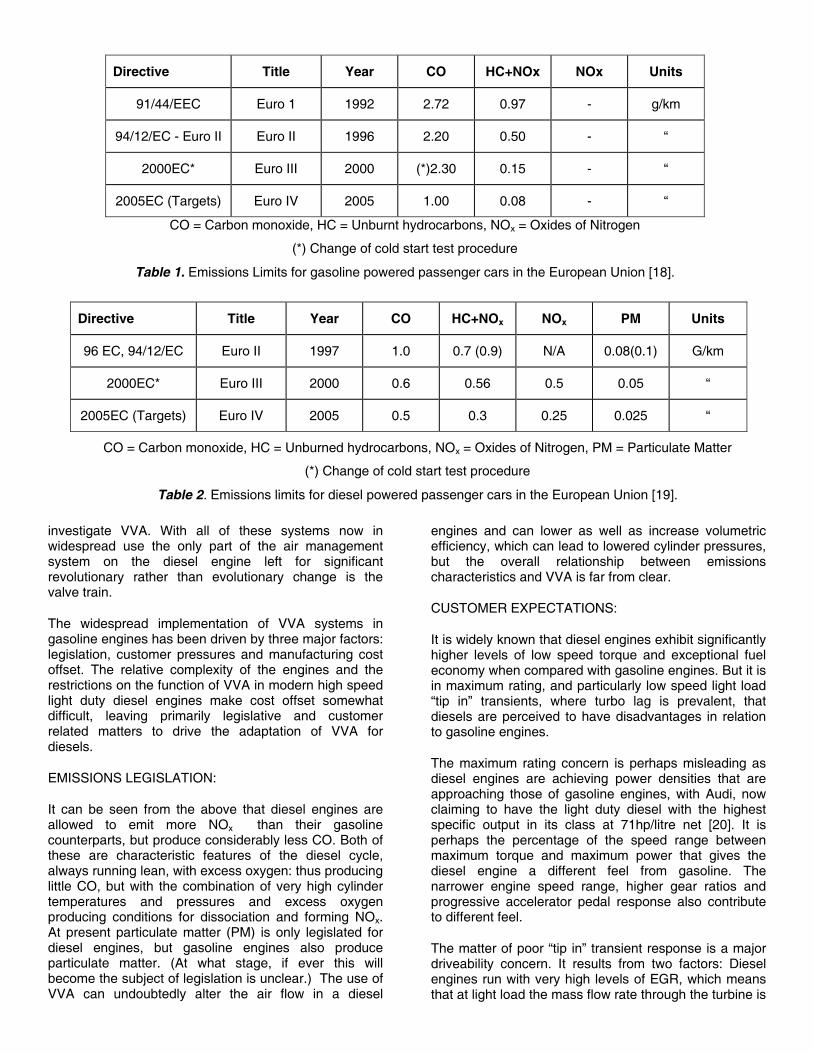
Directive Title Year CO HC+NOx NOx Units
91/44/EEC Euro 1 1992 2.72 0.97 - g/km
94/12/EC - Euro II Euro II 1996 2.20 0.50 - “
2000EC* Euro III 2000 (*)2.30 0.15 - “
2005EC (Targets) Euro IV 2005 1.00 0.08 - “
CO = Carbon monoxide, HC = Unburnt hydrocarbons, NOx = Oxides of Nitrogen
(*) Change of cold start test procedure
Table 1. Emissions Limits for gasoline powered passenger cars in the European Union [18].
Directive Title Year CO HC+NOx NOx PM Units
96 EC, 94/12/EC Euro II 1997 1.0 0.7 (0.9) N/A 0.08(0.1) G/km
2000EC* Euro III 2000 0.6 0.56 0.5 0.05 “
2005EC (Targets) Euro IV 2005 0.5 0.3 0.25 0.025 “
CO = Carbon monoxide, HC = Unburned hydrocarbons, NOx = Oxides of Nitrogen, PM = Particulate Matter
(*) Change of cold start test procedure
Table 2. Emissions limits for diesel powered passenger cars in the European Union [19].
VVA. With all of these systems now in d use the only part of the air management n the diesel engine left for significant
ary rather than evolutionary change is the .
spread implementation of VVA systems in ngines has been driven by three major factors: , customer pressures and manufacturing cost e relative complexity of the engines and the s on the function of VVA in modern high speed diesel engines make cost offset somewhat leaving primarily legislative and customer atters to drive the adaptation of VVA for
S LEGISLATION:
seen from the above that diesel engines are to emit more NOx than their gasoline rts, but produce considerably less CO. Both of characteristic features of the diesel cycle, ning lean, with excess oxygen: thus producing
but with the combination of very high cylinder res and pressures and excess oxygen conditions for dissociation and forming NOx. t particulate matter (PM) is only legislated for gines, but gasoline engines also produce matter. (At what stage, if ever this will e subject of legislation is unclear.) The use of undoubtedly alter the air flow in a diesel
engines and can lower as well as increase volumetric efficiency, which can lead to lowered cylinder pressures, but the overall relationship between emissions characteristics and VVA is far from clear.
CUSTOMER EXPECTATIONS:
It is widely known that diesel engines exhibit significantly higher levels of low speed torque and exceptional fuel economy when compared with gasoline engines. But it is in maximum rating, and particularly low speed light load “tip in” transients, where turbo lag is prevalent, that diesels are perceived to have disadvantages in relation to gasoline engines.
The maximum rating concern is perhaps misleading as diesel engines are achieving power densities that are approaching those of gasoline engines, with Audi, now claiming to have the light duty diesel with the highest specific output in its class at 71hp/litre net [20]. It is perhaps the percentage of the speed range between maximum torque and maximum power that gives the diesel engine a different feel from gasoline. The narrower engine speed range, higher gear ratios and progressive accelerator pedal response also contribute to different feel.
The matter of poor “tip in” transient response is a major driveability concern. It results from two factors: Diesel engines run with very high levels of EGR, which means that at light load the mass flow rate through the turbine is
small and even with the small low inertia turbochargers used today their “spool up” time is noticeable to the driver.
Product differentiation is becoming increasingly important as a marketing tool, both to identify different brand characteristics and provide different levels of product within a brand. The use of V-TEC by Honda has been a successful use of VVA to provide product differentiation (both within Honda’s products and between them and products from other companies.) Product differentiation is a tool in attracting and retaining the interest, and perhaps loyalty, of customers and therefore can act as a sales tool. If this can be used to increase production volumes, economies of scale might also improve the attractiveness of new technologies such as VVA to the manufacturers.
VVA applied to diesels would appear to offer the ability to alter the emissions characteristics of diesel engines, it can improve performance, particularly low speed torque and could provide the opportunity for product differentiation. On the basis of this there would appear to be opportunities that warrant further investigation. It was against this background that DaimlerChrysler and Mechadyne undertook this piece of investigative work.
VVA SYSTEMS FOR DIESELS
Modern, high speed, light duty, diesel engines have very high compression ratios to provide good cold starting characteristics at low ambient temperatures. This means that they have very little clearance between the piston and valves when the piston is close to top dead centre (TDC). This dictates that the valves can have little or no lift at overlap TDC, which in turn means that any VVA system employed can only advance intake opening (IO) and retard exhaust closing (EC) very marginally otherwise valve to piston contact will occur. If the timings are moved in the other directions, negative overlap would occur resulting in undesirable closed cylinder piston motion and pumping work.
As would be expected there are no “clash” constraints with exhaust opening (EO) and intake closing (IC) and these can be moved over very large ranges, if required, to influence volumetric efficiency and work distribution in the cycle.
As a consequence of the above, it can be seen that conventional camshaft phasers are of little use in diesel engines, but systems that provide control over the valve open period, or duration, are applicable.
There are many VVA systems, with varying degrees of complexity, that produce duration control. A selection that appear to be applicable are highlighted here:
1. Direct acting electro-hydraulic systems such as those proposed by Lotus and others [21] [22] and
direct acting electro-magnetic systems as proposed by FEV, Aura and Magnavox [23] [24] [25].
2. Hydraulic “lost lift” systems [26] [27] [28]. 3. Profile generation systems – delta sT, Meta [29]
[30]. 4. Variable velocity systems – Mitchell, Vast [31] [32]
[33].
Whilst a detailed discussion of each of these systems is outside the scope of this paper, a few comments on the suitability of each of these VVA types, for this specific application may be helpful. Any difficulties of implementation arise primarily with the valve lift characteristics these systems produce and how they package in the cylinder head. In all cases cost and complexity are potential concerns.
DIRECT ACTING SYSTEMS:
Electro-hydraulic systems, whilst extremely flexible and powerful development tools are widely regarded as too complex, inefficient and expensive for this type of application, but at least one of the fixed lift electro-magnetic systems is reputed to be nearing production readiness and is therefore worth a little more comment:
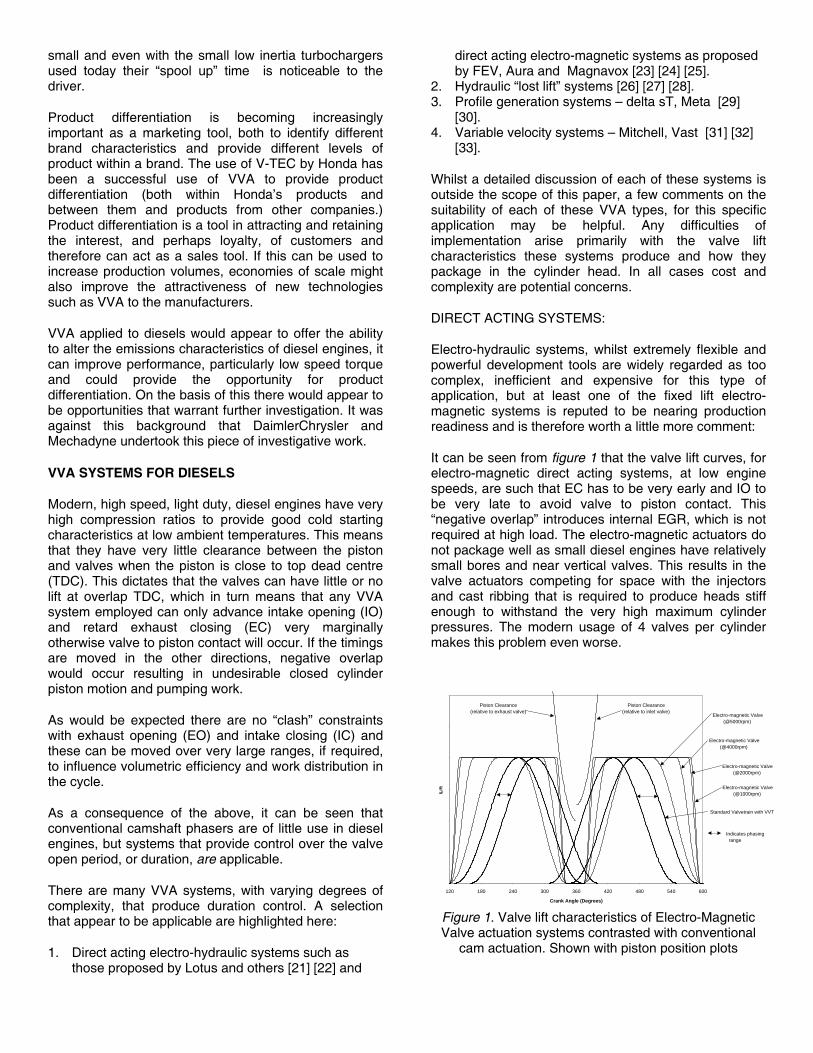
It can be seen from figure 1 that the valve lift curves, for electro-magnetic direct acting systems, at low engine speeds, are such that EC has to be very early and IO to be very late to avoid valve to piston contact. This “negative overlap” introduces internal EGR, which is not required at high load. The electro-magnetic actuators do not package well as small diesel engines have relatively small bores and near vertical valves. This results in the valve actuators competing for space with the injectors and cast ribbing that is required to produce heads stiff enough to withstand the very high maximum cylinder pressures. The modern usage of 4 valves per cylinder makes this problem even worse.
0
2
4
6
8
10
12
120 180 240 300 360 420 480 540 600
Crank Angle (Degrees)
Piston Clearance(relative to exhaust valve)
Piston Clearance(relative to inlet valve)
Electro-magnetic Valve (@4000rpm)
Electro-magnetic Valve (@2000rpm)
Standard Valvetrain with VVT
Electro-magnetic Valve (@1000rpm)
Electro-magnetic Valve (@5000rpm)
Indicates phasing range
Figure 1. Valve lift characteristics of Electro-Magnetic Valve actuation systems contrasted with conventional
cam actuation. Shown with piston position plots
HYDRAULIC “LOST LIFT” SYSTEMS:
Figure 2 shows that the hydraulic lost lift systems primarily control valve closing characteristics, and whilst it is possible to phase shift the cam generating the valve opening such that the opening characteristic is altered, as required with the exhaust valve in a diesel, the extra complexity is unattractive. These systems also have problems with control of valve seating velocity and there would appear to be similar packaging issues to those of the direct acting actuators.
Figure 2. Typical valve lift characteristics of hydraulic “lost lift” systems [26] [27] [28].
PROFILE GENERATION SYSTEMS:
Figure 3a shows the valve opening characteristic of the “delta sT” system from the University of Karlesruhe. This system whilst controlling duration (and lift), has essentially a symmetrical characteristic, which would necessitate a simultaneous phase change to make it applicable. Figure 3b shows the valve opening characteristic for the Meta system. The nature of the mechanism is such that, in its normal application to intake cams it produces large changes in intake closing and lift, with intake opening largely unchanged. It would appear that this mechanism may be reversible to produce changes to valve closing only and might be therefore capable of producing the appropriate duration control functions for application to diesels.
(a) (b)
Figure 3. Typical valve lift characteristics of a) the Delta sT system [29] and b) the META system [30].
However, both the delta sT and Meta systems reduce valve lift in conjunction with reducing duration. Lift control is not fundamentally required by diesel engines and may be undesirable, but the effects of lower lifts at shorter valve open durations on engine operation are at present unknown. The biggest problem with these types of systems is again packaging. Both require considerable space where the injectors would typically be. Also complexity and cost are potential issues.
VARIABLE VELOCITY SYSTEMS:
In comparison with the systems discussed so far, this is a relatively simple family of devices that alter the opening and / or closing timings by cyclically changing the angular velocity of the sections of the camshaft. Figure 4 shows the valve lift characteristics of this type of system, which can be simply configured to influence valve opening or closing timings. This type of system also has relatively few packaging difficulties or complexity problems. Although, they do require head and valve train layout changes and are clearly more complex than phasers or conventional fixed valve train.
Figure 4. Valve lift characteristics for a variable cam
angular velocity system. [33]
On the basis of the foregoing analysis it was decided that the investigation should be carried out using a variable velocity system, based on the work of Mitchell [31] [32].
The Daimler-Benz OM611 engine was chosen as the base engine for the investigation. This is a 2.2 litre four cylinder turbocharged and intercooled diesel engine, which is a good example of a modern high speed direct injection (HSDI) engine, and has been in production since 1998. (See appendix 1)
The project was divided into two major sections, i) mechanical hardware design to investigate the packaging and impact on other engine systems, such as cam and pump drives, and ii) simulation. The simulation work was not intended to be an exhaustive or complete investigation, but rather more an initial piece of work to give an indication of the potential of VVA on diesel engines. Areas investigated were limited to performance and fuel economy and these were only carried out at speeds and loads of particular significance, but other operational characteristics of diesels were identified for future investigation. See appendix 2 for details of other potential areas of benefit from the application of VVA to diesels.
HARDWARE DESIGN
The VVA system chosen is a development of the work of Mitchell, which uses a mechanism to cyclically speed up and slow down the angular motion of a segmented cam [31]. Figure 5 shows a section through a typical mechanism. Figure 6 shows the relative phase of the cam sections and the drive shaft. With appropriate settings of the mechanisms in relation to the cam lobes valve lift characteristics like those shown in figure 7 can be produced. This is the family of curves that was used for the simulation program.
Figure 5. Section through the VET mechanism at 90º intervals [32].
-30
-20
-10
0
10
20
30
0 60 120 180 240 300 360 420 480 540 600 660 720
Crank degrees
3mm
2mm
1mm
Figure 6. Graph of relative cam shell phase versus crank angle [32].
The key features of this type of VVA system, which have implications to the installation, are that space is needed for the individual cam drive mechanisms and that the drive shafts move within the cylinder head. In the application to the OM611 engine these features required a number of changes to be made:
0
1
2
3
4
5
6
7
8
9
0 90 180 270 360 450 540 630 720
Crankshaft Angle
Figure 7. A range of valve lift curves generated by the VET mechanism, as used in the simulation.
Figure 8. VET cam “shell”
To accommodate the mechanisms, which are normally located between the cam lobes, see figure 8, necessitated a change from the standard direct acting tappets to some form of finger follower arrangement. Two schemes were investigated. Figure 9 shows the preferred solution with outboard, stationary, hydraulic lash adjusting pedestals, which required some minor changes to the head casting. Figure 10 shows an alternative that would require minimal changes to the head, but produces a higher overall solution, but one that still fits below the standard cam cover. Both schemes required changes to the cam carrier.
More extensive changes are required to move the drive shaft relative to the cylinder head. This design aspect required a moveable bearing arrangement and some form of drive that accommodated the movement of the shafts. The standard cam drive arrangement is shown in figure 11. The revised drive, figure 12, allows the drive shaft gears to roll around the central, crank driven main drive gear. The drive shafts are supported on arms that pivot around the axis of the main drive gear, projected backwards through the head. Figure 13.
Figure 9. Section through roller finger follower valve train
with outboard lash adjusters.
Figure 10. Section through direct acting finger follower valve train with valve top lash adjusters.
Figure 11. Standard cam and pump drive arrangement.
Figure 12. Revised cam drive arrangement.
Figure 13. Section through control arms.
In the standard engine the high pressure pump for the common rail injection is driven by the idler sprocket, and the low pressure fuel pump and vacuum pump are driven by the camshafts. In the new design, the high pressure pump is instead driven by the main drive gear arrangement and the other pumps by a sub-drive from it.
The design solution allows for full pressure lubrication of all sliding and rotating surfaces and provides for independent control of intake and exhaust cam timings. The design is suitable for the creation of a complete valve train assembly on the carrier which could then be dropped over the ready installed valve and spring assemblies, after the head has been bolted to the block.
SIMULATION MODEL
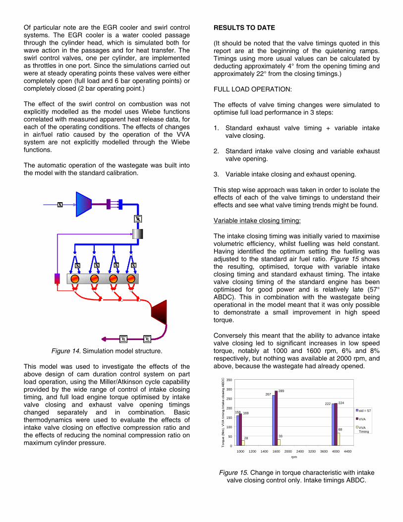
The simulation model of the engine had been in existence for about a year prior to this piece of work and is well correlated with the actual engine and known to produce reliable results. The model structure, implemented in Ricardo’s “Wave” program, is shown in figure 14.
Of particular note are the EGR cooler and swirl control systems. The EGR cooler is a water cooled passage through the cylinder head, which is simulated both for wave action in the passages and for heat transfer. The swirl control valves, one per cylinder, are implemented as throttles in one port. Since the simulations carried out were at steady operating points these valves were either completely open (full load and 6 bar operating points) or completely closed (2 bar operating point.)
The effect of the swirl control on combustion was not explicitly modelled as the model uses Wiebe functions correlated with measured apparent heat release data, for each of the operating conditions. The effects of changes in air/fuel ratio caused by the operation of the VVA system are not explicitly modelled through the Wiebe functions.
The automatic operation of the wastegate was built into the model with the standard calibration.
Figure 14. Simulation model structure.
This model was used to investigate the effects of the above design of cam duration control system on part load operation, using the Miller/Atkinson cycle capability provided by the wide range of control of intake closing timing, and full load engine torque optimised by intake valve closing and exhaust valve opening timings changed separately and in combination. Basic thermodynamics were used to evaluate the effects of intake valve closing on effective compression ratio and the effects of reducing the nominal compression ratio on maximum cylinder pressure.
RESULTS TO DATE
(It should be noted that the valve timings quoted in this report are at the beginning of the quietening ramps. Timings using more usual values can be calculated by deducting approximately 4° from the opening timing and approximately 22° from the closing timings.)
FULL LOAD OPERATION:
The effects of valve timing changes were simulated to optimise full load performance in 3 steps:
1. Standard exhaust valve timing + variable intake valve closing.
2. Standard intake valve closing and variable exhaust valve opening.
3. Variable intake closing and exhaust opening.
This step wise approach was taken in order to isolate the effects of each of the valve timings to understand their effects and see what valve timing trends might be found.
Variable intake closing timing:
The intake closing timing was initially varied to maximise volumetric efficiency, whilst fuelling was held constant. Having identified the optimum setting the fuelling was adjusted to the standard air fuel ratio. Figure 15 shows the resulting, optimised, torque with variable intake closing timing and standard exhaust timing. The intake valve closing timing of the standard engine has been optimised for good power and is relatively late (57° ABDC). This in combination with the wastegate being operational in the model meant that it was only possible to demonstrate a small improvement in high speed torque.
Conversely this meant that the ability to advance intake valve closing led to significant increases in low speed torque, notably at 1000 and 1600 rpm, 6% and 8% respectively, but nothing was available at 2000 rpm, and above, because the wastegate had already opened.
Figure 15. Change in torque characteristic with intake valve closing control only. Intake timings ABDC.
Variable exhaust opening timing:
In order to obtain a good balance between low speed torque and high speed power the turbine was chosen such that at full load the wastegate started to open at 2000 rpm in standard form. Since below this engine speed the turbocharger cannot achieve sufficient boost to open the wastegate, advancing exhaust valve opening provides the opportunity to increase low speed torque by increasing the energy flow to the turbine. The limitation to this is the surge line of the compressor, but this was not reached in any of the simulated conditions.
The negative consequence of advancing exhaust valve opening is the loss of piston expansion work, but as can be seen, this is more than compensated for by the increased boost and consequent ability to burn more fuel doing extra work on the piston in the intake stroke and expansion strokes respectively. For these simulations the air fuel ratio was held constant at the level operated by the standard case.
Figure 16 shows that for the lower speeds, below 2000 rpm, the earlier exhaust valve opening timings, up to 55º earlier than standard, can provide substantial increases in torque. Figures 17 and 18 show the effects of exhaust valve opening timing on full load exhaust gas temperature (EGT) at turbine inlet and boost pressure. It should be noted that for these full load operating conditions the wastegate is open throughout for speeds of 2000 rpm and above.
150
170
190
210
230
250
270
290
310
500 1000 1500 2000 2500 3000 3500 4000 4500rpm
80
102
124
Std = 135
146
168
Figure 16. Full load torque curves with exhaust valve
opening control. Exhaust timings ATDC.
It can be seen from these graphs that at low speeds the EGT at turbine inlet is strongly influenced by exhaust valve opening timing, with earlier opening producing monotonically increasing temperatures with advancing EO – of the order of 10% higher at 1000 and 1600 rpm, with the most advanced timings. At 2000 rpm the effect is less marked, with the maximum temperature occurring with maximum advance, but the temperature is starting to turn up again with very late opening. This trend continues with the higher speeds. At 3200 and 4000 rpm the maximum EGT at turbine inlet still occurs with the earliest EO, but the minimum value of EGT occurs progressively earlier as the speed rises and the increase
in temperature with further retardation of EO becomes larger.
400
450
500
550
600
650
700
70 80 90 100 110 120 130 140 150 160 170 180
Exhaust valve opening timing: degrees after TDC firing
10001600200032004000
Figure 17. Full load exhaust gas temperature at turbine inlet versus exhaust valve opening timing.
For a given air fuel ratio there are two major factors that affect exhaust gas temperature at exhaust valve opening: the extent of the expansion process and the completeness of combustion. The increase in exhaust gas temperature with earlier exhaust valve opening is clear in figure 17, for all speeds. The earlier opening timings allow less expansion and less time for combustion to complete. However the reasons for the up-turn in exhaust gas temperature at the higher speeds and retarded timings is less obvious.
These very late opening timings increase exhaust blow down pumping work by restricting the amount of exhaust gas that is expelled whilst the piston is still doing expansion work. The consequence is that the cylinder pressure is higher at exhaust valve closing, which increases the amount of residual gas retained and thus increases the combustion time, which in turn leads to higher exhaust gas temperature at exhaust valve opening.
100
120
140
160
180
200
220
240
70 80 90 100 110 120 130 140 150 160 170 180
Exhaust valve opening timing: degrees after TDC firing
10001600200032004000
Figure 18. Full load boost pressure versus exhaust valve opening timing.
Variable intake closing and exhaust opening timings:
To investigate this combination the optimal intake valve opening and exhaust valve closings timings established by the separate investigations above were used. The
combustion was simulated using a Wiebe function that accounts for the effects of variations in air fuel ratio on combustion duration, but since the air fuel ratio was kept constant (at the same value as the standard engine calibration) the heat release curve was the same for all cases.
158
267
185
308
150
170
190
210
230
250
270
290
310
330
1000 1200 1400 1600rpm
Std, EO = 135, IC = 57
VVA, EO = 102, IC = 31 (1000rpm), 25 (1600 rpm)
Figure 19. Torque improvement with intake closing and exhaust opening control. Intake closing timings ABDC,
exhaust opening timings ATDC.
The combination of exhaust valve opening and intake valve closing control provides extra control over full load torque and figure 19 shows the improvements found, with their respective timings. The results from all three groups of tests are summarised, in percentage terms in figure 20. This demonstrates the individual and cumulative effects of optimising intake valve closing and exhaust valve opening. For speeds above 2000 rpm and below 4000 rpm the engine and model are Pmax limited and the wastegate is open so the model was incapable of demonstrating benefits in this range.
Figure 20. Summary of torque improvements found from VVA
There are a number of matters that remain unresolved by this work, which are worthy of discussion here to indicate the areas for future work:
The above simulations were all steady state. It is not clear how much of these improvements in torque can be found in transient operation. Intake valve closing timing control can maximise volumetric efficiency irrespective of the boost level, as if the engine were normally aspirated, but with varying ambient conditions. However it is not
clear from the work so far, how much of the extra boost available from the control of exhaust valve opening is usable and translatable into torque in transient operation. It is likely to be a function of the severity of the transient: the greater the rates of change of speed and/or load the smaller the portion of the steady state improvement available.
Opening the exhaust valve earlier offers the opportunity to provide extra energy to the turbine. If the compressor load is less than the turbine shaft output, which would normally be the case in “tip in” transient operation, then this extra energy can be used to accelerate the turbocharger more rapidly. From the work so far there is no indication how significant this effect is.
Re-calibration of an engine with VVA may allow the translation of the increased low speed torque into improved fuel economy by offering the potential to increase the overall gearing of the vehicle. Initial estimates of this are in the 2 to 3% range.
From the above it is apparent that the Pmax limitation and wastegate operation limit the extent of the improvements in engine torque between 2000 and 4000 rpm. The use of VVA may offer the opportunity to use a lower nominal compression ratio. The use of a lower compression ratio would allow a greater trapped mass for a given Pmax, which can be used either to run with a higher air/fuel ratio or to burn more fuel and generate more output. The extent to which this can improve the operation of an engine is as yet unclear.
PART LOAD OPERATION:
Part load operation was investigated at four nominal operating points, 1600 and 2000 rpm at 2 and 6 bar bmep. However, because of the difficulties of trimming other operating parameters to adjust the bmep to a base level it was decided that apart from altering the valve timings all other parameters would be held constant. The results are therefore plotted indicating variations from the nominal operating conditions.
For all of the part load operating conditions the heat release was held constant for a given speed and load combination. The fuel mass and EGR valve settings were held constant. Thus no account was taken of the effects of variations of air/fuel ratio or swirl ratio that might result from the changing of intake valve closing timing. (It is thought that benefits in smoke and bsfc might result from these effects but the modelling has not yet investigated these fully.)
Intake valve closing timing was varied from 565º to 630º, or from 25º to 90º after BDC to investigate “virtual” Miller cycle and Atkinson cycle operation. Please note that these timings are quoted at the bottom of the quietening ramps and more conventionally quoted timings can be calculated by taking 22º from these timings. (The valve opening timings are not subject to these long ramps and
only need a correction of 4º to give a conventional representation.)
The Miller cycle is based on the intake valve closing before BDC. [34] It leads to a reduction in the trapped mass, (for a given constant boost level) and therefore to reduced compression work and thus to a reduction in BSCF. The Atkinson cycle has a similar impact, but by closing the intake valve later than usual. [35] This results in the air being induced into the cylinder and then expelled as the piston moves upwards, in the early part of what would normally be the compression stroke, again reducing the trapped charge, reducing compression work and reducing BSFC.
As already mentioned, fuelling and heat release characteristics were held constant for these part load operating points and the independent variables were allowed to assume new values. Figure 21 shows the changes of BMEP and by implication a corresponding reduction in BSFC at all operating conditions simulated.
At 2 bar BMEP, as expected both Miller and Atkinson cycle reduced the air flow into the engine, although the benefits from the late intake valve closing were smaller than those shown with the early intake valve closing. This may be explained by the fact that in the late intake valve closing case pumping work is done on inducing and expelling the air.
At 6 bar BMEP, the benefits shown by the simulation were very small improvements in BMEP for Miller or early intake valve closing and larger decreases in BMEP for Atkinson cycle operation. This is explained by the fact that at this higher load the pumping loop is smaller, with less negative work. As the load and boost pressure rise so the pumping loop turns progressively to positive work.
Figure 21. Changes of part load bmep with varying speed, load and intake valve closing timing. The fuelling
is held constant at each speed/load.
Figure 22 shows the pumping loop from the simulation of the 2 bar bmep, 2000 rpm operating point. The areas that contribute to the reduction in pumping work are apparent. It can also be seen that since compression starts at a lower pressure the compression work done is reduced.
It may be of interest to note the upturn in cylinder pressure at the end of the exhaust stroke. This is a consequence of the very limited valve lift possible at TDC, and the resultant flow restriction at the exhaust valve.
0.75
0.8
0.85
0.9
0.95
1
1.05
1.1
1.15
1.2
1.25
1 3 5 7 9 11 13 15 17
Cylinder volume / clearance volume
19
Standard valve timing EIVC
Figure 22. Pumping loops for the standard valve timing and early intake valve closing at 2 bar bmep 2000 rpm.
EIVC timing is 25° ABDC.
THE EFFECTS OF VALVE TIMING ON EFFECTIVE COMPRESSION RATIO
The major reason for the very high geometric, or nominal compression ratio, CRnom, in modern diesel engines is that they need to be able to start at very low ambient temperatures, typically down to –25º C and even lower for military vehicles. This requires the CRnom to be several ratios higher than would be required for the engine to run optimally once started and warmed up. If the CRnom is made low, for good normal operation, this produces cranking cylinder temperatures and pressures that are sufficiently low to make very low temperature starting difficult, if not impossible.
Cold starting quality is strongly influenced by the air temperature in the cylinder at the end of the compression stroke and is a function of compression ratio and intake valve closing timing. Since fixed intake valve closing is usually significantly after BDC, in order to benefit from charge dynamic effects at higher engine speeds, at cranking speeds some of the air is pumped out of the cylinder between BDC and intake valve closing. Also under cranking conditions the compression process is relatively slow, so heat loss from the charge to the (cold) cylinder, piston and cylinder head can be significant. The reduced trapped mass and increased heat transfer reduce compression temperatures. Advancing intake valve closing towards BDC increases the trapped mass and therefore the temperature at the end of compression. It has been reported that on a truck engine a change of intake valve closing from 44º to 23º after BDC allowed a reduction of compression ratio from 17:1 to 15:1 with starting performance maintained at –18ºC [36].
Figure 23 shows the effect of intake valve closing on the effective compression ratio of an engine. In this case the
engine has a nominal compression ratio of 20:1 and the intake valves closing at 58º after BDC. Advancing intake closing to 25º after BDC increases the effective compression ratio by 3 ratios.
10
11
12
13
14
15
16
17
18
19
20
565 575 585 595 605 615 625
IVC - Crank Angle aTDC Firing
598.1
Figure 23. Effect of intake valve closing timing on effective compression ratio.
The high compression ratio required for starting is often higher than required for best economy as the thermodynamic gains of high compression ratio are outweighed by the consequent reduction in mechanical efficiency [4]. The use of VVT to increase the effective compression ratio allows the nominal compression ratio of the engine to be reduced, which not only maintains or improves cold starting, but also has implications to output:
It is not uncommon for modern diesel engines to have upper cylinder pressure limits imposed by structural limitations. The reduction of the nominal compression ratio allows output levels to be maintained with lower peak cylinder pressures, Pmax, or increased output for a similar peak cylinder pressure [34]:
To increase engine power output requires either the torque at high speed to be increased, if the engine speed range is limited, or the torque to be maintained and the speed range to be extended. Since the upper speed limit of a modern diesel engine is usually imposed by combustion speed limitations there appears to be little opportunity to extend the speed range using VVT.
However, since VVT can allow an engine to operate with a lower nominal compression ratio, the BMEP can theoretically be increased, (by increasing the boost levels) within the same maximum cylinder pressure limitations. It has been suggested that raising and flattening the torque curve, of a diesel engine, should be possible with variable valve actuation [34] [4]. This would result in increased power as well as improving the shape of the torque curve.
CONCLUSIONS
1. A design study has been carried out that indicates that a feasible design for a variable duration cam system can be integrated into a modern European 4
valve per cylinder diesel engine, but minor changes to the head and a different cam drive arrangement are needed.
2. At the low speeds and loads simulated, 1600 and 2000 rpm, early intake valve closing decreased bsfc. The improvements being greatest (approx 2.3%) at low loads (at or below 2 bar bmep) and decreasing as load increases.
3. At the low speeds and loads simulated, 1600 and 2000 rpm, late intake valve closing decreased bsfc, these improvements being greatest (approx 1%) at low loads (at or below 2 bar bmep) and decreasing as load increases, to the extent that at 6 bar bmep this strategy is counterproductive.
4. Simulation of steady state, full load, operation at 1000 rpm and 1600 rpm demonstrated increases of torque:
• from 6.3 to 8.2% by advancing intake valve closing
• from 8.6 to 12.6% by advancing exhaust valve opening.
• from 15.4 to 16.4% by advancing exhaust valve opening and intake valve closing.
ACKNOWLEDGEMENTS
Thanks are owed to DaimlerChrysler Berlin and Mechadyne International who jointly funded this piece of work and to those in DaimlerChrysler Stuttgart who supported the project.
APPENDIX 1 - BASE ENGINE SPECIFICATION
4 cylinder in-line, 4 valves per cylinder twin overhead camshaft with direct acting tappets.
Overall:
• Swept volume 2151 cm3.
• Compression ratio 20:1
• Bore 88mm, stroke 88.4mm.
• Standard output 92kW at 4200 rpm.
Systems:
• Swirl control.
• Cooled EGR.
• Boost controlled wastegate.
• Turbocharger: Allied Signal T20.
• Water to air intercooler
• “Common Rail” injection
APPENDIX 2 – FUTURE WORK
It can be seen from the foregoing that there are still many questions to be answered about the impact of VVA on turbocharged diesel engines. It is intended that the authors will seek answers to many of these questions. Some of the future work areas are highlighted below:
INVESTIGATION OF REDUCED NOMINAL COMPRESSION RATIO:
Cold starting.
Control of maximum cylinder pressure.
Increased maximum power and extended torque characteristics.
Control of emissions.
TURBOCHARGER OPERATION:
Transient operation: Variable exhaust valve opening vs. Variable geometry turbines.
Turbocharger acceleration.
Exhaust blow down pumping work.
Alternative turbocharger matching strategies.
Moving work from the expansion stroke to the intake stroke.
Using intake valve closing to limit boost/trapped mass instead of a wastegate.
Delaying exhaust opening to reduce boost.
BIBLIOGRAPHY
[1] Gray C., (1988) A Review of Variable Engine Valve Timing. SAE paper 880386.
[2] Dresner, T. and Barkan, P (1989) A Review and classification of Variable Valve Timing Mechanisms. SAE paper 890674.
[3] Ahmad, T. and Theobald, M.A. (1989) A Survey of Variable-Valve-Actuation Technology. SAE paper 891674.
[4] Stone, C.R. and Kwan, E. (1989) Variable Valve Actuation mechanisms and the potential for their application. SAE paper 890673.
[5] Steinberg, R., Lenz, I., Koehnlein, G., Scheidt, M., Saupe, T and Buchinger, W. (1998) A fully continuous variable valve timing concept for intake and exhaust phasing. SAE paper 980767.
[6] Grohn, M. (1990) The new camshaft adjustment system by Mercedes Benz – Design and application in 4 valve engines. SAE paper 901727.
[7] Bassi, A., Arcari, F. and Perrone, F. (1985) CEM - The Alfa Romeo engine management system – Design concepts – Trends for the future. SAE paper 850290.
[8] Leone, T.G., Christenson, E.J. and Stein, R.A., (1996) Comparison of variable camshaft timing strategies at part load. SAE paper 960584.
[9] Stein, R.A., Galietti, K.M. and Leone, T.G., (1995) Dual equal VCT – A variable camshaft timing strategy for improved fuel economy and emissions. SAE paper 950975.
[10] Inoue, K., Nagahiro, K., Ajiki, Y. and Kishi, N. (1989) A high power, wide torque range efficient engine with a newly developed variable valve lift and timing mechanism. SAE paper 890675.
[11] Anon,“MIVEC”(1992) Mitsubishi’s new “MIVEC” system for high efficiency at all engine speeds for more power and better mileage. Japan Autotech report vol. 152, September 20, 1992. Pages 18 to 22.
[12] Allen, J. and Dopson, C. (1991) The development and application of two camshaft profile switching systems. Institution of Mechanical Engineers. Seminar “Variable Geometry Engines,” London, June 1991. Paper 8, pages 81 to 93.
[13] Buuck, B. and Hampton, K., (1997) Engine trends and valvetrain systems for improved performance, fuel economy and emissions. ASM. Paper 1, session 1. Proceedings of the international symposium on valve train system design and materials. Detroit 14-15th of April 1997.
[14] Charlton, S.J., Stone C.R., Leonard, H.K., Elliott, C. and Newman, M.J. (1991) Transient simulation of a highly turbocharged diesel engine with variable valve timing. Paper C430/016, Conference “Computers in engine technology. September 1991, Cambridge, UK. Institution of Mechanical Engineers.
[15] Leonard, H.J., Stone, C.R, Charlton, S.J, Johnstone, D., elliot, C. and Newman M. (1993) Design and analysis of a roller follower variable valve timing system. SAE paper 930824.
[16] Benajes, J., Reyes, E. and Lujan, J.M., (1996) Intake valve pre-lift effect on the performance of a turbocharged diesel engine. SAE paper 960950.
[17] Bazari, Z. and French, B. (1993) Performance and emissions trade-offs for a HSDI diesel engine - An optimisation study. SAE paper 930592.
[18] Knibb, Gormezzano and Partners (1998) Legislation – Vehicle emissions and fuels. Report commissioned by Mechadyne Ltd. KGP , Derby UK.
[19] Pethers P. (1997) The business perspective – Engineering affordable solutions to the HSDI Diesel Euro IV challenge. I. Mech. E. Conference: Euro IV challenge – Future technologies and systems. 3-4 December 1997, London.
[20] Anon, “FT Automotive Environment Analyst” (1999 ) Financial Times Automotive Environment Analyst. Issue 54, page 12, July 1999.
[21] Griffiths P. J., Mistry K.N. and Philips B.D.A., (1988) An electro-hydraulic valve operating system for engine research and development. Experimental methods in engine research and development, I.Mech.E. Seminar 1988.
[22] Wilson, N., Dobson, C. and Muddell, G. (1993) Active valve train system promises to eliminate camshafts. Institution of Mechanical Engineers. Automotive Engineer Feb/Mar 1993, pages 42 to 44.
[23] Kreuter, P., Heuser, P, and Schebitz, M. (1992) Strategies to improve SI engine performance by means of variable intake lift, timing and duration. SAE paper 920449.
[24] Morinigo, F., Stuart K. and Schneider, L., (1997) Variables of electromagnetic valve actuator performance. Engine technology international, November 1997, pages 84 to 88.
[25] Anon, “Magnavox” (1988) A proposal for the Magnavox Electronic Valve System. Document serial number MX-18-145, published by Magnavox (a USA subsidiary of Phillips) 15/11/88.
[26] Lee, J-C., Lee, C-W., Nitkiewicz, J.A., (1995) The application of a lost motion VVT system to a DOHC SI engine. SAE paper 950816.
[27] Lenz, H. P., Geringer, B., Smetana, G. and Dachs, A., (1989) Initial test results of an electro-hydraulic variable valve actuation system on a firing engine. SAE paper 890678.
[28] Urata, Y., Umiyama, H., Shimizu, K., Fujiyoshi, Y., Sono, H. and Fukuo, K., (1993), A study of vehicle equipped with non-throttling S.I. engine with early intake valve closing mechanism. SAE paper 930820.
[29] Berg, M., Kachel, G. and Kuhn, P., (1997) Mechanical Fully-Flexible Valve Control with delta-sT. SAE paper 970251.
[30] Kreuter, P., Heuser, P., Murmann, J., (1998) The META VVH system - A continuously variable valve timing system. SAE paper 980765.
[31] Griffiths P. J. and Mistry K.N., (1988) Variable valve timing for fuel economy improvement, the Mitchell system. SAE paper 880392.
[32] Lancefield, T.M., Gayler, R.J. and Chattopadhay, (1993) The practical application and effects of a Variable Valve Timing System. SAE paper 930825.
[33] Bertsch, A and Hannibal, W. (1997) Vast – A new variable valve timing system for vehicle engines. SAE paper 980769.
[34] Watson, N. and Janota, M.S., (1982) Turbocharging the internal combustion engine. Section 11.2 pages 381 to 383. Macmillan Press, 1982.
[36] Holmer, E. and Haggh, B., (1969) The turbo-charged diesel as a road transport power unit. Proceedings of the Institution of Mechanical Engineers, Vol. 184 part 3P, pages 55 to 62, 1969-7