*[email protected]The CHEOPS' instrument On-Ground calibration system F. P. Wildi a* , B. Chazelas a , A. Deline a , M. Sordet a , M. Sarajlic b a Observatory of Geneva, 51 ch. des Maillettes, CH-1290 Sauverny, Switzerland a Swiss Optics Systems, av. Général-Guisan 61, 1400 Yverdon-les-Bains, Switzerland ABSTRACT The CHaracterising ExOPlanet Satellite (CHEOPS) is a joint ESA-Switzerland space mission dedicated to the search for exoplanet photometric transits. Its launch readiness is expected at the end of 2017. The CHEOPS instrument will be the first space telescope dedicated to search for transits on bright stars already known to host planets. By being able to point at nearly any location on the sky, it will provide the unique capability of determining accurate radii for a subset of those planets for which the mass has already been estimated from ground-based spectroscopic surveys. To reach its goals CHEOPS will measure photometric signals with a precision of 20 ppm in 6 hours of integration time for a 9th magnitude star. This corresponds to a signal-to-noise ratio of 5 for a transit of an Earth-sized planet orbiting a solar-sized star. Achieving the precision goal requires thorough post-processing of the data acquired by the CHEOPS' instrument system (CIS) in order to remove as much as possible the instrument's signature. To this purpose, a rigorous calibration campaign will be conducted after the CIS tests in order to measure, its behavior under the different environmental conditions. The main tool of this calibration campaign is a custom-made calibration system that will inject a stimulus beam in the CIS and measure its response to the variation of electrical and environmental parameters. These variations will be compiled in a correction model. Ultimately, the CIS photometric performance will be measured on an artificial star, applying the correction model This paper addresses the requirements applicable to the calibration system, its design and its design performance. Keywords: exoplanets, photometric transits, stable light source 1. INTRODUCTION The main science goal of CHEOPS is to measure the photometric transit of exoplanets with radii typically ranging from 1 to 6 Earth radii orbiting bright stars. To reach this goal CHEOPS need to have a photometric stability of 20 ppm in 6 hours of integration time for a 9th magnitude star The payload is engineered to be as immune as possible form the environmental changes: A baffle protects it from the high brightness of its low earth orbit surroundings, the detector and its read-out electronics (ROE) are thermally controlled, the detector bias voltages circuits are state-of-the-art, etc. However, the control of the environmental parameters is not perfect and not comprehensive. Therefore, there is a need to calibrate the CHEOPS instrument system (CIS) behavior. I.e. to measure the variations of this behavior as a function of the environmental variables. The key parameter that describes this behavior is the photonic gain. The photonic gain is the ratio between the numerical signal produced by the CIS and the number of photons from the observed stellar object that have entered the telescope pupil. To this purpose, a significant effort has been placed in the development of a CIS calibration bench. This bench simulates a very stable star that can be steered to any point of the field of view. The signal produced by the CIS can be measured and a model of the gain as a function of the different environmental parameters can be built. 2. THE CHEOPS MISSION The CHaracterising ExOPlanet Satellite (CHEOPS) is a joint ESA-Switzerland space mission dedicated to the characterization of exoplanet transits by means of high precision photometry [1]. Its launch is expected end of 2017. CHEOPS will be the first space telescope dedicated to search for transits on bright stars already known to host planets. By being able to point at nearly any location on the sky, it will provide the unique capability of determining accurate radii for a subset of those planets for which the mass has already been estimated from ground-based spectroscopic surveys. CHEOPS will also provide precision radii for new planets discovered by the next generation ground-based
The CHEOPS' instrument On-Ground calibration system F. P. Wildia*, B. Chazelasa, A. Delinea, M. Sordeta, M. Sarajlicb
a Observatory of Geneva, 51 ch. des Maillettes, CH-1290 Sauverny, Switzerland a Swiss Optics Systems, av. Général-Guisan 61, 1400 Yverdon-les-Bains, Switzerland
ABSTRACT
The CHaracterising ExOPlanet Satellite (CHEOPS) is a joint ESA-Switzerland space mission dedicated to the search for exoplanet photometric transits. Its launch readiness is expected at the end of 2017. The CHEOPS instrument will be the first space telescope dedicated to search for transits on bright stars already known to host planets. By being able to point at nearly any location on the sky, it will provide the unique capability of determining accurate radii for a subset of those planets for which the mass has already been estimated from ground-based spectroscopic surveys. To reach its goals CHEOPS will measure photometric signals with a precision of 20 ppm in 6 hours of integration time for a 9th magnitude star. This corresponds to a signal-to-noise ratio of 5 for a transit of an Earth-sized planet orbiting a solar-sized star.
Achieving the precision goal requires thorough post-processing of the data acquired by the CHEOPS' instrument system (CIS) in order to remove as much as possible the instrument's signature. To this purpose, a rigorous calibration campaign will be conducted after the CIS tests in order to measure, its behavior under the different environmental conditions.
The main tool of this calibration campaign is a custom-made calibration system that will inject a stimulus beam in the CIS and measure its response to the variation of electrical and environmental parameters. These variations will be compiled in a correction model. Ultimately, the CIS photometric performance will be measured on an artificial star, applying the correction model
This paper addresses the requirements applicable to the calibration system, its design and its design performance.
The main science goal of CHEOPS is to measure the photometric transit of exoplanets with radii typically ranging from 1 to 6 Earth radii orbiting bright stars. To reach this goal CHEOPS need to have a photometric stability of 20 ppm in 6 hours of integration time for a 9th magnitude star
The payload is engineered to be as immune as possible form the environmental changes: A baffle protects it from the high brightness of its low earth orbit surroundings, the detector and its read-out electronics (ROE) are thermally controlled, the detector bias voltages circuits are state-of-the-art, etc.
However, the control of the environmental parameters is not perfect and not comprehensive. Therefore, there is a need to calibrate the CHEOPS instrument system (CIS) behavior. I.e. to measure the variations of this behavior as a function of the environmental variables. The key parameter that describes this behavior is the photonic gain. The photonic gain is the ratio between the numerical signal produced by the CIS and the number of photons from the observed stellar object that have entered the telescope pupil.
To this purpose, a significant effort has been placed in the development of a CIS calibration bench. This bench simulates a very stable star that can be steered to any point of the field of view. The signal produced by the CIS can be measured and a model of the gain as a function of the different environmental parameters can be built.
2. THE CHEOPS MISSION
The CHaracterising ExOPlanet Satellite (CHEOPS) is a joint ESA-Switzerland space mission dedicated to the characterization of exoplanet transits by means of high precision photometry [1]. Its launch is expected end of 2017. CHEOPS will be the first space telescope dedicated to search for transits on bright stars already known to host planets. By being able to point at nearly any location on the sky, it will provide the unique capability of determining accurate radii for a subset of those planets for which the mass has already been estimated from ground-based spectroscopic surveys. CHEOPS will also provide precision radii for new planets discovered by the next generation ground-based
transits surveys (Neptune-size and smaller). The main science goals of the CHEOPS mission is to study the structure of exoplanets with radii typically ranging from 1 to 6 Earth radii orbiting bright stars. To reach its goals CHEOPS will measure photometric signals with a precision of 20 ppm in 6 hours of integration time for a 9th magnitude star. This corresponds to a signal to noise of 5 for a transit of an Earth-sized planet orbiting a solar-sized star (0.9 solar radii). This precision will be achieved by using a single frame-transfer backside illuminated CCD detector cooled to 233K (-40C) and stabilized within ~10 mK. The CHEOPS optical design is based on a Ritchey-Chretien style telescope with 300 mm effective aperture diameter, which provides a defocussed image of the target star while minimizing stray light using a field stop and baffle system. As CHEOPS will be in a LEO orbit, straylight suppression is a key point to allow the observation of faint stars. The telescope will be the only payload on a spacecraft platform providing pointing stability of < 8 arcsec rms. It represents a breakthrough opportunity in furthering our understanding of the formation and evolution of planetary systems.
3. THE CHEOPS INSTRUMENT SYSTEM
The CHEOPS payload is made of a single instrument called CIS [2]- It is a space telescope of 300mm clear aperture diameter see figure 1 composed of four main units:
1) The Baffle and Cover Assembly minimizes stray-light and includes a protective cover and release mechanism. 1. The Optical Telescope Assembly includes the structure carrying the telescope, the Back End Optics, the Focal
Plane Module, and the radiators. In order to minimize the impact of thermo-elastic deformations on the instrument pointing, the optical heads of the platform star trackers will be mounted on the OTA, close to the isostatic mounts of the instrument.
2) The Sensor Electronics Module 3) The Back End Electronics
Table 1. CHEOPS Instrument System (CIS) main specifications
Instrument total Mass <60kg including system margin
Instrument total nominal power <60W orbit averaged including margin Photometric stability 20 ppm over 6 hour transit
Figure 1. The CHEOPS satellite L/h, and a cut through the CHEOPS instrument system R/h.
4. THE CHEOPS CALIBRATION SYSTEM REQUIREMENTS
Before the requirements applicable to the bench were established, a calibration plan was produced where all the measurements planned to establish the instrument's signature were identified. The bench requirements were derived to make all the measurements called for in the calibration plan possible. Below is a list of the main requirements:
• produce an artificial star with a white stellar-like spectrum
• fully illuminate the pupil over the whole field
• 150nm wave front error (on the calibration system only)
• point the star to any point in the CIS field
• vary the magnitude of the star
• simulate the satellite wobble
• keep the star twice as stable in magnitude as the stability expected from the CIS
• provide a flat fields source o with a flatness better than 500ppm across the field o wide band and narrow band
• fully automatized to the point where it can execute full sets of calibrations on its own and reduce the data.
5. OPTICAL IMPLEMENTATION
Optically the bench features
• a focal module where the point source creating the artificial star is located. A flat field source is also provided in the form of an integrating sphere
• a large off-axis 2579mm focal length Ø457mm parabola acting as a collimator to send the point-like artificial star to infinity
• a large folding flat mounted on a tip-tilt stage to explore the full field of view
• a large window to separate the bench itself in ambient air from the CIS sitting in a space environment simulator. Physically, this window is not part of the bench but we include it here because it is part of the bench performance budget.
Figure 2. Top view of the calibration bench with the optical beam rendered in blue .
The focal point module
This module is made of elements. Only one can be at the collimator focus at any time.
a) a flat-field source in the form of a high grade integrating sphere with a high Øext/Øport ratio to insure good center-to-edge flatness
b) a point-source unit. This unit incorporates a number of functions a. An artificial star simulating the object of interest in the field
b. An apodizer which role is to transform the Gaussian-like energy distribution in beam coming out of the star fiber into a flat energy distribution as expected in flight. See section "optical budgets"
c. A pierced mirror reflecting part on the light from the artificial star into a sensing fiber. See section "super stable source".
d. A mask featuring 4 fiducials used to maintain pupil centration. See section "optical budgets"
6. OPTICAL BUDGETS
Wave front error
To allow for precision photometry on bright stars, the CIS is defocused by several waves so that the photon flux is spread over approximately 700 pixels. It is therefore rather difficult to define maximal wave front error in terms of how
it will degrade the PSF. We conservatively defined the max bench WFE to be λ/4 @632nm.
Our system has 2 mirrors (the OAP and the fold flat) and 3 diopters (a neutral density, the apodizer and the vacuum
chamber window). Each component WFE is specified be ≤ λ/8. The only powered component is the OAP. Therefore the input module v.s. OAP alignment is the only alignment that impacts the final WFE. The assumed temperature variation
of ±1°C in the clean room generates a negligible contribution to the WFE.
Photometry
One of the goals of the CHEOPS payload calibration is the measurement of its photometric. Therefore, all attentions was paid to have the most stable optical power injected in the payload telescope. The stability of optical power is determined not only by the stability of our light source (see section below), but by the stability of the optical power coupling between the calibration bench and the payload. A variation of this coupling is produced if there is a beam shift and the field in the pupil is not homogenous. This variation will depend on:
• Optical field homogeneity in the beam
• The amount of beam shift on the bench surfaces and between the bench and the CIS
• The amount of beam shift on the vacuum enclosure entrance window and the homogeneity of that transmission
Figure 3. Diagram showing the photometry problem: The calibration bench pupil is represented in red. The inhomogeneous irradiance in this pupil is represented in gray tones. The CIS pupil is represented in blue. The optical power measured by the CIS is the integral of the optical field entering its pupil. If there is a motion between the two pupils due for instance to some motion between the vacuum enclosure holding the payload and the calibration bench outside the enclosure, then the integral of the field in the blue pupil will vary and so will the photometric signal given by the CIS.
Because of the need to have an unresolved point source to simulate the star, we are using a monomode fiber. Therefore the field distribution across the pupil will be close to Gaussian. This behavior is clearly unacceptable and we have therefore introduced an apodizer in the system.
To make this apodizer as performing as possible, we have accurately measured the far field distribution of the fibers we will use in many color bands. It turned out that the Gaussian apodizer is not sufficient for the precision we need. From the far field distributions we have been able to develop a free from apodizer that will make the pupil look flat to the CIS. This pupil is not achromatic, but it appears flat to the CIS, taking into account the source spectrum, the
transmission/reflection T(λ) anf R(λ) of the different diopters and mirrors in the full system and the CHEOPS's CCD spectral sensitivity.
Figure 4. Effect of the apodizer. The L/h figure shows the spectral distribution across the pupil. The pupil center is essentially red while the exterior is blue. The center figure shows the natural (green) and corrected (blue) distribution of intensity across the pupil, normalized at the pupil center. The total transmission is 15.8%. The R/h figure is a close-up of the former one showing a departure from the ideal flatness by 1.1%
This apodizer has however been optimized following the hypothesis that the beam at the output of the fiber is Gaussian at any wavelength, Measurement proved this is not true and that we can estimate the residual pupil inhomogeneity in the 5-10% range. The repartition of this inhomogeneity is more or less radially sinusoidal. The effect of a pupil translation on the photometry is shown on figure 5
Figure 5. Effects of the pupil inhomogeneity. The photometric impact of the pupil translation is very limited it will be easy, given the system to lock the pupil to maintain the translation below 2 mm. It also shows that the jitter simulation moving the fiber head will not introduce significant photometric variations (movement < 200 microns)
The flattening obtained is not sufficient to be immune to the pupil shift expected during the calibration. Therefore a pupil centering scheme is implemented in the system: A set of 4 fiducial stars placed at 90° on a small circle around the reference star have been added. A mask is placed closely placed in front of these fiducials. The purpose of this mask is to make the pupil illumination of this fiducials as contrasted across the pupil as possible.
Figure 6: Schematic diagram of the pupil centering scheme. L/h figure: On the focal plane the central "star" emits and unobstructed beam. Two fiducial stars emit beam that are partially obstructed by a mask. Center figure: View of top fiducial beam at the pupil level. Because of the mask, the fiducial pupil is not uniformly illuminated. If the relative position between the calibration system pupil and the CHEOPS pupil changes, the amount to light that is coupled between the two systems will change. R/h figure: image of the central star and the 4 fiducials in the CHEOPS focal plane. If the relative position between the calibration system pupil and the CHEOPS pupil changes vertically, the ratio between the top half-moon and the bottom half moon will change and this ratio can be used as feedback in a control loop
The impact of the vacuum enclosure window anti-reflection coating has also been evaluated. The homogeneity of the coating has been optimized by the manufacturer designing as special mask during the coating. The reflectivity of the coating has been measured across the diameter and can be seen on figure 7
Figure 7. On the right the measured reflection of the AR coating on the sample that has been used to tune the coating mask. It has been measured on a different substrate but is representative of the uniformity of the real coating. On the right the effect of the translation of the test telescope pupil with respect to the window, on the measured flux. This is giving a < 3ppm contribution to the error budget as the movement of the pupil during one measurement run should be < 20 mm.
Focus
A ±1° variation of the ambient temperature will produce up to 50 microns in focus. This will lead to a negligible warfront deformation but, will bring photometric variations. The collimator pupil diameter will vary but the total flux will stay constant. Thus the actual flux collected by the tested telescope would vary. Simple Geometry yield that a 10 micron defocus will produce ~ 8ppm photometric variations.
The system photometric budget, including all aspects above is presented in table 2 below. The rms total is 18.5ppm and it is dominated by the effect of the coating homogeneity on the parabola and the folding flat. It is actually the beam shift between bench and payload that will cause the use of different parts of these mirror. A careful design of the way the payload is mounted in the vacuum enclosure should allow a relative motion to the calibration bench significantly small than the budgeted 1° p2v and provide for performance closer to the 10ppm goal.
object focal plane
mask plane
CHEOPS
pupil
bench half pupil plane
Table 2. Photometric budget.
Drift noises that do not average with time
Non uniformity of the pupil apodization 5.0 ppm
Non uniformity of the TVC window 3.0 ppm
Non uniformity of the parabola coating 8.9 ppm
Non uniformity of the coating Flat folding mirror 8.9 ppm
Thermal focus changes 8.0 ppm
Noise that averages out with time
Photon noise on the CCD (1s) 147.7 ppm
photon noise on the ultra-stable source detector (1s) 3.6 ppm
Noise on the ultra-stable source detector measurement chain in closed loop(@1Hz) 23.0 ppm
Ultra-stable source detector stability 3.0 ppm
Total of the white noise averaged over 6hours 9.3 ppm
Grand total 18.5 ppm
7. SUPER STABLE SOURCE
For CHEOPS, we have chosen to use an LDLS [4] as primary source because its 10'000K color temperature offers both a flat spectrum across the visible and a high radiance that allows a sizable amount of power to be coupled even in a monomode fiber. We experimentally determined that this lamp a luminous power output variation of in the 1-3% p2v range, i.e. 10'000 to 30'000ppm over the 6 hours which is the duration over which the CHEOPS performance is specified. It is obvious that a lamp such as listed above cannot be used without having its flux stabilized. For this reason, the Observatory of Geneva has developed a luminous power control system that transforms the LDLS in what we call Super Stable Source [3]. Its noise for consecutive 8s exposures is barely above 5ppm.
Figure 8. L/h: 3D rendering of the super stable source. R/h: performance of this source with stabilization. Stability is about 3ppm when signal averaged in 1min bins
8. OPTO-MECHANICAL IMPLEMENTATION
Figure 9. The CHEOPS calibration bench. After it exits the bench at the bottom of the image, the beam goes through a window into the space environment simulator.
Focal plane module
To fulfill the need to simulate the satellite jitter and to keep the star pin-pointed in average on the detector we are using a hexapod to position the focal plane module. It allows transverse motions in the two axes perpendicular to the optical axis. In addition, it allows to move the star along the optical axis for the focusing of the collimator during alignments.
The crucial point with this hexapod is that it also allow to modify the distribution of the field intensity in the pupil: Indeed, by tilting the artificial star fiber around its tip, the distribution of the field on the pupil is shifted (see figure 3) leaving the image in place. We goal will be to center the field distribution on the CHEOPS pupil, not the bench's and
keep it centered. To this purpose the hexapod's θx and θy degrees of freedom (DOF) are used. The θz DOF is the only DOF that is not used
Figure 10. The focal plane module. From the left to the right on the L/h figure (resp. bottom to top on the center image): The artificial star+fiducials ferrule, the pupil alignment mask, the pick-off mirror for the photometer in the super stable source feedback loop and the apodizer. The R/h picture shows the focal plane ferrule with the central star and the four fiducials. The dot at the bottom right is the fiber collecting the light from the pick-off mirror. The screws are holding the anti-reflection mask need to control ghosts.
Collimator
The collimator is a full pupil off-axis design with about 2500mm bfl. Its mount is uncomplicated since it is the reference element on our bench and therefore does not have to be aligned.
Tip-tilt (folding) mirror
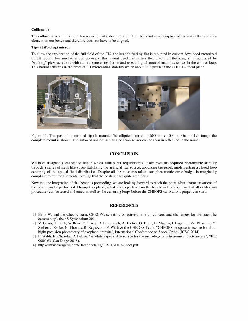
To allow the exploration of the full field of the CIS, the bench's folding flat is mounted in custom developed motorized tip-tilt mount. For resolution and accuracy, this mount used frictionless flex pivots on the axes, it is motorized by "walking" piezo actuators with sub-nanometer resolution and uses a digital autocollimator as sensor in the control loop. This mount achieves in the order of 0.1 microradian stability which about 0.02 pixels in the CHEOPS focal plane.
Figure 11. The position-controlled tip-tilt mount. The elliptical mirror is 600mm x 400mm. On the L/h image the complete mount is shown. The auto-collimator used as a position sensor can be seen in reflection in the mirror
CONCLUSION
We have designed a calibration bench which fulfills our requirements. It achieves the required photometric stability through a series of steps like super-stabilizing the artificial star source, apodizing the pupil, implementing a closed loop centering of the optical field distribution. Despite all the measures taken, our photometric error budget is marginally compliant to our requirements, proving that the goals set are quite ambitious.
Now that the integration of this bench is proceeding, we are looking forward to reach the point when characterizations of the bench can be performed. During this phase, a test telescope fixed on the bench will be used, so that all calibration procedures can be tested and tuned as well as the centering loops before the CHEOPS calibrations proper can start.
REFERENCES
[1] Benz W. and the Cheops team, CHEOPS: scientific objectives, mission concept and challenges for the scientific community”, the 4S Symposium 2014.
[2] V. Cessa, T. Beck, W.Benz, C. Broeg, D. Ehrenreich, A. Fortier, G. Peter, D. Magrin, I. Pagano, J.-Y. Plesseria, M. Steller, J. Szoke, N. Thomas, R. Ragazzoni, F. Wildi & the CHEOPS Team. "CHEOPS: A space telescope for ultra-hight precision photometry of exoplanet transits", International Conference on Space Optics (ICSO 2014).
[3] F. Wildi, B. Chazelas, A Deline. "A white super stable source for the metrology of astronomical photometers", SPIE 9605-63 (San Diego 2015).