77 Jacob Brooks, Michael Cantor, Matthew Ickowski, Simeon Simeonides, Hallie Stidham and Alan Vasquez Soto High Point University Faculty Mentor: Brad Barlow and Aaron Titus High Point University The Chip ‘n’ Ship: A Prototype Rock Chip Sampling Tool for Use on Microgravity Bodies ABSTRACT In response to NASA’s Micro-g Neutral Buoyancy Experiment Design Teams program chal- lenge, a rock chip sampling device called the Chip ‘n’ Ship was designed, constructed, and tested. It was developed for use on microgravity bodies, primarily asteroids. The device incor- porates a commercially-available, unmodified pneumatic hammer mounted inside a section of aluminum housing. It also features three interchangeable collection cartridges, specifically engineered to mitigate cross-contamination between sampling sites. The Chip ‘n’ Ship was sub- jected to functional testing by the Neutral Buoyancy Laboratory dive team at NASA’s Johnson Space Center in Houston, Texas in August 2015. The Chip ‘n’ Ship chipped a variety of rock samples successfully but could use general improvement to the sample collection mechanism and sealing of the sample inside the collection unit. Design Teams (Micro-g NExT) program as part of their Microgravity University (for- merly Reduced Gravity Education Flight Program, or RGEFP) outreach initiative. Micro-g NExT challenges undergraduate students to “design, build, and test” a device or simulant that addressed an “authentic, cur- rent space exploration problem” selected by NASA engineers [2]. The program encour- ages participants to innovate with hands-on engineering design and functional test op- erations in the simulated microgravity envi- ronment of NASA’s Neutral Buoyancy Lab (NBL) facility. Professional NBL divers test all tools that are accepted into the program, under the direction of the student teams via radio communications. Specifically, the Micro-g NExT program W hen exploring the Moon, astronauts relied solely on hand tools to extract and collect rock chip samples. This process is labor intensive and inefficient, and National Aeronautics and Space Administration (NASA) officials are seeking alternative tool designs to develop a more efficient rock chip sampling process [1]. Such techniques should be established before NASA moves forward in planning and executing missions to asteroids. Due to safety and transportation restrictions, the design of any new tool must minimize risk of harm to the user while not significantly encroaching on mission payload limitations. As part of the search for new ideas and engineering innovation, NASA established the Micro-g Neutral Buoyancy Experiment Brooks, Cantor, Ickowski, Simeonides, Stidham and Vasquez Soto
Transcript
77
Jacob Brooks, Michael Cantor, Matthew Ickowski, Simeon Simeonides, Hallie Stidham and Alan Vasquez Soto
High Point UniversityFaculty Mentor: Brad Barlow and Aaron Titus
High Point University
The Chip ‘n’ Ship: A Prototype Rock Chip Sampling Tool for Use on
Microgravity Bodies
ABSTRACTIn response to NASA’s Micro-g Neutral Buoyancy Experiment Design Teams program chal-lenge, a rock chip sampling device called the Chip ‘n’ Ship was designed, constructed, and tested. It was developed for use on microgravity bodies, primarily asteroids. The device incor-porates a commercially-available, unmodified pneumatic hammer mounted inside a section of aluminum housing. It also features three interchangeable collection cartridges, specifically engineered to mitigate cross-contamination between sampling sites. The Chip ‘n’ Ship was sub-jected to functional testing by the Neutral Buoyancy Laboratory dive team at NASA’s Johnson Space Center in Houston, Texas in August 2015. The Chip ‘n’ Ship chipped a variety of rock samples successfully but could use general improvement to the sample collection mechanism and sealing of the sample inside the collection unit.
Design Teams (Micro-g NExT) program as part of their Microgravity University (for-merly Reduced Gravity Education Flight Program, or RGEFP) outreach initiative. Micro-g NExT challenges undergraduate students to “design, build, and test” a device or simulant that addressed an “authentic, cur-rent space exploration problem” selected by NASA engineers [2]. The program encour-ages participants to innovate with hands-on engineering design and functional test op-erations in the simulated microgravity envi-ronment of NASA’s Neutral Buoyancy Lab (NBL) facility. Professional NBL divers test all tools that are accepted into the program, under the direction of the student teams via radio communications.
Specifically, the Micro-g NExT program
When exploring the Moon, astronauts relied solely on hand tools to extract
and collect rock chip samples. This process is labor intensive and inefficient, and National Aeronautics and Space Administration (NASA) officials are seeking alternative tool designs to develop a more efficient rock chip sampling process [1]. Such techniques should be established before NASA moves forward in planning and executing missions to asteroids. Due to safety and transportation restrictions, the design of any new tool must minimize risk of harm to the user while not significantly encroaching on mission payload limitations.
As part of the search for new ideas and engineering innovation, NASA established the Micro-g Neutral Buoyancy Experiment
Brooks, Cantor, Ickowski, Simeonides, Stidham and Vasquez Soto
78
challenged teams to design a tool that astro-nauts could use to break off samples from an asteroid or other large rock body while safely capturing and containing them for the return to Earth. In this challenge, a chip sample is defined as one that is forcibly removed from or broken off of a larger parent body. All submitted devices must be designed for use in a microgravity environment and be able to obtain three separate chip samples with-out cross contamination. In order to meet all of NASA’s guidelines and design specifica-tions [2], rock chip sampling devices had to be able to create and contain rock chips no larger than approximately 1”x1”x1”, cap-ture and retain at least one chip sample per sample site (three separate sites total) with-out cross contamination between sites, be driven manually, pneumatically, and/or hy-draulically only, and provide for storage of samples independent of one another. Aside from these main requirements, the devices also had to prevent chipping debris from im-pacting the crew member, work with diverse surfaces (rough, concave, flat, and convex), be compatible with a chlorine water environ-ment (for NBL testing), weigh less than 15 pounds, be ambidextrous where the chipping task shall be capable of one-handed opera-tion, and have a tether attachment point.
Teams whose proposals addressed these requirements effectively were granted the opportunity to build their proposed devices and travel to Johnson Space Center to test them in a simulated microgravity environ-ment. Constructed devices were screened for safety considerations through the sub-mission of Technical Experiment Design Packages (TEDPs), which were reviewed by the NASA NBL safety panel and dive team before permission was granted to enter the NBL. Devices were then tested in the NBL for functional performance; teams received feedback on design elements in addition to suggestions for potential improvements.
The High Point University Panther CLAWS (Chipping Loose Asteroids with Science) team, comprised of six physics and computer science majors, designed and
tested a tool called the Chip ‘n’ Ship to meet all of the aforementioned design criteria. The team’s primary concern was successful chip-ping and collection, but also focused heavily on mitigating the risk of cross-contamination as much as possible [3]. In the sections that follow, the details of the design process and results of device testing, with a focus on both the Chip ‘n’ Ship’s strengths and shortcom-ings, are discussed.
METHODS & DEVELOPMENT
Early Proposed ConceptFor powered chipping, the use of com-
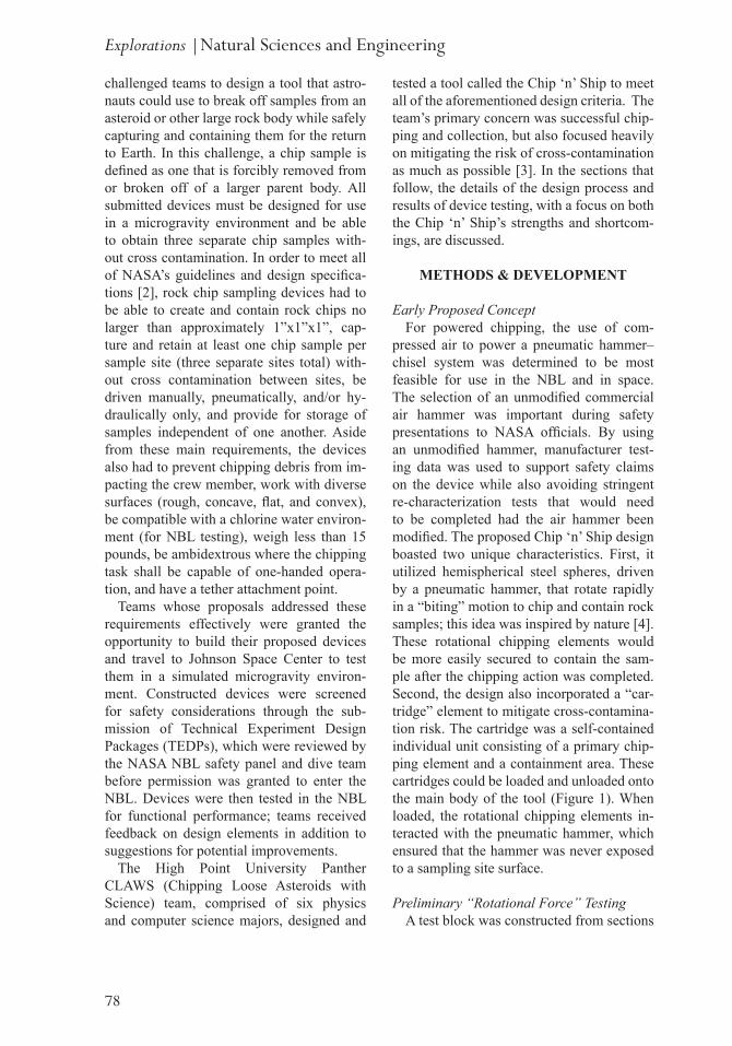
pressed air to power a pneumatic hammer–chisel system was determined to be most feasible for use in the NBL and in space. The selection of an unmodified commercial air hammer was important during safety presentations to NASA officials. By using an unmodified hammer, manufacturer test-ing data was used to support safety claims on the device while also avoiding stringent re-characterization tests that would need to be completed had the air hammer been modified. The proposed Chip ‘n’ Ship design boasted two unique characteristics. First, it utilized hemispherical steel spheres, driven by a pneumatic hammer, that rotate rapidly in a “biting” motion to chip and contain rock samples; this idea was inspired by nature [4]. These rotational chipping elements would be more easily secured to contain the sam-ple after the chipping action was completed. Second, the design also incorporated a “car-tridge” element to mitigate cross-contamina-tion risk. The cartridge was a self-contained individual unit consisting of a primary chip-ping element and a containment area. These cartridges could be loaded and unloaded onto the main body of the tool (Figure 1). When loaded, the rotational chipping elements in-teracted with the pneumatic hammer, which ensured that the hammer was never exposed to a sampling site surface.
Preliminary “Rotational Force” TestingA test block was constructed from sections
Explorations |Natural Sciences and Engineering
79
Figure 1: Cartridge (left) and main body (right). Cartridge can detach from and re-attach to main body.
of wood to hold prototype aluminum quarter spheres in place along an axle, which allowed the team to test the ability of the chipping ele-ments to chip a rock sample. Specifically, the device’s ability to translate linear motion (the driving hammer) into rotational motion (the quarter-spheres chipping) was investigated. Initial tests indicated that the prototype did not permit enough force from the driving hammer to be translated into effective force for chipping a rock sample. During this test-ing, the rings on the spheres that attached them to the axle were warped and ultimately broke due to stress. The stress point at the connection of the quarter spheres to the axle was very weak in the aluminum shells, so steel quarter-spheres were fabricated for the same functional test. While the ring through which the axle passed remained intact during the testing of the steel quarter-spheres, they were unable to chip samples from the rock. These results indicated that the use of the ro-tational system for completing the chipping action was not a feasible approach, and the design was appropriately revised.
Element Revision & Computer-Aided Design (CAD) Modeling
The initial design was modified to utilize the pneumatic hammer itself as the direct driver for the chipping action. A hardened steel chisel blade was modified by remov-ing the cutting feature and affixing a collar to the end of the chisel shaft; this modified chisel was fixed with the hammer and never removed. This “driver piston” chisel actu-ated other chipping chisel bits, which were fixed in individual cartridges using a spring and collar system. The quarter spheres were modified to act as cartridge doors to contain the sample after a successful chipping action.
Initial designs of the device consisted of a series of crude sketches with no concrete dimensions. After a final design was formu-lated, dimensions were added for drawing and the design in AutoCAD. Sections of the design were 3-D printed for functional testing before metal parts were ordered or developed. The three dimensional model highlighted weak points that needed to be revised, as well as ways to modify moving parts for optimal
Brooks, Cantor, Ickowski, Simeonides, Stidham and Vasquez Soto
80
Final Prototype DesignThe main portion of the working prototype
featured a pneumatic air hammer secured by metal collars and bolted in place inside of a section of aluminum housing. The hammer-ing action was normally activated by squeez-ing a hand trigger. However, after review-ing our TEDP, NASA officials questioned how a stuck trigger malfunction would be handled in the test environment and in space. Additionally, there was some concern that an astronaut’s bulky glove could become pinched by the lever itself during operation. To address these concerns, we elected to per-manently force a stuck trigger as part of the final design and develop a different method of controlling air flow. A ball valve was af-fixed to the air inlet on the hammer to pro-vide simple and effective user control of the air flow. A six-inch length of pneumatic pipe was affixed to the ball valve to extend the grip of the device, providing greater maneu-verability and leverage (as per the suggestion of the NBL dive team members prior to NBL testing).
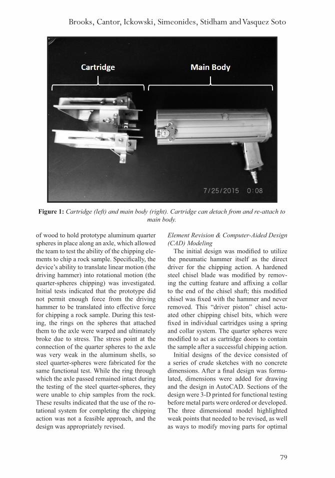
functional operation. Models and mockups of individual design components were analyzed for functional feasibility and accordingly re-vised. Building on the strengths of each suc-cessive CAD model of the Chip ‘n’ Ship, a final preliminary CAD design was developed for both the cartridge (Figure 2) and the full device (Figure 3). The lever-actuated door opening mechanism was not feasible based on functional testing, and had to be replaced with a simpler mechanism.
After this change was implemented, U-shaped aluminum pieces were attached to each cartridge to allow the user to open the cartridges by “pushing” the device into the surface to be chiseled. The doors were af-fixed to these U-shaped “legs” initially with braided wire, and were automatically closed using an interior spring system (Figure 4). After extended use, the wire became bent and would not easily return to a relaxed state, thus preventing the doors from closing prop-erly. The thread was exchanged for high-ten-sion fishing line, which retained its shape and length more consistently and predictably.
Figure 2: CAD drawing of early cartridge design. Quarter-sphere doors house the chipping element and are operated by the lever system affixed to the outside of the cartridge. The lever
system was replaced for functional purposes.
Explorations |Natural Sciences and Engineering
81
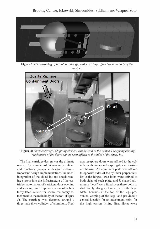
The final cartridge design was the ultimate result of a number of increasingly refined and functionally-capable design iterations. Important design implementations included: integration of the chisel bit and shock brac-ing system into the infrastructure of the car-tridge, automation of cartridge door opening and closing, and implementation of a but-terfly latch system for secure temporary at-tachment to the main body of the tool (Figure 5). The cartridge was designed around a three-inch thick cylinder of aluminum. Steel
quarter-sphere doors were affixed to the cyl-inder with hinges and a spring-loaded closing mechanism. An aluminum plate was affixed to opposite sides of the cylinder perpendicu-lar to the hinges. Two bolts were affixed to both sides of each plate, and U-shaped alu-minum “legs” were fitted over these bolts to slide freely along a channel cut in the legs. Metal brackets at the top of the legs pre-vented warping of the legs, and provided a central location for an attachment point for the high-tension fishing line. Holes were
Figure 3: CAD drawing of initial tool design, with cartridge affixed to main body of the device.
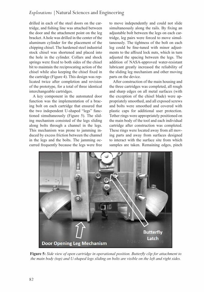
Figure 4: Open cartridge. Chipping element can be seen in the center. The spring closing mechanism of the doors can be seen affixed to the sides of the chisel bit.
Brooks, Cantor, Ickowski, Simeonides, Stidham and Vasquez Soto
82
drilled in each of the steel doors on the car-tridge, and fishing line was attached between the door and the attachment point on the leg bracket. A hole was drilled in the center of the aluminum cylinder for the placement of the chipping chisel. The hardened steel industrial stock chisel was shortened and placed into the hole in the cylinder. Collars and shock springs were fixed to both sides of the chisel bit to maintain the reciprocating action of the chisel while also keeping the chisel fixed in the cartridge (Figure 4). This design was rep-licated twice after completion and revision of the prototype, for a total of three identical interchangeable cartridges.
A key component in the automated door function was the implementation of a brac-ing bolt on each cartridge that ensured that the two independent U-shaped “legs” func-tioned simultaneously (Figure 5). The slid-ing mechanism consisted of the legs sliding along bolts through a channel in the legs. This mechanism was prone to jamming in-duced by excess friction between the channel in the legs and the bolts. The jamming oc-curred frequently because the legs were free
to move independently and could not slide simultaneously along the rails. By fixing an adjustable bolt between the legs on each car-tridge, leg pairs were forced to move simul-taneously. The tightness of the bolt on each leg could be fine-tuned with minor adjust-ments to the affixed lock nuts, which in turn adjusted the spacing between the legs. The addition of NASA-approved water-resistant lubricant greatly increased the reliability of the sliding leg mechanism and other moving parts on the device.
After construction of the main housing and the three cartridges was completed, all rough and sharp edges on all metal surfaces (with the exception of the chisel blade) were ap-propriately smoothed, and all exposed screws and bolts were smoothed and covered with plastic caps for additional user protection. Tether rings were appropriately positioned on the main body of the tool and each individual cartridge after construction was completed. These rings were located away from all mov-ing parts and away from surfaces designed to interact with the surface site from which samples are taken. Remaining edges, pinch
Figure 5: Side view of open cartridge in operational position. Butterfly clip for attachment to the main body (top) and U-shaped legs sliding on bolts are visible on the left and right sides.
Explorations |Natural Sciences and Engineering
83
the LoggerPro data analysis software. Data recording started at the initial applied force from the user before oscillations began.
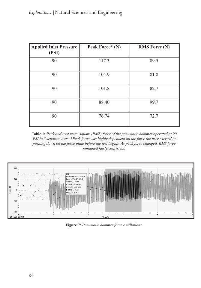
Hammer Force Plate TestApplied inlet air pressure of 90 PSI (Table
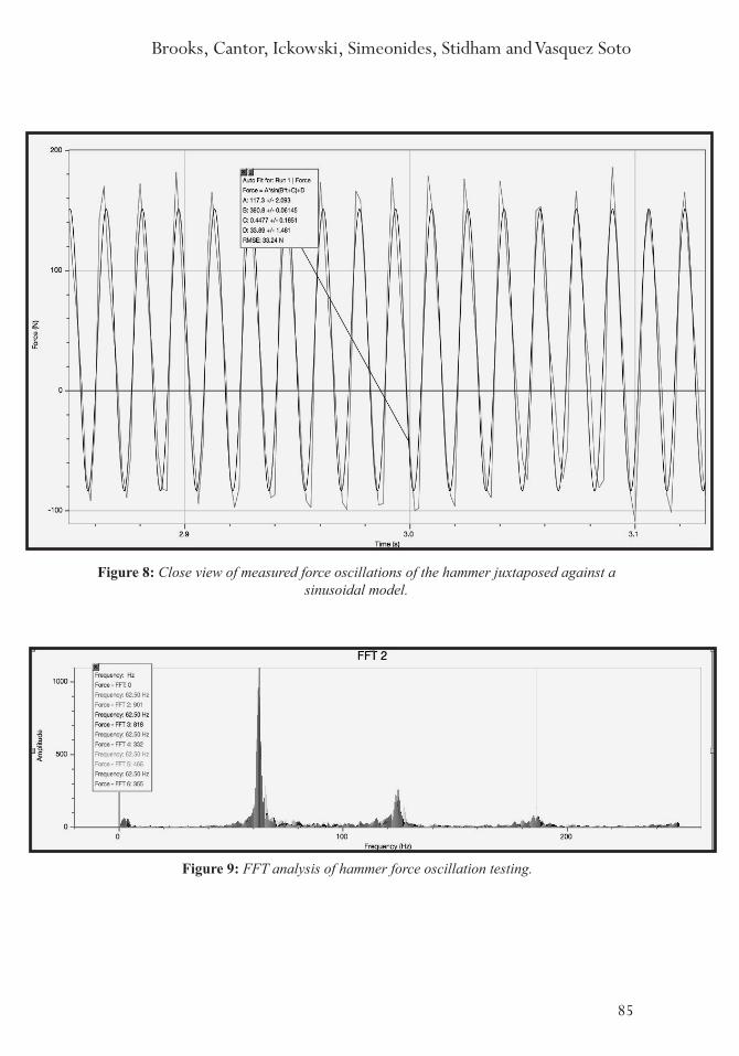
1) was used to measure peak force and root mean square force over a brief actuation pe-riod (Figure 7). Frequency and amplitude of force oscillations were analyzed, and a sim-ple sinusoidal curve was fitted to the data to provide a rough model of hammer operation (Figure 8). The simple curve fit provided an excellent model over short time frames, but the oscillatory behavior observed in the ap-plied force was more accurately described as a superposition of multiple sinusoids with different amplitudes and frequencies. Fast Fourier Transform (FFT) analysis was per-formed to determine peak frequencies of os-cillation, with the principal peak frequency being approximately 62 Hz (Figure 9). The focus was the peak frequency, so harmonics were not investigated further.
Chisel Force Plate TestApplied inlet air pressure of 90 PSI (Table
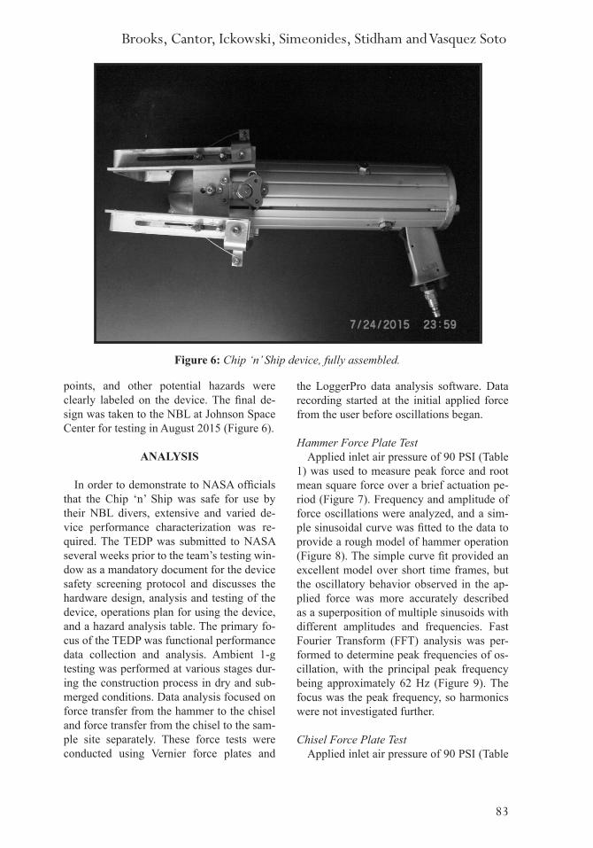
points, and other potential hazards were clearly labeled on the device. The final de-sign was taken to the NBL at Johnson Space Center for testing in August 2015 (Figure 6).
ANALYSIS
In order to demonstrate to NASA officials that the Chip ‘n’ Ship was safe for use by their NBL divers, extensive and varied de-vice performance characterization was re-quired. The TEDP was submitted to NASA several weeks prior to the team’s testing win-dow as a mandatory document for the device safety screening protocol and discusses the hardware design, analysis and testing of the device, operations plan for using the device, and a hazard analysis table. The primary fo-cus of the TEDP was functional performance data collection and analysis. Ambient 1-g testing was performed at various stages dur-ing the construction process in dry and sub-merged conditions. Data analysis focused on force transfer from the hammer to the chisel and force transfer from the chisel to the sam-ple site separately. These force tests were conducted using Vernier force plates and
Figure 6: Chip ‘n’ Ship device, fully assembled.
Brooks, Cantor, Ickowski, Simeonides, Stidham and Vasquez Soto
84
Figure 7: Pneumatic hammer force oscillations.
Applied Inlet Pressure (PSI)
Peak Force* (N) RMS Force (N)
90 117.3 89.5
90 104.9 81.8
90 101.8 82.7
90 88.40 99.7
90 76.74 72.7
Table 1: Peak and root mean square (RMS) force of the pneumatic hammer operated at 90 PSI in 5 separate tests. *Peak force was highly dependent on the force the user exerted in pushing down on the force plate before the test begins. As peak force changed, RMS force
remained fairly consistent.
Explorations |Natural Sciences and Engineering
85
Figure 8: Close view of measured force oscillations of the hammer juxtaposed against a sinusoidal model.
Figure 9: FFT analysis of hammer force oscillation testing.
Brooks, Cantor, Ickowski, Simeonides, Stidham and Vasquez Soto
86
NBL Acoustic TestingThe final preliminary test was an acoustic
test before the device could be approved for underwater use in the NBL by NASA div-ers. The Chip ‘n’ Ship was lowered into the water and activated by a certified NBL diver, while another diver held a decibel sensor 3 feet away from the device. The sound inten-sity limit for operation in the pool was 50 dB; if the device exceeded this limit, it would not be allowed into the water as it could cause damage to other equipment or could cause hearing damage to the divers. The difference in sound intensity in water compared to air is approximately 61.5 dB, meaning that the un-derwater limit of 50 dB underwater equates to around 121.5 dB in air [5]. The Chip ‘n’ Ship operated in the range of 30-40 dB un-derwater, hitting the benchmark for other pneumatic devices that the engineers have al-lowed into the pool in the past.
RESULTS FROM NASA NEUTRAL BUOYANCY LAB TESTING
After NASA officials confirmed that the Chip ‘n’ Ship met all safety requirements, the Panther CLAWS team was offered a thirty minute time slot to test the device’s functionality in the NBL with the assistance of the facility’s dive team. During this time, the team was free to lead the divers through a series of varied functional tests performed in the simulated microgravity environment. The team briefed the divers on the opera-tion of the Chip ‘n’ Ship poolside, and then the NBL dive team executed underwater
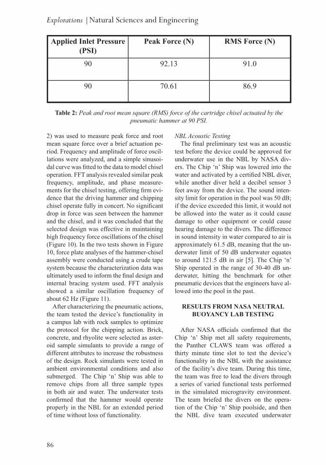
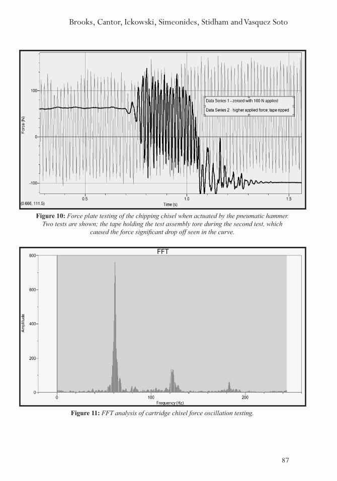
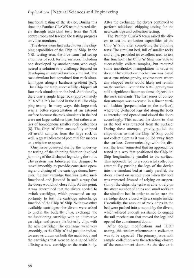
2) was used to measure peak force and root mean square force over a brief actuation pe-riod. Frequency and amplitude of force oscil-lations were analyzed, and a simple sinusoi-dal curve was fitted to the data to model chisel operation. FFT analysis revealed similar peak frequency, amplitude, and phase measure-ments for the chisel testing, offering firm evi-dence that the driving hammer and chipping chisel operate fully in concert. No significant drop in force was seen between the hammer and the chisel, and it was concluded that the selected design was effective in maintaining high frequency force oscillations of the chisel (Figure 10). In the two tests shown in Figure 10, force plate analyses of the hammer-chisel assembly were conducted using a crude tape system because the characterization data was ultimately used to inform the final design and internal bracing system used. FFT analysis showed a similar oscillation frequency of about 62 Hz (Figure 11).
After characterizing the pneumatic actions, the team tested the device’s functionality in a campus lab with rock samples to optimize the protocol for the chipping action. Brick, concrete, and rhyolite were selected as aster-oid sample simulants to provide a range of different attributes to increase the robustness of the design. Rock simulants were tested in ambient environmental conditions and also submerged. The Chip ‘n’ Ship was able to remove chips from all three sample types in both air and water. The underwater tests confirmed that the hammer would operate properly in the NBL for an extended period of time without loss of functionality.
Explorations |Natural Sciences and Engineering
Applied Inlet Pressure (PSI)
Peak Force (N) RMS Force (N)
90 92.13 91.0
90 70.61 86.9
Table 2: Peak and root mean square (RMS) force of the cartridge chisel actuated by the pneumatic hammer at 90 PSI.
87
Figure 10: Force plate testing of the chipping chisel when actuated by the pneumatic hammer. Two tests are shown; the tape holding the test assembly tore during the second test, which
caused the force significant drop off seen in the curve.
Figure 11: FFT analysis of cartridge chisel force oscillation testing.
Brooks, Cantor, Ickowski, Simeonides, Stidham and Vasquez Soto
88
After the exchange, the divers continued to perform additional chipping testing for the new cartridge and collection testing.
The Panther CLAWS team asked the div-ers to test the collection capabilities of the Chip ‘n’ Ship after completing the chipping tests. The simulant bed, full of smaller rocks and chips, provided an excellent area to test this function. The Chip ‘n’ Ship was able to successfully collect samples, but required some unorthodox manipulation in order to do so. The collection mechanism was based on a true micro-gravity environment where any chipped rocks would likely not remain on the surface. Even in the NBL, gravity was still a significant factor on dense objects like the rock simulants. The first series of collec-tion attempts was executed in a linear verti-cal fashion (perpendicular to the surface), where the U-shaped legs slid along the bolts as intended and opened and closed the doors accordingly. This caused the doors to shut as the tool was retracted from the surface. During these attempts, gravity pulled the chips down so that the Chip ‘n’ Ship could not collect them as it was pulled away from the surface. Communicating with the div-ers, the team suggested that an approach be tested in a way that positioned the Chip ‘n’ Ship longitudinally parallel to the surface. This approach led to a successful collection attempt. By pushing the legs of the device into the simulant bed at nearly parallel, the doors closed on sample even when the tool was retracted. Instead of relying on suspen-sion of the chips, the test was able to rely on the sheer number of chips and small rocks in the simulant bed in order to make sure the cartridge doors closed with a sample inside. Essentially, the amount of rock chips in the bed were pushed into a mound by the divers, which offered enough resistance to engage the rail mechanism that moved the legs and opened the containment doors.
After design modifications and TEDP testing, this underperformance in collection was to be expected. The primary issue with sample collection was the retracting closure of the containment doors. As the device is
functional testing of the device. During this time, the Panther CLAWS team directed div-ers through individual tests from the NBL control room and tracked the testing progress on video monitors.
The divers were first asked to test the chip-ping capabilities of the Chip ‘n’ Ship. In the NBL testing area, the dive team had set up a number of rock testing surfaces, including one developed by another team who engi-neered a solution to a challenge focused on developing an asteroid surface simulant. The rock simulant bed contained four rock simu-lant types along a hardness gradient [6,7]. The Chip ‘n’ Ship successfully chipped all four rock simulants in the bed. Additionally, there was a single large rock (approximately 9” X 9” X 9”) included in the NBL for chip-ping testing. In many ways, this large rock was a better representation of an asteroid surface because the rock simulants in the bed were not large, solid surfaces, but rather a se-ries of homogenous smaller rock collections [8]. The Chip ‘n’ Ship successfully chipped off useful samples from the large rock as well, a great indicator of potential for success on a mission to space.
One issue observed during the underwa-ter testing of the chipping function involved jamming of the U-shaped legs along the bolts. The system was lubricated and designed to move smoothly to provide consistent open-ing and closing of the cartridge doors; how-ever, the first cartridge that was tested mal-functioned and jammed in such a way that the doors would not close fully. At this point, it was determined that the divers needed to switch cartridges, which presented an op-portunity to test the cartridge interchange function of the Chip ‘n’ Ship. With two other available cartridges, the divers were asked to unclip the butterfly clips, exchange the malfunctioning cartridge with an alternative cartridge, and secure the butterfly clips with the new cartridge. The exchange went very smoothly, as the Chip ‘n’ had position indica-tor arrows drawn on both the main body and the cartridges that were to be aligned while affixing a new cartridge to the main body.
Explorations |Natural Sciences and Engineering
89
asteroids.There are several design elements of the
Chip ‘n’ Ship that could be significantly im-proved. Independent opening and closing of each of the two quarter-sphere contain-ment doors on each cartridge would allow for a greater range of operational angles and would improve sample collection success rate. Additionally, a more robust solution to the door actuation element should be in-vestigated. Using high tension fishing line has proven to be successful, but risks fray-ing and breaking with extended exposure to rock shards. One possible solution to such a problem is a mechanical metal arm that is rigid and will not stretch or fray, positioned where it will not risk being bent or otherwise damaged. A more effective method of ensur-ing that the doors of each cartridge remain secured after sample collection would be an improvement as well. A magnetic locking system and a simple latch system are both potential candidates for such a modification.
Additionally, operating the Chip ‘n’ Ship in a true micro-gravity environment would likely lead to better performance. Rock chips would not immediately fall back to the sur-face, and the retractable collection method would have a more consistent success rate. The Chip ‘n’ Ship significantly reduces the effort from the operator in order to achieve a successful sample collection. Even for a lunar mission, the acceleration due to grav-ity is roughly one sixth of the acceleration on Earth. In a microgravity environment, the acceleration due to gravity is even lower. However, the test in the NBL was useful for confirming the functionality of the chipping action and the usability of the device in terms of ergonomics and weight.
CONCLUSION
In response to NASA’s Micro-g NExT program challenge, a team of High Point University physics majors designed and constructed a handheld device called the Chip ‘n’ Ship for chipping off and collect-ing surface samples from asteroids and other
retracted from a surface, the doors close au-tomatically as a response. In an environment with gravitational forces present, rock chips do not remain suspended in space and fall quickly back to the sample surface. In a true micro-gravity environment, these rock chips would fall back to the surface more slowly, increasing the effectiveness of the retracting capture method. The divers offered a similar assessment, stating that the design was clever and easy to use, and that the collection issue would not be present if the device were op-erated in a true micro-gravity environment, such as the surface of an asteroid. Most im-portantly, the device was able to chip off rock samples from different sites without cross contamination.
The test divers and NASA officials deemed the testing experience of the Chip ‘n’ Ship in the Neutral Buoyancy Lab to be highly suc-cessful. The chipping action was successful on various rock and rock simulant surfaces. The design was highly ergonomic, and the dive team complimented the user-friendliness of the device. Tether point selection played a significant role in maximizing maneuverabil-ity while minimizing risk of entanglement with tether lines.
DISCUSSION
The NBL divers gave the Panther CLAWS team positive feedback regarding the handling and operation of the Chip ‘n’ Ship. During post-testing presentations and reviews, NASA officials from the Extravehicular Activity (EVA) team closely examined the design. The interchangeable self-contained cartridges and automated door mechanisms were both popular design elements. The EVA team will consider the design moving for-ward in preparation for future missions, and perhaps incorporate elements of the Chip ‘n’ Ship design into the final design of their EVA rock chip sampling tool. The team’s work on the Chip ‘n’ Ship could potentially influence NASA engineers and ultimately contribute to the success of future missions, includ-ing an eventual manned mission to Mars or
Brooks, Cantor, Ickowski, Simeonides, Stidham and Vasquez Soto
90
to further improve upon the Chip ‘n’ Ship design, with a focus on the problems associ-ated with the collection performance. Some of the team members have graduated and are no longer available to help hands-on with project modifications. However, the testing at NASA generated a significant amount of interest in the department, so it is likely that a new team will come together in the future and may choose to modify and improve the Chip ‘n’ Ship as their project. Until then, NASA will use concepts from the Chip ‘n; Ship, along with other designs submitted to the Micro-g NExT program, to develop us-able EVA tools for astronauts to deploy on future space missions.
microgravity bodies. Divers at NASA’s Neutral Buoyancy Lab facility at Johnson Space Center tested the device on several as-teroid simulant surfaces and were able to dis-lodge samples with ease. Containment of the samples proved a bit more challenging, pri-marily due to the persisting effects of gravity in the NBL which would be much less of a problem in a true micro-gravity environ-ment. Overall, NASA officials and the NBL divers deemed the Chip ‘n’ Ship a success and praised the device for its unique design characteristics.
The practical skills the Panther CLAWS team acquired through the development and construction of the device will be helpful in further instrument design and testing. In the future, a new student team will be assembled
ACKNOWLEDGEMENTS
• Mr. Eric Scarlett, for many hours of prototype development and creative, practical engi-neering insight.
• Mr. Jeremy Allen, for assistance in the use of his metal-shaping facility during construction.
• The High Point University Physics Department for their collective support of this project.• The High Point University Student Government Association, for funding construction of
the Chip ‘n’ Ship and travel to Johnson Space Center.• Dr. Nido Qubein for supporting this endeavor.• NASA, for the opportunity to participate in the Micro-g NExT initiative.
Explorations |Natural Sciences and Engineering
91
REFERENCES
[1] Cheng, A. F., Pieters, C. M., & Murchie, S. L. 1996. Sample Collection from Planetary Surfaces. Lunar and Planetary Science. 27: 213-214.
[2] “NASA Microgravity University,” https://microgravityuniversity.jsc.nasa.gov, National Aeronautics and Space Administration, 1 Jan. 2015. Web. 25 Jan 2015.
[3] Brownlee, D. E. 1985. Cosmic Dust: Collection and Research. Ann. Rev. Earth Planet. Sci. 13: 147-173.
[4] Herrel, A., O’Reilly J. C., & Richmond, A. M. 2002. Evolution of bite performance in turtles. Journal of Evolutionary Biology. 15 (6): 1083-1094.
[5] Finfer, D. C., Leighton, T. G., and White, P. R. 2008. Issues relating to the use of a 61.5 dB conversion factor when comparing airborne and underwater anthroprogenic noise levels. Applied Acoustics. 69: 464-471.
[6] Howell, E. S. 1995. Probing asteroid composition using visible and near-infrared spectros copy. Thesis (Ph.D.). University of Arizona. Dissertation Abstracts International, 57 / (02): 0957, Section: B.
[7] Ostro, S. J., et al. 1991. Asteroid 1986 DA: Radar Evidence for a Metallic Composition. Science. 252 (5011): 1399-1404.
[8] Gaffey, Michael J., et al. 1993. Mineralogical Variations within the S-Type Asteroid Class. Icarus. 106 (2): 573-602.
Brooks, Cantor, Ickowski, Simeonides, Stidham and Vasquez Soto