1 The Cryogenic Propellant Storage and Transfer Technology Demonstration Mission: Progress and Transition Michael L. Meyer William J. Taylor Carol A. Ginty Matthew E. Melis NASA Glenn Research Center July 28, 2014 AIAA Propulsion and Energy Forum 1 Approved for Public Release https://ntrs.nasa.gov/search.jsp?R=20140017303 2018-06-25T20:31:23+00:00Z
Transcript
1
The Cryogenic Propellant Storage and Transfer Technology Demonstration Mission: Progress
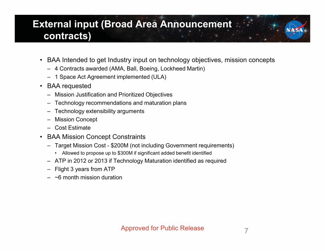
• BAA Mission Concept Constraints– Target Mission Cost - $200M (not including Government requirements)
• Allowed to propose up to $300M if significant added benefit identified– ATP in 2012 or 2013 if Technology Maturation identified as required– Flight 3 years from ATP– ~6 month mission duration
Approved for Public Release
8
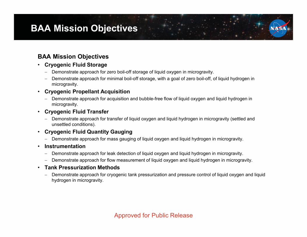
BAA Mission Objectives
BAA Mission Objectives• Cryogenic Fluid Storage
� Demonstrate approach for zero boil-off storage of liquid oxygen in microgravity.� Demonstrate approach for minimal boil-off storage, with a goal of zero boil-off, of liquid hydrogen in
microgravity.• Cryogenic Propellant Acquisition
� Demonstrate approach for acquisition and bubble-free flow of liquid oxygen and liquid hydrogen in microgravity.
• Cryogenic Fluid Transfer� Demonstrate approach for transfer of liquid oxygen and liquid hydrogen in microgravity (settled and
� Demonstrate approach for mass gauging of liquid oxygen and liquid hydrogen in microgravity.• Instrumentation
� Demonstrate approach for leak detection of liquid oxygen and liquid hydrogen in microgravity.� Demonstrate approach for flow measurement of liquid oxygen and liquid hydrogen in microgravity.
• Tank Pressurization Methods� Demonstrate approach for cryogenic tank pressurization and pressure control of liquid oxygen and liquid
hydrogen in microgravity.
Approved for Public Release
9
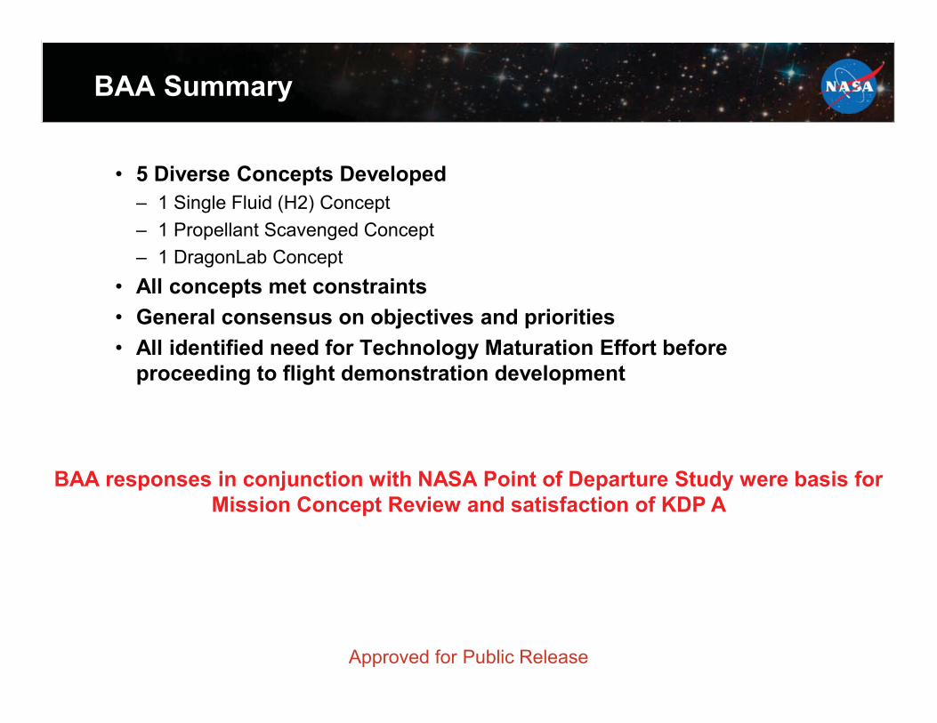
BAA Summary
• 5 Diverse Concepts Developed– 1 Single Fluid (H2) Concept– 1 Propellant Scavenged Concept– 1 DragonLab Concept
• All concepts met constraints• General consensus on objectives and priorities• All identified need for Technology Maturation Effort before
proceeding to flight demonstration development
BAA responses in conjunction with NASA Point of Departure Study were basis for Mission Concept Review and satisfaction of KDP A
Approved for Public Release
10
SRR/MDR Concept
• CPST Project successfully conducted an SRR / MDR in September of 2013
• Concept was based on study of DragonLab mission identified in the reformulation studies
• Based on SRR/MDR results, CPST project proceeded toKDP B in December of 2013
Approved for Public Release
11
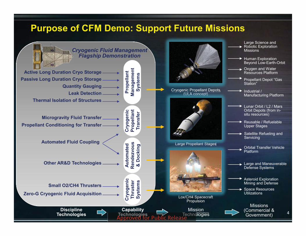
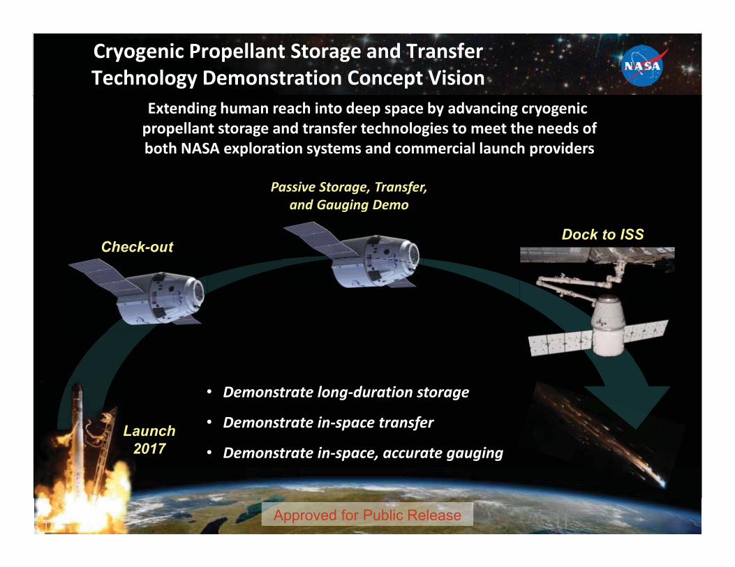
Extending human reach into deep space by advancing cryogenic propellant storage and transfer technologies to meet the needs of both NASA exploration systems and commercial launch providers
Cryogenic Propellant Storage and Transfer Technology Demonstration Concept Vision
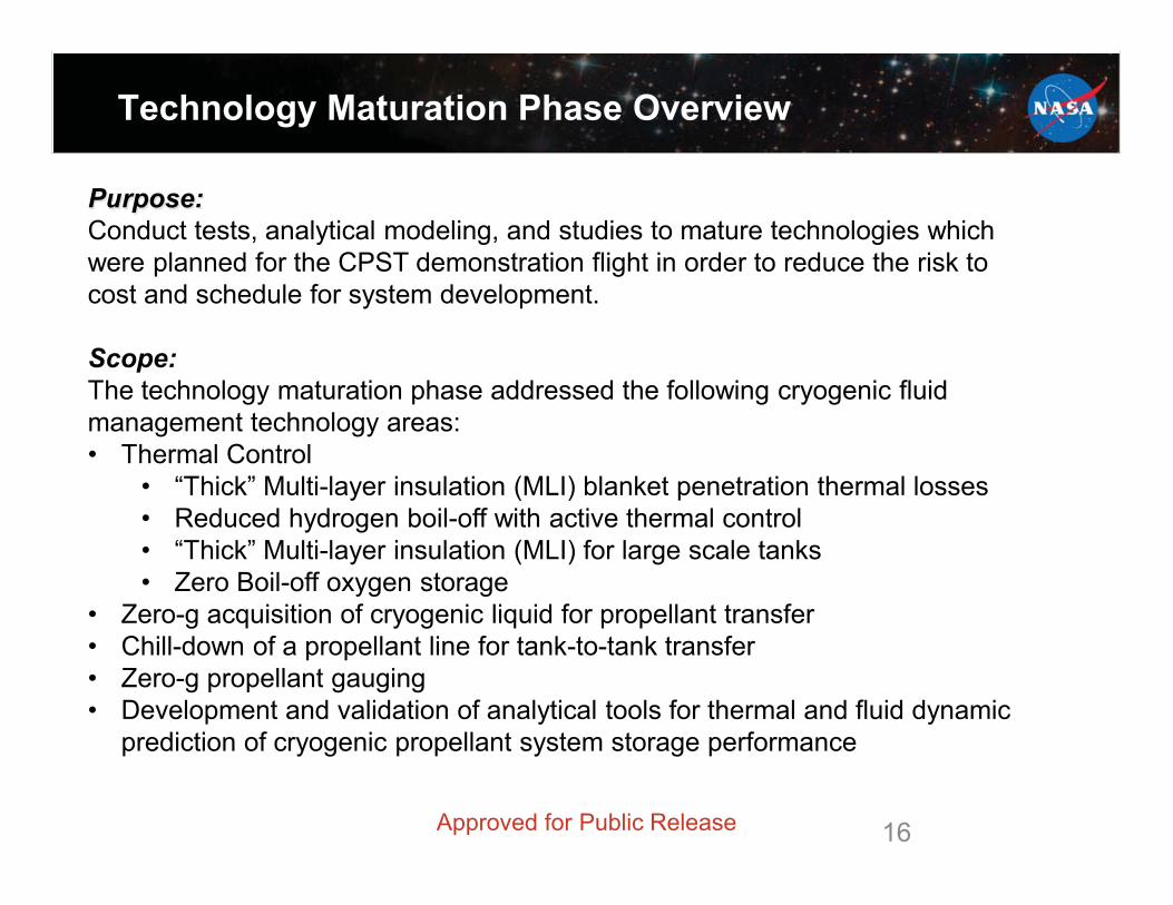
Purpose:Conduct tests, analytical modeling, and studies to mature technologies which were planned for the CPST demonstration flight in order to reduce the risk to cost and schedule for system development.
Scope:The technology maturation phase addressed the following cryogenic fluid management technology areas:• Thermal Control
• “Thick” Multi-layer insulation (MLI) blanket penetration thermal losses• Reduced hydrogen boil-off with active thermal control• “Thick” Multi-layer insulation (MLI) for large scale tanks• Zero Boil-off oxygen storage
• Zero-g acquisition of cryogenic liquid for propellant transfer• Chill-down of a propellant line for tank-to-tank transfer• Zero-g propellant gauging• Development and validation of analytical tools for thermal and fluid dynamic
prediction of cryogenic propellant system storage performance
Approved for Public Release
17
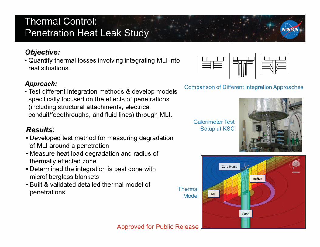
Thermal Control: Penetration Heat Leak Study
Objective:• Quantify thermal losses involving integrating MLI into
real situations.
Approach:• Test different integration methods & develop models
specifically focused on the effects of penetrations (including structural attachments, electrical conduit/feedthroughs, and fluid lines) through MLI.
Results:• Developed test method for measuring degradation
of MLI around a penetration• Measure heat load degradation and radius of
thermally effected zone• Determined the integration is best done with
microfiberglass blankets• Built & validated detailed thermal model of
penetrations Thermal Model
Comparison of Different Integration Approaches
Approved for Public Release
Buffer
MLI
Strut
Cold Mass
Calorimeter Test Setup at KSC
18
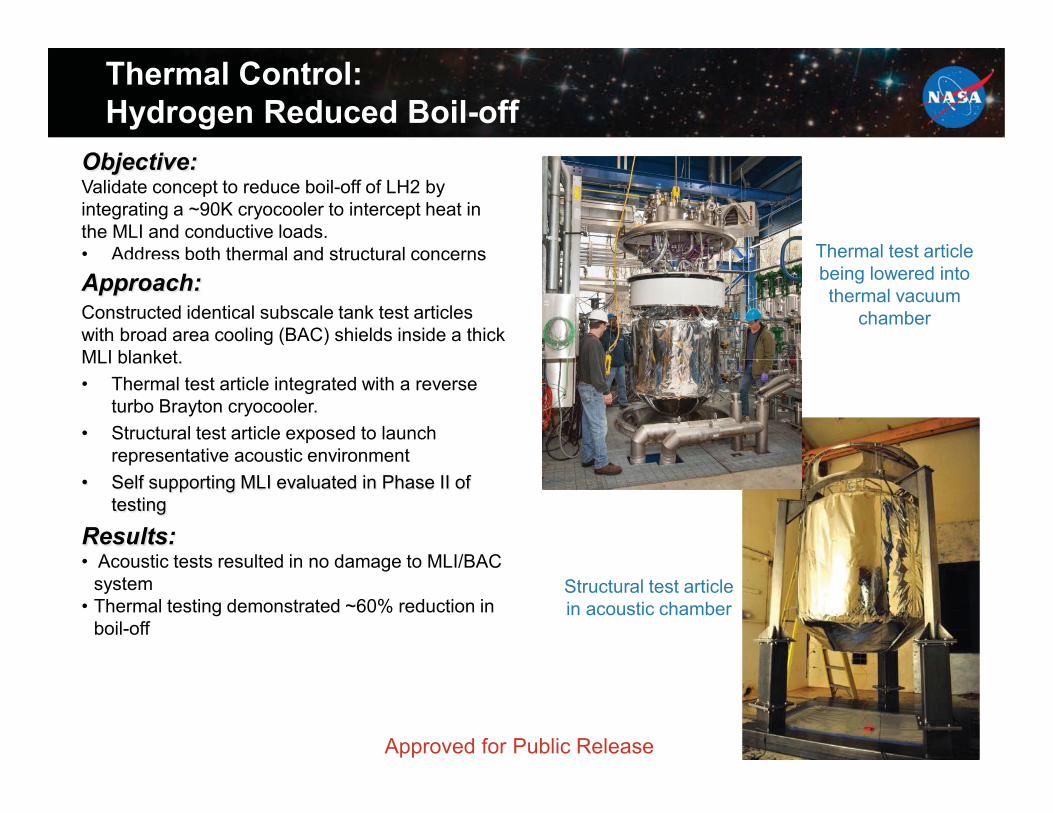
Objective:Validate concept to reduce boil-off of LH2 by integrating a ~90K cryocooler to intercept heat in the MLI and conductive loads.• Address both thermal and structural concernsAddress bothh bothApproach:Constructed identical subscale tank test articles with broad area cooling (BAC) shields inside a thick MLI blanket. • Thermal test article integrated with a reverse
turbo Brayton cryocooler.• Structural test article exposed to launch
representative acoustic environment• Self supporting MLI evaluated in Phase II of
testing
Results:• Acoustic tests resulted in no damage to MLI/BAC
system• Thermal testing demonstrated ~60% reduction in
boil-off
Completed Test Article
Thermal Control: Hydrogen Reduced Boil-off
Approved for Public Release
Thermal test article being lowered into thermal vacuum
chamber
Structural test article in acoustic chamber
19
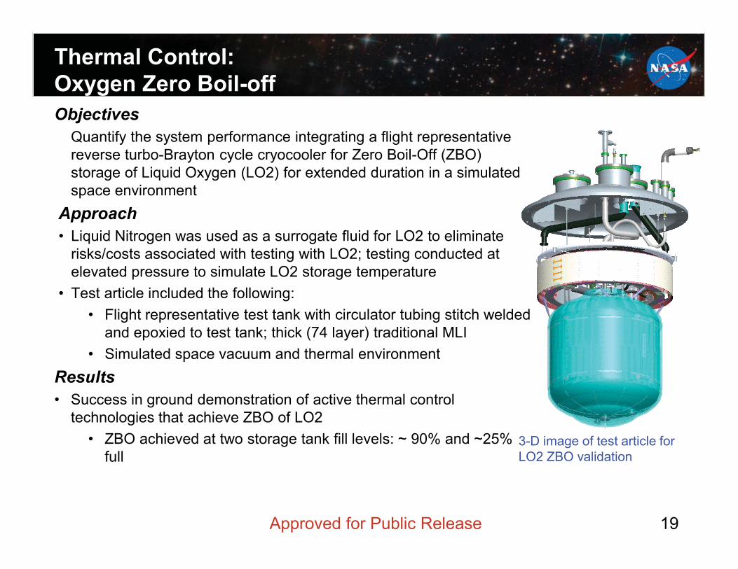
Thermal Control: Oxygen Zero Boil-offObjectives
Quantify the system performance integrating a flight representative reverse turbo-Brayton cycle cryocooler for Zero Boil-Off (ZBO) storage of Liquid Oxygen (LO2) for extended duration in a simulated space environment
Approach• Liquid Nitrogen was used as a surrogate fluid for LO2 to eliminate
risks/costs associated with testing with LO2; testing conducted at elevated pressure to simulate LO2 storage temperature
• Test article included the following:• Flight representative test tank with circulator tubing stitch welded
and epoxied to test tank; thick (74 layer) traditional MLI• Simulated space vacuum and thermal environment
Results• Success in ground demonstration of active thermal control
technologies that achieve ZBO of LO2• ZBO achieved at two storage tank fill levels: ~ 90% and ~25%
full3-D image of test article for LO2 ZBO validation
Approved for Public Release 19
20
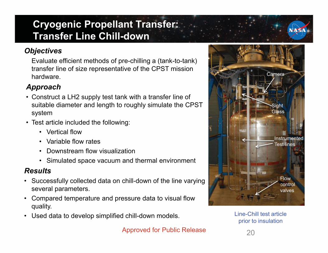
Cryogenic Propellant Transfer: Transfer Line Chill-down
20
ObjectivesEvaluate efficient methods of pre-chilling a (tank-to-tank) transfer line of size representative of the CPST mission hardware.
Approach• Construct a LH2 supply test tank with a transfer line of
suitable diameter and length to roughly simulate the CPST system
• Test article included the following:• Vertical flow• Variable flow rates• Downstream flow visualization• Simulated space vacuum and thermal environment
Results• Successfully collected data on chill-down of the line varying
several parameters.• Compared temperature and pressure data to visual flow
quality.• Used data to develop simplified chill-down models. Line-Chill test article
prior to insulation
Instrumented Test lines
Camera
Flow control valves
Sight GlassSSSSSSSSSS
InTTT
Ca
cv
Approved for Public Release
21
LH2 Gas to Droplet
LH2 Wavy Annular Flow
LH2 Bubbly Flow
Propellant Transfer: Transfer line Chill-down Visualization
LLHH GGGas tto DDropllett
LH W A l Fl
LH B bbl Flo
Approved for Public Release
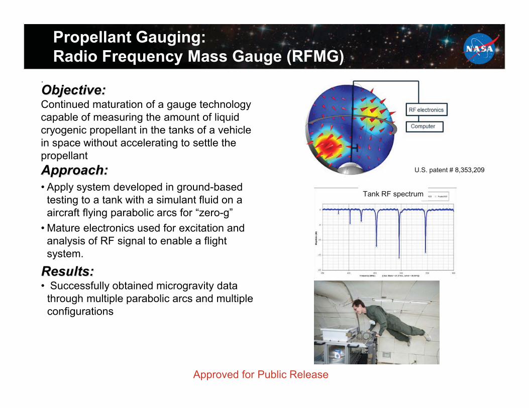
22
..Objective:Continued maturation of a gauge technology capable of measuring the amount of liquid cryogenic propellant in the tanks of a vehicle in space without accelerating to settle the propellantApproach:• Apply system developed in ground-based
testing to a tank with a simulant fluid on a aircraft flying parabolic arcs for “zero-g”
• Mature electronics used for excitation and analysis of RF signal to enable a flight system.
Results:• Successfully obtained microgravity data
through multiple parabolic arcs and multiple configurations
Completed Test Article
Propellant Gauging:Radio Frequency Mass Gauge (RFMG)
Approved for Public Release
U.S. patent # 8,353,209
Tank RF spectrum
232
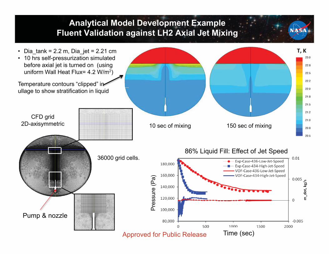
86% Liquid Fill: Effect of Jet Speed
Analytical Model Development ExampleFluent Validation against LH2 Axial Jet Mixing
before axial jet is turned on (using uniform Wall Heat Flux= 4.2 W/m2)
Temperature contours “clipped” in ullage to show stratification in liquid
Pump & nozzle
10 sec of mixing 150 sec of mixing
Time (sec)
W/m2)
n
Pre
ssur
e (P
a)
CFD grid 2D-axisymmetric
36000 grid cells.
Approved for Public Release
24
Summary
24
• The Cryogenic Propellant Storage and Transfer Technology Demonstration mission is being reformulated into a ground test activity.
• The Technology Maturation Phase of the mission was highly successful in raising the maturity of key technologies to reduce the risk of developing these systems for a flight demonstration. Advancements were made in:• Thermal control• Propellant transfer• Propellant gauging
• In addition, advancements were incorporated into NASA’s analytical modeling for cryogenic fluid management systems.