Page 1
Calhoun: The NPS Institutional Archive
Theses and Dissertations Thesis Collection
1991-06
The development of a model builder for a
microcircuit substrate
Roesch, Patric Karl
Monterey, California. Naval Postgraduate School
http://hdl.handle.net/10945/26479
Page 6
NAVAL POSTGRADUATE SCHOOL
Monterey, California
THESIS
THE DEVELOPMENT OF A MODELBUILDER FOR A MICROCIRCUIT
SUBSTRATE
by
Patric Karl Roesch
June 1991
Thesis Advisor: A.D. Kraus
Approved for public release; distribution unlimited.
T256342
Page 8
UnclassifiedSecurity Classification of this page
REPORT DOCUMENTATION PAGEla Report Security Classification
Unclassified
lb Restrictive Markings
2a Security Classification Authority
2b Declassification/Downgrading Schedule
3 Distribution Availability of Report
Approved for public release; distribution is unlimited.
4 Performing Organization Report Number(s) 5 Monitoring Organization Report Number(s)
6a Name of Performing Organization
Naval Postgraduate School6b Office Symbol
(If Applicable) 327a Name of Monitoring Organization
Naval Postgraduate School
6c Address (city, state, and ZIP code)
Monterey, CA 93943-50007 b Address (city, state, and ZIP code)
Monterey, CA 93943-5000
5a Name of Funding/Sponsoring Organization 8b Office Symbol
(7/ Applicable)
9 Procurement Instrument Identification Number
8c Address (city, state, and ZIP code) 1 Source of Funding Numbers
Program Element Number Project No Task No Work Unit Accession No
li Title (include Security Classification) THE DEVELOPMENT OF A MODEL BUILDER FOR A MICROCIRCUITSUBSTRATE
12 Personal Author(s) Patric K. Roesch
13a Type of Report
Master's Thesis13b Time Covered
From
14 Date of Report (year, month,day)
1991 , May 7
1 5 Page Count
101
16 Supplementary Notation The views expressed in this thesis are those of the author and do not reflect the official
policy or position of the Department of Defense or the U.S. Government.
17 Cosati Codes
Field Group Subgroup
1 8 Subject Terms (continue on reverse if necessary and identify by block number)
Model Builder; Development; Microcircuit; Substrate
1 9 Abstract (continue on reverse if necessary and identify by block number
The Naval Postgraduate School is currently in possession of software designed to perform a thermal
analysis of electronic components. This software package incorporates a model builder whose primary function
is to generate a thermal model. In its present configuration, the model builder requires an inordinate amount of
time for data input and model verification. This thesis describes the development of a model builder designed
specifically to reduce the time required to model the substrate, epoxy, and carrier layers of a microcircuit
assembly.
20 Distribution/Availability of Abstract
|X| unclassified/unlimited same as report
JDTIC users
21 Abstract Security Classification
Unclassified
22a Name of Responsible Individual
Allan D. Kraus22b Telephone (Include Area code)
(408) 646-273022c Office Symbol
EC/KSDD FORM 1473, 84 MAR 83 APR edition may be used until exhausted
All other editions are obsolete
security classification of this page
Unclassified
Page 9
Approved for public release; distribution is unlimited.
The Development of a Model Builder for a
Microcircuit Substrate
by
Patric K. Roesch
Lieutenant, United States Navy
B.S., University of Florida, 1982
Submitted in partial fulfillment of the
requirements for the degree of
MASTER OF SCIENCE IN ELECTRICAL ENGINEERING
from the
NAVAL POSTGRADUATE SCHOOLJune 1991
Michael A. Morgan, Chairman, Department of Electrical and
Computer Engineering
Page 10
ABSTRACT
The Naval Postgraduate School is currently in possession
of software designed to perform a thermal analysis of
electronic components. This software package incorporates a
model builder which contains two programs whose primary
function is to generate a thermal model. In its present
configuration, the model builder reguires an inordinate amount
of time for data input and model verification. This thesis
describes the development of a model builder designed
specifically to reduce the time reguired to model the
substrate, epoxy and carrier layers of a microcircuit assembly.
111
Page 11
TABLE OF CONTENTS
I . INTRODUCTION 1
II
.
THE REASON FOR THERMAL ANALYSIS 5
A. RELIABILITY 6
B
.
MATERIAL SELECTION 9
C. BIAS STABILIZATION 11
1. Operating in the Forward Bias Region 13
D. CATASTROPHIC THERMAL FAILURE 14
III
.
HEAT TRANSFER 17
A
.
CONDUCTION 17
1. General Equation of Heat Conduction 18
2 . Simple Plane Slab 20
3 . Electrothermal Analog 22
B
.
CONVECTION 2 3
1 . Electrothermal Analog 2 5
C. RADIATION 27
1. Transformation of the General Radiation
Equation 29
2. General Problems of Heat Transfer by
Radiation 32
IV. FINITE DIFFERENCES 33
A . FUNDAMENTAL CONCEPTS 3 3
1. First Derivative Approximation 34
2 . Second Derivative Approximation 36
iv
Page 12
00*
B. NODE ANALYSIS 3 7
V. THE MODEL BUILDER 4 3
A. THE THERMAL ANALYZER INPUT DATA FILE 4 3
B. FEATURES 48
APPENDIX A - TMDL LISTING 51
LIST OF REFERENCES 9 3
INITIAL DISTRIBUTION LIST 94
Page 14
I. INTRODUCTION
The Naval Postgraduate School is currently in possession
of software designed to perform a thermal analysis of
electronic components. This software package incorporates a
model builder which contains two programs whose primary
function is to generate a thermal model, or input data file,
to be read by the thermal analyzer program. The first program
is considered to be a general model builder which is used in
all model development stages as well as to modify an existing
model. The second alternative was developed to generate a
thermal model of a specific microcircuit geometry.
The development of an accurate thermal model of an
electrical component reguires that the structure be subdivided
into a large number of small but finite subvolumes. Each
subvolume is assumed to be isothermal with the centroids, also
called nodes, considered to be representative of the entire
subvolume. The most difficult problem encountered in the
development of a thermal model is the generation of n-node
equations in ^-unknown temperatures where the nodes are
connected by thermal conductances. As the desired accuracy of
the thermal model increases, the number of required node
equations becomes extremely large. Therefore, it is imperative
Page 15
that the design engineer have access to a model builder that
will produce the thermal model in a reasonable period of time.
In its present configuration, the thermal analysis
software contains a model builder that generates the required
node equations automatically. There is no question that the
existing model builder programs have replaced the extremely
laborious and time consuming process of generating the node
equations by hand. However, they still require an inordinate
amount of time for data input and model verification.
This thesis describes the development of a model builder
designed specifically to reduce the time required to model the
substrate, epoxy , and carrier layers of a microcircuit
assembly. A typical microcircuit package configuration is
shown in Figure 1. Figure 2a provides a horizontal interior
illustration while Figure 2b displays the specific geometry to
be modeled. All three layers may contain an equal number of
nodes over their width. However, the carrier layer may contain
a mounting ear on the front and rear surfaces. Additional
characteristics to be discussed in what follows are:
1) The capability of working in English or SI units.
2) The choice of four aspect ratios.
3) The provision for up to 740 nodes depending on theexistence of mounting surfaces (ears)
.
4) The ability to input heat dissipation using severalmethods.
5) The provision for six ambient temperatures.
Page 16
6) The provision for rapid, menu-driven data input.
7) The automatic calculation of conductance values based onuser input.
Figure 1. TO-5 configuration. (Courtesy of Honeywell , Inc.
)
Page 17
DIE
SUBSTRATE
CARRIEREPOXY
A. Horizontal cutout of a typical semiconductorassembly containing a single microcircuit die.
SUBSTRATE
EPOXY
CARRIER
B. Area to be modeled.
Figure 2
.
Page 18
II. THE REASON FOR THERMAL ANALYSIS
Over the past several decades a trend of increasing
sophistication and complexity has enveloped the electronics
industry. This continuing advance in technology has greatly
increased the reliability, capability, performance, and
availability of electronic systems. The escalating demand for
further advances in all areas of electronics has presented
engineers with an abundance of complex problems.
One major area of concern is the continued development of
advanced methods in the thermal control of multilayered
structures. It is the responsibility of designers to ensure
that electronic components operate efficiently and effectively
throughout the specified thermal limits. Therefore, it is
extremely important that design engineers have the capability
to accurately and rapidly predict the temperature distribution
on multilayered structures prior to prototype production. The
overriding reasons for performing a precise thermal analysis
are to increase component reliability, ensure proper material
selection, ensure bias stabilization, and reduce or eliminate
the possibility of catastrophic thermal failure. [Ref. 1]
Page 19
A. RELIABILITY
There is a predictable relationship between the operating
temperature of electronic components and reliability [Ref. 2].
The materials used in the fabrication of components have
temperature limitations. Should these temperature boundaries
be exceeded, the physical and chemical properties of the
material are altered and the device fails. Figure 3 displays
the intimate relationship between failure rate and component
operating temperature for some selected devices. Furthermore,
it is an established fact that the reliability of an
electronic component is inversely proportional to the junction
or component temperature and is also directly linked to
failure rates [Ref. 1].
Consider Figure 4 which illustrates the "bathtub"
mortality curve with the failure rate of a particular
component plotted against component age during operation
within thermal limits. The high failure rate in the interval
prior to tb
, also known as the burn-in period, is considered
to be the result of poor quality control during the
fabrication process. [Ref . 1]
The area of highest concern is the interval between tband
t . This period is considered to be the useful life, since
with proper quality control, testing and burn-in procedures,
tb
is equal to zero. Failures that occur in this interval are
due to a variety of causes and are unpredictable.[Ref . 1]
Page 20
MicroelectronicDevices SSI+MSIBipolar , DigitalTTL+DTL
MicroelectronicDevices SSI, MSI,MOS Devices
TransistorMIL-S-19500Group SiliconNPH
50 100 150
Temperature (C )
200
Figure 3. Failure rate vsselecte devices [Ref. 2].
Temperature for
Page 21
s
Time
Figure 4. "Bathtub" mortality curve showingfailure rate with component age [Ref. 1].
variation of
Page 22
Failure also occurs gradually due to sustained operations
within specified temperature limits. If all aspects of
fabrication have been performed correctly only a small
fraction of components will have failed prior to reaching t,
also known as the wear-out period. Failures that occur in this
period are due to the slow and never ending deterioration of
materials
.
B. MATERIAL SELECTION
The fabrication of electronic components results in the
joining of several different materials. Consider Figure 2
which depicts a typical semiconductor structure. When power is
applied to the components, heat is dissipated to the substrate
and subsequently to the carrier. The mechanical properties of
these materials are all affected differently by changes in
temperature. Opposing mechanical and chemical reactions due to
environmental conditions and contaminants may result in
component performance degradation or a reduction in useful
life. Table 1 lists temperature related factors that may
affect component performance.
The primary objective in the selection of materials for
the fabrication of an electronic assembly is to achieve the
desired level of correlation within the finished product. As
packaging densities increase thermal, mechanical, electrical,
and chemical coupling becomes very strong. This high level of
coupling can be both an advantage and a disadvantage. For
Page 23
example, a high level of correlation is desirable during
fabrication to ensure an uniform product. However, in use,
strong coupling is generally more desirable for moderate
temperature deviations and weaker coupling is more desirable
for large temperature deviations. In the case of large
temperature deviations strong coupling may result in the
catastrophic failure of many connected components while weak
coupling may limit the number of failed components. Therefore,
the strength of coupling between materials must be based on
the type of failure most likely to occur and an accurate
thermal analysis must supply this information to assist in
proper material selection [Ref. 3].
TABLE 1. TEMPERATURE FACTORS [Ref. 4]
Mechanism Effect on Equipment Accelerating factors
IncreasingTemperature
Loss of strength, reducedstiffness, reduced resonant
frequency, softening, distortion,aging, and creep
Lubricants, rubber parts,plastics, corrosion, fatigue,
load intensity, and time
duration
Reducing Temperature Increased viscosity, increasedstiffness, increased resonant
frequency, brittleness, andreduced impact resistance
Lubricants, rubber parts,plastics, and time duration
Thermal Expansion andContraction
Change in size and shape,
buckling, cracking, distortion,
and loosening
Temperature cycling, temperaturerange, unequal expansioncoefficients, stressconcentrations
, and lack of strain relief
10
Page 24
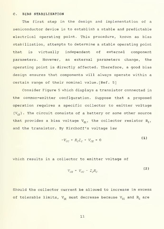
C. BIAS STABILIZATION
The first step in the design and implementation of a
semiconductor device is to establish a stable and predictable
electrical operating point. This procedure, known as bias
stabilization, attempts to determine a stable operating point
that is virtually independent of external component
parameters. However, as external parameters change, the
operating point is directly affected. Therefore, a good bias
design ensures that components will always operate within a
certain range of their nominal value. [Ref. 5]
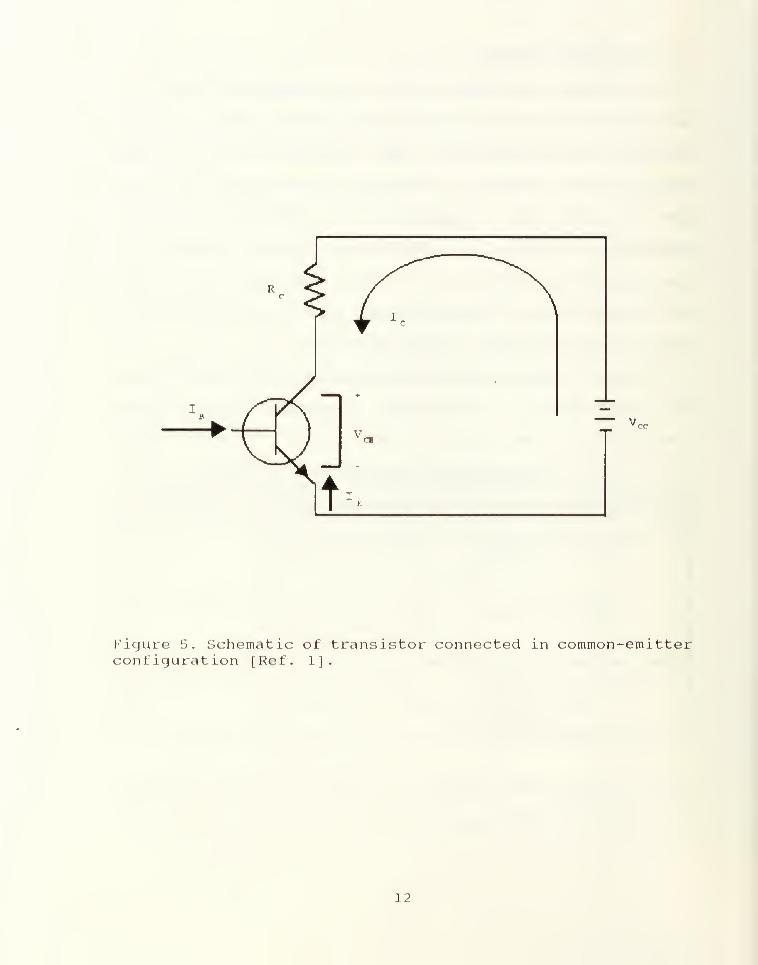
Consider Figure 5 which displays a transistor connected in
the common-emitter configuration. Suppose that a proposed
operation reguires a specific collector to emitter voltage
(VCE ) . The circuit consists of a battery or some other source
that provides a bias voltage Vcc , the collector resistor R
c ,
and the transistor. By Kirchoff's voltage law
-Vcc + RCIC + VCE =(1)
which results in a collector to emitter voltage of
VCE ~ VCC " ICRC(2)
Should the collector current be allowed to increase in excess
of tolerable limits, VCE
must decrease because Vcc
and Rcare
11
Page 25
Figure 5. Schematic of transistor connected in common-emitterconfiguration [Ref. 1).
12
Page 26
fixed values. Therefore, it should be noted that, if a high
junction temperature causes an increase in Ic
, VCE
can no
longer be maintained at the level desired to perform the
desired operation. [Ref . 1]
1. Operating in the Forward Bias Region
As an example of electronic component temperature
dependence, consider a diode operating in the forward bias
region. In the forward region the i-v relationship is closely
approximated by
i = Js (en^ - 1)
(3)
In this equation Isis a constant for a given diode at a given
temperature. The current Is
is usually called the saturation
current. However, another name for it is the scale current,
which arises from the fact that Isis directly proportional to
the cross-sectional area of the diode. Furthermore, it can be
seen in Table 2 that, Is
is a very strong function of
temperature. [Ref . 5]
The temperature relationship between Is
and the
forward current i is derived from the voltage VT
. This
constant, called the thermal voltage, is given by
VT = AT (4)Q
13
Page 27
where
k = Boltzman's constant, 1.38-10" 23 J/ K
T = the absolute temperature, K
q = the charge on the electron, 1.602 • 10" 19 C
Table 2 illustrates this relationship and emphasizes the need
to accurately analyze a proposed assembly prior to
fabrication.
TABLE 2. TEMPERATURE DEPENDENCY OF IsON i
FOR SELECTED MATERIALS
GERMANIUM SILICON
"C Is i I « i
25 3 . mA 18.01 mA 50.0 r?A 82.31 r?A
95 0.384 mA 1.47 3 mA 51.2 /xA 61.39 jLtA
165 4 9.2 mA 0. 136 A 52.4 mA 49.2 mA
D. CATASTROPHIC THERMAL FAILURE
Another of the primary goals of techniques in advanced
thermal control is to provide a thermal environment for a
diversity of components that are in increasingly close
proximity to each other. Figure 6 illustrates the increasing
level of packaging densities. With increasing complexity comes
an increased level of connections between dissimilar material
and a greater possibility for exceeding temperature
limitations. Therefore, it is necessary that designers have
14
Page 28
10
10
§ 10o5°- 3
2 10cAC
| 102
oO
10
65K CCD Memory
IkMOSRam
RTL Logic Gate
4 Bit , TTL Counter
Dual Transistor Logic
Flip-Ftop
SSI- MSI LSI VLSI
1950 1960 1970 1980 1990Year
Figure 6. State of the art in circuit complexity [Ref. 1]
15
Page 29
some knowledge of the possible range of component and
environmental variations in order to prevent catastrophic
thermal failure.[Ref . 1]
Catastrophic thermal failure is defined as an immediate,
thermally induced, total loss of electronic function in a
specified component. This type of failure is the result of a
component melting due to excessive temperature, a thermal
fracture of the substrate or carrier, or a separation of leads
and the external network. It is generally considered to be
dependent on the local temperature field, operating history,
and operating modes of the component. As previously stated, a
variety of problems arise when components are subjected to
temperatures in excess of their rated limits. Furthermore, it
is extremely difficult to determine the precise temperature at
which catastrophic failure may occur. The incorporation of an
accurate thermal analysis, in combination with test and
operating experience, may be used to generate a catastrophe
free upper operating limit. These maximum allowable operating
temperatures are used to generate the master thermal control
configuration for the system. [Ref . 1
]
16
Page 30
III. HEAT TRANSFER
Heat transfer is defined as all energy flows that arise as
a result of temperature differences [Ref. 6]. Because
electronic components are not one hundred percent efficient,
they produce heat as well as the desired output. In the case
of semiconductor devices, heat develops in parts having low
thermal efficiencies, such as the die. One of the major
objectives of packaging is to develop an effective system for
the removal of heat from these parts [Ref. 4]. It is
imperative that design engineers understand all modes of heat
transfer in order to incorporate an efficient method of heat
removal into component designs. The modes of heat transfer are
conduction, convection, and radiation.
A. CONDUCTION
Conduction is the transfer by molecular motion of heat
between one part of a body to another part of the same body or
between one body and another in physical contact [Ref. 1] .
Joseph Fourier, a French physicist, proposed that the rate of
heat flow through a material by conduction is proportional to
the area of the material normal to the heat flow path and to
the temperature gradient along the heat flow path.
17
Page 31
This proportionality is represented mathematically by
s dT(5 »
where the minus sign allows for a positive heat flow in the
presence of a negative temperature gradient. The introduction
of a proportionality constant, known as thermal conductivity,
results in the following rate eguation which describes this
mechanism [Ref. 1]
:
g = -tag <6)
dx
where
k = thermal conductivity of the material, W/m- °
C
A = area of the heat flow path, m2
dT/dx = change in temperature per unit length, C/m
g = rate of heat flow, W
1. General Equation of Heat Conduction
The first step in the analytical solution of a heat
conduction problem for a given structure is to choose an
orthogonal coordinate system such that the surfaces coincide
with the boundary surfaces of the structure [Ref. 7]. In the
case of the model builder developed in this thesis, the
18
Page 32
rectangular coordinate system will be employed. The general
equation of heat conduction is given as
dx\ dx) dy\ dyj dz\ dzf2 K
dt
(7)
a^
Then, assuming k, C, and p are independent of temperature,
direction, and time, the resulting equation is
d2 T+
cPT+
&T_+ _g .
1 dTdx2 dy 2 dz 2 k a dt
(8)
where
T = temperature, C
x, y, and z = cartesian coordinates, m
t = time, sec
k = thermal conductivity, W/m- C
q = internal heat generation, W/m3
a = thermal diffusivity, k/pC, m2/sec
There are several variations of the general equation
of conduction. The first, known as the Fourier equation,
provides a solution for a system that contains no heat
sources:
82 T +c?T + _&T JL dT
(9)dx 2 dy2 dz 2 cc dt
19
Page 33
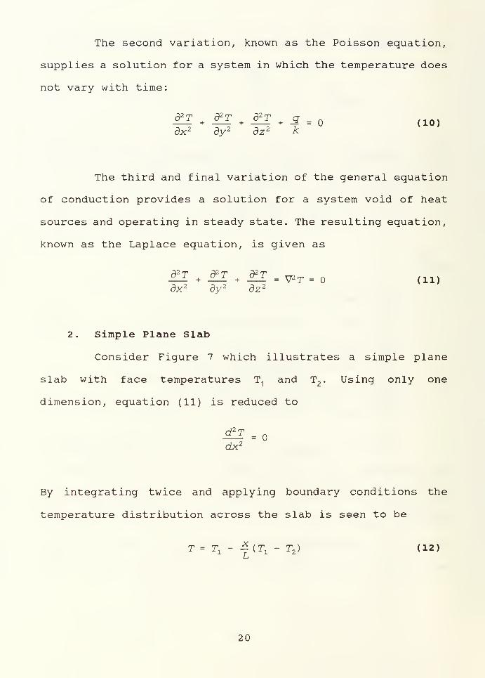
The second variation, known as the Poisson equation,
supplies a solution for a system in which the temperature does
not vary with time:
+ -2" = o (io)d2 T d2 T d2 Tdx2
+
dy 2+
dz 2 k
The third and final variation of the general equation
of conduction provides a solution for a system void of heat
sources and operating in steady state. The resulting equation,
known as the Laplace equation, is given as
dx 2 dy 2 dz :
2. Simple Plane Slab
Consider Figure 7 which illustrates a simple plane
slab with face temperatures T1
and T2
. Using only one
dimension, equation (11) is reduced to
d2 T=
dx'1
By integrating twice and applying boundary conditions the
temperature distribution across the slab is seen to be
T = Tx
- — {T1
- T2 ) (12)
J—
i
20
Page 34
Ti
X
k
^__X=0
Figure 7. Conduction heat transfer through a simpleplane slab.
21
Page 35
Insertion of equation (12) into equation (6) produces a
solution for the heat flow across the slab:
g = -kAL
= M( Tl - T2 )
d3)
Ohm's Law indicates a direct analoqy between heat
flow, equation (13), and the flow of electrical current
throuqh a resistor, V = RI . This electrothermal analoqy is
extremely useful in the solution of one dimensional, steady
state problems without enerqy qeneration and will be developed
further in the next section. [Ref. 8]
3. Electrothermal Analog
As previously stated, there is a direct analogy
between heat flow across a simple plane slab, equation (13),
and electrical current governed by Ohm's law:
In this case, the analogous quantities are
Current I ** Heat Flow q
Potential V +» Temperature Difference AT
Resistance R <- Thermal Resistance R
22
Page 36
It is easily seen that for the heat flow in a simple
plane slab described by, equation (13) , the thermal resistance
is
R-AI = J^ (15 )
q kA
The electrothermal analog for conduction across a simple plane
slab is shown in Figure 8.[Ref. 1]
B. CONVECTION
Convection is defined as the process by which thermal
energy is transferred to or from a solid by a fluid flowing
past it. Should the fluid flow be the result of a temperature
difference the phenomena is called natural or free convection.
On the other hand, when a pump or fan causes the mass movement
the process is called forced convection. [Ref. 1]
Recall that at the interface between a solid and a fluid
that heat is transferred by conduction and must obey Fourier's
law, equation (6) . Due to the difficulty encountered in
accurately measuring the temperature gradient, Newton
suggested that the surface heat transfer rate be related to
the product of surface area and the temperature difference
between the surface and the fluid. The results of this
proposition lead to Newton's law of cooling:
q = hA(T - Tf )
(16)
23
Page 37
Tx-T 2R= kA
Figure 8. Conduction Electrothermal Analog.
24
Page 38
where h is a proportionality factor that has become known as
the surface heat transfer coef f icient.[Ref . 1]
From a comparison of Newton's law of cooling, equation
(16), and Fourier's law, equation (6), one can derive that the
surface heat transfer coefficient can be related to the
thermal conductivity, the wall temperature gradient of the
fluid, and the surface fluid temperature difference:
h = dyj (17)
A-AT AT
Therefore, any correlation between heat transfer coefficients
must reflect the dependence of h on the thermal conductivity
of the fluid and on the ratio of the wall temperature gradient
to the temperature difference. [Ref . 1]
1. Electrothermal Analog
The addition of heat transfer by convection to both
surfaces of the simple plane slab of Figure 7 results in the
configuration shown in Figure 9. In the convective case
thermal resistance is represented by
R = _L (18)hA
25
Page 39
Figure 9. Convective heat transfer on a simple plane slab.
26
Page 40
Therefore, the total thermal resistance is
R =h
yA
LkA h
2A hi
L
k(19)
which is represented by the electrothermal analog shown in
Figure 10. A simple consideration of circuit theory then shows
that
:
Q = ATR
(Tx - T2 )
1
AA +
Ak +k
1
h2.
(20)
C. RADIATION
Heat transfer by radiation is the means by which thermal
energy can be transmitted through a space without an
intervening medium while obeying the laws of electromagnetics.
Thermal radiation, while traveling at the speed of light, may
be absorbed, reflected, or transmitted upon contact with a
surface. An ideal black body absorbs all incident radiation
and reflects and transmits none of it. The concept of the
black body is useful because laws governing its radiation are
simple and many real bodies may be treated approximately as
black bodies [Ref. 1].
Materials used in the fabrication of electronic components
are classified as gray. Gray bodies are diffusely reflecting
27
Page 41
T,
T -T11
1:
A/WVh
1A
h.A
A/WV
R=kA
Figure 10equivalent.
Conduction and convection electrothermal
28
Page 42
opaque surfaces [Ref. 4]. These surfaces reflect equal amounts
of energy over the thermal radiation spectrum (wavelengths of
about 0.1 fj.m to about 100 fim) in all directions. The heat
transfer efficiency of this mode depends on the configuration,
the orientation, and the temperatures of the surfaces in the
electronic assembly.
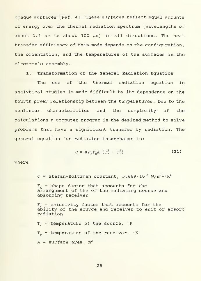
1. Transformation of the General Radiation Equation
The use of the thermal radiation equation in
analytical studies is made difficult by its dependence on the
fourth power relationship between the temperatures. Due to the
nonlinear characteristics and the complexity of the
calculations a computer program is the desired method to solve
problems that have a significant transfer by radiation. The
general equation for radiation interchange is:
q = oF^tA (Tt - rj) (21)
where
a = Stefan-Boltzman constant, 5.669- 10" 8 W/m2-'K4
FA= shape factor that accounts for the
arrangement of the of the radiating source andabsorbing receiver
F = emissivity factor that accounts for theability of the source and receiver to emit or absorbradiation
Ts= temperature of the source, °K
Tr= temperature of the receiver, K
A = surface area, m2
29
Page 43
It is important to note that the absolute temperature scale
must be used when considering radiation.
One way to handle computations involving heat transfer
by radiation is to transform the general radiation equation,
equation (21), into a configuration compatible with Fourier's
law. In this case, linearization of the general radiation
equation is the method used to produce the desired result.
This is achieved by factoring the difference in the fourth
power of the temperatures as follows:
CrJ - tJ) = ai + t2) (t; - t2
)
= (T2
S + T2,) (Ts + T
z ) (Ts- Tx )
(22)
Inserting this into equation (21) results in
q = oFAFeA (7i + ij) (Ts + Tz ) (Ts - Tr )
(23)
A radiative heat transfer coefficient may therefore be defined
as
or
h r= oFAFE (T
2
s * li) (Ts + TR )(24a)
^r " O^^s + T2
5 TR + TST2
R + 7^) (24b)
30
Page 44
Then, substituting hr
into equation (23), radiation heat
transfer may be treated exactly as convection at the boundary.
A thermal resistance for radiation heat transfer can
now be proposed:
R = 1
h^A(25)
Figure 11 provides an illustration of the electrothermal
equivalent with the addition of radiation resistance in
parallel with convective resistance.
R-h r A
1
R=kA
R=h, A
T,
Figure 11. Radiation, convection, and conductionelectrothermal equivalent.
31
Page 45
2. General Problems of Heat Transfer by Radiation
In the calculation of heat transfer by radiation, it
is usually necessary to approximate real-body behavior by the
gray-body idealization. The assumption that emissivity is
always equal to absorptivity is frequently required if the
problem is to be solved. Even a simple situation becomes quite
complex if real body behavior is considered and the resulting
convenience of replacing absorptivity with emissivity is lost.
A second difficulty in considering real-body behavior is the
lack of sufficient data. To properly account for real-body
behavior, extensive tabulations would be required. [Ref . 6]
The usual problem of heat transfer by radiation is
further complicated not only because the surfaces are nonblack
but also because the configuration of the areas involved is
not simple and reflecting surfaces may be present to augment
the direct exchange [Ref. 6]. There are a number of methods
available to assist in the solution of heat transfer by
radiation, however, their development is beyond the scope of
this thesis.
32
Page 46
IV. FINITE DIFFERENCES
The need to utilize a computer to determine the
temperature distribution within an electronic component or
system has made finite difference methods very desirable. This
numerical method is useful in problems involving
nonlinearities, complex geometries, complicated boundary
conditions, or a system of coupled partial differential
equations. The purpose of this section is to provide the
reader with some basic concepts involved in finite difference
methods for solving differential equations. Furthermore, it
demonstrates the methodology used to formulate «-node
equations in n-unknown temperatures and instills confidence
that this numerical method is capable of generating an
accurate thermal model
.
A. FUNDAMENTAL CONCEPTS
Consider equation (7) , the general equation for heat
transfer by conduction. In order to produce a numerical
solution to a conduction heat transfer problem it is necessary
to reconfigure the partial differential equation into a form
that allows differentiation to be performed by numerical
methods. Therefore, it is essential that accurate
approximations of the first and second derivatives be
obtained.
33
Page 47
1. First Derivative Approximation
The derivative of a function at any point can be
expressed by a finite difference approximation by
incorporating a Taylor series expansion about that point.
Consider Figure 12 where T(x) is a function that can be
expanded by a Taylor series. The Taylor series expansions of
the functions T(x+Ax) and T(x-Ax) about a point x are:
T(x+Ax) = T(x) + AxT'(x) *(A*)2
r"(x) + SA^1t'"{x) +... (26a)
T(x-Ax) = T(x) - AxT'(x) +(A*)2
r"(x) - (Ax)3 T1" (x) + . . . (26b)
In order to determine the first derivative, eguations (26a)
and (26b) are solved for T' (x)
.
T'(x) =T(x + Ax) " ™ - (Ax) T"(x) -
{Ax)2T'"(x) -... (27)
Ax 2 6
T'(x) =T{x) ' T(x ' Ax)
*(Ax)
T"(x) -(Ax) V"(x) +... (28)
Ax 2 6
Subtracting equation (26b) from (26a) and solving for T' (x)
produces
T'(x) =T(<X + Ax) ~ r(x
-Ax) - (Ax)2
T'"{x) - (29)2Ax 6
34
Page 48
T(x)
X
Figure 12. First and second derivative approximations
35
Page 49
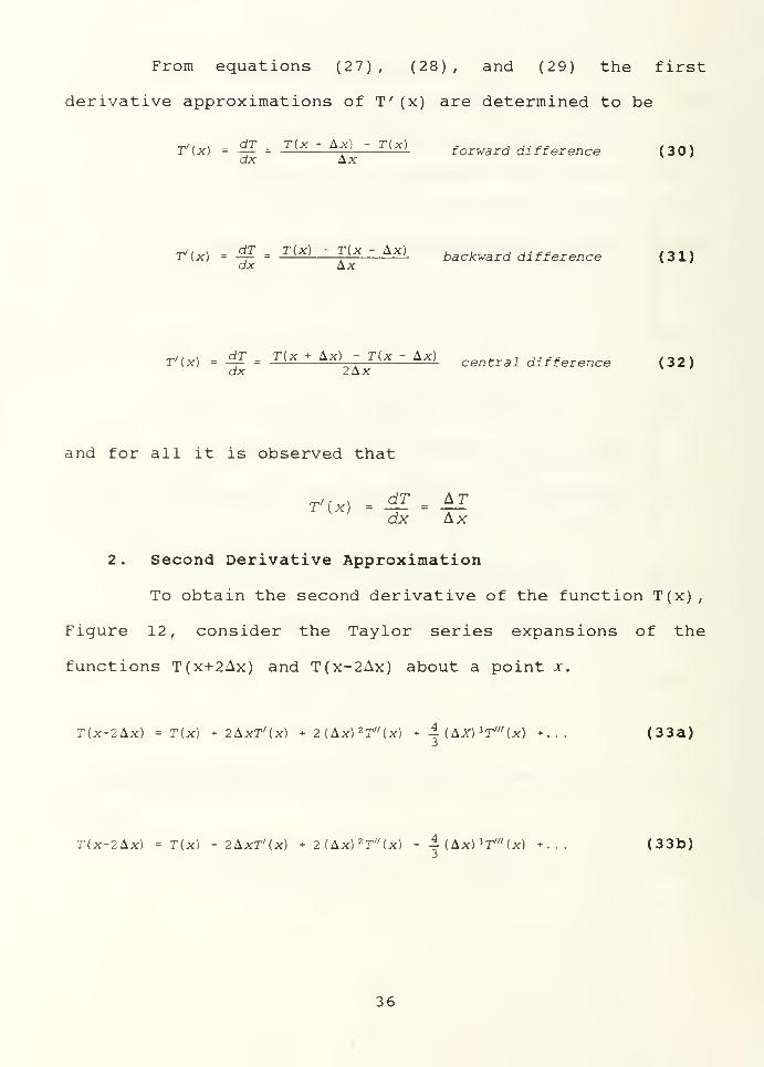
From equations (27) , (28) , and (29) the first
derivative approximations of T" (x) are determined to be
T'ix) = <£ = r <* + Af - r( *> forward difference (30)dx Ax
T'ix) = j? =T(x) ~ T
K
(X ~ Ax) backward difference (31)
r'(x) = i£ = T(x + Ax) - r(x - Ax) central different (32 )dx 2Ax
and for all it is observed that
r'ui - ^ -41dx Ax
2 . Second Derivative Approximation
To obtain the second derivative of the function T(x),
Figure 12, consider the Taylor series expansions of the
functions T(x+2Ax) and T(x-2Ax) about a point jc.
T(x+2Ax) = T(x) + 2Axr'(x) + 2(Ax) 2 T"(x) + -| ( AX) l T'"(x) + ... (33a)
T(x-2Ax) = T(x) -2AxT'U) + 2(Ax) 2 T//(x) - 4- ( Ax) l T'" (x) +... (33b)
36
Page 50
Inserting the corresponding first derivative approximation
into eguations (33a) and (33b) and solving for T" (x) results
in
T"{x) = ^ = T(x) + T(x + 2Ax) - 2T(x * Ax) foiward difference (34)dx 2 (Ax) 2
T»{x) = -^ =TU ~ 2AX) + T(X) ~ 2T{X ~ AX) backward difference (35)
dx2 (Ax) 2
The central difference is obtained by eliminating TV (x)
between equations (26a) and (26b)
.
r» (x) = *1 = r<x - Ax) ; T(x * Ax) - 2T(x)ce/]trai difference ( 36 )
dx2 (Ax) 2
and for all it is observed that
T"U) =d" T {AT)
dx 2 (Ax)
B. NODE ANALYSIS
The first step in the physical formulation of a solution
by node analysis is, as previously stated, to divide the
region into a finite number of subvolumes as shown in
Figure 13. The centroid of each subvolume is called a node and
is considered to be representative of the entire subvolume.
37
Page 51
/«
21 22 23 24
76
17 / 18 / 19 20
/44/
72
13 14 > 15 16
/40/
68
/ 9 X 10 y/ 11 12
/3 6/
64
/ 5 / 6 7 y 8
/32/
60
/ 1 / 2 3 / 4
56
25 26 27 28
/ / ~zL / /49 50 51 52
V8
Figure 13. Structure divided intosubvolumes
.
38
Page 52
At this point, continuity must be applied. In the steady
state, the algebraic sum of all the heat leaving any node must
equal zero. As an example, consider an interior node on the
upper layer; select node number 14. Figure 14 provides an
expanded picture around node-14. In order to maintain clarity
the external environment will be considered as a single node,
number 81. The resulting energy balance or node equation can
be written as
#14. 10+
<2i4 ,13+
<3i4.15+
^14,18+
^14, 38+
^14.31+
<?i = ° < 37 >
Here, each numerical subscript represents the heat flow from
node-14 to the indicated node. Furthermore, q. allows for
energy input by an external source such as a dissipating
component
.
The energy balance simply supplies the pertinent energy
terms. It is important to note that differences in thicknesses
and thermal conductivities must be taken into consideration.
The rate equations may be written in terms of thermal
resistances and temperature differences:
Jc.AxAz,, , ,__ .
n = — - (T - T ,) (38a)^14, 13 A „ V X 14 J 13' x '
Jc,AxAz, , /-,„»_»a = — - (T - T ) (38b)^14,15 K y
V 't 14 ^lS' x'
39
Page 53
AAAV
18
Ay
Figure 14
40
Page 54
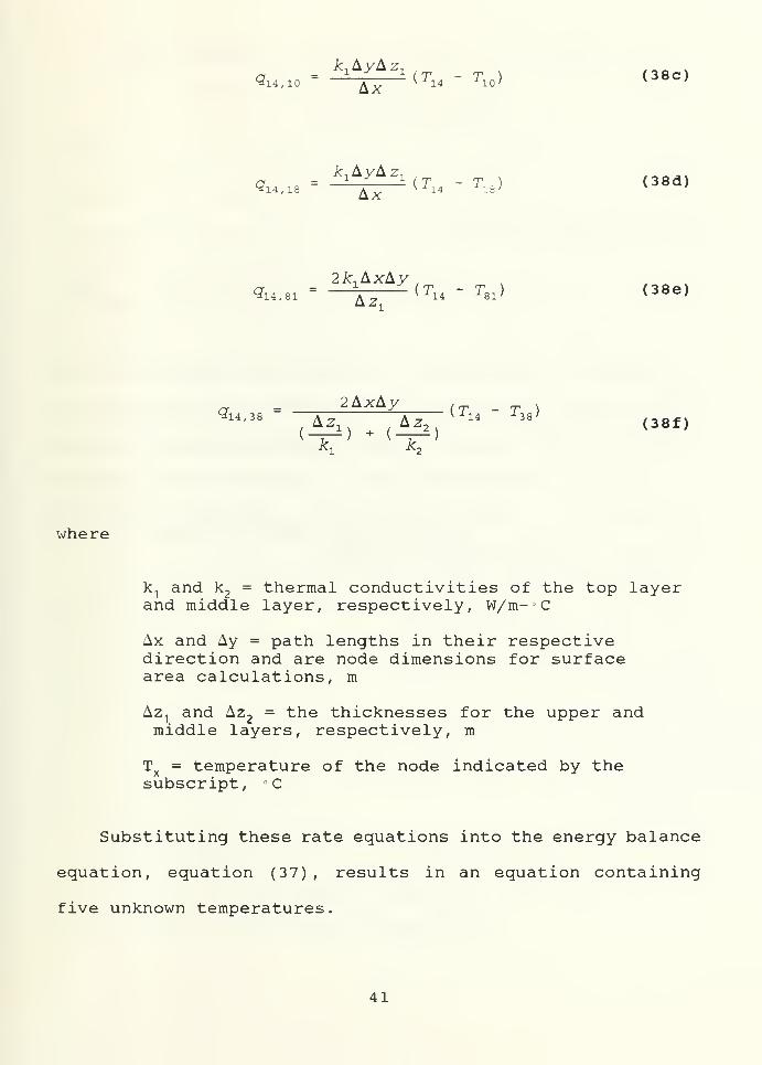
where
Sn.io £x
—
(Ti4 " Tio) (38c)
icAyAz, ,„„,,»a . = _J_ i(T - TJ (38d)^14, 18 A x
v x 14-118 ' x '
2ic,AxAy, ,
314 ,8i " ~\-z
(r14 " T81 ) (38e)
g14, 3(
2AxAy , - t \
Az Az 14 38 f3«f}
^1 ^2
k1and k
2= thermal conductivities of the top layer
and middle layer, respectively, W/m- C
Ax and Ay = path lengths in their respectivedirection and are node dimensions for surfacearea calculations, m
Az1and Az
2= the thicknesses for the upper and
middle layers, respectively, m
Tx= temperature of the node indicated by the
subscript, °C
Substituting these rate equations into the energy balance
equation, equation (37) , results in an equation containing
five unknown temperatures.
41
Page 55
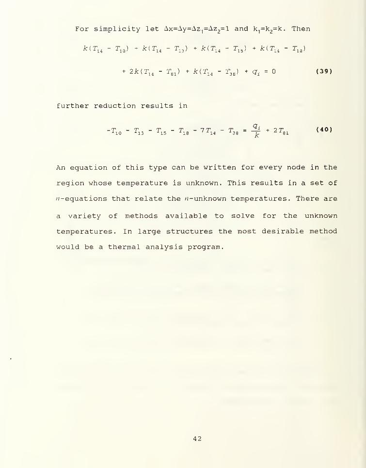
For simplicity let Ax=Ay=Az1
=Az2=l and k
1=k
2=k. Then
k(Tl4- r10 ) - k(T1A
- r13 ) - k(TlA- r15 ) + Jc<r14 - r18 )
+ 2k(Tl4
- T61 ) + /c(T14 - T38 ) + qd= (39)
further reduction results in
_7> _ T _ J- _ 7> _ 77 _ J- - _£i + tt (40)-'lO -^13 J 15 1 1S ' i i4 ^38 u.
AJ-B1 y'
An equation of this type can be written for every node in the
region whose temperature is unknown. This results in a set of
/^-equations that relate the /2-unknown temperatures. There are
a variety of methods available to solve for the unknown
temperatures. In large structures the most desirable method
would be a thermal analysis program.
42
Page 56
V. THE MODEL BUILDER
As previously stated, the model builder currently being
used by the thermal analysis software package requires an
inordinate amount of time for data entry. This thesis presents
a specific model builder, TMDL, that will become part of the
software package. TMDL provides a user friendly, rapid method
to assist in the development of a thermal model with a
specific geometry as in Figure 2. Specifically, it generates
a properly formatted output data file for use by the thermal
analyzer enroute to preparing an accurate listing of the
temperature distribution of the structure.
A. THE THERMAL ANALYZER INPUT DATA FILE
The model builder generates a data file from physical
characteristics of the structure provided by the user. This
data file, also called the thermal analyzer input data file,
must be in a format that is completely acceptable to the
thermal analyzer. Furthermore, it will consist of five lines
and up to seven data sets. This section describes each line
and data set and their relationship with TMDL. Figure 15
displays a partial data file.
Line one is the title line. It may be left blank or may
contain up to 79 alphanumeric characters. The user selected
title appears at the top of the data file.
43
Page 57
EXAMPLE OUTPUT DATA FILE740 6 2
750 50
.0500000 . <
6 2 4 6
5666700 12 .8000000 78 .0000076.500000000 76.900000000 75. 900000000 77.100000000 77.400000000 75.6000
7 7551 21 7521 111 7511 241173.700 36.850 87. 709 43.855 2.047 1. 4566 11 31 7521 121 7511 242136.850 36.850 87. 709 43.855 2.047 1. 4567 21 41 7521 131 7511 243136.850 36.850 87. 709 43.855 2.047 1. 4566 31 51 7521 141 7511 244136.850 36.850 87. 709 43.855 2.047 1. 4566 41 61 7521 151 7511 245136.850 36.850 87 709 43.855 2.047 1. 4566 51 71 7521 161 7511 246136.850 36.850 87 709 43.855 2.047 1. 4567 61 81 7521 171 7511 247136.850 36.850 87 709 43.855 2.047 1. 4566 71 91 7521 181 7511 248136.850 36.850 87 709 43.855 2.047 1. 4566 81 101 7521 191 7511 249136.850 36.850 87 709 43.855 2.047 1 4567 91 7541 7521 201 7511 250136.850 73.700 87 .709 43.855 2.047 1 4566 7551 121 11 211 7511 251173.700 36.850 43 .855 43.855 2.047 1 4566 111 131 21 221 7511 252136.850 36.850 43 .855 43.855 2.047 1 4567 121 141 31 231 7511 253136.850 36.850 43 .855 43.855 2.047 1 4566 131 151 41 241 7511 254136.850 36.850 43 .855 43.855 2.047 1 .4566 141 161 51 251 7511 255136.850 36.850 43 .855 43.855 2.047 1 .4566 151 171 61 261 7511 256136.850 36.850 43 .855 43.855 2.047 1 .4566 161 181 71 271 7511 257136.850 36.850 43 .855 43.855 2.047 1 .4566 171 191 81 281 7511 258136.850 36.850 43 .855 43.855 2.047 1 .4567 181 201 91 291 7511 259136.850 36.850 43 .855 43.855 2.047 1 .4566 191 7541 101 301 7511 260136.850 73.700 43 .855 43.855 2.047 1 .4566 7551 221 111 311 7511 261173.700 36.850 43 .855 43.855 2.047 1 .4566 211 231 121 321 7511 262136.850 36.850 43 .855 43.855 2.047 1 .456
Figure 15. Output data file.
44
Page 58
Line two is the problem data line. It has nine entries of
which two are under user control, number of nodes under
consideration and unit type. One entry, the number of constant
temperatures is preset at six for this specific model. The
remaining entries have applications to models associated with
heaters, unique exponents, secondary heat input, temperature
coefficients and curves, and nodes controlling fast heat.
These entries are not applicable to this model and are preset
to zero.
Line three places a zero at three points and is beyond the
user's control. Therefore, no further discussion is required.
Line four is the problem capability line. This line
defines the maximum values for the entries in line two. The
first entry is 750, the number of nodes for which the analysis
is dimensioned. This is significant because the first constant
temperature will be assigned the node number 751. The second
entry is 50 which is the maximum number of constant
temperatures in accordance with the analyzer dimension
statement. Therefore, it is possible to have 50 constant
temperatures allocated from node 751 to 800. The third entry
is preset to six for an application concerning heaters and is
not applicable to this model. The balance of the entries in
line four represent a listing of data sets that are required
for the particular analysis at hand. TMDL uses three data sets
that will be discussed in what follows.
45
Page 59
Line five contains five items that concern the level of
accuracy that the thermal analyzer will achieve. These entries
are preset. Item one provides the desired level of accuracy
between iterations. Because the thermal analyzer solves
iteratively, there must be an error criterion at which point
calculations cease. A number that is too small will cause the
computer to run excessively and a number that is too large
will not give the desired accuracy. Therefore, a trade off is
necessary and such a tradeoff has indicated that 0.05 is
satisfactory. Item two is a damping factor that is used
between iterations to prevent temperature oscillations between
iterations. The third entry is the maximum number of
iterations. This prevents excessive computer time in the event
of faulty input data. Item four is a convergence factor that
adjusts the damping to close to the critical value. This means
that once the computer determines convergence is occurring,
slow convergence is increased to reduce computer time. The
fifth and final entry in line five is the initial temperature
at which the iterative process begins. It is input by the
user.
Input data set one contains temperature dependent
coefficients and is not used in this model.
Input data set two contains up to 50 constant temperature
inputs. This model has six constant ambient temperatures input
by the user.
46
Page 60
Input data set three involves heaters for fast warm up and
is not used in this model.
Input data set four contains all pertinent information
concerning the n-node equations. Each node requires two lines
of data. The odd numbered lines are used for specifying the
nodes that interact with the node in question and the modes by
which this interaction takes place. Consider Figure 14, line
one of data set four is as follows;
6 7551 21 7521 111 7511 2411
This line of data is for node number one of aspect ratio
selection one. The first entry provides the number of
connections to that node. Entry two says node 755, an ambient
temperature, is connected to the node in question and the one
indicates that the connection is by conduction. The rest of
the entries are read similarly with numbers between 7511 and
7561 indicating a conductive connection with the external
environment. External heat input is defined by entry 9991.
The even lines are used for specifying the inter node
conductance values of the corresponding entry in the previous
line.
Input data set five is used only if there are unique
exponents. Therefore, no further discussion is required.
Input data set six contains the initial temperature
guesses corresponding to the number of nodes receiving
47
Page 61
secondary heat and is not used in this model because they have
been set by the last entry in line five.
Input data set seven indicates the number of temperature
dependent heat input curves and is not used in this model.
B. FEATURES
TMDL is presented to the user in discrete sections. Upon
entry into the first section, the user is offered an optional
overview. This option should be accepted on at least the first
run. At the completion of the overview the user is prompted
for a data file name and title. The data file name should be
changed for each successive run because TMDL does not over
write existing files.
The second section provides prompts for the physical
characteristics of the structure. Initially, the user is given
a list of four aspect ratios from which to choose;
1.) 10 by 24 nodes provides a 1:2.4 ratio with 720 nodes.
2.) 15 by 15 nodes provides a 1:1 ratio with 675 nodes.
3.) 12 by 20 nodes provides a 1:1.6 ratio with 720 nodes.
4.) 8 by 30 nodes provides a 1:3.75 ratio with 720 nodes.
It should be noted that up to 30 additional nodes may be added
depending on the existence of the mounting ear. Figure 16
displays the specific geometry with definitions.
After selecting the desired aspect ratio, the user must
specify the use of either SI or English units. The input of
48
Page 62
LEFT
EAR
RIGHT
THICKNESS
BOTTOM
Figure 16.
49
Page 63
data must remain consistent with this selection. At this point
the input of structure characteristics are requested. These
entries consist of the length, width, thickness, and thermal
conductivity of each layer. There is ample opportunity for
correction or alteration throughout TMDL.
Section three requests the input of initial and ambient
temperatures. TMDL has six ambient temperatures.
The final section allows for the input of external heat
sources. TMDL provides for heat input into the upper substrate
surface only. There are four methods of external heat input
from which to choose. The first alternative allows for a total
rate of heat applied to the upper surface. An entry for this
alternative would be divided by the nodes and distributed
appropriately. Option two provides for the entry of average
heat per unit area. The third alternative gives the user the
freedom to enter heat in specifically selected nodes.
Option four offers no heat input.
At the conclusion of these entries an output data file
will be created in the proper format and placed in a file
named by the user.
50
Page 64
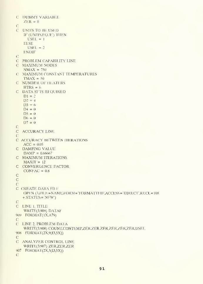
APPENDIX A
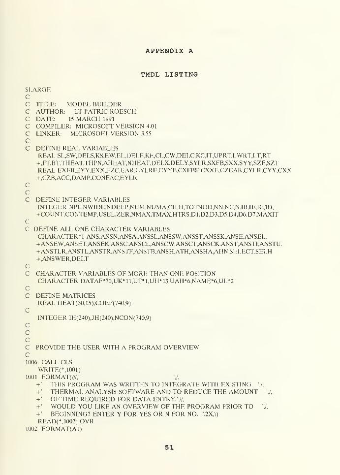
TMDL LISTING
SLAKGECC TITLE: MODEL BUILDERC AUTHOR: LT PATRIC ROESCHC DATE: 15 MARCH 1991
C COMPILER: MICROSOFT VERSION 4.01
C LINKER: MICROSOFT VERSION 3.55
CC DEFINE REAL VARIABLES
REALSL,SW,DELS,KS,EW,EL,DE1.E,KE,CL,CW,DELC,KC,IT,UPRT,LWRT,LT,RT+,FT,BT,THEAT,THPN,AHEAT,NHEAT,DELX,DELY,SYLR,SXFB,SXX,SYY,SZE,SZTREAL EXFB,EYY,EXX,EZC,EAR,CYLRE,CYYE.CXFBE,CXXE,CZEAR,CYLR,CYY,CXX+,CZB,ACC,DAMP,CONFAC,EYLR
CCC DEFINE INTEGER VARIABLES
INTEGER NPL,NWIDE,NDEEP,NUM,NUMA,CH,H,TOTNOD,NN,NC,N,IB,IE,IC,ID,+COUNT,CONTEMP,USEL,ZER,NMAX,TMAX,HTRS,Dl,D2,D3,D5,D4,D6,D7,MAXIT
CC DEFINE ALL ONE CHARACTER VARIABLES
CHARACTER* 1 ANS,ANSN,ANSA,ANSSL,ANSSW,ANSST,ANSSK,ANSE,ANSEL,+ANSEW,ANSET,ANSEK,ANSC,ANSCL,ANSCW,ANSCT,ANSCK,ANST,ANSTI,ANSTU,+ ANSTLR,ANSTL,ANSTR,ANSTF.ANSTB,ANSH,ATH,ANSHA,AHN,SLLECT,SELH+,ANSWER,DELT
CC CHARACTER VARIABLES OF MORE THAN ONE POSITION
CHARACTER DATAF*70,UK*11,UT*1,UH*13,UAH*6,NAME*6,UL*2CC DEFINE MATRICES
REAL HEAT(30,15),COEF(740,9)
CINTEGER IH(240),JH(240),NCON(740,9)
CCCC PROVIDE THE USER WITH A PROGRAM OVERVIEWC1006 CALL CLS
WRITE(UOOl)1001 FORMAT(///,' ',/,
+ ' THIS PROGRAM WAS WRITTEN TO INTEGRATE WITH EXISTING ',/,
+ • THERMAL ANALYSIS SOFrWARE AND TO REDUCE THE AMOUNT ',/,
+ ' OF TIME REQUIRED FOR DATA ENTRY.',//,
+ • WOULD YOU LIKE AN OVERVIEW OF THE PROGRAM PRIOR TO ',/,
+ ' BEGINNING? ENTER Y FOR YES OR N FOR NO. \2X,\)
READ(*,1002) OVR1002 FORMAT(Al)
51
Page 65
cIF (OVR.EQ.'Y'.OR.OVR.EQ.'y') THENCALL CLSWRITE(M003)
1003 FORMAT(///,' •»******* VERVIEW********* ',//,
+'
THIS PROGRAM PERFORMS A NODAL ANALYSIS OF A THREE ',/,
+ LAYERED CONDUCTIVE STRUCTURE (SUBSTRATE,EPOXY,AND ',/,
+ CARRIER). THE OUTPUT CONSISTS OF UP TO 740 COEFFI- 7,
+ ' CTENTS THAT CONTRIBUTE TO THE DETERMINATION OF ',/,
+' THE TEMPERATURE DISTRIBUTION OF A M1CROCIRCUIT ',/,
+ ' WHEN FED INTO THE THERMAL ANALYZER. ',//,
+• THE FOLLOWING IS AN ORDERED OUTLINE OF THE MAJOR ',/,
+ SECTIONS OF THIS PROGRAM AND WHAT ENTRIES ARE ',/,
+' REQUIRED OF THE USER. ',/,
+' NOTE THAT ALL ENTRIES WILL BE IN UPPER CASE LETTERS. ',/,
+'
A.) DATA FILE ',/,
+ 1.) ENTER THE TITLE OF THE OUTPUT DATA FILE. 'J,
+'
2.) ENTER THE DATA FILE NAME. THIS PROGRAM WILL NOT',/,
+' ERASE OR WRITE OVER EXISTING FILES. ',//,
+' PLEASE PRESS ENTER WHEN READY TO CONTINUE. \2X,\)
READ(*,1002)ANSWERC
CALL CLSWRITE(U004)
1004 FORMAT(///,' ',/,
+ ' B.) STRUCTURE PHYSICAL CHARACTERISTICS ',/,
+"
1.) SELECT UNIT TYPE (SI OR ENGLISH) ',/,
+ 2.) SELECT FROM FOUR ALTERNATIVES THE DESIRED NODAL',/,
+' ASPECT RATIO. ',/,
+'
3.) ENTER EACH LAYER CHARACTERISTICS. SUBSTRATE IS ',/,
+' THE TOP LAYER, FOLLOWED BY EPOXY AND THE CARRIER',/,
+ LAYERS, RESPECTIVELY. THE CARRIER LAYER MAY ',/,
+ CONTAIN AN EAR ON THE FRONT AND BACK SURFACES ',/,
+'
IF SPECIFICATIONS REQUIRE IT',//,
+ ' PLEASE PRESS ENTER WHEN READY TO CONTINUE. \2X,\)
READ(*,1002)ANSWERC
CALL CLSWRITE(*,1005)
1005 FORMAT(////,
+'
C.) INITIAL AND AMBIENT TEMPERATURES ',/,
+'
1.) ENTER INITIAL CHIP AND CHASIS TEMPERATURE. ',/,
+' ASSUME STEADY STATE FOR INITIAL TEMPERATURE.',/,
+'
2.) ENTER AMBIENT TEMPERATURES FROM ALL SIDES OF THE',/,
+' STRUCTURE.',//,+' D.) HEAT INPUT ',/,
+' HEAT INJECTION OCCURS ONLY ON THE UPPER SURFACE OF ',/,
+ ' THE SUBSTRATE LAYER. THIS PROGRAM SUPPLIES THE USER ',/,
+ ' FOR ALTERNATIVE METHODS FOR ENTERING HEAT; ',/,
+' 1.) TOTAL HEAT OVER SUFACE ',/,
+ '
2.) AVERAGE HEAT PER UNIT AREA ',/,
+•
3.) INPUT HEAT NODE BY NODE ',/,
+•
4.) NO HEAT INPUT ',//,
+'
THIS COMPLETES THE PROGRAM OVERVIEW. PLEASE PRESS ENTER ',/,
+ TO CONTINUE. \2X,\)
52
Page 66
READ( M002)ANSWERC
ELSEIF (OVR.EQ.'N'.OR.OVR.EQ.'n') THENGOTO 1007
ELSEGOTO 1006
1007 ENDIFCCCC INITIALIZE MATRICESC
DATA HEAT /450*0.0/
DATA IH /240*0/
DATA JH /240*0/
CC VARIABLE, CONSTANT AND SIRING DEFINITIONC PHYSICAL CHARACTERISTICSC SL,EL,CL - SUBSTRATE,EPOXY, AND CARRIER LENGTHSC SW,EW,CW - SUBSTRATE,EPOXY. AND CARRIER WIDTHSC KS,KE,KC - SUBSRATE.EPOXY.AND CARRIER THERMAL CONDUCTIVITIESC DELS,DELE,DELC - SUBSTRATE,EPOXY AND CARRIER THICKNESSC DELX - SL/NDEEPC DELY - SW/NWIDEC NPL - NUMBER OF NODES PER A LAYERC NWIDE - NUMBER OF NODES WIDEC NDEEP - NUMBER OF NODES DEEPC UL - UNITS OF LENGTH (SI OR ENGLISH)C UK - UNITS OF THERMAL CONDUCTIVITY (SI OR ENGLISH)C EAR - DEPTH OF THE EAR (SL-CL)/2
CC INITIAL AND AMBIENT TEMPERATURESC IT - INITIAL CHASIS AND CHIP TEMPERATUREC LT - LEFT SIDE AMBIENT TEMPERATUREC RT - RIGHT SIDE AMBIENT TEMPERATUREC FT - FRONT AMBIENT TEMPERATUREC BT - BACK AMBIENT TEMPERATUREC UPRT - UPPER AMBIENT TEMPERATUREC LWRT - LOWER AMBIENT TEMPERATUREC UT - UNITS OF TEMPERATURE (CENTIGRADE OR FARENHIET)CC HEAT INPUTC THEAT - TOTAL INJECTED HEATC THPN - TOTAL HEAT PER NODEC AHEAT - AVERAGE HEAT OVER A GIVEN SURFACEC NHEAT - HEAT PER NODE INJECTED NODE BY NODEC UH AND UAH - UNITS OF HEAT (SI OR ENGLISH)C NUM,NUMA,CH,H - DUMMY VARIABLES USED TO CREATE THE VECTORSC IH, & JH WHICH ARE USED TO RELATE NODEC NUMBER TO MATRIX POSITIONC TOTNOD,NN,NC,N - VARIABLES USED TO ALLOW HEAT INPUT NODALLYC IH,JH - VECTORS USED TO CORRELATE NODE NUMBER WITHC MATRIX POSITIONC HEAT - MATRIX USED TO CONTAIN HEAT INPUTSC
53
Page 67
C COEFFICIENT DEFINITIONS Y IMPLIES WIDTH & X IMPLIES DEPTHC Z IMPLIES HIEGHTC S IMPLIES SUBSTRATE, E IMPLIES EPOXYC C IMPLIES CARRIERCC SYLR - PROVIDES COEFFICIENT FOR LEFT OR RIGHT EDGE NODESC TO THE EXTERNAL NODE. SYLR IMPLIES SUBSTRATE,C EYLR - EPOXYC CYLR - CARRIER/ NO EARC CYLRE - CARRIER W/ EARCC SXFB - PROVIDES COEFFICIENT FOR FRONT AND BACK EDGE NODESC TO THE EXTERNAL NODE.C EXFB - EPOXYC CXFB - CARRIER/ NO EARC CXFBE - CARRIER W/ EARCC SYY - PROVIDES INTERNAL COEFFICIENT IN THE 'Y
1 DIRECTIONC EYY - EPOXYC CYY - CARRIER W/NO EARC CYYE - CARRIER W/ EARCC SXX - PROVIDE INTERNAL COEFFICIENT IN THE W DIRECTIONC EXX - EPOXYC CXX - CARRIER W/NO EARC CXXE - CARRIER W/ EARCC SZT - COEFFICIENT FOR SUBSTRATE TO UPPER EXTERNAL NODEC SZE - COEFFICIENT FOR SUBSTRATE TO EPOXYC EZC - COEFFICIENT FOR EPOXY TO CARRIERC CZEAR - COEFFICIENT FOR EAR TO LOWER EXTERNAL NODEC CZB - COEFFICIENT FOR CARRIER TO LOWER EXTERNAL NODECC CHARACTERC ALL ONE CHARACTER STRINGS EXCEPT 'UT' ARE SIMPLEC YES, NO, OR SELECTION ANSWERS AND DO NOT REQUIREC EXPLANATION.CC DATA FILEC DATAF - TITLE FOR DATA FILE, LINE ONEC NAME - DATA FILE NAMEC IB,IE,ID,IC - COUNTERS FOR FILLING DATA FILE
C COUNT - TOTAL NUMBER OF NODESC ACC - MINIMUM ERROR CRITERIA AT WHICH CALCULATIONS CEASEC DAMP - DAMPING FACTOR FOR PREVENTION OF TEMPERATUREC OSCILLATIONSC CONFAC - CONVERGENCE FACTOR USED TO INCREASE DAMPINGC CONTEMP - TMDL HAS 6 CONSTANT AMBIENT TEMPERATURESC USEL - TELLS ANALYZER WHAT TYPE OF UNITS ARF IN USEC ZER - DUMMY VARIABLEC NMAX - MAXIMUM NODES PROGRAM IS CAPABLE OF EVALUATINGC TMAX - MAXIMUM NUMBER OF CONSTANT TEMPERATURES PROGRAMC CAN ACCEPTC HTRS - NOT APPLICABLE TO THIS PROGRAM - NO EXPLANATIONC NECCESSARY
54
Page 68
C Dl-7 - DATA SETS IN USEC MAXIT - MAXIMUM ITERATIONS COMPUTER WILL PERFORM TOC ACHIEVE SOLUTIONCC BEGIN PROGRAMC
CALL CLSWRITE(*,406)
M )(> FO RM ATT ///' ******************#**#***#*#*#*****#*****#***
,*****' /
,• ******************************* * * ****************** /
i ** * +' /
+ ' ** PLEASE SELECT UPPER CASE LETTERS **',/,
+' ** PRIOR TO BEGINNING. **',/,
i' * * * * '
J
i i **************************************************' /
i i ****** ********************************************'\
CWRITE(*,201)
201 format(//,' ',/,
+ ' PRIOR TO ENTERING DATA INTO THIS PROGRAM ENSURE THAT',/,
+ ' YOU HAVE A DRAWING OF YOUR DESIGN AND ALL PERTINENT ',/,
+ ' DATA. ',//,
+ ' PRESS ENTER WHEN READY TO CONTINUE.',2X,\)
READ(*,304)ANSWERCC ALLOW USER TO NAME THE DATA FILE
CALL CLSC
WRITE(*,701)
701 FORMAT(///,' THIS PROGRAM CREATES AN OUTPUT DATA FILE FOR ENTRY+ INTO THE',/,
+ ' EXISTING THERMAL ANALYZER. FURTHERMORE. THIS PROGRAM DOES',/,
+ ' NOT ERASE OR WRITE OVER THE EXISTING DATA FILE. THEREFORE',/,+ ' THE USER WILL NAME THE DATA FILE FOR EACH RUN OF THIS ',/,
+ ' PROGRAM. THE FILE NAME IS LIMITED TO SIX CHARACTERS. ",//,
+ PLEASE ENTER THE DESIRED DATA FII.F NAME. ',2X,\j
READ 702, NAME702 FORMAT(A6)CCcC ALLOW USER TO PROVIDE TITLE LINE FOR DATA FILE
CALL CLSWRITE(*,202)
202 FORMAT(////,' ENTER THE DESIRED TITLE TO BE PLACED ON LINE+ ',/,' NUMBER ONE OF THE OUTPUT DATA FILE.',/,
+ '
\2X,\)
READ LDATAF1 FORMAT(A70)C7 CALL CLSCCC SUPPLY A LISTING OF ACCEPTABLE ASPECT RATIOS
55
Page 69
cWRITE (*,203)
203 FORMAT(/////,' THE FOLLOWING ASPECT RATIOS ARE AVAILABLE.')WRITE(*,204)
204 FORMAT(/,' 1.) 10 BY 24 PROVIDES A 1:2.4 RATIO WITH 740 NODES.4-',/,' 2.) 15 BY 15 PROVIDES A 1:1 RATIO WITH 675 NODES.',/,
+ • 3.) 12 BY 20 PROVIDES A 1:1.6 RATIO WITH 720 NODES.',/+,' 4.) 8 BY 30 PROVIDES A 1:3.75 RATIO WITH 720 NODES.',//
+ ,' PLEASE SELECT A NUMBER ONE THROUGH FOUR. ,2X,\)
READ(*,3020)SELECT3020 FORMAT(Al)CC USER CAN CONTINUE OR MAKE ANOTHER SELECTION
CALL CLSIF (SELECT.NE.T.AND.SELECT.NE.T.AND.SELECT.NE/3AND.SELECT.+NE.'4') THENGOTO 7
ELSE10 WRITE(*,3) SELECT3 FORMAT(//////,' YOU SELECTED NUMBER \A1,' OF THE FOLLO
+ WING 4 ALTERNATIVES.',//,+
'
1.) 10 BY 24 FOR A 1:2.4 RATIO',/,
+'
2.) 15 BY 15 FOR A 1:1 RATIO',/,
+'
3.) 12 BY 20 FOR A 1:1.6 RATIO',/,
+'
4.) 8 BY 30 FOR A 1:3.75 RATIO",//)
CENDIF
C5 WRITE(*,205)
205 FORMAT(' IS THIS THE DESIRED SELECTION. ENTER Y FOR YES AN+D N FOR NO. \2X,\)
READ(*, 8)ANSFORMAT(Al)
CC
IF (ANS.EQ.'N') THENGOTO 7
ELSEIF (ANS.EQ.Y') THENGOTO 9
ELSECALL CLSGOTO 10
9 ENDIFCC
CALL CLSCCC AFTER CONFIRMATION OF SELECTION FILL CONSTANTS WITH APPROPRIATEC VALUES
IF (SELECT.EQ.T) THENNWIDE = 10
NDEEP = 24
NPL = 240
56
Page 70
c
c
ELSEIF (SELECT.EQ.'2') THENNWIDE = 15
NDEEP = 15
NPL = 225
ELSEIF (SELECT.EQ.T) THENNWIDE = 12
NDEEP = 20
NPL = 240
ELSEIF (SELECT.EQ.'4') THENNWIDE = 8
NDEEP = 30
NPL = 240
ENDIFCC MAKE DESIRED UNIT SELECTIONC2 WRITE(*,206)
206 FORMAT(///////,' THIS PROGRAM IS CAPABLE OF OPERATIONS IN EI
+THER SI OR ',/,
+ ' ENGLISH UNITS. AFTER THE SELECTION OF THE UNITS, ALL ',/,
+•
ENTRIES MUST BE COMPATIBLE. PLEASE MAKE YOUR SELECTION.,/+// S FOR SI NOTATION,/,+ ' E FOR ENGLISH NOTATION \2X,\)
READ(*,302)ANSN302 FORMAT(Al)CC CHECK FOR CORRECT UNIT SELECTION4 IF (ANSN.EO.'S') THEN
WRITE(*,207)
207 FORMAT(////,' YOU SELECTED SI NOTATION.')ELSEIF (ANSN.EQ.'E) THENWRITE(*,208)
208 FORMAT(////.' YOU HAVE SELECTED ENGLISH NOTATION.')ELSECALL CLSGOTO 2
ENDIFC
WRITE(*,209)
209 FORMAT(' IS THIS THE DESIRED SELECTION? ENTER Y FOR YES AND+ N FOR NO. \2X,\)
READ(*,303)ANSA303 FORMAT(Al)CCC SHOULD I CONTINUE OR RESEI.ECT UNITS
IF (ANSAEQ.'Y') THENGOTO 6
ELSEIF (ANSAEQ.N ) THENCALL CLSGOTO 2
ELSECALL CLS
57
Page 71
WRITE(*,210)
210 FORMAT(///////,' THIS PROGRAM IS CAPABLE OF OPERATIONS IN
+ EITHER SI OR',/,
+' ENGLISH UNITS. AFTER THE SELECTION OF UNITS. ALL',/,
+'
ENTRIES MUSI" BE COMPATIBLE. PLEASE MAKE YOUR SELECTION.',/+/,' S FOR SI NOTATION.'./.
+'
E FOR ENGLISH NOTATION.')C
GOTO 4
6 ENDIFC
CALL CLSCp* ********************************* * * * V * * ********************* *********
c***************** ENTER CHIP CHARACTERISTICS FOR EACH LAYER***********p* ************************************** * ****************:**************
ccP*************************** * *stjBSTRATE LAYER * **************************
CWRITE(*,211)
2 1
1
FOR MATf in >****#***##$**#**#****#*###*#* + #** + * + #*######*####*## + *
.*#*#***#**** ********i
• '***************###*#****#cTjRSTRATE (CHARACTERISTICS**************** ******** * /
I******************************************************************
,********' f\
CC PROVIDE CORRECT UNIT ABBREVIATIONS
IP(ANSN.EO.S') THENWRITE(*,212)
212 FORMAT(' AI.L ENTRIES ARE IN SI NOTATION.',/)
UL = 'cm'
UK = 'Watis/cm/C'
UT = 'C
ELSEIF (ANSN.EQ.E') THENWRITE(*,213)
213 FORMATC AI.L ENTRIES ARE IN ENGLISH NOTATION.',/)
UL = 'in'
UK = 'Btu/hr/in/F
UT = 'F
ENDIFCCC
WRITE(*,220)UL220 FORMAT(' ENTER SUBSTRATE LENGTH (',A2,'): \2X,\)
READ *,SL
CWRITE(*,216)UL
216 FORMAT(/,' ENTER SUBSTRATE WIDTH (\A2,'): ,2X,\)
READ *,SW
CWRITE(*,217)UL
217 FORMAT(// ENTER SUBSTRATE THICKNESS (',A2,'): ',2X,\)
58
Page 72
READ *,DELSC
WRITE(*,218)UK218 FORMAT(/,' ENTER SUBSTRATE THERMAE CONDUCTIVITY (',A12,'): ',2X,\)
READ *,KS
C31 CALL CLSCC MAKE ANY CHANGES OR CORRECTIONS TO SUBSRATE ENTRIESC
WRITE(*,214)
214 FORMAT(///,- YOU HAVE MADE THE FOLLOWING ENTRIES FOR THE SUB
+STRATE.',/,)
20 PRINT *,' 1.) LENGTH \SL
PRINT *,' 2.) WIDTH \SWPRINT V 3.) THICKNESS \DELSPRINT *,' 4.) k \KS
CWRITE(*,215)
215 FORMAT(/,- DO YOU WISH TO MAKE ANY CHANGES? SELECT Y FOR YES
+ AND N FOR NO. \2X,\)
READ(*,304)ANSS304 FORMAT(Al)C
IF (ANSS.EQ.Y-
) THEN12 CALL CLS
WRITE(*,219)
219 FORMAT(////)
PRINT *,' THE CURRENT ENTRY FOR LENGTH IS \SL,' ',UL
WRITE(*,2190)
2190 FORMATf/,' WOULD YOU LIKE TO CHANGE THE LENGTH? (Y OR N)
+ \2X,\)
READ(*,304)ANSSLPRINT *
IF (ANSSL.EQ.'Y) THENWRITE(*,221)UL
221 FORMAT(// ENTER SUBSTRATE LENGTH (',A2,'): \2X,\)
READ *,SL
ELSEIF (ANSSL.EQ.'N) THENGOTO 14
ELSEGOTO 12
ENDIFC14 CALL CLS
WRITE(*,2191)
2191 FORMAT(////)
PRINT V THE CURRENT ENTRY FOR WIDTH IS \SW,' \ULWRITE(*,222)
222 FORMAT(/,' WOULD YOU LIKE TO CHANGE THE WIDTH? (Y OR N) ',
+2X,\)
READ(*,2192) ANSSW2192 FORMAT(Al)
IF (ANSSW.EQ.Y') THENWRITE(*,223)UL
59
Page 73
223 FORMAT(/,' ENTER SUBSTRATE WIDTH (',A2,'): ',2X,\)
READ *,SW
ELSEIF (ANSSW.EQ.'N') THENGOTO 13
ELSEGOTO 14
ENDIFCC13 CALL CLS
WRITE(*,2193)
2193 FORMAT(////)
PRINT *,' THE CURRENT ENTRY FOR THICKNESS IS '.DELS,' \ULWRITE(*,224)
224 FORMAT(/,' WOULD YOU LIKE TO CHANGE THE THICKNESS? (Y OR N)
+ \2X,\)
READ(*,2194) ANSST2194 FORMAT(Al)
IF (ANSST.EQ.'Y') THENWRITE(*,225)UL
225 PORMAT(/,' ENTER SUBSTRATE THICKNESS (\A2/): \2X,
+\)
READ *,DELSELSEIF (ANSST.EO.'N) THENGOTO 15
ELSEGOTO 13
ENDIFCC15 CALL CLS
WRITE(*,2195)
2195 FORMAT(////)
PRINT *,' THE CURRENT ENTRY FOR THERMAL CONDUCTIVITY IS \KS+,' \UK
WRITE(*,226)
226 FORMAT(/,' WOULD YOU LIKE TO CHANGE THE THERMAL CONDUCTIVIT+ Y? (YOR N) \2X,\)
READ(*,2196) ANSSK2196 FORMAT(Al)
IP" (ANSSK.EQ.'Y') THENWRITE(*,227)UK
227 FORMAT(/,- ENTER SUBSPRATE THERMAL. CONDUCTIVITY (\A1
+ 2,'): \2X,\)
READ *,KS
ELSEIF (ANSSKEO. N) THENGOTO 16
ELSEGOTO 15
ENDIFCC ALLOW ANOTHER REVIEW OF SUBSTRATE DATA ENTRIESC16 CALL CLS
WRITE(*,228)
60
Page 74
228 FORMAT(///,' YOU HAVE MADE THE FOLLOWING CORRECTIONS TO T+ HE SUBSTRATE ENTRIES.'//)
GOTO 20
CC
ELSEIF (ANSS.EO.N) THENGOTO 17
ELSEGOTO 31
ENDIFCC^*******************************ppQvy ( j 1 ARACTK' RIS I IC S* ******************
cc17 CALL CLS
WRITE(*,229)^29 FORMAT( ///
'******************************************************
I******************'
/
,'**************»************ppf-\vY Pi-fARAC IP p m'i*i f"1
^ **************** *
+ ' NOTE THAT SUBSTRATE AND EPOXY LENGTH AND WIDTH ARE EQUAL. ',/
+ )
CWRITE(*,230)UL
230 FORMAT(/,' ENTER EPOXY THICKNESS (',A2,'): \2X,\)
READ *,DELEWRITE(*,231)UK
231 FORMAT(/," ENTER EPOXY I'HERMAL CONDUCTIVITY (',A12,'): ',2X,\)
READ *,KE
CEL = SLEW = SW
CC REVIEW EPOXY ENTRIESC30 CALL CLS
WRITE(*,232)
232 FORMAT(///; YOU HAVE MADE THE FOLLOWING ENTRIES FOR THE EPOXY+ LAYER.',/)
32 PRINT V 1.) LENGTH \ELPRINT •,* 2.) WIDTH \EWPRINT •,' 3.) THICKNESS \DELEPRINT •,' 4.) k \KE
CWRITE(*,233)
233 FORMAT(/,' NOTE THAT CHANGING EPOXY LENGTH OR WIDTH ALSO CHANG+ES',/,' SUBSTRATE LENGTH OR WIDTH.',//,
+ ' DO YOU WISH TO MAKE ANY CHANGES TO THE EPOXY ENTRIES? (Y OR+ N) \2X,\)
READ(*.2197) ANSE2197 FORMAT(Al)C
61
Page 75
C MAKE ANY CHANGES OR CORRECTIONS TO EPOXY ENTRIESC
IF (ANSE.EQ.'Y') THEN22 CALL CLS
WRITE(*,2198)
2198 FORMAT(////)
PRINT *,' THE CURRENT ENTRY FOR LENGTH IS 'EL,' \ULWRITE(*,234)
234 FORMAT(/,' WOULD YOU LIKE TO CHANGE THE LENGTH? (Y OR N)
+\2X,\)
READ(*,2199) ANSEL2199 FORMAT(Al)C
IF (ANSELEQ.'Y) THENWRITE(*,235)UL
235 FORMAT(/,' ENTER EPOXY LENGTH (\A2,'): ',2X,\)
READ *,EL
SL = ELELSEIF (ANSLL.LQ.'N) THENGOTO 21
ELSEGOTO 22
21 ENDIFC24 CALL CLS
WRITE(*,601)
601 FORMAT(////)
PRINT •,* THE CURRENT ENTRY FOR WIDTH IS ',EW,' ',UL
WRITE(*,236)
236 FORMAT(/,' WOULD YOU LIKE TO CHANGE THE WIDTH? (Y OR N)
+ \2X,\)
READ(*,602)ANSEW602 FORMAT(Al)C
IF (ANSEWEO.'Y) THENWRITE(*,237)UL
237 FORMAT(// ENTER EPOXY WIDTH (\A2,): \2X,\)
READ *,EWSW = EW
ELSEIF (ANSEWEO.N) THENGOTO 23
ELSEGOTO 24
23 ENDIFC26 CALL CLS
WRITE(*,603)
603 FORMAT(////)
PRINT •,' THE CURRENT ENTRY FOR THICKNESS IS \DELE,' ',UL
WRITE(*,238)
238 FORMAT(/,' WOULD YOU LIKE TO CHANGE THE THICKNESS? (Y OR N)
+ \2X,\)
READ(*,604)ANSET604 FORMAT(Al)C
62
Page 76
IF (ANSET.HO.'V) THENWRITE(*,239)UL
239 FORMAT(/,' ENTER EPOXY THICKNESS (\A2,'): \2X,\)
READ *,DELEELSEIF (ANSET.EQ.'N) THENGOTO 25
ELSEGOTO 26
25 ENDIFC28 CALL CLS
WRITE(*,605)
605 FORMAT(////)
print v the current entry for thermal conductivity is \ke+: \uk
WRITE(*,240)
240 FORMAT(/,' WOULD YOU LIKE TO CHANGE THE THERMAL CONDUCTIVIT+ Y? (Y OR N) \2X,\)
READ(*.606)ANSEK606 FORMAT(Al)C
IF (ANSEK.EO.'Y) THENWRITE(\241)UK
241 FORMAT(/,' ENTER EPOXY THERMAL CONDUCTIVITY (\A12,*)
+: ',2X,\)
READ *,KE
ELSEIF (ANSEK.EQ.'N) THENGOTO 27
ELSEGOTO 28
ENDIFCC PROVIDE ANOTHER REVIEW OF EPOXY ENTRIESC27 CALL CLS
WRITE(*,242)
242 FORMAT(///,' YOU HAVE MADE THE FOLLOWING CORRECTIONS TO THE EP+OXY ENTRIES.'//)
GOTO 32
CELSEIF (ANSE.EQ.'N') THENGOTO 29
ELSEGOTO 30
ENDIFCCp***************** + ************r, Ajjnipo ('waRAC IFR I STICS *****************
Cc29 CALL CLS
WRITE(*,243)""43 FORMATS ////
'********** + ******************************************
I * * * * * * * * * * * * * * * * * « * * * * * * * * v * * i - \i
) 1 11
1 .
]
> PHAR ArTpRTSTIPS*************
63
Page 77
I-*****************************************************************
I********' IIS
c944 WRITE(*,244)UL244 FORMAT(' ENTER CARRIER LENGTH C,A2,'): ',2X,\)
READ *,CL
CC CARRIER LENGTH MUST BE GREATER THAN OR EQUAL TO SUBSTRATE LENGTHC
IF (CL.LT.SL) THENCALL CLSWRITE(*,243)
PRINT *,' CARRIER LENGTH MUST BE GREATER THAN OR EQUAL TO SUBS+TRATE LENGTH. '
GOTO 944
ENDIFCC
WRITE(*,246)UL246 FORMAT(/,' ENTER CARRIER THICKNESS (\A2/): \2X,\)
READ *,DELCC
WRITE(*,247)UK247 FORMAT(// ENTER CARRIER THERMAL CONDUCTIVITY (\A12/): \2X,\)
READ *,KC
C38 CALL CLS
CW = SWCC REVIEW CARRIER ENTRIESC
WRITE(*,248)
248 FORMAT(///,' YOU HAVE MADE THE FOLLOWING ENTRIES FOR THE CARRI+ER.V)
36 PRINT *,' L.) LENGTH XLPRINT *,' 2.) WIDTH \CWPRINT •,' 3.) THICKNESS \DELCPRINT V 4.) k \KCPRINT *
PRINT V CHANGING WIDTH WILL ALSO CHANGE SUBSTRATE AND EPOXY W+ IDTHS.
-
CWRITE(*,249)
249 FORMAT(/,' DO YOU WISH TO MAKE ANY CHANGES? (Y OR N) \2X,\)
READ(*,607)ANSC607 FORMAT(Al)CC MAKE CORRECTIONS OR CHANGES TO CARRIER ENTRIESC
IF (ANSCEQ.'V) THEN33 CALL CLS
WRITE(*,608)
608 FORMAT(////)
933 PRINT*/ THE CURRENT ENTRY FOR LENGTH IS \CL/ \UL
64
Page 78
WRITE(*,250)250 FORMAT(/,' WOULD YOU LIKE TO CHANGE LENGTH? (Y OR N) \2X,
+\)
READ(*,609)ANSCL609 FORMAT(Al)C
IF (ANSCL.EQ.'Y') THENWRITE(*,251)UL
251 FORMA'['(/; ENTER CARRIER LENGTH (',A2,'): \2X,\)
READ *,CL
IF (CL.LT.SL) THINCALL CLSWRITE(*,610)
010 FORMAT(////)
PRINT *,' CARRIER LENGTH MUST BE GREATER THAN OR EQ+ UAL TO SUBSTRATE LENGTH.'
PRINT V Till PRESENT INTRY FOR SUBSTRATE LENGTH IS
+ \SL/ \ULPRINT *
GOTO 933
ENDIFC
ELSEIF (ANSCL.EQ.'N') THENIF (CL.LT.SL) THENCALL CLSWRITE(*,611)
611 FORMAT(////)
PRINT *,' CARRIER LENGTH MUST BE GREATER THAN OR EQ+UAL TO SUBSTRATE LENGTH. '
PRINT *,' THE PRESENT ENTRY FOR SUBSTRATE LENGTH IS
+ \SL,ULPRINT *
GOTO 933
ENDIFGOTO 39
ELSEGOTO 33
ENDIFC39 CALL CLS
WRITE(*,612)
612 FORMAT(////)
PRINT V THE CURRENT ENTRY FOR WIDTH IS \CW,' \ULPRINT *,' CHANGING THIS ENTRY WILL CHANGE SUBSTRATE AND '
PRINT *,' EPOXY WIDTHS. THEY ARE ALL EQUAL. '
WRITE(*,252)
252 FORMAT(/,' WOULD YOU LIKE TO CHANGE WIDTH? (Y OR N) \2X,\
+ )
READ(*,613)ANSCW613 FORMAT(Al)C
IF (ANSCW.EQ.'Y') THENWRITE(*,253)UL
253 FORMAT(/,' ENTER CARRIER WIDTH (\A2/): \2X,\)
READ *,CW
65
Page 79
sw = cwEW = CW
ELSEIF (ANSCW.EQ.'N") THENGOTO 34
ELSEGOTO 39
ENDIFC34 CALL CLS
WRITE(*,614)
614 FORMAT(////)
PRINT *,' THE CURRENT ENTRY FOR THICKNESS \DELC,' \ULWRITE(*,254)
254 FORMAT(/,' WOULD YOU LIKE TO CHANGE THICKNESS? (Y OR N) ',
+ 2X,\)
READ(*,615)ANSCT615 FORMAT(Al)C
IE (ANSCT.EO.Y') THENWRITE(*,2551)UL
2551 FORMAT(/,' EN I ER CARRIER THICKNESS (\A2/): \2X,\)
READ *,DELCELSEIF (ANSCT.EO.N) THENGOTO 35
ELSEGOTO 34
ENDIFC35 CALL CLS
WRITE(*,616)
616 FORMAT(////)
PRINT V THE CURRENT ENTRY FOR THERMAL CONDUCTIVITY IS \KC+ ,' \UK
WRITE(*,256)
256 FORMAT(/,' WOULD YOU LIKE TO CHANGE THE THERMAL CONDUCTIVIT+ Y? (Y OR N) \2X,\)
READ(*,617)ANSCK617 FORMAT(Al)C
IF (ANSCK.EQ.'Y') THENWRITE(*,257)UK
257 FORMAT(/; ENTER CARRIER THERMAL CONDUCTIVITY (\A12,
+ '): \2X,\)
READ *,KC
ELSEIF (ANSCK.EQ.N') THENGOTO 40
ELSEGOTO 35
ENDIFCC ALLOW FOR ANOTHER REVIEW OF CARRIER ENTRIESC40 CALL CLS
WRITE(*,258)
258 FORMAT(////,' YOU HAVE MADE THE FOLLOWING CORRECTIONS TO THE C
66
Page 80
+ARRIER ENTRIES.'//)
GOTO 36
Cc
ELSEIF (ANSCEQ.'N') THENGOTO 37
ELSEGOTO 38
37 ENDIFCCc/-" * *************************** *******************************************
/—****************** *Tp\4 pp d ATI J R F INPUTS ********** ************************
/-•********** * * * * * * ******* * * * i******************************************
CCALL CLSWRITE(*,260)
^60 FORMATf ///'******************************************************
I******************'
;
***************************** a viniPMT TEMPFRATURF iNpuT************,********> /
,'*****************************************************************
, ******** > Ip.
CC INITIAL TEMPERATUREC
WRITER,26 1)UT
261 FORMATC ENTFR THE INITIAL CHIP TEMPERATURE (\A1,). ,2X,\)
READ *,IT
CC UPPER AMBIENT TEMPERATUREC
WRITE(*,262)UT262 FORMAT(/,' ENTER THE UPPER SURFACE AMBIENT TEMPERATURE (\A1/
+). \2X,\)
READ *,UPRTCC LOWER AMBIENT TEMPERATUREC
WRITE(*,263)UT263 FORMAT(/,' ENTER THE LOWER SURFACE AMBIENT TEMPERATURE (\A1,
+ )• \2X,\)
READ *,LWRTCC RIGHT SIDE AMBIENT TEMPERATUREC
WRITE(*,264)UT264 FORMAT(/,' ENTER THE RIGHT SURFACE AMBIENT TEMPERATURE (\A1,'
+ ). \2X,\)
READ *,RT
CC LEFT SIDE AMBIENT TEMPERATUREC
WRITE(*,265)UT
67
Page 81
265 FORMAT(// ENTER THE LEFT SURFACE AMBIENT TEMPERATURE (\A1/)
+ • \2X,\)
READ *,LT
CC FRONT AMBIENT TEMPERATUREC
WRITE(*,266)UT266 FORMAT(/,' ENTER THE FRONT SURFACE AMBIENT TEMPERATURE (\A1/
+ ). \2X,\)
READ MTCC REAR SIDE AMBIENT TEMPERATUREC
WRITE(*,267)Ui267 FORMAT(// ENTER THE REAR SURFACE AMBIENT TEMPERATURE (\A1/)
+ . \2X.\)
READ *,BT
CCC REVIEW TEMPERATURE ENTRIESC50 CALL CLS
WRITER,268)
268 FORMAT(////,- YOU HAVE MADE THE FOLLOWING AMBIENT TEMPERATURE
+ ENTRIES.',/)
PRINT •,' 1.) INITIAL CHIP TEMPERATURE MT,' \UTPRINT V 2.) UPPER AMBIENT TEMPERATURE \UPRT,' \UTPRINT V 3.) LOWER AMBIENT TEMPERATURE \LWRT,' \UTPRINT *,' 4.) RIGHT AMBIENT TEMPERATURE \RT,' \UTPRINT •,' 5.) LEFT AMBIENT TEMPERATURE \LT,' ',UT
PRINT V 6.) FRONT AMBIENT TEMPERATURE \FT,' \UTPRINT *,' 7.) REAR AMBIENT TEMPERATURE ',BT,
-
\UTCC
WRITE(*,269)
269 FORMAT(// WOULD YOU LIKE TO MAKE ANY CORRECTIONS? (Y OR N) '
+ ,2X,\)
READ(*,618)ANST618 FORMAT(Al)CC MAKE CORRECTIONS OR CHANGES TO TEMPERATURE ENTRIESC
IF (ANSTEQ.'Y') THEN42 CALL CLS
WRITE(*,268)
PRINT V 1.) INITIAL CHIP TEMPERATURE MT,' \UTPRINT V 2.) UPPER AMBIENT TEMPERATURE \UPRT,' \UTPRINT *,' 3.) LOWER AMBIENT TEMPERATURE \LWRT,' ',UT
PRINT *,' 4.) RIGHT AMBIENT TEMPERATURE ',RT,' ',UT
PRINT *,' 5.) LEFT AMBIENT TEMPERATURE \LT,' ',UT
PRINT *,' 6.) FRONT AMBIENT TEMPERATURE ',FT,' ',UT
PRINT *,' 7.) REAR AMBIENT TEMPERATURE \BT,' ',UT
CWRITE(*,2682)
2682 FORMAT(///,' WHICH TEMPERATURE WOULD YOU LIKE TO CHANGE?',/
68
Page 82
+ ,' SELECT ZERO THROUGH SEVEN. \2X,\)
READ(*,618)DELTCC CORRECT INITIAL TEMPERATURE
IF (DELT.EQ.T) THENCALL CLSWRITE(*,270)
270 FORMAT(///)
PRINT *,' INITIAL CHIP TEMPREATURE IS ',IT,' ',UT
WRITE(*,271)UT271 FORMAT(/,' ENTER THE NEW VALUE.(',A1,') *,2X,\)
READ *,IT
CC CORRECT UPPER AMBIENT TEMPERATURE
ELSEIF (DELT.EQ.T) THENCALL CLSWRITE(*,620)
620 FORMAT(///)
PRINT *,' UPPER AMBIENT TEMPERATURE IS ',UPRT,' \UTWRITE(*,273)UT
273 FORMAT(/," ENTER THE NEW VALUE.(\A1/) \2X,\)
READ MJPRTCC CORRECT LOWER AMBIENT TEMPERATURE
ELSEIF (DELT.EQ.3*) THENCALL CLSWRITE(*,623)
623 FORMAT(///)
PRINT *,' LOWER AMBIENT TEMPERATURE IS ',LWRT,' ',UT
WRITE(*,275)UT275 FORMAT(/,' ENTER THE NEW VALUE.(',A1,') ',2X,\)
READ *,LWRTCC CORRECT RIGHT AMBIENT TEMPERATURE
ELSEIF (DELT.EQ/4') THENCALL CLSWRITE(*,626)
626 FORMAT(///)
PRINT *,' RIGHT AMBIENT TEMPERATURE IS \RT,' \UTWRITE(*,277)UT
277 FORMAT(/,' ENTER THE NEW VALUE.(\A1,') \2X,\)
READ *,RT
CC CORRECT LEFT AMBIENT TEMPERATURE
ELSEIF (DELT.EQ.'.V) THENCALL CLSWRITE(*,629)
629 FORMAT(///)
PRINT V LEFT AMBIENT TEMPERATURE IS \LT,' ',UT
WRITE(*,279)UT279 FORMAT(/,' ENTER THE NEW VALUE (',A1,') \2X,\)
READ *,LT
CC CORRECT FRONT AMBIENT TEMPERATURE
ELSEIF (DELT.EQ.'6') THEN
69
Page 83
CALL CLSWRITE(*,632)
632 FORMAT(///)PRINT *,' FRONT AMBIENT TEMPERATURJE IS \1T, ",UT
WRITE(*,281)UT281 FORMAT(/,' ENTER THE NEW VALUE.(',A1,
-
) \2X,\)
READ *,Fr
CC CORRECT REAR AMBIENT TEMPERATURE
ELSEIF (DELT.EQ.7*) THENCALL CLSWRITE(*,635)
635 FORMAT(///)PRINT *,' REAR AMBIENT TEMPERATURE IS ',BT,' ',UT
WRITE(*,284)UT284 FORMAT(/,' ENTER THE NEW VALUE.(\A1,') \2X,\)
READ *,BT
CC MAKE NO CHANGES
ELSEIF (DELT.EQ.'0') THEN4201 CALL CLS
WRITE(*,6320)
6320 FORMAT(///,' YOU HAVE DECIDED TO MAKE NO CORRECTIONS!',/,+ ' IS THIS CORRECT? (Y OR N) \2XA)
READ(*,618) ANSTIIF (ANSTI.EQ.'Y') THENGOTO 51
ELSEIF (ANSTI.EQ. N) THENGOTO 42
ELSEGOTO 4201
ENDIFC
ELSEGOTO 42
ENDIFCC ALLOW FOR ANOTHER REVIEW OF TEMPERATURE ENTRIESC48 CALL CLS
WRITE(*,635)
WRITE(*,285)
285 FORMAT(///,' WOULD YOU LIKE TO MAKE ANY MORE CORRECTIONS',/,+ ' OR REVIEW TEMPERATURE ENTRIES. (Y OR N) \2X,\)
READ(*,618)ANSTLIF (ANSTLEQ.'Y') THENGOTO 42
ELSEIF (ANSTLEQ.'N') THENGOTO 51
ELSEGOTO 48
ENDIFC
ELSEIF (ANST.EQ.'N') THENGOTO 51
70
Page 84
ELSEGOTO 50
ENDIFCCc/-*************:****** *****************************************************
/->***** ********************* *** III, \ r rj^pTj'P*##**#*******#***********#******
/"«**********:,;**************::.> - $ * ***************.>:************** :j; * * * *
cC PROVIDE A CORRELATION BETWEEN NODE NUMBERRS AND MATRIX LOCATIONC51 NUM = 1
DO 60 I = LNPL/NWIDEDO 61 J = l.NWIDEJH(NUM) = J
NUM = NUM + 1
61 CONTINUE60 CONTINUEC
NUMA = 1
CH =
H = 1
DO 62 I = 1,NPL
IH(NUMA) = HCH = CH + 1
IF (CH.EQ.NWIDE) THENH = H + 1
CH =
ENDIFNUMA = NUMA + 1
62 CONTINUECC PROVIDE ALTERNATIVE HEAT INPUT METHODSC
CALL CLSWRITE(*,290)
290 FORM ATf" '**********************************************************
I***************'
;
I '************************ ***I_ip AT I NT p I IT* **************** * **********
•********' ;
I-*****************************************************************
i********> /;
+ ' HEAT INPUT TO THE MICROCIRCUIT OCCURS ONLY ON THE UPPER',/,
+ ' SUBSTRATE SUFACE. HEAT INPUT IS ACCOMPLISHED BY ONE OF ',/,
+' THE FOLLOWING METHODS;',//,
+ ' 1.) ENTER AS A TOTAL HEAT APPLIED TO THE CHIP.',/,
+ ' 2.) ENTER AS AVERAGE HEAT PER UNIT AREA.',/,
+ ' 3.) ENTER HEAT NODE BY NODE.',/,
+ ' 4.) NO HEAT INPUT.',//,
+ ' PLEASE SELECT A NUMBER ONE THROUGH FOUR. \2X.\)
READ(*,304)SELHC
IF(SELH.EQ.T.OR.SELH.EQ.'2'.OR.SELH.EQ."3'.OR.SELH.EQ.'4') THEN64 WR1TE(*,291)SELH
71
Page 85
291 FORMAT(//,' YOU HAVE SELECTED NUMBER \A1,' OF FOUR ALTERNAT+ IVES. ',/,' IS THIS THE CORRECT CHOICE? (Y OR N) \2X,\)
READ(*,304)ANSHC
IF (ANSH.EQ.'Y') THENGOTO 63
ELSEIF (ANSH.EQ.N) THENGOTO 51
ELSECALL CLSWRITE(*,290)
GOTO 64
63 ENDIFC
ELSEGOTO 51
ENDIFCC DETERMINE UNITS FOR HEAT INPUTC
IF ((ANSN.EQ.'E').AND.(SELH.EO.'2)) THENUH = 'Btu/(hr*in~2)'
UAH = 'Btu/hr'
ELSEIF ((ANSN.EQ.'E^.AND.tSELH.EQ.T.OR.SELH.EQ/3')) THENUH = "(Btu) / (hr)
"
ELSEIF ((ANSN.EQ.'S').AND.(SELH.EQ.T)) THENUH = "WATTS/(cm ~ 2)
'
UAH = 'WATTS '
ELSEIF ((ANSN.EQ.'S').AND.(SELH.EQ.T'.OR.SELH.EQ.'3')) THENUH = ' WATTS '
ENDIFCCC ALLOW FOR RE-SELECTION OF HEAT INPUT METHOD OR CONTINUE WITHC INITIAL SELECTIONCC CHOICE #1
CCALL CLSIF (SELH.EQ.T) THEN
65 WRITE(*,292)UH292 FORMAT(///,' YOU HAVE SELECTED TO INPUT HEAT AS A TOTAL HEAT
+ ',/,' APPLIED TO HIE SURFACE. ',//,
+ ' ENTER TOTAL HEAT AIM 1 LIED 10 THE SURFACE (\A13j \2X,\)
READ MHEAT66 WRITE(*,293)
293 FORMAT(/,-
IS THIS THE CORRECT ENTRY (Y OR N) \2X,\)
READ(*,304)ATHCC MAKE HEAT ENTRY AND ALLOW FOR CORRECTIONC
IF (ATH.EQ.'Y') THENTHPN = THEAT/NPLPRINT *
PRINT V TOTAL HEAT PER NODE IS \THPN/ \UH
72
Page 86
cC FILL HEAT MATRIX WITH DESIRED VALUESC
DO 80 I = LNDEEPDO 81 J = l.NWIDEHEAT(LJ) = THPN
81 CONTINUE80 CONTINULC
ELSEIF (ATH.EO.N) THENCALL CLSGOTO 65
ELSECALL CLSWRITE(*,294)
294 FORMAT(////)
PRINT *,' TOTAL HEAT APPLIED TO THE SURFACE IS \THEAT/+ ',UH
GOTO 66
ENDIFCC CHOICE #2C
ELSEIF (SELH.EO/2) THEN67 WRITE(*,295)UH295 FORMAT(////,' YOU HAVE SELECTED TO ENTER THE AVERAGE HEAT OV
+ER THE -
,/,
+ ' UPPER SUBSTRATE SURFACE.,//,
+ ' ENTER THE DESIRED HEAT INPUT ('.A13,'). \2X,\)
READ *,AHEATCC MAKE ENTRY AND ALLOW FOR CORRECTIONC68 WRITE(*,296)
296 FORMAT(//,' IS THIS THE CORRECT ENTRY. (Y OR N) \2X,\)
READ(*,304)ANSHAC
IF (ANSHAEQ.'Y') THENTHPN = AHEAT*SL*SW/NPLPRINT *
PRINT •,' TOTAL HEAT PER NODE IS '/THPN,' \UAHCC FILL HEAT MATRIX WITH DESIRED VALUESC
DO 82 I = LNDEEPDO 83 J = LNWIDEHEAT(U) = THPN
83 CONTINUE82 CONTINUEC
ELSEIF (ANSHA.EO.'N) THENCALL CLSGOTO 67
ELSECALL CLS
73
Page 87
WRITE(*,294)
PRINT •,' AVERAGE HEAT OVER SUBSTRATE SURFACE IS \AHEAT,+ ' \UH
GOTO 68
ENDIFCC CHOICE #3C
ELSEIF (SELH.PO.T) THEN70 WRITE(*,297)
297 FORMAT(////,' YOU HAVE SELECTED TO ENTER HEAT NODALLY',//,
+ ENTER THE TOTAL NUMBER OF NODES DESIGNATED FOR HEAT INPUT. '
+,2X,\)
READ *,TOTNODCC THIS IS NODE BY NODE. GET NUMBER OF ENTRIES THEN LOOP UNTIL ALLC ENTRIES HAVE BEEN MADECC TELL USER MAXIMUM ENTRIES POSSIBLEC
IF (TOTNOD.GT.NPL) THENPRINT *
PRINT *,' MAXIMUM ENTRY IS \NPLCALL CLSGOTO 70
ENDIFCC MAKE ENTRIESC
DO 71 I = 1TOTNODNC = I
15 CALL CLSWRITE(*,402)NC,TO'I NOD
402 FORMAT(/7/; THIS IS NUMBER TV OF ',13,' ENTRIES')
WRITE(*,298)
298 FORMAT(/," ENTF.R THE NODE NUMBER FOR HEAT INPUT. \2X,\)
READ \NNIF (NN.EO.0.OR.NN.GT.NPL) THENGOTO 75
ENDIFWRITE(*,299)UH
299 FORMAT(/,' ENTER HEAT INPUT (',A13,'). ',2X,\)
READ *,NHEATHEAT(IH(NN),JH(NN)) = NHEAT
71 CONTINUECC PROVIDE OPPORTUNITY FOR CORRECTIONS OR FURTHER ENTRIESC73 CALL CLS
WRITE(*,401)TOTNOD401 FORMAT(///,' YOU HAVE MADE ',13,' NODAL ENTRIES.')
WRITE(*,400)
400 FORMAT(/,- DO YOU WISH TO MAKE ANY MORE ENTRIES OR CORRECTIO
+ NS? (Y OR N) \2X,\)
READ(*,304)AHN
74
Page 88
IF (AHN.EQ.'Y') THENCALL CLSGOTO 70
ELSEIF (AHN.EQ.'N') THENGOTO 72
ELSEGOTO 73
72 ENDIFCCC NO HEAT INPUT - CHOICE #4 - HEAT MATRIX STAYS INITIALIZED AT ZEROC
ELSEIF (SELH.EQ.'4') THENGOTO 80
ENDIFC86 CONTINUECc•^****************** * ********* ***** *************************************
ry, *************** ****** ***r)FTERM IN F (x ) I- FFI ( U • NTS ********************** *
f->********************************************************************* *
CC DETERMINE INCREMENTAL MEASUREMENTS IN THE X AND Y DIRECTIONSC
DELX = SL/NDEEPDELY = SW/NWIDE
CC*************GENERATE CONSTANTS FOR THE SUBSTRATE LAYER****************
CC LEFT OR RIGHT EDGE TO OUTSIDE
SYLR = 2 * KS * DELX * DELS / DELYCC FRONT OR BACK TO OUTSIDE
SXFB = 2 * KS * DELY * DELS /DELXCC INNER MATRIX MOVEMENT IN THE Y DIRECTION
SYY = KS * DELX * DELS / DELYCC INNER MATRIX MOVEMENT IN THE X DIRECTION
SXX = KS * DELY * DELS / DELXCC SUBSTRATE TO TOP SURFACE
SZT = 2 * KS * DELX *DELY / DELSCC SUBSTRATE TO EPOXY
SZE = 2 * DELX * DELY / ((DELS/KS) + (DELE/KE))CC**************,***GENERATE CONSTANTS FOR EPOXY LAYER*******************
CC LEFT OR RIGHT EDGE TO OUTSIDE
EYLR = 2*KE*DELX*DELE/DELYCC FRONT OR BACK EDGE TO OUTSIDE
75
Page 89
EXFB = 2*KE*DELY*DELE/DELXCC INNER MATRIX MOVEMENT IN THE Y DIRECTION
EYY = KE*DELX*DELE/DELYCC EPOXY TO CARRIER
EZC = 2*DELX*DELY/((DELE/KE)+(DELC/KC))CC INNER MATRIX MOVEMENT IN THE X DIRECTION
EXX = KE*DELE*DELY/DELXCC******************GENERATE CONSTANTS FOR INTERIOR CARRIER LAYER********CC LEFT OR RIGHT EDGE TO OUTSIDE
CYLR = 2*KC*DELX*DELC/DELYCC INNER MATRIX MOVEMENT IN THE Y DIRECTION
CYY = KC*DELX*DELC/DELYCC INNER MATRIX MOVEMENT IN THE X DIRECTION
CXX = KC*DELC*DELY/DELXCC CARRIER TO BOTTOM OUTER EDGE
CZB = 2*KC*DELX*DELY/DELCCC CARRIER TO FRONT EDGE IF NO EAR EXISTS
CXFB = 2*KC*DELY*DELC/DELXCC/—****** *****************************************************************
C****COEFFICIENTS FOR SUBSTRATE, EPOXY, AND INTERIOR CARRIER LAYERS*****C* ******** * ********************************************* ****************
Cc
DO 90 I = l.NPL
N = 1
IB = NPL + I
ID = 2*NPL + I
Cr~,****************************/-,Qii\TpTic************************************
cc
IF((IH(I).EQ.1.0R.IH(I).EQ.NDEEP).AND.(JH(I).EQ.1.0R.JH(I).EQ.
+NWIDE)) THENCC DETERMINE CONNECTIONS FOR TOP LAYER
IF (HEAT(1H(I),JH(I)).EQ.0.0) THENNCON(LN) = 6
ELSENCON(I.N) = 7
ENDIFCC CONNECTIONS FOR EPOXY LAYER
NCON(IB,N) = 6
C
76
Page 90
ccC LEFT AND RIGHT COEFFICIENTS DEPENDING ON WHICH EDGEC LEFT EDGE
IF (JH(I).EQ.l) THENC I I FT COEFFICIENT
CO! I- IN = SYLRCOLItlB.Nj = EYLRN = N + 1
NCON(l.N) = 7551
NCON(IB.N) = 7551
C RIGHT COEFFICIENTCOEF(LN) = SYYCOEF(IB,N) = EYYN = N + 1
NCON(LN) = 10*(I + 1) + 1
NCON(IB.N) = 10*(IB + 1) + 1
C RIGHT EDGEELSEIF (JH(I).EQ.NWIDE) THEN
C LEFT COEFFICIENTCOEF(LN) = SYYCOEF(IB.N) = EYYN = N + 1
NCON(I,N) = 10*(I-1) + 1
NCON:IB.N) = 10*(IB-1) + 1
C RIGHT COEFFICIENTCOEF(LN) = SYLRCOEF(IB.N) = EYLRN = N + 1
NCON(LN) = 7541
NCON(IB.N) = 7541
ENDIFCC FRONT AND BACK COEFFICIENTS DEPENDING ON WHICH EDGEC FRONT EDGE
IF (IH(I).EQ.l) THENC FRONT COEFFICIENT
COEF(LN) = SXFBCOEF(IB,N) = EXFBN = N + 1
NCON(LN) = 7521
NCON(IB.N) = 7521
C BACK COEFFICIENTCOEF(LN) = SXXCOEF(IB,N) = EXXN = N + 1
NCON(LN) = 10*(I+NWIDE) + 1
NCON(IB.N) = 10*(IB+NWIDE) + 1
C BACK EDGEELSEIF (IH(I).EQ.NDEEPj THEN
C FRONT COEFFICIENTCOEF(I.N) = SXXCOEF(IB.N) = EXXN = N + 1
NCON(LN) = 10*(I-NWIDEj + l
77
Page 91
NCON(IB,N) = 10*(IB-NWIDE) + 1
C BACK COEFFICIENTCOEF(I,N) = SXFBCOEF(IB,N) = EXFBN = N + 1
NCON(I.N) = 7531
NCON(IB,N) = 7531
ENDIFCC TOP COEFFICIENT
COEF(I,N) = SZTCOEF(IB,N) = SZEN = N + 1
NCON(I.N) = 7511
NCON(IB.N) = 10*1 + 1
C BOTTOM COEFFICIENTCOEF(I,N) = SZECOEF(IB,N) = EZCN = N + 1
NCON(I,N) = 10*(I+NPL)+ 1
NCON(IB.N) = 10*(IB + NPL) + 1
C HEAT INPUTIF (HEAT(IH(I)JH(1)).NE.0.0) THENCOEF(I,N) = HEAT(IH(I),JH(I))
N = N + 1
NCON(I.N) = 9991
ENDIFCCC***********FRONT AND BACK EDGES EXCLUDING CORNERS**********************
CC
ELSEIF((IH(I).EQ.1.0R.IH(I).EQ.NDEEP).AND.(JH(I).NE.1.0R.JH(I)
+ .NF.NWIDE)) THENCC DETERMINE NUMBER OF CONNECTIONS FOR SUBSTRATE LAYER
IF (HEAT(IH(I),JH(I)).EQ.0.0) THENNCON(I,N) = h
ELSENCON(I.N) = 7
ENDIFCC DETERMINE NUMBER OF CONNECTIONS FOR EPOXY LAYER
NCON(IB,N) = 6
CC LEFT COEFFICIENT
COEF(I,N) = SYYCOEF(IB,N) = EYYN = N + 1
NCON(I,N) = 10*(I-1) + 1
NCON(IB,N) = 10*(IB-1) + 1
C RIGHT COEFFICIENTCOEF(I.N) = SYYCOEF(IB.N) = EYYN = N + 1
78
Page 92
NCON(I.N) = 10*(I + 1) + 1
NCON(IB.N) = 1(T(IB+1) + 1
C( l-RONT AND BACK CO I 1 IK [FNTS DEPENDENT ON WHICH EDGEC IRON! EDG1
IF (1H(I).EQ.1) THENC FRONT COEFI K II M
CO! ImI. N) = SXFBCOEF(IB,N) = EXFBN = N + 1
NCON(I,N) = 7521
NCON(IB,N) = 7521
C BACK COEFFICIENTCOEF(I,N) = SXXCOEF(IB.N) = EXXN = N + 1
NCON(I.N) = 10*(I +NWIDE) + 1
NCON(IB,N) = 10*(IB+NWIDE)+1C BACK EDGE
ELSEIF (IHdj.FQ.NDEEPj THENC FRONT COEFFICIENT
COEF(I,N) = SXXCOEF(IBJM) = EXXN = N + 1
NCON(I,Nj = 10*(I-NWIDE)+ 1
NCON(IB,N) = K)*(IB-NWlDEj+ 1
C BACK COEFFICIENTCOII (IN) = SXFBCOEI -'(IB,Nj = EXFBN = N + 1
NCON(I,Nj = 7531
NCON(IB,N) = 7531
ENDIFCC TOP COEFFICIENT
COEF(I,N) = SZTCOEF(IB,N) = SZEN = N + 1
NCON(LN) = 7511
NCON(IB.N) = 10*1 + 1
CC BOTTOM COEFFICIENT
COEF(I.N) = SZECOEF(IB,N) = EZCN = N + 1
NCON(I.N) = 10*(I +NPLj+lNCON(IB,Nj = 10*(IB+NPL)+1
CC HEAT INPUT
IF (HEAT(IH(I).JH(ljj.NE.O.Oj THENCOEF(I.N, = HEAT(IH(I),JH(I))
N = N + 1
NCON(I,Nj = 9991
ENDIF
79
Page 93
('
c:***********LEFI' AND RIGHT EDGES EXCLUDING CORNERS**********************
C(
I I. SI 11- ((JH(I).EQ.1.0R.JH(I).iiQ.NWIDE).AND.(IH(I).NE.1.0R.IH(I)
+.NE.NDEEP)) THENCC DETERMINE NUMBER OF CONNECTIONS FOR SUBSTRATE LAYER
II- (HEAT(IH(I)JH(I)).NE.O.O) THENNCON(I,N) = 7
ELSENCON(I.N) = 6
ENDIFCC DETERMINE HIE NUMBER OF CONNECTIONS FOR EPOXY AND CARRIER LAYERS
NCON(IB,N) = 6
NCON(ID.N) = (>
CCC LEFT AND RIGHT COEFFICIENTS DEPENDING ON WHICH EDGEC LEFT EDGE
IF (JH(I).EQ.l) THENC LEFT COEFFICIENT
COEF(LN) = SYLRCOEF(IB,N) = EYLRCOEF(ID.N) = CYLRN = N + 1
NCON(I.N) = 7551
NCON(IB,Nj = 7551
NCON(ID.N) = 7551
C RIGHT COEFFICIENTCOEF(l.N) = SYYCOEF(IB.N) = EYYCOEF(ID.N) = CYYN = N + 1
NCON(LN) = 10*(I+ 1)+ 1
NCON(IB.N) = L0*(IB+1)+1
NCON(ID.N) = L0*(ID+1)+1
C RIGHT EDGEI I.SEIF (JH(I).EQ.NWIDE) THEN
C LEFT COEFFICIENTCOEF(LN) = SYYCOEF(IB,N) = EYYCOEF(ID,N) = CYYN = N + 1
NCON(LN) = L0*(I-1)+1
NCON(IB,N) = 10*(IB-1)+1
NCON(ID.N) = 10*(ID-1) + 1
C RIGHT COEFFKTI-NTCOEF(LN) = SYLRCOEF(IB,N) = EYLRCOEl(ID.N) = CYLRN = N + 1
NCON(I.N) = 7541
NCON(IB.N) = 7541
80
Page 94
NCON(ID.N) = 7541
ENDIFcc FRONT COEFFICIENT
COEF(I.N) = SXXCOEF(IB,N) = EXXCOEF(ID.N) = CXXN = N + 1
NCON(I.N) = 10*(I-NWIDE) + 1
NCON(IB.N) = 10*(IB-NWIDE)+ 1
cNCON(ID.N) = 1()*(ID-NWIDF.) + 1
C BACK COEFFICIENTCOEF(I.N) = SXXCOEF(IB.N) = EXXCOEF(ID,N) = CXXN = N + 1
NCON(I.N) = 10*(I+NWIDE) + 1
NCON(IB,N) = 10*(IB + NWIDE)+1NCON(ID.N) = 10*(ID +NWIDE) + 1
CC TOP COEFFICIENT
COEF(I,N) = SZTCOEF(IB,N) = SZECOEF(ID,N) = EZCN = N + 1
NCON(I,N) = 7511
NCON(IB,N) = 10*1 + 1
NCON(ID,N) = 10*IB+ 1
CC BOTTOM COEFFICIENT
COEF(I,N) = SZECOEF(IB,N) = EZCCOEF(ID,N) = CZBN = N + 1
NCON(I,N) = 10*(I + NPL) + 1
NCON(IB,N) = 10*(IB+NPL) + 1
NCON(ID,Nj = 7561
CC HEAT INPUT
IF (HEAT(III(I),JH(I)).NE.0.0) THENCOEF(I,N) = HEAT(IH(I),JH(I))
N = N + 1
NCON(I,N) = 9991
ENDIFCCC******DETERMINE COEFFICIENTS FOR ALL NODES NOT TOUCHING AN EDGE********CC
ELSEIF((IH(I).NE.1.0R.IH(I).NE.NDEEP).AND.(JH(I).NE.1.0R.JH(I)
+.NE.NWIDE)) THENCC DETERMINE NUMBER OF CONNECTIONS FOR SUBSTRATE LAYER
IF (HEAT(IH(I),JH(I)).NE.0.0) THEN
81
Page 95
NCON(I.N) = 7
ELSENCON(I.N) = 6
ENDIFCC DETERMINE NUMBER OF CONNECTIONS FOR EPOXY AND CARRIER LAYERS
NCON(IB.N) = 6
NCON(ID,N) = 6
CC LEFT COEFFICIENT
COEF(I,N) = SYYCOEF(IB,N) = EYYCOEF(ID,N) = CYYN = N + 1
NCON(I,N) = 10*(I-1)+1
NCON(IB.N) = 10*(IB-1)+1
NCON(ID,N) = 10*(ID-1) + 1
CC RIGHT COEFFICIENT
COEF(I,N) = SYYCOEF(IB,N) = FYYCOEF(ID,N) = CYYN = N + 1
NCON(I.N) = 10*(I+1) + 1
NCON(IB.N) = 10*(IB+1) + 1
NCON(ID,N) = 10*(ID+1) + 1
CC FRONT COEFFICIENT
COEF(I.N) = SXXCOEF(IB.N) = EXXCOEF(ID,N) = CXXN = N + 1
NCON(I.N) = 10*(I-NWIDE) + 1
NCON(IB,N) = 10*(IB-NWIDE) + 1
NCON(ID,N) = 10*(ID-NWIDE) + 1
CC BACK COEFFICIENT
COEF(I,N) = SXXCOEF(IB,N) = EXXCOEF(ID,N) = CXXN = N + 1
NCON(I,N) = 10*(I + NWIDE) + 1
NCON(IB,N) = 10*(IB + NWIDF)+1NCON(ID.N) = 10*(ID+ NWIDE) + 1
CC TOP COE; FICIENT
COEF(I,N) = SZTCOEF(IB.N) = SZECOEF(ID,N) = EZCN = N + 1
NCON(I,N) = 7511
NCON(IB,N) = 10*1 + 1
NCON(ID.N) = 10*IB + 1
CC BOTTOM COEFFICIENT
82
Page 96
COEF(I.N) = S/l
COEF(IB.N) = 1 VCCOEF(ID.N) = ( ZBN = N + 1
NCON(I,N) = 10*(I+ NPL)+INCON(IB.N) = L0*(IB+ NPL) + 1
NCON(ID.N) = 7561
CC HEAT INPUT
IF (HEAT(IH(I),JH(I)).NE.O.O) THENCOEF(I,N) = HEAT(IH(I),JH(I))
N = N + 1
NCON(I.N) = 9991
ENDIFC
ENDIF90 CONTINUECCS-************** ************************************************** ****** *
C********COEFFICIENTS FOR CARRIER LAYER FRONT AND HACK EDGES*********'**f^****** ************************************************ *****************
CC DETERMINE CONSTANTS FOR CARRIER COEFFICIENTSCC EAR SI/1
EAR = (CL-SL)/2
Cs^******* *********** ********* ** * ******** * **** ******************** ********
p*t*t**tttt»»t»|.AU ('( ) I
•
I I I ( 1 1 • N IS II' Nl CO I -'SARY***** **********************
( *************** 'l< * * * * * *************** ** *************** *******************
cIF (EAR.NE.O.O)THI N
CC DETERMINE THE NECCESARY CONSTANTSC CONSTANTS FOR EAR NODESC LEFT OR RIGHT TO EXTERIOR
CYLRE = 2*KC*EAR*DELC/DELYCC LEFT OR RIGHT TO INTERIOR
CYYE = EAR*KC*DELC/DELYCC FRONT OR BACK TO EXTERIOR
CXFBE = 2*DELY*KC*DELC/EARCC FRONT OR BACK TO INTERIOR
CXXE = DELY*DELC*KC*2/(EAR + DI LX)
CC TOP OR BOTTOM
CZEAR = KC*EAR*DELY*2/DELCCC DETERMINI-. EAR COEFFICIENTS
DO 100 I = 1,2*NWIDEIE = 3*NPL+IN = 1
83
Page 97
C EAR NODE CONNECTIONSNCON(IE,N) = 6
CC CORNERS
IF((IH(I).EQ.1.0R.IH(I).EQ.2).AND.(JH(I).EQ.1.0R.JH(I).EQ.
+ NWIDE)) THENC LEFT EDGE
IF (JH(I).EQ.l) THENC LEFT COEFFICIENT
COEF(IE,N) = CYLREN = N + 1
NCON(IE,N) = 7551
C RIGHT COEFFICIENTCOFF(IE.N) = CYYEN = N + 1
NCON(IE.N) = 10*(IE+1) + 1
ELSEIF (JH(I).EQ.NWIDE) THENC RIGHT EDGEC LEFT COEFFICIENT
COEF(IE,N) = CYYEN = N + 1
NCON(IE,N) = 10*(IE-1) + 1
C RIGHT COEFFICIENTCOEF(IE,N) = CYLREN = N + 1
NCON(IE,N) = 7541
ENDIFCC FRONT, BACK AND TOP COEFFICIENTSC FRONT EDGE
IF (IH(I).EQ.l) THENC FRONT COEFFICIENT
COEF(IE,N) = CXFBEN = N + 1
NCON(IE.N) = 7521
C BACK COEFFICIENTCOEF(IE,N) = CXXEN = N + 1
NCON(IE.N) = 10*(2*NPL+JH(I))+ 1
C TOP COEFFICIENTCOEF(IE.N) = CZEARN = N + 1
NCON(IE,N) = 7521
C BACK EDGEELSEIF (IH(I).EQ.2) THEN
C FRONT COEFFICIENTCOEF(IE,N) = CXXEN = N + 1
NCON(IE,N) = 10*(3*NPL-NWIDE+JH(I)) + 1
C BACK COEFFICIENTCOEF(IE,N) = CXFBEN = N + 1
NCON(IE,N) = 7531
C TOP COEFFICIENTCOEF(IE,N) = CZEAR
84
Page 98
N = N + 1
NCON(IE,N) = 7531
ENDIFCC BOTTOM COEFFICIENT
COEF(IE,N) = CZEARN = N + 1
NCON(IE,N) = 7561
CC EAR NODES ON FRONT EDGE EXCLUDING CORNERS
ELSEIF((IH(I).EQ.1).AND.(JH(I).NE.1.0R.JH(I).NE.NWIDE))THEN
C LEFT COEFFICIENTCOEF(IE,N) = CYYEN = N + 1
NCON(IE,N) = 10*(3*NPL+JH(I)-1)+ 1
C RIGHT EDGECOEF(IE,N) = CYYFN = N + 1
NCON(IE,N) = I0*(3*NPL+JH(I)+ 1)+ 1
C FRONT COEFFICIENTCOEF(IE,N) = CXFBEN = N + 1
NCON(IE,N) = 7521
C BACK COEFFICIENTCOEF(IE,N) = CXXEN = N + 1
NCON(IE,N) = 10*(2*NPL+JH(I)) + 1
C TOP COEFFICIENTCOEF(IE,N) = CZEARN = N + 1
NCON(IE,N) = 7521
C BOTTOM COEFFICIENTCOEF(IE,N) = CZEARN = N + 1
NCON(IE,N) = 7561
CC EAR NODES ON BACK EDGE EXCLUDING CORNERS
ELSEIF((IH(I).EQ.2).AND.(JH(I).NE.1.0R.JH(I).NE.NWIDE))THEN
C LEFT COEFFICIENTCOEF(IE,N) = CYYEN = N + 1
NCON(IE,N) = 10*(3*NPL + NWIDE+JH(I)-1) + 1
C RIGHT COEFFICIENTCOEF(IE,N) = CYYEN = N + 1
NCON(IE,N) = 10*(3*NPI. + NWIDE+JH(I) + 1) + 1
C FRONT COEFFICIENTCOEF(IE,N) = CXXEN = N + 1
NCON(IE,N) = 10*(3*NPL-NWIDE+JH(I)) + 1
C BACK COEFFICIENTCOEF(IE,N) = CXFBEN = N + 1
NCON(IE,N) = 7531
C TOP COEFFICIENT
85
Page 99
COEF(IE,N) - CZEARN = N + 1
NCON(IE,N) 7531(' BOTTOM COEFFICIEN I
COEF(IE.N) = CZEARN = N + I
NCON(IE,N) = 7561
ENDIFLOO CONTINUECCC( 'FRONT AND HACK. IDC'.I COlll Mil Nl'S 11 AN EAR EXISTS*********** *
Ccc
DO MM 1 = 1.N1M
N = 1
m 2*NPI + 1
c(•
I
> ** + 'i' Li'ii + * + ********+/ ••) IvNl-lvS ' ***************************************
('
II ((IH(I).EQ.1.0R.IH(I).EQ.NDEEP) AND.(JH(I).EQ.1.0R.JH(I)
l CJ NWID1 i) nil N
CC NUMBER Ol CONNECTIONS PER NODE
N< ON(K'.N) = 6
CC I I I 1 VND RIGHT COEFFICIENTS Dl PENDING ON WHICH I DG1C LEFTEDG1
11 (ill( l) EQ.l) l III N
( I I I 1 < OlMM II Nl
CO! I iM'.Ni C\ I RN = N + 1
NCON(M'.N) '55]
( RIGHT COEFFICIENTCOEF(ICN) - CWN = N + 1
NCON(IC,N) L0*(IC-t l)+l
i RIGH l EDGIII Sl 11' (JH(I).EQ.NWIDE) mi N
C l ill COEFFICI1 NTCOEF(ICN) CYYN - N + I
NCON(IC.N) L0*(IC I) I I
i RIGH1 COEFFICIENTCOEF(IC,N) - CYI R
N N + 1
N( ON(IC,N) '541
LNDIICC ikon I AND BACK COl I I Mil N is DEPI NDING ON WHICH EDGIi ikon I I DGE
II (IH(I) EQ i) mi N
86
Page 100
C FRONT COEFFICIENTCOEF(ICN) = CXXEN = N + 1
NCON(ICN) = 10*(3*NPL+JH(I))+ 1
C BACK COEFFICIENTCOEF(ICN) = CXXN = N + 1
NCON(IC.N) = 10*(IC+NWIDE)+ 1
C BACK EDGEELSEIF (IH(I).EQ.NDEEP) i'HEN
C FRONT COEFFICIENTCOEF(ICN) = CXXN = N + 1
NCON(IC.N) = 10*(IC-NWIDE)+ 1
C BACK COEFFICIENTCOEF(ICN) = CXXEN = N + 1
NCON(IC,N) = 10*(3*NPL+NWIDE+JH(I)) + 1
END IF
CC TOP COEFFICIENTS
COEF(ICN) = EZCN = N + 1
NCON(IC,N) = 10*(IC-NPL) + 1
C BO'ITOM COEFFICIENTCOEF(IC,N) = CZBN = N + 1
NCON(IC,N) = 7561
CCc*********************FRONT AND BACK EDGES EXCLUDING CORNERS************CC
ELSEIF ((IH(I).EQ.1.0R.IH(I).EQ.NDEEP).AND.(JH(I).NE.1.0R.
+JH(I).NE.NWIDEJ) THENCC NUMBER OF CONNECTIONS PER NODE
NCON(ICN) = 6
CC LEFT COEFFICIENT
COEF(ICN) = CYYN = N + 1
NCON(IC,N) = 10*(1C-1) + 1
CC RIGHT COEFFICIENT
COEF(ICN) = CYYN = N + 1
NCON(IC,N) = 10*(IC + 1) + 1
CC FRONT AND BACK COEFFICIENTS DEPENDING ON WHICH EDGEC FRONT EDGE
IF (IH(I).EQ.l) THENC FRONT COEFFICIENT
COEF(ICN) = CXFBEN = N + 1
87
Page 101
NCON(ION) = 10*(3*NPI +JH(I))+ 1
(' BACK COEFFICIENTCOEF(IC,N) = (XXN = N + 1
NCON(IC.N) = 1()*(IC + NWIDE)+ ]
(' BACK EDGEELSEIF (IH(I).EQ.NDEEP) THEN
C FRONT COEFFICIENTCOEF(IC,N) = CXXN = N + 1
NCON(IC,N) = 10*(IC-NWIDE)+JC HACK COEFFICIENT
COEF(IC,N) = c XI HI
N = N + 1
NCON(IC,N) = 10*(3*NPL+NWIDE+JH(I)) + ]
ENDIF(
C I'OP COEFFICIENTCOEF(IC.N) = EZCN = N + 1
NCON(IC.N) = 10*(1C-NP1 )+l
CC BOTTOM COEFFICIENT
COEF(IC.N) = CZBN = N + I
NCON(IC.N) = 7561
ENDIFmi CONTINUE('
jI c I I H * I I > i
|. I 1. i, » * + > i. * ). i. + * -r * * + + * * * + + * + * * * * + * * 1. > (. + * «. 1. (. Y (. r| I i if p. * t t t. f * t. « + * + 1-
C*****FRONT AND HACK EDGE CARRIER COEFFICIENT IF NO EAR*****************
cELSEIF (EAR.EQ.0.0) THENDO L02 I = l.NI'l
N = 1
ic = 2*NPL+1C
CII ((IH(I).EQ.l.OR.IH(I).EQ.NDEEP).AND.(JH(I).EQ.1.0RJH(I).
+EQ.NW1DE)) IIII.N
CC NUMHl-R OF CONNECTIONS PER NODI
NCON(ION) 6
CC I EFT AND RIGHT COEFFICIENTS DEPENDING ON WHICH EDGEC I I -FT EDGE
II- (JH(I).EQ.l) THENt I EFT COEFFICIENT
COFF(ICN) = CYLRN = N + l
NCON(IC.N) = 7551
C RIGHT COEFFICIENTCOEF(IC.N) = CYY
88
Page 102
N = N + 1
NCON(IC,N) = L0*(IC+1)+ ]
C RIGHT EDGEELSEIF (JH(I).EQ.NWIDE) THEN
C LEFT COEFFICIENTCOEF(ICN) = CYYN = N + 1
NCON(IC,N) = 10*(IC-1) + 1
C RIGHT COEFFICIENTCOEF(IC.N) = CYLRN = N + 1
NCON(ICN) = 7541
ENDIFCC FRONT AND BACK COEFFICIENTS DEPENDING ON WHICH EDGEC FRONT EDGE
IF(IH(I).EQ.l) THENC FRONT COEFFICIENT
COEF(ICN) = CXFBN = N + 1
NCON(IC,N) = 7521
C BACK COEFFICIENTCOEF(ICN) = CXXN = N + 1
NCON(ICN) = 10*(IC+NWIDE) + 1
C BACK EDGEELSEIF (IH(l).LO.NDEEPj THEN
C FRONT COEFFICIENTCOEF(IC,N) = CXXN = N + 1
NCON(ICN) = 10*(IC-NWIDE)+ 1
C BACK COEFFICIENTCOEF(ICN) = CXFBN = N + 1
NCON(IC,N) = 7531
ENDIFCC TOP COEFFICIENT
COEF(IC,N) = EZCN = N + 1
NCON(IC,N) = 10*(IC-NPL) + 1
C BOTTOM COEFFICIENTCOEF(IC,N) = CZBN = N + 1
NCON(ICN) = 7561
CCC**********FRONT AND BACK EDGES EXCLUDING CORNERS***********************
CELSEIF ((IH(I).E0.1.0R.IH(I).EO.NDEEP).AND.(JH(I).NE.1.0R.
+JH(I).NE.NWIDE)) THENC NUMBER OF CONNECTIONS PER NODE
NCON(ICN) = 6
CC LEFT COEFFICIENT
89
Page 103
COEF(ICN) = CYYN = N + 1
NCON(IC,N) = 10*(IC-1)+ 1
C RIGHT COEFFICIENTCOEF(ICN) = CYYN = N + 1
NCON(IC.N) = 10*(IC+1)+ 1
CC FRONT AND BACK COEFFICIENTS DEPENDING ON WHICH EDGEC FRONT EDGE
IF (IH(I).EO.l) THENC FRONT COEFFICIENT
COEF(IC,N) = CXFBN = N + 1
NCON(IC,N) = 7521
C BACK COEFFICIENTCOEF(ICN) = CXXN = N + 1
NCON(ICN) = 10*(IC + NWIDE) + 1
C BACK EDGEELSEIF (IH(I).EQ.NDEEP) THEN
C FRONT COEFFICIENTCOEF(IC,N) = CXXN = N + 1
NCON(IC,N) = 10*(IC-NWIDE) + 1
C BACK COEFFICIENTCOEF(ICN) = CXFBN = N + 1
NCON(ICN) = 7531
ENDIFCC TOP COEFFICIENT
COEF(IC,N) = EZCN = N + 1
NCON(ICN) = 10*(IC-NPL)+ 1
C BOTTOM COEFFICIENTCOEF(ICN) = CZBN = N + 1
NCON(ICN) = 7561
CENDIF
102 CONTINUEENDIF
CC GENERATE DATA FILE VALUESC TOTAL NODES FOR THIS ASPECT RATIO
IF (EAR.EQ.0.0) THENCOUNT = 3*NPL
ELSECOUNT = 3*NPL+2*NWIDE
ENDIFCC NUMBER OF CONSTANT TEMPERATURE INPUTS
CONTEMP = 6
C
90
Page 104
C DUMMY VARIABLEZER =
CC UNITS TO BE USED
IF (UNITS.EQ.'E) THENUSEL = 1
ELSEUSEL = 2
ENDIFCC PROBLEM CAPABILITY LINEC MAXIMUM NODES
NMAX = 750
C MAXIMUM CONSTANT TEMPERATURESTMAX = 50
C NUMBER OF HEATERSHTRS = (i
C DATA SETS REQUIREDDl = 2
D2 = 4
D3 = 6
D4 =
D5 =D6 =
D7 =
CC ACCURACY LINECC ACCURACY BETWEEN ITERATIONS
ACC = 0.05
C DAMPING VALUEDAMP = 0.66667
C MAXIMUM ITERATIONSMAXIT = 12
C CONVERGENCE FACTORCONFAC = 0.8
CCCC CREATE DATA Fill
OPEN (3,1- ILE = NAMETORM = 'FORMAT1ED',ACCESS = DIRECT\RECL = 108
+ ,STATUS = 'NEW)CC LINE 1, TITLE
WRITE(3,909) DATAF909 FORMAT(lX,A79)CC LINE 2, PROBLEM DATA
WRITE(3,908) COUNT,CONTEMP,ZER,ZER,ZER,ZER,ZER,ZER,USEL908 FORMAT(2X,9(I3,5X))
CC ANALYZER CONTROL LINE
WRITE(3,907) ZER,ZER,ZER907 FORMAT(2X,3(I3,5X))
C
91
Page 105
C PROBLEM CAPABILITY LINEWRITE(3,908) NMAX,TMAX,HTRS,D1,D2,D3,D4,D5,D6,D7
CC ACCURACY LINE
WRITE(3,905) ACC,DAMP,MAXIT,CONFAC,IT905 FORMAT(lX,2(F9.7,lX),14X,I2,lX,F9.7,lX,F9.5)
CcC CONSTANT TEMPERATURE LINE
WRITE(3,906) UPRT,FT,BT,RT,LT,LWRT906 FORMAT(lX,6(F12.9,lX))
CC COEFFICIENT EQUATIONS
DO 112I=l,COUNTWRITE(3,910) (NCON(I,J),J = l,8)
910 FORMAT(I4,3X,7(I4,8X))
WRITE(3,911) (COEF(I,N),N = l,7)
911 FORMAT(7(F9.3,3X))
112 CONTINUECCC
CALL CLSWRITE(*,999) NAMF
999 FORMAI(////," THE OUTPUT DATA HAS BEEN PLACED IN A FILE NAMED+ A6)END
92
Page 106
LIST OF REFERENCES
1 . Kraus , A . D . , and Bar-Cohen , A . , Thermal Analysis and Control of Electronic
Equipment, pp. 1-97
, 555-568 , Hemisphere Publishing Corporation,1983.
2. Arsenault , J . E. , and Roberts , J .A. , Reliability and Maintainability of
Electronic Systems, pp. 162-178 , Computer Science Press, Inc. ,1980.
3. Keonj ian, E. , Microelectronics , pp. 71-75 , McGraw-Hill Book Company,Inc. , 1963.
4 . Sloan , J . L. , Design and Packaging of Electronic Equipment, pp . 24-205
,
Van Nostrand-Reinhold Company , Inc ., 1985
.
5 . Sedra , A . S . , and Smith , K . C .,Microelectronic Circuits
, pp. 564-591,Holt , Rinehart and Winston, Inc. , 1987
.
6. Obert , E. F. , and Young, R. L. , Elements of Thermodynamics and Heat
Transfer ,vp. 370-434 , McGraw-Hill Book Company , Inc. , 1962 .
7. 6zisik,M.N. ,Heat Conduction, pp. 1-25 , 471-522 , John Wiley and
Sons, Inc. , 1980
.
8 . Myers , G . E . , Analytical Methods in Conduction Heat Transfer , pp . 1-2 4,
233-315, McGraw-Hill Book Company , Inc ., 1971
.
93
Page 107
INITIAL DISTRIBUTION LIST
1. Defense Technical Information CenterCameron StationAlexandria, Virginia 22304-6145
2. Library, Code 52Naval Postgraduate SchoolMonterey, California 93943-5002
3
.
CommanderNaval Space CommandAttn: Code N152Dahlgren, Virginia 22448
4
.
United States Space CommandAttn: Technical LibraryPeterson AFB, Colorado 80914
5. DirectorNavy Space Systems Division (Op-943)Washington, DC 20350-2000
6. Space Systems Academic Group, Code SPNaval Postgraduate SchoolMonterey, California 93943-5000
7. Department Chairman, Code ECDepartment of Electrical & Computer EngineeringNaval Postgraduate SchoolMonterey, California 93943-5000
8. Prof. Allan D. Kraus , Code EC/KSDepartment of Electrical & Computer EngineeringNaval Postgraduate SchoolMonterey, California 93943-5000
9. Prof. Sherif Michael, Code EC/MIDepartment of Electrical & Computer EngineeringNaval Postgraduate SchoolMonterey, California 93943-5000
94
Page 110
ThesisR6782c.l
RoeschThe development of a
model builder for a
microcircuit substrate,
Thesis
R6782 Roeschc.l The development of a
model builder for a
microcircuit substrate.