28 TH INTERNATIONAL CONGRESS OF THE AERONAUTICAL SCIENCES 1 Abstract Optimization of civil aircraft interior installation requires holistic procedures in defining new cabin integration concepts. Modularization incorporates all product life phase requirements into cabin development. Methods, such as design for assembly or key figures, are applied for concept elaboration and assessment. The approach is presented using examples. 1 Introduction Rising costs and an intended increase in units produced means that aircraft manufacturers need to achieve faster and more efficient aircraft production processes. A schematic overview of the highly complex cabin installation process is shown in Figure 1. The aircraft cabin is mounted in the latest production phase, the Final Assembly Line (FAL). A large number of requirements have to be considered in interior components. High levels of quality, design, functionality and safety are expected in the aircraft cabin. The interior is a highly customized product. Customers can choose from a large variety of equipment or require installation of their own. Fig. 1. Overview – Assembly priority chart for the aircraft interior assembly process Over time, there has been increasing functionality and systems in the aircraft cabin. Due to the generally long life cycles of aircraft programs, massive adaptations and modifications of the product design were and still are necessary. The resulting measures lead to a severe increase in cabin complexity. Continuously increasing and partly competing requirements requires extensive efforts during development. The installation of interior components is the final step in the overall aircraft production process. The cabin architecture is determined by the components having to be installed in the flight-ready aircraft. The parts and modules are carried manually through the passenger doors. Inside the fuselage, the components are attached to the aircraft structure. The aircraft type- specific manufacturing process of the fuselage structure may create a beneficial situation for cabin installation. The entire fuselage consists of various segments that are assembled prior to the interior installation. In certain cases, particular components are introduced into the THE DEVELOPMENT OF PRODUCT AND ASSEMBLY CONCEPTS FOR AIRCRAFT CABIN INTEGRATION Niklas Halfmann, Dieter Krause Hamburg University of Technology [email protected]; [email protected]Keywords: Aircraft cabin, Design for Assembly, Life Phases Modularization.
Transcript
28TH INTERNATIONAL CONGRESS OF THE AERONAUTICAL SCIENCES
1
Abstract
Optimization of civil aircraft interior installation requires holistic procedures in defining new cabin integration concepts. Modularization incorporates all product life phase requirements into cabin development. Methods, such as design for assembly or key figures, are applied for concept elaboration and assessment. The approach is presented using examples.
1 Introduction
Rising costs and an intended increase in units produced means that aircraft manufacturers need to achieve faster and more efficient aircraft production processes. A schematic overview of the highly complex cabin installation process is shown in Figure 1. The aircraft cabin is mounted in the latest production phase, the Final Assembly Line (FAL). A large number of requirements have to be considered in interior components. High levels of quality, design, functionality and safety are expected in the aircraft cabin. The interior is a highly customized product. Customers can choose from a large variety of equipment or require installation of their own.
Fig. 1. Overview – Assembly priority chart for the aircraft interior assembly process
Over time, there has been increasing functionality and systems in the aircraft cabin. Due to the generally long life cycles of aircraft programs, massive adaptations and modifications of the product design were and still are necessary. The resulting measures lead to a severe increase in cabin complexity. Continuously increasing and partly competing requirements requires extensive efforts during development.
The installation of interior components is the final step in the overall aircraft production process. The cabin architecture is determined by the components having to be installed in the flight-ready aircraft. The parts and modules are carried manually through the passenger doors. Inside the fuselage, the components are attached to the aircraft structure. The aircraft type-specific manufacturing process of the fuselage structure may create a beneficial situation for cabin installation. The entire fuselage consists of various segments that are assembled prior to the interior installation. In certain cases, particular components are introduced into the
THE DEVELOPMENT OF PRODUCT AND ASSEMBLY CONCEPTS FOR AIRCRAFT CABIN INTEGRATION
Keywords: Aircraft cabin, Design for Assembly, Life Phases Modularization.
Niklas Halfmann, Dieter Krause
2
open fuselage before the cockpit section is mounted. However, generally the passenger door represents the bottleneck in the cabin integration process for component handling. Only door-suitable units can be used. These restrictions have serious negative impacts on the assembly efficiency. In case of the tallest interior components, such as the lavatories and galleys, partially or ready prepared and pre-tested units have to be disassembled to get them through the passenger door.
Based on current cabin architecture, it is
not economically possible to handle the growing complexity or achieve further optimization of the assembly process. Fulfillment of increasing requirements in the future is the focus of joint research projects between Airbus Germany and PKT. The aim is to develop novel integration concepts for aircraft cabins. The scheduled measures address different aspects of the aircraft interior. In addition, the methods have different scopes for consideration and implementation of results achieved in the aircraft cabin architectures. There are concepts for small adaptations to a few parts and concepts that entail radical changes to the component design and the associated assembly processes. Hence, these concepts require long-term implementation in aircraft production.
2. Application of Design Guidelines (DFX)
The first step in optimizing assembly is the application of design guidelines to the product. Many guidelines have been released to support the developer in the design of parts from an assembly point of view [1, 2]. First, concepts developed for optimizing time efficiency are based on design for assembly guidelines (DfA). The assembly-relevant aspects of the cabin interior components must be designed to comply with these guidelines to reach a high level of assembly accuracy. Consequently, a key factor in assembly is design of the cabin component interfaces. In the aircraft interior, there are several interfaces for structural attachment and the connection of specific media, like water, air, power and information.
Next to the handling of the components, the mounting of the interfaces is one of the two primary assembly tasks. A method for reducing assembly time is the use of quick connecting elements for the interfaces whose functionality is based on a combination of DfA guidelines.
Fig. 2. Interface connection solutions optimized with DfA
Figure 2 shows two examples for the connection of water pipes and the equivalent guideline. On the left hand side, a solution is presented in which both hose ends have to be connected manually. The final closure of the interface requires the utilization of special tools and additional parts. A favorable solution for assembly is displayed on the right hand side of Figure 2. In this case, an easy to handle quick-fastening device is applied that only requires levering the latch around the duct.
3. Modularization of the A/C Cabin
To optimize the assembly, certain characteristics of the product structures of cabin components are required. The design of the product structure does not only follow the demands of the assembly, it also has to comply with the requirements and intended functionality of the actual operation. The key element of modularization methods is a procedure for the development of product structures that considers various influencing boundary conditions.
3
DEVELOPMENT OF PRODUCT AND ASSEMBLY CONCEPTS FOR AIRCRAFT CABIN INTEGRATION
A method for this modularization was developed at PKT [3, 4]. The aim is the generation of product structures designed for variety. The actual procedure is based on the improvement of conventional methods [5]. The procedures are adapted specifically to the development of aircraft cabins. Several modularized concepts were developed for the cabin interior components such as galleys, lavatories, storage compartments, seats and linings. Figure 3 shows a comparison between an actual and a modularized product structure of an aircraft galley.
Fig. 3. Current vs. modularized product structure – MIG and assembly chart
An essential element of the modularization procedure is the Module Interface Graph (MIG) developed at PKT and displayed in the center of Figure 3 [3, 4]. The MIG represents the product structure in an abstract form. The illustration contains the components and the interfaces of the module. Boxes display the components, which are mapped approximately to their actual geometrical position. Lines between the boxes represent the interfaces. Different colors and shapes differentiate the specific interface depending on their type, such as structural, energy or material. In the case presented of an aircraft galley, modularization of the initial product structure leads to the aggregation of elements and so to the formation of two taller sub-modules that replace the differential design.
An evaluation of the modularized concepts is then performed to demonstrate the benefits achieved. The resulting assembly sequence
represents the substantive aspect, since it is decisive in the required expenditures for lead-time, costs and resources. The assembly priority chart is used for the graphical description of the assembly sequence, as shown in the lower part of Figure 3. This chart consists of a network plan in which rectangles represent the necessary assembly tasks while connection lines show the interdependencies. The rectangles are plotted at the earliest point in time where the execution of the assembly task represented is possible. The connection lines end at the latest possible point of execution. The length of the rectangle illustrates the specific duration of the assembly task. Due to the reduction in internal interfaces, a saving of lead-time in the assembly can be achieved for the modularized galley concept presented [6].
The previously presented methods for
novel assembly concepts are evolutionary by nature. Essentially, optimization of existing product structures and the design of single parts are performed. To develop truly innovative concepts new ground has to be broken.
4. Visionary Integration Concepts
The focus of new concept development should be on the aircraft industry-specific life cycle constellations. With the long-term time horizons of aircraft development and the long operation times of the aircraft programs, sustainable and progressive concepts are required to achieve the desired extensive lead-time benefits.
To generate new ideas for cabin concepts, different approaches were deployed. As shown in Figure 4, brainstorming sessions were performed. In the course of a functional benchmarking analysis, comparable industries, such as rail, coach and caravan industries, were investigated. Various concepts are presented here that were generated during this process. The concepts are initial ideas. The expected benefits as well as the technical feasibility are analyzed afterwards.
Niklas Halfmann, Dieter Krause
4
Fig. 4. Visionary approach for innovative concepts
A differentiating cabin integration concept was introduced by Airbus. The focus of the concept is the application of large modules. The modules consist of the cabin lining and the overhead storage compartments. As shown in Figure 5, the elements are pre-assembled into an arch-like structure, achieving a self-supporting structure. The modules are installed in one step in the aircraft fuselage.
Fig. 5. One-step cabin integration
The degree of pre-assembly in the concept described has proved to be too extensive. The resulting measures for transmitting the mechanical loads, especially in the upper part of the module, lead to additional structural weight. A concept developed by PKT focuses on the cabin lining. Based on the lessons learned about the influences on structural weight, the degree of pre-assembly was adjusted. The pre-assembly of the hat racks and the wall panels of one side of the cabin were combined into a module. In combination with a handling device, the parallelization of assembly tasks is facilitated. Based on this basic principle, the resulting effects and necessary design changes and adaptations are analyzed [7].
Fig. 6. Overview of the track-based cabin modules integration concept
The geometrical dimensions of the modules require a major reorganization of the aircraft production process. Since the modules do not fit through the passenger door, a wider entry to the fuselage has to be provided. Currently, the fuselage is closed prior to cabin installation. A possible solution is the mounting of the cockpit section at a later point in the aircraft production process rendering the whole fuselage cross-section available for handling of cabin components. To enable and support module handling, the intention is to use a special device, to which the modules are attached.
Figure 6 shows the resulting assembly
situation. The bracket system of the modules is intended to provide the attachment and the handling of the modules. The combination of the two assembly tasks, handling and joining, is achieved by using a rail-based fastening system. The modules are attached to the handling device outside the aircraft to enable and support transportation and mounting to the fuselage. Since assembly tasks are performed at earlier phases of the overall aircraft production process, a reduction in lead-time is expected. The utilization of a handling device in combination with cabin modules provides further opportunities. Through the formation of large coherent entities, extensive assembly tasks could be outsourced to a supplier. In addition, the device can be used for assembly, and to optimize the previous logistic processes.
5
DEVELOPMENT OF PRODUCT AND ASSEMBLY CONCEPTS FOR AIRCRAFT CABIN INTEGRATION
Fig. 7. Hybrid design – structural integration of the track element into the hatrack
As well as an analysis of the benefits, solutions for the specific part design have to be developed to achieve the desired functionality. The measures for achieving the intended reduction in the lead-time must not violate the superior requirements of component weight and customer value. A possible specific weight-optimizing design concept for the module attachment system is presented in Figure 7. It integrates the track so that it becomes a structural part of the hatrack. The feasibility of a comparable type of lightweight design was proved in a research project for aircraft galleys conducted by PKT [8].
Analysis of the product structure and assembly sequence, as shown in Figure 8, identifies the cabin lining and the passenger service units as the main drivers of lead-time. Hence, the design of the FAL OK focused on these cabin components. Previously separate parts, such as the overhead storage compartment (hatracks), the service units (PSUs), different
lining panels on the cabin ceiling and walls, as well as cabin system components within the installation space, e.g. cabin lights and air outlets, were rearranged into a single module. In Figure 9 the composition is displayed.
Fig. 9. Module formation
The hatrack is the central element of the module. All other components are attached to the hatrack. Either the components are directly connected to the hatrack or supported through a frame element. The panels are attached to the frame by a film hinge that allows a slight rotation of the panels. As a result, the handling of the module is facilitated. The panels serve as maintenance flaps. Opening the panels grants access to covered areas.
The modular approach determines the
design of the interfaces between the modules and the structure for brackets and installed systems. The main structural brackets of the module are located on the hatrack housing. System routings, such as cables and ducts, are aggregated into standardized connectors.
The mounting of the module is primarily
determined by the attachment system. Due to the high complexity, an appropriate bracket is designed. The bracket enables easy joining. As in Figure 10, the module is handled manually. The module is lifted and hooked into the fuselage side bracket. The module is now only held by the upper brackets, allowing an upward rotation to the final position. With a translative motion, the module is snapped in. Handling is supported by positioning elements and end stops. Compared to the present assembly principle, the installation of a module is performed faster. The possibility of handling
Niklas Halfmann, Dieter Krause
6
single modules is particularly necessary for maintenance, reconfiguration and refurbishing of the cabin during the life cycle of the aircraft.
Fig. 10. Manual assembly process
As a further step, several modules can be arranged into super modules. The actual assembly state of the modules is achieved outside the aircraft. This degree of pre-assembly provides further applications for the installation and testing of the PSUs. By this means, nearly the entire interior can be assembled and tested separately from the main aircraft production process, which is the goal of pre-assembly and parallelization. In Figure 11, the device-based handling of a super module and the assembly-relevant brackets are shown. Pre-assembled super modules set higher requirements for the installation process. A prerequisite is, however, that appropriate measures are taken to enable the handling of assemblies of this size. To perform the assembly, a special handling device is set up to convey the super modules into the aircraft fuselage and perform the joining motion.
The device is designed to provide dimensionally stable support of the modules. An unintended change in the alignment of the ready-prepared modules is avoided. The application of directing and end stop elements enables rapid ergonomic handling as well as positioning accuracy. This is achieved through a track system temporarily placed on the seat rails. The handling device runs on these tracks, which determines the exact movement.
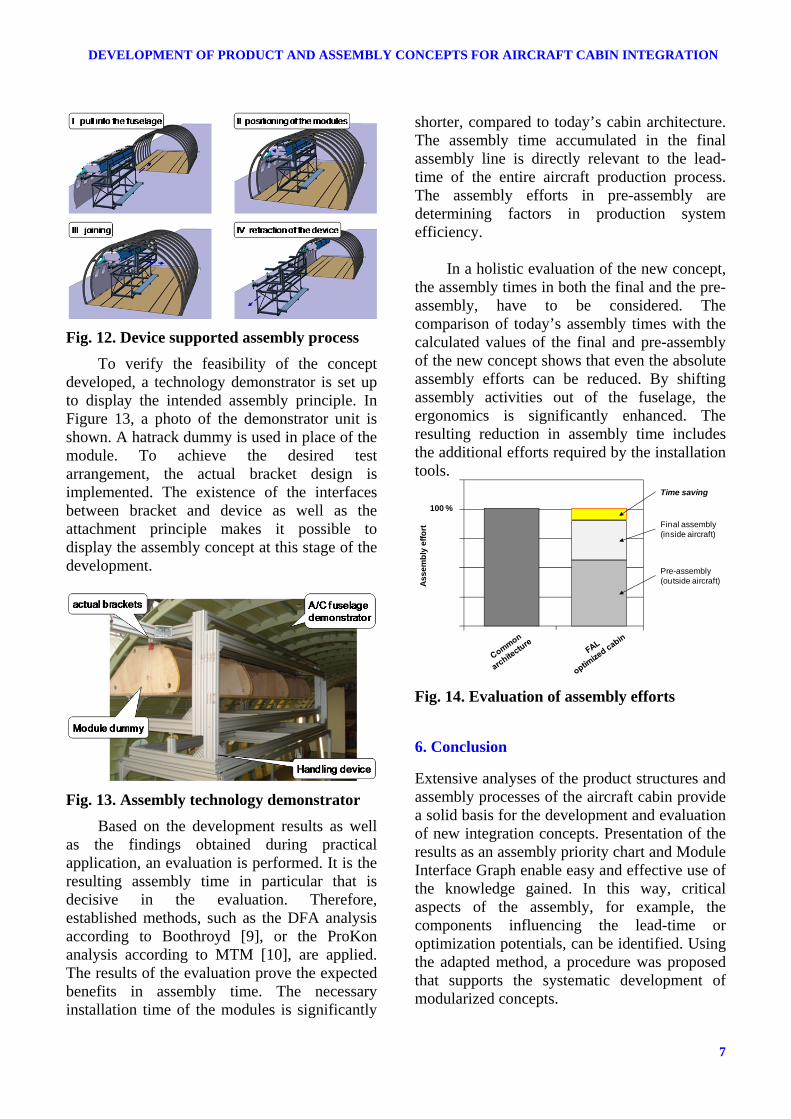
The device-based handling and mounting of the super modules requires extensive changes in the aircraft production process. To transport the modules into the fuselage, large- scale access is needed. In today’s assembly process, the interior is installed subsequent to the joining of all fuselage segments. The cabin components are carried manually through the passenger doors. Thus, their maximum size is limited. In the new concept, the fuselage is kept open, providing a large opening to perform cabin installation. Afterwards, the fuselage is closed by mounting the cockpit segment. A sequence of the device-based handling of the super modules and the mounting process is shown in Figure 12.
7
DEVELOPMENT OF PRODUCT AND ASSEMBLY CONCEPTS FOR AIRCRAFT CABIN INTEGRATION
Fig. 12. Device supported assembly process
To verify the feasibility of the concept developed, a technology demonstrator is set up to display the intended assembly principle. In Figure 13, a photo of the demonstrator unit is shown. A hatrack dummy is used in place of the module. To achieve the desired test arrangement, the actual bracket design is implemented. The existence of the interfaces between bracket and device as well as the attachment principle makes it possible to display the assembly concept at this stage of the development.
Fig. 13. Assembly technology demonstrator
Based on the development results as well as the findings obtained during practical application, an evaluation is performed. It is the resulting assembly time in particular that is decisive in the evaluation. Therefore, established methods, such as the DFA analysis according to Boothroyd [9], or the ProKon analysis according to MTM [10], are applied. The results of the evaluation prove the expected benefits in assembly time. The necessary installation time of the modules is significantly
shorter, compared to today’s cabin architecture. The assembly time accumulated in the final assembly line is directly relevant to the lead-time of the entire aircraft production process. The assembly efforts in pre-assembly are determining factors in production system efficiency.
In a holistic evaluation of the new concept,
the assembly times in both the final and the pre-assembly, have to be considered. The comparison of today’s assembly times with the calculated values of the final and pre-assembly of the new concept shows that even the absolute assembly efforts can be reduced. By shifting assembly activities out of the fuselage, the ergonomics is significantly enhanced. The resulting reduction in assembly time includes the additional efforts required by the installation tools.
Fig. 14. Evaluation of assembly efforts
6. Conclusion
Extensive analyses of the product structures and assembly processes of the aircraft cabin provide a solid basis for the development and evaluation of new integration concepts. Presentation of the results as an assembly priority chart and Module Interface Graph enable easy and effective use of the knowledge gained. In this way, critical aspects of the assembly, for example, the components influencing the lead-time or optimization potentials, can be identified. Using the adapted method, a procedure was proposed that supports the systematic development of modularized concepts.
100 %
Pre-assembly(outside aircraft)
Final assembly(inside aircraft)
As
se
mb
lye
ffo
rt
Time saving
Niklas Halfmann, Dieter Krause
8
Several concepts were developed and analyzed; key factors were identified. The degree of pre-assembly and the parallelization of processes are decisive in the final assembly line optimized cabin. The concept was advanced to a design and architecture that aggregates lining components and cabin systems into large modules. These modules are intended to be pre-assembled outside the fuselage then carried in by a handling device. The benefits lie in the reduction in lead-time and total working hours. The new architecture and the application of tool sets will be further enhanced. The concept creates a research opportunity in the field of automation. As already established in other industries, implementing automated processes in the cabin assembly environment is a major goal.
Acknowledgements
The content presented in this paper is based upon the results of joint research projects between Airbus Operations GmbH and the Institute for Product Development and Engineering Design at the Hamburg University of Technology. The projects are publicly funded by the Federal Ministry of Economics and Technology of Germany, as well as the Ministry of Economy and Labour Affairs of the Free and Hanseatic City of Hamburg. CAAM – Cabin Assembly and
Manufacturing CoCaM – Concepts for Cabin
Modularization ModIS – Modular Interior and System
Integration Kabtec – Cabin Technology for Comfortable
Passenger Platforms
References
[1] Andreasen, M.M., 1988, Design for Assembly, Springer-Verlag, London.
[2] Pahl, G., Beitz, 2007, W., Engineering Design, Springer-Verlag, Berlin.
[3] Blees, C., Krause, D., 2008, “On the development of Modular Product Structures: A Differentiated Approach”, International Design Conference – Design 2008, Dubrovnik, pp. 159-168.
[4] Blees, C., Jonas, H., Krause, D., 2009, “Perspective-Based Development of Modular Product Architectures”, Proceedings of the 17th International Conference on Engineering Design (ICED), Stanford, pp. 4-95-4-106.
[5] Erixon, G., 1998, Modular function deployment: a method for product modularisation, The Royal Institute of Technology, Department of Manufacturing Systems, Assembly Systems Division, Stockholm.
[6] Whitney, D.E., 2002, Mechanical Assemblies, Oxford University Press, New York.
[7] Krause, D. Gehm, M, Halfmann, N., 2009, “Visionary Integration Concepts for Aircraft Cabin Interior”, Proceedings of the 2nd International Workshop on Aircraft System Technologies, Hamburg, pp. 357-366.
[8] Krause, D., Gumpinger, T., 2008, “Lightweight optimization of an aircraft galley”, 3rd International Conference “Supply on the Wings”, Frankfurt/Main.
[9] Boothroyd, G., 2002, Product Design for Manufacture and Assembly, Marcel Dekker, New York.
[10] Deutsche MTM-Vereinigung e.V., 2006, Produktivitätsmanagement von Arbeitssystemen, Schäffer Poeschel, Stuttgart
Copyright Statement
The authors confirm that they, and/or their company or organization, hold copyright on all of the original material included in this paper. The authors also confirm that they have obtained permission, from the copyright holder of any third party material included in this paper, to publish it as part of their paper. The authors confirm that they give permission, or have obtained permission from the copyright holder of this paper, for the publication and distribution of this paper as part of the ICAS2012 proceedings or as individual off-prints from the proceedings.