Journal of Next Generation Technology (JNxtGenTech) Vol. 1, Issue 1, June 2021 29 The Effect of DPFC on Power Quality Improvement Using Hysteresis Band Pulse Width Modulation Veeramuthulingam. N 1 ,Rajan V.R 2 1 Research Scholar, Department of Electrical Engineering, Annamalai University, Chidambaram, Tamilnadu 2 Department of Electrical and Electronics Engineering, V V College of Engineering, Tirunelveli,Tamilnadu, India Email id: [email protected]1 , [email protected]Article Received: 1 Jan 2021 Article Accepted: 14 May 2021 Article Published: 29 Jun 2021 Abstract Hysteresis Band pulse width modulation (HB-PWM), this research provides a DPFC for increasing quality of power. The primary goal of in this study is to advanced a power flow control system that has low cost and the capacity as same in the UPFC controller but at higher reliability. The UPFC Controller is resultant model from the DPFC Controller, and the DPFC Controller has the same control ability as the UPFC Controller formation. The UPFC Controller formation is used to mitigate a power quality issue like voltage sag, swell. The series converters connect to many single-phase converters side finished line in the peculiar UPFC, the typical dc-link in DPFC Controller. The HB-PWM performance is proposed, which detects voltage sags and adjusts voltage of three single-phase reference DPFC. This paper suggested the structure is demonstrated by simulating the application of a DPFC controller in improving power quality in a Mat Lab environment. Keywords: DPFC, HB-PWM, Power quality I. Introduction The power system has become a particularly demanding subject in recent years due to increased load demand for power and the development of power system. There is a respectful commitment to keep power flowing in transmission lines while maintaining authenticity and speed [1]. The governance of power flow in the transmission system is handled by all flexible ac transmission devices. UPFC Controller is a FACTS system power flow controller that can manage transmission angle, bus voltage and line impedance [2]. For a bidirectional power flow system, the UPFC Controller is employed, which has both a converter like shunt and a series with a common DC link. Between the transmission line and the series converter, this converter series side injects voltage into the bus, causing by injection and absorption of real and reactive power. The current and voltage ratings of the devices utilised in Controller. The DPFC Controller, which is derived from the UPFC, is one of the FACTS family's most significant devices. The DPFC Controller, like the UPFC Controller, has the ability to control all of the limits inside the transmission bus network. The DC link between series and shunt, which is usually connected, is removed in the case of a DPFC Controller, and the DFACTS[3] theory is applied to the series converter depicted in Figure (a). The third order harmonic frequency of the real energy shift between the both converter like shunt and series converters. The Distributed FACTS concepts not only lower the ratings, but they also improve the system's authenticity and lower the cost of high voltage isolation. The following is the layout of the paper: The DPFC working principle is described in zone II. Zone III proposes a DPFC control discipline constructed on a hysteresis band pulse width modulation Citation Veeramuthulingam, N.,Rajan, V.R.(2021), The effect of DPFC on Power Quality Improvement Using Hysteresis Band Pulse width Modulation. Journal of Next Generation Technology, 1(1), 29-36.
Transcript
Journal of Next Generation Technology (JNxtGenTech)
Vol. 1, Issue 1, June 2021
29
The Effect of DPFC on Power Quality Improvement Using Hysteresis
Band Pulse Width Modulation
Veeramuthulingam. N1,Rajan V.R
2
1Research Scholar, Department of Electrical Engineering, Annamalai University, Chidambaram, Tamilnadu
2Department of Electrical and Electronics Engineering, V V College of Engineering, Tirunelveli,Tamilnadu, India
Article Received: 1 Jan 2021 Article Accepted: 14 May 2021 Article Published: 29 Jun 2021
Abstract
Hysteresis Band pulse width modulation (HB-PWM), this research provides a DPFC for increasing quality of
power. The primary goal of in this study is to advanced a power flow control system that has low cost and the
capacity as same in the UPFC controller but at higher reliability. The UPFC Controller is resultant model from
the DPFC Controller, and the DPFC Controller has the same control ability as the UPFC Controller formation.
The UPFC Controller formation is used to mitigate a power quality issue like voltage sag, swell. The series
converters connect to many single-phase converters side finished line in the peculiar UPFC, the typical dc-link
in DPFC Controller. The HB-PWM performance is proposed, which detects voltage sags and adjusts voltage
of three single-phase reference DPFC. This paper suggested the structure is demonstrated by simulating the
application of a DPFC controller in improving power quality in a Mat Lab environment.
Keywords: DPFC, HB-PWM, Power quality
I. Introduction
The power system has become a particularly demanding subject in recent years due to increased load
demand for power and the development of power system. There is a respectful commitment to keep
power flowing in transmission lines while maintaining authenticity and speed [1]. The governance of
power flow in the transmission system is handled by all flexible ac transmission devices. UPFC
Controller is a FACTS system power flow controller that can manage transmission angle, bus
voltage and line impedance [2]. For a bidirectional power flow system, the UPFC Controller is
employed, which has both a converter like shunt and a series with a common DC link. Between the
transmission line and the series converter, this converter series side injects voltage into the bus,
causing by injection and absorption of real and reactive power. The current and voltage ratings of the
devices utilised in Controller.
The DPFC Controller, which is derived from the UPFC, is one of the FACTS family's most
significant devices. The DPFC Controller, like the UPFC Controller, has the ability to control all of
the limits inside the transmission bus network. The DC link between series and shunt, which is
usually connected, is removed in the case of a DPFC Controller, and the DFACTS[3] theory is
applied to the series converter depicted in Figure (a). The third order harmonic frequency of the real
energy shift between the both converter like shunt and series converters. The Distributed FACTS
concepts not only lower the ratings, but they also improve the system's authenticity and lower the
cost of high voltage isolation.
The following is the layout of the paper: The DPFC working principle is described in zone II. Zone
III proposes a DPFC control discipline constructed on a hysteresis band pulse width modulation
Citation Veeramuthulingam, N.,Rajan, V.R.(2021), The effect of DPFC on Power Quality Improvement Using Hysteresis Band Pulse width Modulation. Journal of Next Generation Technology, 1(1), 29-36.
Journal of Next Generation Technology (JNxtGenTech)
Vol. 1, Issue 1, June 2021
30
method. In zone IV, the effect of the Distributed Power Flow Controller on power quality enrichment
is examined. Certainly, the simulation findings are evaluated in the final section of this paper.
II. Structure of the DPFC
The elimination of DC-links and the use of 3rd-current harmonic to active power exchange are the
fundamental problems in the DPFC principle. The operating principle of the DPFC is presented in
the following subsections.
Figure 1. shows the structure of a DPFC.
A. DC-Link Elimination and Power Exchange
Rather than using DC-link for power switching between converters, output and AC port of shunt
and series converters in the DPFC connect transmission line. The power swaps notion in DPFC is
based on the power concept of a non-sin component [9]. The sum of sin components at various
frequencies can be used to calculate non-sinusoidal component like voltage and current. It is the most
significant outcome of Fourier analysis. The active power is generated by the product of the current
and voltage mechanisms. The active power equation is as follows: Since the integral of some terms
with different frequencies is active power and zero, equation is as follows:
1
cosi i i
i
P V I
The current and voltage harmonic frequency, respectively, are Ii and Vi, and at the same frequency,
the angle formed by the foundation component of voltage and current. As seen in Equation 1, the
active powers at various frequencies are varied. As a result, the converter can exercise active power
while producing power at a different frequency. If the DPFC is used in a system with two bus
transmission lines; as a result, the power supply delivers true power and the shunt converter
consumes current at an elementary frequency. The Y-transformer is currently stuck at the third order
harmonic component.
The third order harmonic current is inserted into the -Y transformer's neutral via the output terminal
of the shunt converter. As a result, the harmonic current is increased in transmission line. This
harmonic current regulates the voltage of series capacitors. In the DPFC, active power is transported
between the two converter like shunt and series converters, as shown in Figure 2.
Journal of Next Generation Technology (JNxtGenTech)
Vol. 1, Issue 1, June 2021
31
B. The Merits of the DPFC
In comparison to the UPFC, the DPFC has a few merits: 1) High control capacity, The DPFC
Controller can coordinate all of the transmission network's line impedance, bus magnitude voltage
and parameters angle. 2) High reliability Series converter redundancy improves DPFC authenticity
throughout converter operation [10]. One of the series converters fails, the other will continue to
function. 3) It is a low-cost option. Single-phase converters have a very low rating when compared to
three-phase converters.
Furthermore, there is no requirement to link in line with the series converters in this composition due
to any voltage isolation. Series converters can be suspended using single-turn transformers. A case
study of using DPFC to reinstate UPFC of the KEPCO is explored to determine the applicability of
the DPFC. To attain the control capabilities as the UPFC, the DPFC structure employs less material
using same type of controller [9].
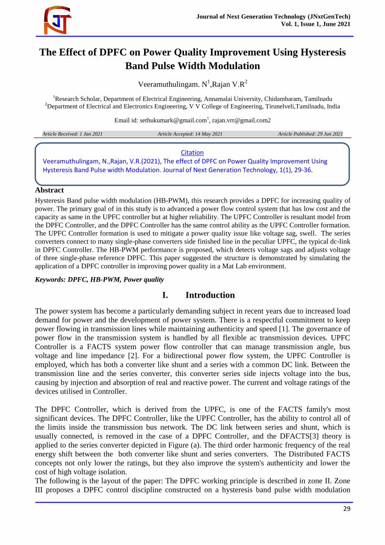
III. HB Pulse Width Modulation method for DPFC Control
As shown in Figure 3, the DPFC Controller has three regulator categories: shunt, central and series
control.
A: Central Control: This controller is in charge of all of the controllers, as well as the reference
signals that are sent to both shunt and series converter.
B: Series Control: The line's single-phase converters each have their own series control. The
controller inputs are the capacitor voltages, series voltage, and dq line current reference. A filter are
incorporated in every series controller to accurately represent fundamental and third harmonic
current. To catch frequency and phase data from the network, two single-phase phase lock loops
(PLLs) are worn [11]. Figure 4
C: illustrates a series controller's imagined schematic. Controlling Shunts: A three-phase converter is
coupled with a single-phase converter in a shunt converter.
Fig. 2. Power exchange between converters (DPFC).
Journal of Next Generation Technology (JNxtGenTech)
Vol. 1, Issue 1, June 2021
32
Figure 3: DPFC structure.
Figure 4: control structure with Series
Figure :5 (a) frequency shunt control (b) third-harmonic shunt control
Journal of Next Generation Technology (JNxtGenTech)
Vol. 1, Issue 1, June 2021
33
By drawing actual electricity at fundamental frequency from the grid, the three-phase converter
adjusts the capacitor's dc voltage between it and the single-phase converter. Figure 5 shows a block
diagram of the shunt control structure.
D. Proposed Determination and Detection Techniques
The HB Pulse Width Modulation methodology is presented as an identify and resolve tool to classify
voltage sags and regulate voltages of the DPFC. In the pre-sag state, the grid's line-to-neutral
voltages are
, , , (2)ref ref
dpfc d grid d grid dV V V
, , , (3)ref ref
dpfc q grid q grid qV V V
Where ,
ref
dpfc dV and ,
ref
dpfc qV are the reference component of DPFC desired interject voltages in the
HPWM, appropriately
Figure 6. DPFC Simulation model
As the first step in this methodology, I was converted from an abc correlative system to an SRF
(dq0). After that, the actual and reference line-neutral grid voltages' dq0 values are compared, and
the presence of a discrepancy indicates voltage sag, and the DPFC desired target voltages' dq0 values
are evaluated.
Iv. Power Quality Improvement
As shown in Fig. 6, this design was created in the Matlab/Simulink environment. A supply voltage is
coupled to a non-linear in this system simulation. Table 1 contains the simulation parameters. This
supply is connected to the load via the transmission lines system 1 and 2 as well as the correlative
transmission lines. The length of the correlating transmission lines is the same. Transmission line 2
has a built-in DPFC. The different loads are coupled to analysis good performance. To do a transient
analysis, the fault system must be connected to the load. A Y-three-phase transformer connects the
shunt converter three phase system to transmission line 2 in parallel, and series converters connect
series with are distributed throughout the line.
Journal of Next Generation Technology (JNxtGenTech)
Vol. 1, Issue 1, June 2021
34
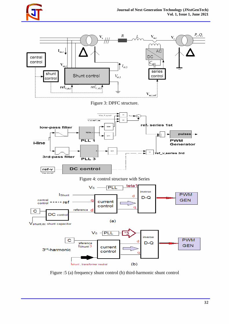
V. Simulation
The conclusions of this case study, which considers swell/ sag state in a the following are the
components of a single infinite bus system. As seen in Figure 6, there is a failure near the system
load, is created to assess voltage drop. This problem has a duration of 0.5 seconds (500-1000 ms). As
seen in Figure 7, a three-phase fault causes measurable voltage to drop. The voltage per unit is
around 0.5. The DPFC is capable of successfully compensating for load voltage sag. Figure 8 depicts
the reduction of voltage sag using a DPFC Controller. Figure 9 shows the 1.1 per unit swell after the
three-phase fault is introduced.
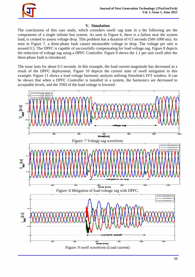
The issue lasts for about 0.5 seconds. In this example, the load current magnitude has decreased as a
result of the DPFC deployment. Figure 10 depicts the current state of swell mitigation in this
example. Figure 11 shows a load voltage harmonic analysis utilising Simulink's FFT window. It can
be shown that when a DPFC Controller is installed in a system, the harmonics are decreased to
acceptable levels, and the THD of the load voltage is lowered.
Figure: 7 Voltage sag waveform
Figure: 8 Mitigation of load voltage sag with DPFC.
Figure: 9 swell waveform (Load current)
Journal of Next Generation Technology (JNxtGenTech)
Vol. 1, Issue 1, June 2021
35
Figure: 10 swell with DPFC (load current)
Figure: 11 THD (The load voltage)
Table I: Parameter
Parameters Values
Voltage 230kv
Power 100mw
/ Frequency 50hz
X /R 3
Inductance/Capacitance Reactance 0.12/0.12 Pu/Km
Length of Transmission Line 100 Km
Short Circuit Capacity 11000 Mw
Resistance 0.012 Pu/Km
VI. Conclusion
In the power industry, improving the power quality of transmission line is a critical problem. In this
study, the usage of DPFC controller as a new flexible ac transmission systems device is simulated in
the Matlab/Simulink environment to improve the voltage Swell and Sag of a structure composed of a
source coupled to a non-linear load through nearby transmission lines. The voltage dip is
investigated using a three-phase failure close to the system load. The Hysteresis Band pulse width
Journal of Next Generation Technology (JNxtGenTech)
Vol. 1, Issue 1, June 2021
36
modulation approach is utilised as an exposure and resolved approach to notice the Sags and Swells
and establish the reference voltages of the DPFC Controller. The achieved simulation results
demonstrate the performance of the DPFC Controller in totally mitigating swell and sag and
improving power quality system.
References
[1]. J. Faiz, G. H. Shahgholian, and M. Torabian, “Design and simulation of UPFC for enhancement of power
quality in transmission lines,” IEEE International Conference on Power System Technology, vol. 24, no.
4, 2010.
[2]. A. E. Emanuel and J. A. McNeill, “Electric power quality,” Annu. Rev.Energy Environ, 1997.
[3]. I. N. R. Patne and K. L. Thakre “Factor affecting characteristics of voltage sag due to fault in the power
system,” Serbian Journal of Electrical engineering. vol. 5, no.1, 2008.
[4]. J. R. Enslin, “Unified approach to power quality mitigation,” in Proc.IEEE Int. Symp. Industrial
Electronics (ISIE ’98), vol. 1, 1998.
[5]. B. Singh, K. Al-Haddad, and A. Chandra, “A review of active filters for power quality improvement,”