MINISTRY OF AVIATION R. & M. No. 3332 AERONAUTICAL RESEARCH COUNCIL REPORTS AND MEMORANDA The Effect of Solar Radiation Pressure on the Attitude Control of an Artificial Earth Satellite By N. E. IvEs, B.Sc., A.Inst.P. LONDON: HER MAJESTY'S STATIONERY OFFICE x963 PRICE I2S. 6d. NET
Transcript
M I N I S T R Y OF A V I A T I O N
R. & M. No. 3332
A E R O N A U T I C A L RESEARCH C O U N C I L
REPORTS AND MEMORANDA
The Effect of Solar Radiation Pressure on the Attitude Control of an Artificial Earth Satellite
By N. E. IvEs , B . S c . , A . I n s t . P .
L O N D O N : HER MAJESTY'S S T A T I O N E R Y O F F I C E
x963 P R I C E I 2 S . 6d. N E T
The Effect of Solar Radiation Pressure on the Attitude Control of an Artificial Earth Satellite
By N. E. IVES, B .Sc . , A . I n s t . P.
COMMUNICATED BY THE DEPUTY CONTROLLER AIRCRAFT (RESEARCH AND DEVELOPMENT),
1V~INISTRY OF AVIATION
Reports and Memoranda No. 3332* April, z96±
S u m m a r y .
This report presents an account of the demand made by solar radiation pressure 6n the attitude-control system of an earth satellite whose external configuration is in the shape of a rectangular prism, the surfaces
being assumed to be perfectly reflecting. Expressions determining the amount of angular impulse that must be supp~ed by an attitude-control system in the course of a year in order to provide perfect stabilisation for a space-stabilised satellite, and an earth-pointing satellite in a non-precessing orbit, are developed. Examples are given for particular cases and further examples include a comparison of the radiation-pressure torque with the torque set up by the earth's gravitational field, and the attitude deviations arising as a result of radiation pressure on an earth-pointing satellite employing gravity-gradient stabilisation alone.
S e c t i o n
1.
2.
3.
4.
.
.
.
L I S T OF C O N T E N T S
Introduct ion and General Discussion
Assumptions
Radiation Pressure on a Perfectly Reflecting Rectangular Prism
The Space-Stabilised Satellite
4.1. Amount of angular impulse per year
4.2. Numerical example Oil amount of angular impulse
4.3. Development of a nett amount of angular impulse
T h e Earth-Pointing Satellite in a Non-Precessing Orbit
5.1. Amount of angular impulse per satellite orbit
Attitude Deviations of Earth-Pointing Gravity-Gradient-Stabil ised Satellite due to
Radiation Pressure
A Comparison of the Torque due to Radiation Pressure and the Earth 's Gravitational
Field for a Space-Stabilised Satellite of Given Orientation
Radiation falling on a surface may be partly absorbed, partly reflected and, unless the body be
very thick or opaque, partly transmitted. Assuming no transmission, any surface may be specified
by its reflectivity or absorptivity, the former being the fraction of the radiation incident on the
surface which is reflected and t h e latter the fraction which is absorbed. A surface having an
absorptivity of unity for all wavelengths is called an 'ideal' black surface. In general, the absorptivity
varies greatly with wavelength and, "to a lesser extent, with the temperature of the absorber.
T h e amount of the sun's radiant energy in the vicinity of the earth is generally expressed in terms
of the solar constant, this being the amount of the sun's radiation received on unit area in unit time,
the receiving area being perpendicular to the sun's rays and at a distance from the sun equal to the
mean radius of the earth's orbit. The solar constant S ' may be expressed as 1.94 cal cm -~ rnin -1
or 1.3 × 10⁶ erg cm -~ sec -I. If the radiation is completely absorbed by the body then 1.3 × 10⁶ ergs
will be absorbed by 1 cm ~ every second. In accordance with Einstein's energy-mass relationship
(E = mc 2 where c is the velocity of the radiation) the mass associated with a unit erg of radiation
2
is 1/c 2 so that the momentum imparted to unit area per second is cS'/c 2. Thus, taking
c = 3 x 101° cm sec -1, the radiation pressure due to radiation at normal incidence on a completely
absorbing body in the vicinity of the earth is
p _ S ' 1.3 x l0 G
c 3 × 10 l° - 4.3 x 10 -5 erg cm -s ,
i.e. P = 4" 3 x 10 -~ dynes/cm °"
since erg cm -3 - dyne cm -2.
In the F.P.S. system of units, P = 2 .9 x 10 -6 pdl/ft ~. Radiation pressure will be capable of producing a torque about the centre of mass of an orbiting
earth satellite. The magnitude of the radiation-pressure torque will be influenced by the nature
of the satellite's surface, i.e. whether the surface reflects or absorbs most of the radiation. Bombard-
ment by cosmic dust (micrometeorites) will inevitably produce a gradual erosion of the outer
metallic skin of the satellite, similar to the erosion of a metal by the impact of high-speed molecules.
This report presents an analysis of tile effect of the sun's radiation pressure on the attitude control
of a satellite in the shape of a rectangular prism and whose surfaces completely reflect the radiation
incident on them; both space-stabilised and earth-pointing satellites are considered. Although the
theory is carried out specifically for the rectangular-prism configuration, the method can be
generalised to allow corresponding theoretical deductions to be made for many of the more
charactg~istic satellite configurations, for example cylinders, spheres and cones. Whenever curved
surfaces are involved in the calculations the effective areas presented to the sun must be used in
any theoretical analysis, and it is perhaps best to carry out the analysis for a given configuration
rather than at tempt a more general t reatment to cover a range of configurations. Alternatively, the
results for the rectangular prism may be used as an approximation for the sphere or cylinder if, as
may well be the case, very accurate estimates are not required. Simple calculations will show tile
order of the error that may be expected by employing such an approximation. A detailed analysis of tile more general problem of absorption and reflection at the satellite's
surface proves to be more complex than the analysis for a completely reflecting surface. In the latter
case only the normal compohent of the force due to radiation pressure on a given surface need be
considered, whereas in the case of. a 'black body ' surface the force on the surface will be in the
direction of the incident radiation, and has therefore a tangential component as well as a normal
component of force. A further complication may arise as a result of re-radiation from a surface
at a given temperature; if the surface acts as a diffuse emitter, i.e. emits radiation uniformly in all
directions, there will be a reaction on the surface along the direction normal to the surface. However,
such considerations have not been included in the present work, which is restricted to the case
of complete reflection. As defined in Ref. 1, 'earth-pointing' satellite generally refers to a satellite whose principal axis
about which the moment of inertia is least points continually towards the centre of the earth;
the earth's gravitational field provides a stabilising effect for attitude motion about the other two
principal axes. However, for relatively large orbital radii, when the stabilising effect may be very
small, it may still be desired to have one axis continually pointing at the ear th- -and such a satellite
would still be an earth-pointing satellite even though a built-in atti tude-control system would
probably be required to achieve this.
3 A2
(87419)
2. Assumptions.
(1) The sun's radiation is the only source of attitude perturbation acting on the satellite.
(2) The magnitude of the solar radiation pressure in the vicinity of the earth is constant for all positions of the earth along its orbit.
(3) The satellite's surface is homogeneous and has a reflectivity of unity.
(4) Translational motion of the satellite relative to the earth is neglected, so that the intensity of the radiation in the vicinity of the satellite is taken to be constant and equal to that amount defined by the solar constant.
(5) Eclipses of the satellite as it passes through the earth's shadow are neglected so that the satellite
is regarded as being continuously under the influence of the radiation. The expressions developed in the text for the amount of angular impulse will therefore represent maximum values. The actual
values will clearly depend on the amount of time spent by the satellite in the earth's shadow; for example, if the satellite spends half of its time in the shadow, the angular impulse will be approxi-
mately half the corresponding maximum value. If the control system is designed to provide this maximum angular impulse it will be capable of providing compensation at all times, irrespective of the changing shadowing effect due, for example, to orbital regression.
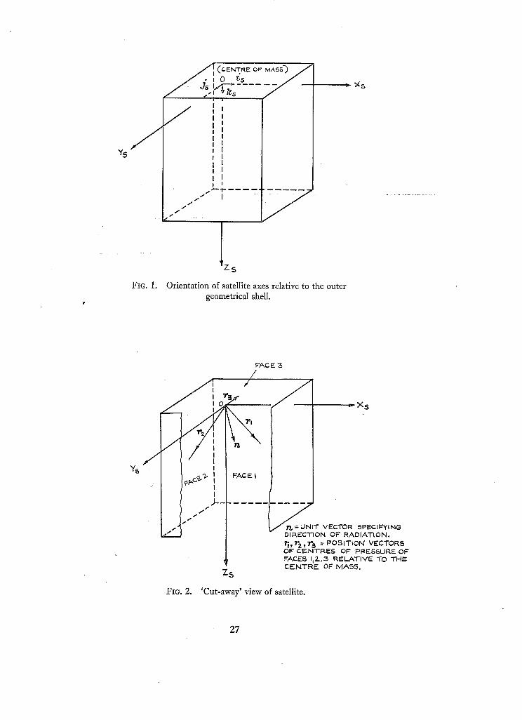
(6) Attitude control will in general be pro,(ided about the principal axes of inertia of the satellite, but the theory presented in this report applies to any systems of orthogonal right-handed axes (origin at the centre of mass of the satellite) assumed to be rigidly embedded in the vehiclg ~.
It will be assumed that the chosen axes lie along directions parallel to the faces of the satellite so that each pair of axes lies in a plane parallel to two surfaces of the configuration (Fig. 1).
Assumptions (4) and (5) applied to the case of the space-stabilised satellite reduce the problem to an investigation into the effect of solar radiation pressure on the attitude control of a space- stabilised body following the same orbit round the sun as that of the earth. In the case of the earth-pointing satellite (in a non-precessing orbit) the problem reduces to a similar investigation for a body spinning about an axis whose direction remains fixed in space.
3. Radiation Pressure on a Perfectly Reflecting Rectangular Prism.
By assumption (6) it follows that the normal passing through the centre of pressure of a given surface is along a direction parallel to one of the satellite axes. As the satellite is carried round the sun by the earth the direction of the sun will change relative to the surface geometry of the satellite, the only exception being a satellite which continually points the same surface towards the sun.
Let X Y Z be an orthogonal right-handed system of axes (origin at the centre of mass of the satellite) having a fixed orientation in space, and let n be the unit vector specifying the direction of the sun's radiation relative to these axes. Let [cos 7x, cos Yz~, cos 7z] be the direction cosines such that
n = cosyx i + cos 7j~ j + cos y z k (1)
where (i, j, k) are unit vectors along X, Y, Z respectively.
Let Xs, Ys, Zs be a similar system of axes representing satellite axes, with (is, Js, ks) unit vectors along Xs, Ys, Zs. Suppose, for the present, that satellite axes are coincident with X, Y, Z and let Sxs~s , S~:szs and Sysz s be the surface areas parallel to the planes containing the Xs, Ys; Xs, Zs; and Ys, Zs axes.
Consider radiation incident on face I of area Sxszs--Figs. 2 and 3. The incident radiation is at an angle y:z with the surface normal and so, assuming complete reflection at the surface, the force
exerted on this surface is
F = 2PSxsz s cos~y~js (2)
where P is the radiation pressure on a 'black body' surface placed at right angles to the direction
of the radiation. The normal component given by equation (2) is proportional to cos2yg because
of the obliquity of the radiation on the surface as explained in Appendix II. The torque about the centre of mass due to this force component is
L1 = r l x F (3)
where rl = (X l i s+y j s+z~ks ) is the position vector of the centre of pressure of face 1 relative to
the centre of mass,
i.e. L1 = 2PSxsz s cos~yF(xlks- z l i s ) . (4)
Since the force is normal to the surface, the torque acting about the centre of mass, due to radiation
incident on the face opposite to face 1 must be exactly the same as if the radiation was supposed
incident on the inner side of face 1. Hence, if the force given by equation (2) is written as
F = 2PSxszslCOS y r l cos Ys~ j,~ (5)
then this equation represents the magnitude and the direction of the force for all yy . If l cos YY [cos Y~
is written instead of cos2y~- in equation (4) then this equation represents the torque for all YY,
since the torque-arm components entering into the equation are the same whether the radiation is
incident on face 1 or the opposite face. Thus,
LI = 2PSxszsl cos ~,y I cos r r (x,ks- z,i~). (6)
A similar argument applies for radiation incident on the other two pairs of faces giving tl~e torque components
L~ = 2PSysz, s I cos Yx [cos Yx (z2Js-Y2ks) (7)
due to radiation incident on face 2 or the opposite face, and
L 3 = 2P&zsj~s[ cos r z [ cos r z (Yai,s- xajs) (8)
due to radiation incident on face 3 or the opposite face. The torque-arm components in the latter two equations are the components defined by the
position vectors r 2 = (x2i s +Y2Js + z2ks), r3 = (xais +Yajs + zak,s) representing the positions of the centres of pressure of faces 2 and 3 relative to the centre of mass, Fig. 2. The directions of the
satellite axes relative to three faces of the configuration can always be chosen to make the torque-arm components entering equations (6), (7) and (8) positive quantities, and all torque-arm components
will be regarded as positive throughout the remairLder of this report. The resultant torque about the centre of mass may be written
r = 2 P [ ( y a S x j s ] cos YzI cos yz - z~Sxszs[ cos yx~ [cos y . ) i s +
+ ( ~ s r , ~ , l cos r~ lcos r~ - ~ s ~ [ cos r . I cos rz)Js +
+ (xtSxszsl cos r r [cos y r - y2Srszs[C°S yx]COS 7x)ks]. (9)
5
I f any changes in the directions of the satellite axes, and any shifts in the position of the centre
of mass relative to the fixed surface geometry of the satellite are neglected, the radiation-pressure
torque will vary only as the direction cosines vary. For a space-stabilised satellite the change in
the direction cosines will be due to the satellite's motion about the sun; in the case of an earth-
pointing satellite, i.e. one which points the same axis continually towards the centre of the earth,
the torque components will also vary as a result of the changing orientation of the satellite as it
revolves around the earth.
4. The Space-Stabilised Satellite.
Certain theoretical investigations which follow require integrations along the path described by
the earth in its journey round the sun, and to perform such integrations it is convenient to express
the radiation-pressure torque in terms of the angle 0 measured in the plane of the ecliptic, 0 being
zero when the earth is at perigee. Let X' , Y' , Z ' define a system of space-fixed axes with Z' perpen-
dicular to the plane of the ecliptic and X ' and Y' along the major and minor axes respectively of the
orbit followed by the earth in its path round the sun, the axes having origin at the centre of mass
of the satellite (Fig. 4). Let ( i ' , j ' , k') b e u n i t vectors along X' , Y', Z ' and have direction cosines
[(l 1, m 1, nl); (12, m2, nz); (18, ma, n~)] relative to axes X, Y, Z. Then, since satellite axes are coincident with X, Y, Z,
i ' = l l i s + mlj s + nlk ~
j ' = 12is + m2js + n~ks (10)
k' = l~i s + majs + naks.
Relative to the two sets of axes,
n = cos Yx is + cos Yr Js + cos Yz k,s (11)
n = cos 0i' + sin 0j' (12)
since n moves in the plane of the ecliptic and 0 defines the angular position in the ellipse as indicated in Fig. 4. Combining (10) and (12) we have
n = ( l~ is+mljs ,+nlkv) cos 0 + ( 1 2 i s + m j s + n 2 k s ) sin 0,
i.e. n = (l I cos 0 + l~ sin 0)i s + (m~ cos 0 + m 2 sin O)j s + (n 1 cos 0 + n~ sin O)k s . (13)
Equating coefficients of is, Js, ks in equations (11) and (13) gives the relations
c o s y x = l l c o s 0 + l 2 s i n 0
c o s y r = ml cos 0 + m 2 sin 0 J (14)
cos Yz = nl cos 0 + u~ sin 0.
T h e torque due to radiation pressure may therefore be written, using (9) and (14),
r = 2P[yaS~czrslnl cos 0 + u 2 sin 0[(n t cos O+n 2 sin 0) -
- z lSxs z , s [ml cos 0 + N2 sin Ol(m 1 cos O+m 2 sin 0)]i s +
+ 2P[zzSr~zs l lx cos 0 + lu sin 01(h cos 0+z sin 0) -
- x a S x s r s ] n 1 cos 0 + n.z sin O](n~ cos O+n 2 sin 0)]js +
+ 2P[xiSxzz~]m~ cos 0 + m2 sin O](m t cos O+mz sin 0) -
- y ~ S r s z s l h cos 0 + l~ sin 0I( h cos 0+ l 2 sin 0)]k~. (15)
6
4.1. Amount of Angular Impulse per Year.
T he amount of angular impulse required from the attitude control in order that the satellite
shall remain completely space-stabilised throughout one year may be determined by summing the
angular impulses required to maintain each of the satellite axes in the desired direction throughout
the year; satellite axes are chosen since the atti tude-control torques are assumed to be provided
about satellite axes. The total amount of angular impulse per year is therefore
F F 0=0 0=0 0=0
where (P 1, Pz, P3) are the components of r along (i s, is , ks)-
Taking each component in turn,
(16)
Let
and
and write
r l (0) = 2 P [ y a S x s r s l n ~ cos O + nz sin OI(n 1 cos O+n 2 sin 0) +
+ z l S x s z s [ m l cos 0 + mz sin O[(ml cos 0 + m 2 sin 0)].
f~(O) = n l cos O + n 2s in0
f,~(O) = m 1 cos 0 + m2 sin 0,
hi ~ = y a S x s r s , k~ 2 = z lSx~.Zs ,
then the expression for the torque component becomes
FI(0) = 2P [k~[ f~(0) ]f,~(0) - h~lf,~(O) [/,~(0)]. I f
Consequently, 121(0 ) is zero only when klf~(O ) - k,L~(O ) = 0 giving
[ k l n l - k ~ m l l 0 tan -1 \ k~m~-k ln~ / + N%r (17)
where N ' is an integer or zero. Hence, as 0 increases over a range of 2~, I~1(0) will be zero when 0 = 01' and 0 = 01 ' + ~r,
where 01' is the value given by equation (17) with N ' = 0. Therefore
Irl(0)l dO = rl(0) d o - r (0) d o . ( is) ' o=o J0=01" d0 Jo=ol"+- ~ I
Similarly, F2(0 ) is zero when ka.~(O ) - kJ~(O) = 0 w h e re , (0 ) = / i cos 0 + l 2 sin 0, ha ~ = z 2 S r s z s and k4 z = x ~ S x s r s , giving P2(0) zero when
(kal 1 - k4n 1 0 = tan -1 ~ ~ / + N%r. (19)
Again, Pa(0) is zero when kJ,,(O)- kJ~(O)= 0 where ks~= x, Sxszs and k ~ = y2Syszs , giving Pa(0) zero when
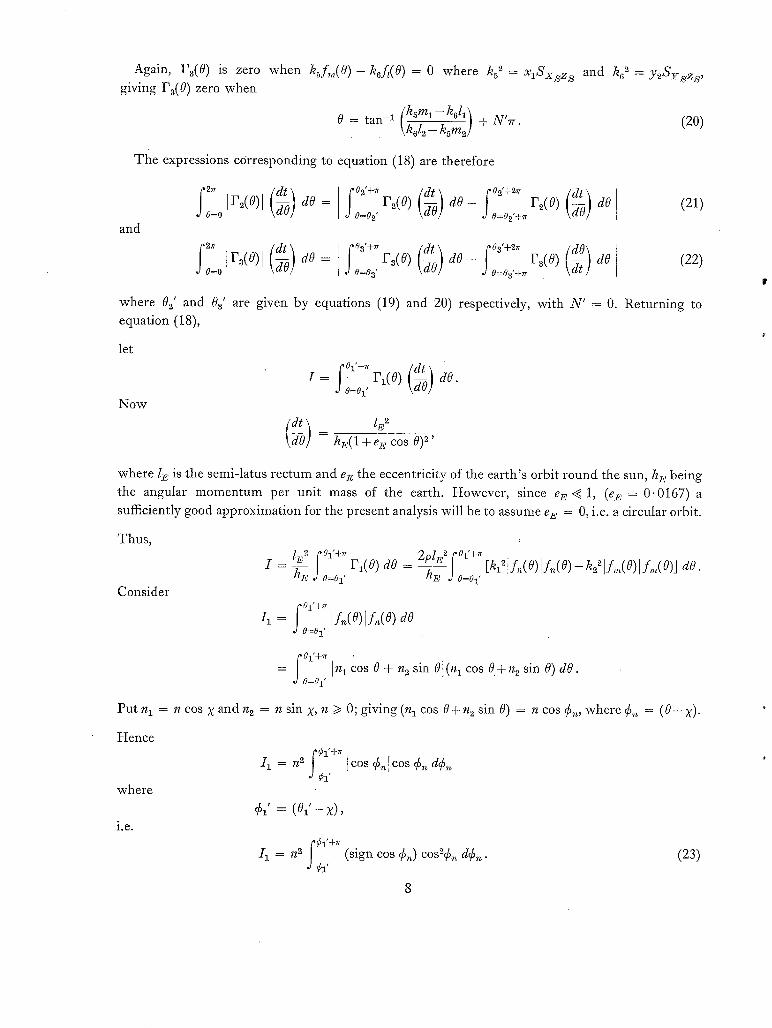
The expressions corresponding to equation (18) are therefore
and
Ir~(o)l 7o do = [ r~(o) d o - f F~(0) dO (21) o=o .o=o¢ ~ .o=o~,+~ 2-~
j'z'~ (dr ) ] °a'+" (dr) oa'+2,~ (dO) Iv~(o)l 7o dO= ~ r~(0) d O - ~ va(o ) dO (22)
o=o .3o=oa' 7o .3o=oa'+,~ &-
where 0=' and 0 a' are given by equations (19) and 20) respectively, with N ' = 0. Returning to equation (18),
let
Now
, 0 1 ' + r r
, : 7O = h~:(l+et~ cos O) ~'
dO.
where l E is the semi-latus rectum and e~ the eccentricity of the earth's orbit round the sun, hi,: being the angular momentum per unit mass of the earth. However, since e E ~ 1, @1,: = 0.0167) a
sufficiently good approximation for the present analysis will be to assume e E = 0, i.e. a circular orbit.
Thus,
Consider
I = ~ .30:0; P,(O) dO - h~, .3o-o~, [k:=]I"(o)IL(o)-&'V"(o)I:'(o)] ao.
f 01"+rr 11 = I fde)] f ,~(o) dO
,)0=01'
~ 01'+7r = In, cos O + n~ sin 0I(n , cos e + n2 sin O) dO.
.30=01"
Put n,
Hence
where
i.e.
= n cos X and n2 = n sin PC, n >/0; giving (n 1 cos 0+n~ sin 0) = n cos ¢,,, where ¢,, = ( 0 - PC).
i , = : lcos ¢~lcos ¢,, a¢,~ ,J95 * '
¢,' = ( 0 , ' - x ) ,
f ¢l'+rr
I 1 = n 2 (sign cos ¢~) cos2¢,,, d¢~. J¢, '
(23)
I f ¢,~ is considered to lie in the range - ~r/2 < ¢~ ~< 3rr/2 then
11 11' rt 2 (sign cos ¢1') c°s=¢~ d¢,~ - (sign cos ¢1') c°s2¢,, d¢~ \ '1 ¢1' drd~
i f - rr/2 < ¢1' < ~r/2, since (sign cos ¢,,) changes when ¢,4 = rr/2,
i.e.
• / (.Tr12\d ~¢1'+,v ) 11' = n2(sign cos ¢1') / / ¢ ( cos"¢,, - ,, c o s % , d e , , ,
( /1' = - n~(sign cos ¢1') ¢1' + - •
I f rr/2 < ¢1' < 3~r/2, the integral is
giving
= = ( F r ) /1 I1" n~ (sign cos ¢1') c°s~¢,~ d¢.,~ - (sign cos ¢i ') c°s2¢~ d¢~ ""] ¢:t' d-rr/2
since (sign cos ¢~) Changes when ¢,~ = 3rr/2.
I f we wri te ¢1' = ¢1" + ~r, then since 7r/2 < ¢1' < 37r/2, ¢1" must lie in the range - ~/2 < ¢1" < 7r/2.
T h e integral becomes
(F ? ) I1" = n 2 sign cos (¢1"+ rr) cose¢~ de,, - sign cos (¢1" + ~r) cos2¢,, de,, . \ O ¢ l " + r r -rr/2
This may be wri t ten
/1" = - n2 (sign cos ¢1") \o01" 0~'2
Hence /1" is s imply equal to - 1 1 ' wi th ¢1' replaced by ¢1". ¢1" [defined in the open interval ( - rr/2, ~r/2)] is, of course, s imply the value of ¢~. in this interval corresponding to Pl(0) = 0
so that when ¢1' lies in the range rr/2 < ¢ 1 ' < 3rr/2 the integral ,nay be taken be tween limits
(¢1'-~r) and ¢1' and the sign of the integral reversed. A general expression for the integral may
therefore be wr i t ten
where 961 is defined in the range - rr/2 < ¢1 < rr/2, ¢1' in the range - rr/2 < ¢1' < 3rr/2, excluding
¢1' = ~r/2, and ¢1 = ¢1' if ¢1' falls in the range - ~r/2 < ¢1' < rr/2 or ¢1 = ¢1' - ~r if ¢1' falls in the
range rr/2 < ¢1' < 3Tr/2.
I f ¢1' = - ~r/2, equat ion (23) gives
= ~7r12 I 1 n 2 (sign cos ¢~) cos2¢,~ de,, , (25)
O-a/2
i.e. 11 = n2rr/2 since cos ¢~ remains positive th roughou t the integration. Similarly, if ¢1' = rr/2,
I1 = - ~z~r/2 since cos ¢,~ is now always negative.
f 01"+lr
Treating 12 = [f,~(0) If,,~(0) dO in a similar manner, with n h = m cos ¢ and m 2 = m sin ¢, dO=O 1,
m /> 0 and Cm = (0 -¢ ) , ¢~' = (01 ' -¢) with ¢2' restricted to the range - ¢r/2 < ¢~' < 3~r/2 and excluding Ca' = ~r/2, then
I 2 = - m~(signcos¢~') (¢2 + s i n : ¢ ~ ) (26)
with ¢2 and ¢2' defined in a similar manner to ¢1 and ¢i' in equation (24). When applying these results it is probably better to evaluate the integrals separately and then determine I = I 1 - I ~ , rather than combine the two integrals and then perform a numerical substitution.
Since the integral of the ]21(0 ) function over a complete cycle is zero, then
The analysis for J2 and Ja and the results will merely be
4PIE ~
w h e r e / , = -/2(sign cos Ca') (¢3 + ~ )
with the relations 11 = I cos s e and l~ = l sin ~:, .1/> 0, ¢~' = ( 0 2 ' - ~ )
and
I~ = ~n~(signcos¢4 ') (¢,~+ _ s ~ ) ,
J3- 4PIE~ • - I(k 4-kg-r°)l
hE ](k12Ii-k2212) (27)
are given by equations (24) and (26) and J1 = Irl(°)l ~0 dO. 0=0
follows exactly the same line of argument as that presented for Jt stated.
where
and
I 5 = -m2(s ignc°s¢5 ' ) , ( ¢ 5 + ~ ) ,
(28)
with ¢4' = (02'- X).
(29)
with ¢5' = (02'- ¢)
16= -/2(sign cos 66') (¢6 + ~ ) , with 66' = (0a ' -~) .
The angles ¢a', ¢4', 65', ¢6' are defined in the same range as 61' and ¢2' and the integrals should be treated exactly as 11 and 12 in the detailed theory.
Substitution of J1, Je, Ja into equation (16) allows a determination of the total amount of angular impulse per year which would be necessary to keep the satellite completely space-stabilised when under the continuous influence of the sun's radiation. However, as the satellite may spend almost half of its time in the earth's shadow, equation (16) will represent an upper estimate of the quantity under discussion.
10
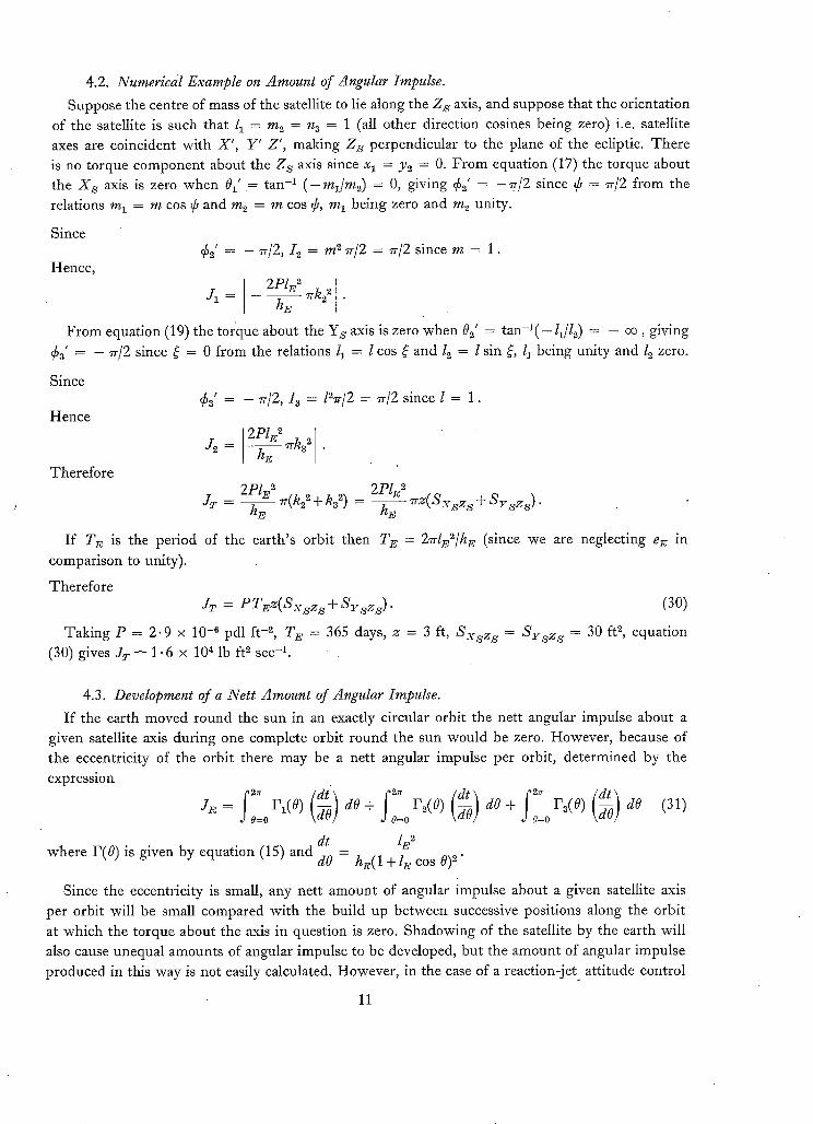
4.2. Numerical Example on Amount of Angular Impulse.
Suppose the centre of mass of the satellite to lie along the Z z axis, and suppose that the orientation
of the satellite is such that /1 = m 2 = n 3 = 1 (all other direction cosines being zero) i.e. satellite
axes are coincident with X' , Y ' Z' , making Z z perpendicular to the plane of the ecliptic. The re
is no torque componen t about the Z S axis since x 1 = Y2 = 0. F r o m equation (17) the torque about
the X s axis is zero when 01' = tan -1 ( - m l / m 2 ) = 0, giving ¢2' = -Zr/2 since ~ = 7r/2 f rom the
relations m 1 = m cos ~ and m~ = m cos ¢, m 1 being zero and m 2 unity.
Since
Hence, ¢ ( = - 7r/2, I e = m e rr/2 = ~r/2 since m = 1.
2P/z e
J l = - h ~ ~k'~2 " I
From equation (19) the torque about the Ys axis is zero when 0 2' = tan-~( - l~/12) = - oo, giving
¢ 3 ' = - ~r/2 since ~ = 0 f rom the relations 11 = I cos ~: and l 2 = l sin ~:, l~ being unity and l 2 zero.
Since
Hence
Therefore
8 t
J 2 = ~ , ~ k a 2 •
2PlE 2 J r - ~ (k2~ + k~ ~) = - -
hE
= - zr/2, I a = lez/2 = 7r/2 since l = 1.
2P1F, ~ hE ~ z ( S x s z s + S r z z s ) "
I f TE is the period of the ear th 's orbit then T E = 2z@,2/hE (since we are neglecting e~ in
comparison to unity).
Therefore
JT = P T E z ( S x s z s + S r sz~;) " (30)
Taking P = 2 .9 x 10 -G pdl ft -2, T~. = 365 days, z = 3 ft, S x s z ~ = S y s z s = 30 ft 2, equation
(30) gives J r --~ 1.6 x 10⁴ lb ft 2 sec -1.
4.3. Development of a Net t Amount of Angular Impulse.
I f the earth moved round the sun in an exactly circular orbit the nett angular impulse about a
given satellite axis during one complete orbit round the sun would be zero. However , because of
the eccentricity of the orbit there may be a nett angular impulse per orbit, de termined by the
expression
5 JR = 0=0rl(°) gO ao+ 0=0r2(°) go do+ 0:0r3(°) gO ao (31)
dt lE 2 where P(0) is given by equation (15) and d-0 = hE(1 + l• cos 0) 2.
Since the eccentricity is small, any nett amount of angular impulse about a given satellite axis
per orbit will be small compared with the build up between successive positions along the orbit
at which the torque about the axis in question is zero. Shadowing of the satellite by the earth will
also cause unequal amounts of angular impulse to be developed, but the amount of angular impulse
produced in this Way is not easily calculated. However , in the case of a react ion- je t att i tude control
11
system any such net t build up is irrelevant since it is s imply the result of ejecting gas which provides
the compensa t ing torque . Other systems involving, perhaps react ion-wheels should be designed,
to cater for any t endency to develop any unidirect ional store of angular m o m e n t u m .
5. The Earth-Pointing Satellite in a Non-Precessing Orbit.
Suppose the Z S axis of the satellite to point cont inuously towards the centre of the earth as the
satellite orbits the earth along an elliptic orbi t of eccentr ici ty e'. T h e p rob lem now is to specify the
radia t ion-pressure to rque componen t s along axes rotat ing wi th an angular velocity about the
space-f ixed Y,v axis of the satellite (the Ys axis being chosen normal to the orbital plane containing
the mot ion of the satellite about the earth). Let Y be coincident with Y s so that the satellite orbi t
is conta ined in the X Z plane, Fig. 5; f u r t he rmore let satellite axes be coincident wi th X, Y, Z w h e n the satellite is at its perigee posit ion. T h e uni t vec tor specifying the direct ion of the sun ' s
radiat ion relative to the satellite has componen t s (ha:s, nrs , nzs ) along satellite axes, where
n:; S = cos Y~" cos 02 - cos 72 sin 02 ]
nj@ cos 7 r ~ ) (32)
nzs cos Yx sin 02 + cos Yz cos 02
and 02 is the t rue anomaly of the satellite in its orbit , i.e. the angle be tween the cur ren t radius
vec tor and the radius vector at perigee; (nxs, n r s , nzs ) are in fact the direct ion cosines of the uni t
vector n relative to the rotat ing satellite axes. Fol lowing the reasoning leading to equat ion (9)
it may be shown that the radia t ion-pressure to rque for a given 02 will be
r = 2P[{kl"-lcos y.v sin 0~ + cos 7z cos 02I(cos 7~-c sin 02 + cos 7z cos 02) -
- k2 2 1 co s +
+ {k321cos y.~ cos 02 - cos yz sin 02](cos y_x cos 02 - cos yz sin 02) -
- ha2] c°s 7~\" sin 02 + cos yz cos 02l(cos y~ sin 02 + cos Yz cos 02)js +
+ {k 2l cos I(cos -
- hG21cos y_~ cos 0~ - cos Yz sin 02[(cos y:: cos 0~ - cos Yz sin 02)}ks]. (33)
Using the relations given by expression (14) in the to rque equat ion gives
r = 2PE[k#]/~ cos 0 + 12 sin 0) sin 02 + (u~ cos 0 + n 2 sin 0) cos 02[ x
x { ( h c o s 0 + l 2 s i n 0 ) s i n 0 2 + ( n l c o s 0 + n 2 s i n 0 ) c o s 0 z } -
- kz2]ml cos 0 + m z sin Ol(m 1 cos 0 + m 2 sin 0)]1 s +
+ [k32[(/1 cos 0 + 12 sin 0) cos 02 - (n 1 cos 0 + n 2 sin 0) sin 021 ×
× {(l l c o s 0 + l 2 s i n 0 ) c o s 0 2 - ( n l c o s 0 + n 2 s i n 0 ) s i n 0 2 } -
- k 2l(h cos 0 + 22 sin 0) sin 0,. + (n t cos 0 + n 2 sin 0) COS 0z[ ×
x {(/1 cos 0 + lz sin 0) sin 02 + (n 1 cos 0 + nz sin 0) cos 02}]j s +
+ [ka2]ml cos 0 + ,n 2 sin O](m~ cos 0 + m2 sin 0) -
- h J l ( h cos 0 + 12 sin 0) cos 02 - (n 1 cos 0 + n 2 sin 0) sin 02] x
x {(/1 cos 0 + 12 sin 0) cos 02 - (n~ cos 0 + n 2 sin 0) sin 02}k~] ~ . (34)
12
T he determination of the points at which the components of equation (34)become zero proves
to be a long and tedious operation and an alternative method of analysis is employed in the theory
which follows.
5.1. Amount of Angular Impulse per Satellite Orbit.
For the purpose of simplifying the problem it will be assumed that the satellite completes one
orbit round the earth for a fixed position of the earth relative to the sun, i.e. the orbital period of tb.e
satellite is small compared with the orbital period of the earth. This assumption allows equation (34)
to be treated as a function of 02 alone.
Let
A = (l l c o s O + l ~ s i n O ) ,
Taking each component in turn
where
If
pl(0~)
f~(o~)
f~(o2) > 0, c > 0: r~(02)
f ~ ( o ~ ) < 0 , c < 0: r1(02)
L,~(o~) > 0, c < 0: rl(0~)
= (n l c o s 0 + n z s i n 0 ) , C = (m l c o s 0 + m 2 s in 0 ) .
= 2P[h~2lf_a,~(Oz)[f~B(Oz) - k221C I C],
= (A sin 02 + B cos 0z).
= 2P[k~2f~B2(02) - k22C °.]
= 2 e [ - k?L,~2(o~) + k~c~]
= 2P[kl~f~v2(O2) + k22C ~] > 0
f~B(O2) < 0, C > 0: F1(02) = 2 P [ - k12f~l~2(02) - k22C ~] < O.
Consequently, P1(02) is zero only when klf~tB(Oz) - kzC = O,
i . e ,
A s i n 0 2 + B c o s 0 2 = k 2 C • .
k1 Put A = r cos 7 and B = r sin ~1, r /> 0, then s in (02+7) = k2C/rk 1 = E, say.
Let A be the principal value of sin-lE, then for a variation of 02 over an angle 27r
02+ 7 = A o r
0 2 + ~ / = ~ r - A , i.e.
o~ = (zx - 7) or 02 = ( ~ - A - 7) where - w / 2 ~< A ~< ~r/2.
Let 0m)' = ( A - 7 ) and 02(1)" = ( T r - A - 7 ) be the successive values of 02 at which F1(02) is zero.
T he magnitude of the angular impulse about the X s axis of the satellite per satellite orbit is
J ..r Similarly, P2(02) is zero when
ka(A cos 02 - B sin 02) = k4(A sin 0 z + B cos 02)
giving
o~ = tan-1 {k~A- kj~] \k4A + kaB] + N'Tr (36)
where N ' is an integer or zero, and Fa(02) is zero when
k6(A cos 02 - B sin 02) = ksC.
13
Put A = r sin/3 and B = r cos/3, r/> 0, then sin (/3- 02) = k 5C/hsr = D, say. Let ~ be the principal value of sin-lD, then for a variation of 0~ over an angle 27r,
[ 3 - 0 2 = 8 o r
/ 3 - 0 2 = ~ - 3 , i.e.
02 =/3-8 where - ¢r/2 ~< 8 ~< 7r/2.
or 02 = fi + 8 - ~"
Let 02(m' , 02(2)" and 02(3)', 02( m" be the successive values of 02 at which F2(02) and F3(02) become zero respectively. The magnitude of the angular impulses about the Ys and Z s axes of the satellite
per satellite orbit is then given by
2. ~o2(m'+2. dO2 r f02= = d02=02(2)" -- J02(2)"
for the Ys axis, and
27r f 02(8)'+2n
, Jo2=o2(~) -Jo2=02(,~)"
for the Z s axis. The total amount of angular impulse per satellite orbit that must be supplied about satellite axes
is simply the sum of the expressions given by equations (35), (37) and (38). I f YT' denotes this total
angular impulse then
J T ' = y, Ir,~02)] ~ dO 2. (39) r = l - 02=0
Consider first the integral of the torque ~bout the X s axis as given by equation (35), written
out at length we wish to evaluate the quantity
2pz,2 [[o2(1,"kZlA sin 02 + B cos o21(A sin 02 + B cos 02) - k221C] C Yl( = T LJ0m)' (1 + e' cos 02) 2
dO~
I ~°m)'+2" h12[A sin 02 + B cos 02[(A sin 02 + B cos 02) - k22[ C[ C dO2- ] (40)
Jomy (1 + e' cos 02) 2 J
since (tit~d02) = l'2/h'(1 +e' cos 02) 2, where l' is the semi-latus rectum and h' the angular momentum per unit mass of the satellite in its orbit round the earth. The expression will be split into two parts
/2(1) and I2(2) where
2Pl '2 If°2(1)"h12[A sin 02 + B cos 02[(A sin 02 + B cos 02) Ira) - h' L JOin)' (1 + e' cos 02) 2 dO2-
~°m)'+2~h12]Asin02+ BcosO2l(Asin02+ Bcos02) 1 J0my' (1 + e' cos 02) 2 dO2 (41)
and
2Pl' I- k:l el c k:l el c ] l 12(2) - h' LJo~(1; (1 + e' cos 02) 2 do2 - join). (1 + e' cos 02) 2 dO 2 . (42)
14
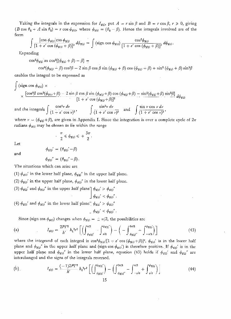
Taking the integrals in the expression for Ira) , put A = r sin fi and B = r cos fi, r /> 0, giving (B cos 02 + .d sin 02) = r cos era), where era) = (0~, -/3). Hence the integrals involved are of the form
I c°s Cm)[ cos era) dCm ) = (sign cos era)) [1 + e' cos (¢2(1) + fi)]2 [1 + e' cos (¢2(~) +/3)]2
Expanding
cos~¢~(~as cos~[(¢2(~) + #) - p] -
cos2(¢m) +/3) cos-~/3 - 2 sin/3 cos/3 sin (¢m) +/3) cos (¢2<1) +/3) + sin~ (¢m) +/3) sin~/3
enables the integral to be expressed as
f (sign cos ¢2(1)) x
× [cos~# cos~(¢~¢, +/3) - 2 sin/3 cos/3 sin (¢2¢1)+/3) cos (¢~(1)+/3) + sin~(¢2¢~)+/3) sin~/3] d¢~(,) [1 + ~' cos (¢~<,+5)]=
f cos~d~ f sin~d~ and f s in ,cos ,d , and the integrals (1 + e' cos v) ~' (1 + e' cos v) 2 (1 Y e ~ cos v) 2'
where v = (¢m)+fi), are given in Appendix I. Since the integration is over a complete cycle of 2~r radians era) may be chosen to lie within the range
~r 3rr - g < ¢~(i) -< + ~-.
Let ¢2(1)' = (02(1) ' --]~)
and ¢2d' = (%/'- P).
The situations which can arise are
(1) era)' in the lower half plane, era)" in the upper half plane.
(2) era( in the upper half plane, ¢2(17" in the lower half plane.
(3) era)' and era)" in the upper half plane 7 ¢2(~' > era)"
• ] Cm)' < Cm)".
(4) era( and era)" in the lower half plane~ ¢2(~9' > era)"
J Since (sign cos era)) changes when era) = + ~/2, the possibilities are
. . . . 2Pl'2h' I ( ( ~ t 2 ~¢2(1)"] / (37r[2 -}- ~02(1)']1 (43) (a) h(1) k~ ~r~ , L \ d¢2(1 )' d~rl2 / k ,d ¢2(1)" d--rr/2 / J
where the integrand of each integral is cos2¢2(1)/[1 + e' cos (¢2(1) + /9)] ~, ¢2(1)' is in the lower half plane and era)" in the upper half plane and (sign cos era)') is therefore positive. I f era)' is in the upper half plane and era)" in the lower half plane, equation (43) holds if era)' and Cm/' are interchanged and the signs of the integrals reversed.
if 6m)' and era)" are in the upper half plane and 6 m ) ' < ¢2(1)", sign cos ¢~q)' being negative. If era)' > era)" equation (44) holds if era)' and era)" are interchanged and the signs of the integrals
reversed.
2pF2 V (C,~2(I)")(f,,2 f 3zr,2 ~,>2(1)' )i (C) I2(1)- h' k12r2 - - -}- (45) L\d¢2(1 )' / \0 ¢2(1)" ,d rr]2 d --;,rig /J
if era)' and ¢2(1)" are in the lower half plane and ¢~(1)' < ¢2(1)", sign cos era)' being positive. If qSm)' < ¢~(])" equation (45) holds if era)' and era)" are interchanged and the signs of the integrals
reversed. Let
f cos242(1)d¢2(1 ' Fl(¢m)) = [1 + e' cos (¢2(1) + /3)] 2'
so that the solutions may be expressed in the form
rr F <~ "' (46) (a) 12(1) = W l F1 2 q- 2 - F 1 ( ¢ 2 ( 1 ) ' ) - 1~V2(1) ,
(b) /2(1) = ~V1 [FI(¢2(1)") - FI(¢2(1)') + FI(~) -- F I ( ~ ) + El ( - - ~ ) 1 2 (47)
(c) (48)
= 4Pl'2kl~r~/h '. When era)' or era)" = + Tr/2 the solution may be obtained by the same where W 1 process as in Section 4.1.
The expression for I2(~) is of a simpler form since C is a constant in the integration,
i.e. 2pF2 ~22C E (sign V ( 02(1)" - f02(1)'=k'zr I (49) 12(2)
- h' C)L oom)' J02(1)" •
where the integrand of each integral is (1 + e' cos 02) -2.
Let
f dO 2 F2(02) = (1 + e' cos 02) ~' giving the solution
12(2) = W2(sig n C) VF~(O,m ") -F'(Oz(v') + F2(0m)' + 27r)~ (so) 2 L d
where
Hence,
4Pl'2 W 2 - h' k22C2"
t'" [G(oDI dO2 = (51) 02=0
where I2(1) is given by the appropriate expression (equations (46), (47) or (48)} and I2(2) is determine.d
by equation (50).
16
In the case of the integral of the torque about the Ys axis we wish to evaluate the quant i ty
2Pl'2 &'=--U-×
rr0 ( ;'h321A cos 0 2 - sin 021(A cos B sin x / / (1 +. e' cos 02) ~ L,J 02(2)'
- k421A sin 02+ B cos Oz[(A sin 02 + B cos 02) dOs (1 + e' cos 02) 2
Let
_ ~ o 2 ( 2 ) ' + 2 ~ ka2[A
d02(~)'"
cos 02 - B sin 02[(A cos 0 2 - B sin 02) -
(1 + e' cos 02) 2
- k42]A sin 02 + B cos 021(A sin 0.2 + B cos 02) dO2] . (1 + e' cos 02) 2
2p1,2 i(o2(2)" k 21A cos 0 2 - B sin O2[(A cos 0 ~ - B sin 0~) d O 2 _
I2(a) -- h' Ld 02(2 ), (1 + e' cos 0~) 2
and
I2(~ - -
(52)
where
f cos2¢2(3 ) Let Fa(¢2(a)) = [1 + e' cos (¢2(a)-e)] 2
./2(3) = W 3
d¢2(3 ) so that equation (55) may be writ ten
4P1'2 W 3 - h' ha2r2"
- G(¢~(d) - G(¢2(d') (56)
The expression for 12(4) is identical with that for "/m) if k42 is substi tuted for hi 2 and 02(1)' and 0m)" replaced by 0~(2)' and 03(2)" respectively. However, since 03(2)' and 02(2)" are always rr radians apart the only case to be considered is that corresponding to equation (43),
i.e. 2Pl '') h42r2 I ( ( . l ~- f¢o.(4)") { ~3.t2 ~¢m),) l ./2(4)
if ¢2(4/ is in the lower half plane. If ¢2(4)" is in the lower half plane equation (57) applies if ¢2(4( and ¢2(4/' are interchanged and the signs of the integrals reversed. Here, ¢3(4)' = (02(~)'-fi) and ¢ ~ ( j = (02c2; ' - ~).
f cos2 ¢ 4Pl'2 [ l + e ' c o s ( ¢ + f i ) ] 2 d ¢ and W a - h' h4Zr2"
I3(4) =
where
G ( ¢ ) =
Hence,
J2'--- o2=0 IF2(02)1 ~ dO2 = 113(3)-"/2(~1 (59)
where "/2(3) and "/2(4) are given by equations (56) and (58). When ¢2(3)", ¢2(3)' or ee(a)", ¢2(4)' = + 7r/2 the solution may be obtained by the process used in Section 4.1.
Finally, in order to develop an expression for equation (38) we must evaluate the quanti ty
&' = 2p1(2 [[o~(3;'a¢lClC- kdlA cos G _ B s i n GI(A c o s G - B sin G) dO.- E - L-., o2(a)" (1 + e' cos G) 2 ,
! C°~(a) '+2~ hs~ I C[ C - h6zlA cos 02 - B sin 021(A cos 0~ - B sin 0z) d02~ (60) ~o~(a)'" (1 + e' cos 02) 2 J
Let 2Pl'2 F 02(3)" I C[ C °2(a)'+2" I CI C
I2(5) - h' Lh~2 f (1 + e' dO2- h52 ~ (1 + e' dO 2J (61) 002(3; cos 03)2 J02(3)" cos 0~) 2
"/2(6) ~ - - - - 2P1'2 I ~o2(3)'" [A cos 02 - B sin 02I(A cos 02 - B sin 03)
h' h6~ dO2 - J02(a)' (1 + e' cos 03) 2
_k62f°2(a)'+"~lAcos02 - BsinO21(Acos02- B sin 02) ] J o2(3)" (1 + e' cos 02) 3 dO2 " (62)
and
18
The expression for I~(5) is identical with that for I2(2) if k52 is substituted for k2 2 and 0m/ and 0m(' replaced by 02(8( and 0~(3(' respectively,
i.e.
2PZ'Zkso"CZ<sign C)F( %(3;'- f °2(a>'+z~] ' (63) 12(5) - - h ' LJ 02(3) ' J02(3)" _l
where the integrand of each integral is (1 + e' cos 02) -2,
0 ,' and The expression for 12(6) is identical with that for 12(31 if ks z is substituted for k32 and 2(2, 02121" replaced by 02(81' and 0~(~)" respectively. However, the solution must be expressed as one of three alternatives as in the case of 12(1).
(a) If ¢2(6/is in the lower half plane and ¢2(G)" in the upper half plane then
h , 0 , = W 6 Fak2]+ - Fa(¢2(6/)- F(¢2(j' ) . (65)
If ¢2(6)' is in the upper half plane and ¢216)" in the lower half plane equation (65) applies with ¢2(6/and ¢2{6!" interchanged and the sign reversed.
(b) If both ¢2(G)' and ¢2¢6)" are in the upper half plane then
if ¢2(6/< ¢2(61", and if ¢2¢61' > ¢2(6)" the equation applies with ¢2(6)' and ¢2(6)" interchanged and the sign reversed.
(c) If both ¢2(6)' and ¢2(6)" are in the lower half plane then
when ¢~(6)' < ¢2(0", and if ¢2(6( > ¢~{6)" the equation applies with ¢2(0' and ¢2(6/' interchanged and the sign reversed.
In these equations 4P1'2 . f c°s2¢d¢
W6- h' kG2r2 and F3(¢) = j [l + e' cos ( ¢ - e)] 2" ,
Hence
F (£) s; = Ir (o )l d02 = Ih(5)- I2(6)1 (68) 02=0
where I2(5) is given by equation (64) and I2(s) by the appropriate equation (65) to (67). The total amount of angular impulse per satellite orbit can therefore be expressed as
= [r (o2)l ~ dO2 = t i m ) - I2(2)] + Ih(a,- I2(~1 + ]I2(5~- h(6)l • (69) r = l 02=0
\
19 (87419) • B*
The quantities contained in the modulus signs of equation (69) are straightforward to evaluate for a given case and the author feels that the result is best expressed by this equation, rather than attempt to combine the individual constituents into one expression.
The total amount of angular impulse arT' is a function of the angle 0 and will be a maximum
for some angular position 0 = 0 M of the satellite in the plane of the ecliptic. I f J~l' is the maximum
value of J~,' as determined from equation (69), then if the satellite completes N orbits during one year, an upper estimate for the magnitude of angular impulse per year is simply
J.,v' = NJ,-r/. (70)
Alternatively one may take the mean value of JT', denoted by JT', for a change in 0 of 27r and use the expression
JN" = N[lr' (71)
as the total amount of angular impulse over a period of a year, as obtained by taking the mean value of the total angular impulse per satellite orbit.
An example will serve to illustrate the procedure in a particular case.
Suppose l 1 = m.a = n a = 1, (all other direction cosines being zero) so that X, Y, Z and X', Y', Z ' are coincident sets of axes. The satellite now orbits in a plane normal to the plane of the ecliptic,
the normal to the orbital plane being parallel with the direction of the minor axis of the earth's
orbit. Let z~ = z 2 = z, (all other torque arms being zero) so that the centre of mass of the satellite
is along the Z S axis at a distance z from the geometrical centre of the configuration. The surface
areas involved in the problem are S x s z s and S r s z ~ ; assume these to be equal areas--denoted by S. We have
A = cos0 , B = 0, C = s in0
k2 ~ = ka 2 = z S .
The formula given in the general theory, for determining the points at which F1(02) = 0 cannot be satisfied for any choice of 0.a, i.e. the torque is unidirectional about the X s axis.
If we assume that the satellite orbit is circular then F2(O.a ) = O.a and l~(.a) reduces to give
4(.a) = W.a(sign sin O) ( - 7r) therefore
4Pl'~ • 11' = [ - I,a(~)] = T zS~ sin=O , ,
i.e. . : ' Z
J,' = 2 P T ' z S sin~0
since all the components of the expression are positive quantities, and T ¢ = 2rrl'2/h ' is the Orbital period of the satellite about the earth. ~
20
The conditions for P2(02)= 0 give 0~(~)' = 7r/2, 02(2)" = 37r/2. We have ~b2¢ ) = ~r/2 and ~2(~)" = 37r/2, and this is therefore the special case when the integration limits are coincident with the limiting points. Consequently we may write
since sign cos q~z is negative over the range rr/2 to 37r/2 and positive over the range -7r/2 to ~r/2,
i.e. 2Pl'~
I2(8) = h ' k32r~r
= - P T ' z S cos20.
Now -/2(4) = 0 since k4 2 = 0, therefore
J2' = P T ' z S cos20. (73)
Since there is no torque about the Z.~ axis we have Ja' = 0. Hence
JT' = P T ' z S ( 2 sin20 + cos20). (74)
The total amount of angular impulse arT' is a maximum when 0 = 7r/2 or 37r/2 and thus
and
where T E = N T ' is the period The mean value of Jz ' is
JM' = 2 P T ' z S (75)
JN' = 2 P z S T ~ (76)
of the earth in its orbit round the sun.
i.e.
- P T ' z S (2,~ (2 sinZ0 + cosZO)dO, J T ' - - 2~ d0=0
- 3 JT' = ~ P T ' z S . (77)
6. At t i tude Deviations of an Earth-Pointing Gravity-Gradient-Stabilised Satellite due to Radiation
P~'essure.
Consider the case where the satellite is moving along an orbit whose plane is perpendicular to
the plane of the ecliptic and where the Ys rotational axis is pointing towards the sun. Let the
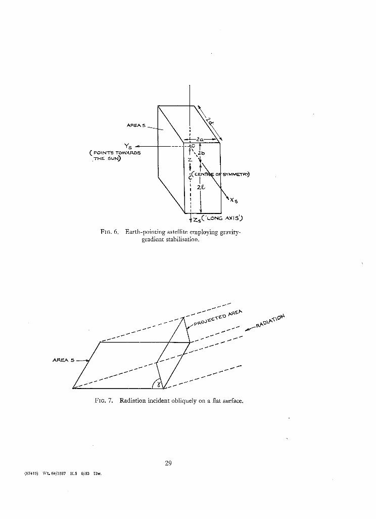
centre of mass lie along the 'long-axis' (i.e. the axis of minimum moment of inertia) of the vehicle, the 'long-axis' being assumed to pass through the centre of symmetry as indicated by Fig. 6. In the
case of a gravity-gradient-stabilised satellite the 'long-axis' is the earth pointing axis. Let z be the
distance between the centre of symmetry and the centre of mass. The force on the satellite due to
radiation pressure is 2 P S (assuming complete reflection) where S is the surface area presented
to the sun. Also the torque about the centre of mass is 2PSz, acting along the X S axis, and is constant for all positions of the satellite in its orbit.
21
Ref. 1 shows that the attitude motion about the X s axis for an earth-pointing satellite (in a
circular orbit) relying solely on the gravitational restoring torque for its stabilisation, is described
by the equation
IxsO ~ ~- 4(Iz~ S - Izs)OJo201 + (I2(~ + I z s - I~-s)O 8 = L x s ' , (for small angles)
where Ixs , I~ s and I z s are the principal moments of inertia about the X~, Y z and Z s axes, 01
and 0 a are the angular deviations about the X s and Z s axes and co 0 is the angular velocity of the
satellite in its orbit; L x s ' is the component of any external disturbing torque about X s. In the
present instance L x s ' = 2PSz, and since this is a constant only the steady-state solution is of
interest, resulting in an attitude deviation given by
2PSz 0t = 4 ( I ~ - - I z s ) % ~"
Referring to Fig. 6 if a = d and the dimensions of the configuration are such that 21 = 8 ft,
2b = 2 ft and 2a = 3 ft, t h e n z = 3 ft, S = (21+2b)2a = 30 sq. ft., and if the mass of the satellite
is taken to be 500 lb then ( I y , s - I z s ) ~5 3 0 0 lb. ft ~. Taking co 0 as 10 -a rad. see-l, the attitude
deviation is of the order of 1½ degrees.
7. A Comparison of the Torques due to Radiation Pressure and the Earth's Gravitational FieM for a Space-Stabilised Satellite of Given Orientation.
Suppose l 1 = m 2 = n 3 = 1, (see Section 4.2). As in Section 6 let the centre of mass be a distance
z from the centre of symmetry so that the radiation-pressure torque given by equation (15) reduces to
r = 2PSz[ - ] s in 0[sin 0 i S + ]cos 0lcos 0 js] if
S x s z s = S~zz S = S . Therefore
I lr = 2PSz~/(sin40 + cos40)
and attains a maximum value given by
lrl n x = 2PSi .
From Section 3.2 of Ref. 1 it is shown that with the X s and Z s axes in the plane of the satellite's
orbit (making the orbital plane at right angles to the plane of the ecliptic in the present case) the
maximum value of the gravitational torque is given by
3 [rolm~x = ~ c°0~[Iz s - I x s t .
Hence, for this particular satellite having the orientation stated above, Irlm x = ]rOlm x when
COoe = 4PSz/3[Iz s - / x a [ . For a circular orbit Wo e = GMjz/R a where M E is the mass of the earth,
G the gravitational constant and R the distance between the satellite and the centre of the earth,
i.e.
4PSz
giving R ~ 10,000 miles if we chose S = 30 sq. ft, z = 3 ft and IIzs - I x s [ = 5300 lb. ft 2 as in
Section 6.
22
8. Concluding Remarks.
The equations developed in the text may be used to estimate the annual amount of angular impulse required from a satellite attitude-control system to couriter the solar radiation-pressure torque. Two situations are considered, the space-stabilised satellite and an earth-stabilised satellite in a non-precessing orbit. The analysis assumes a specific geometrical configuration, namely that of a rectangular prism, and also complete reflection at all surfaces. The necessary amount of angular impulse may be provided by any suitable control system, for example by reaction jets or accelerating flywheels.
The expressions for the space-stabilised satellite indicate that as the satellite completes one orbit round the sun the nett angular impulse about any one of the satellite axes is zero (the effect of the eccentricity of the earth's orbit being neglected). If this were strictly true, the radiation-pressure torque could be most effectively compensated by the use of accelerating flywheels, one such wheel along each of the satellite axes. The angular momentum attained by a given flywheel during one half of the orbit would be nullified during the second half of the orbit, resulting in no nett increase or decrease of the flywheel's angular velocity. In general, however, the situation is not so simple as this since the satellite spends a certain proportion of its time passing through the earth's shadow. Owing to orbital regression and the fact that the 'satellite's orbit about the earth may be an ellipse, the unidirectional change of angular momentum about a given axis during one half of the earth's orbit Will not in general be compensated exactly during the remainder of the orbit. Thus, an accelerating flywheel would gain or loose angular momentum during the course of one year. Such a nett change of flywheel angular momentum may be very small in comparison to the build up of angular momentum between successive positions at which the torque component concerned is zero, and therefore be of little significance. However, if it were desired to use small flywheels for control over a period of several years the shadowing effect of the earth should be 'considered, especially if relatively large torque arms were present. This may very well be the case when the principal axes of inertia of the satellite have been made as nearly equal as possible in order to minimise the torque arising from the earth's gravitational-field gradient, especially if air-drag torques are small and meteoroid hazards not serious.
The relative importance of the perturbation torques due to radiation pressure and the earth's gravitational-field gradient may be inspected by comparing the angular impulse given by equation
(16) of Section 4.1 with the corresponding quantity determined by considering the angular impulse produced by the gravity-gradient torque over a period of a year.
The equation for the radiation-pressure torque about the centre of mass of the rectangular prism configuration indicates, as one might expect, that the torque is always zero if the centre of mass coincides with the centre of symmetry of the external shell. This may also be the case when all the surfaces are completely absorbing, and if so, the situation arising when the different surfaces have varying absorption characteristics will result in a nett torque acting on the vehicle even when the centre of mass coincides with the centre of symmetry.
23 (87419) B**
£
e ~
eE
h'
hE
( IY s, Iz ) J .
J2~ t
J~v"
k,r 2
l'
L~
n
nX S, nYS~ nZ S)
N
P
LiST OF MAiN SYMBOLS
Velocity of light in vacuo
Eccentricity of satellite orbit round the earth
Eccentricity of earth's orbit round the sun
Angular momentum per unit mass of satellite in orbit round the earth
Angular momentum per unit mass of earth in its orbit round the sun
Principal moments of inertia of satellite
Total amount of angular impulse per year imparted to space-stabilised satellite to maintain perfect stabilisation against radiation-pressure
torques
Amount of angular impulse per year about individual axes of space-
stabilised satellite (r taking values 1, 2, 3)
Nett angular impulse imparted to space-stabilised satellite during one
year by radiation-pressure torques
Total amount of angular impulse per satellite orbit that has to be supplied about satellite axes for perfect stabilisation of" earth-
pointing satellite against radiation-pressure torques
Amount of angular impulse per satellite orbit about individual axes
of earth-pointing satellite (r taldng values 1, 2, 3)
Maximum value of Jr '
Upper estimate for amount of angular impulse per year for earth-
pointing satellite
Mean value of J~,'
Estimate for amount of angular impulse per year for earth-pointing
satellite based on the mean value of ,IT'
Positive constants (r taking values 1 to 6)
Semi-latus rectum of satellite orbit round the earth
Semi-latus rectum of the earth's orbit round the sun
Torque components about centre of mass of satellite due to radiation incident on faces 1, 2, 3 (or opposite faces) see Fig. 2 (r = 1, 2, 3)
Unit vector specifying direction of the sun's radiation relative to
satellite axes
Components of n along satellite axes (earth-pointing satellite)
Number of orbits round the earth made by the satellite during one year
Pressure of sun's radiation on a 'black-body' surface placed at right angles to the direction of the radiation at the mean distance of the
earth from the sun
t 24
r 1, lr 2, lr 3
S r
S x s z S, S Y ,gz 8, S x s y S
T'
T.
x , y,,, z,.
r
Axes
Pl, F2, Fa
0
02
X', Y', Z'
(i', j ' , k')
x , g , z
(i, j,k)
xz, Ys, z ,
6o, Js, ks) [(/1, mr, nl);
COS ~tX, COS ~ y , COS TZ
LIST OF MAIN SYMBOLS--continued
Position vectors of centres of pressure of faces 1, 2, 3 relative to centre
of mass of satellite--see Fig. 2
Solar constant
Areas of faces of rectangular prism
Period of satellite in its orbit round the earth
Period of earth's orbit
Components o f t r along satellite axes (r taking values 1, 2, 3)
Torque about centre of mass of satellite due to radiation pressure (complete reflection)
Components of r along satellite axes
Angle defining motion of the satellite in the plane of the ecliptic
Angle defining the angular motion of earth-pointing satellite in its orbit
System of space-fixed axes, origin at the centre of mass of the satellite
and having Z' normal to the plane of the ecliptic and X' and Y' along the major and minor axes respectively of the earth's orbit round the
s u n
Unit vectors along (X', Y', Z')
Set of space-fixed axes, origin at the centre of mass of the satellite
Unit vectors along (X, Y, Z)
Satellite axes (origin at the centre of mass)
Unit vectors along (Xe, Ys, Zs)
Direction cosines of X', Y', Z' axes relative to X Y Z
Direction cosines of n relative to axes X, 11, Z
No. Author
1 N . E . Ives ..
REFERENCE
Title, etc.
Principles of attitude control of artificial satellites. A.R.C.R. & M. 3276. November, 1959.
25
A P P E N D I X I
Integrals Occurring.in the Text
f du [ e s inv 2 ( ~ / ( 1 - e ) 2 ) ] (1 + e cos v) 2 - (1 - e ~) (1 + e cos v) + (1 - e2) 8m tan-1 ~ - e tan
f cos%dr I [ e s inv 2 ( 1 - 2 e 2) ( % / ( 1 - e ) tanV~7 (1 + e cos v) 2 - e ~ v - (1 - e 2) (1 + e cos v i + 0 Z e ~ tan-1 ~ 2 / J
f [ e s i n v 2 1 - - e 2) 1 sin~vdv 1 ( l + e c o s ~ / ( 1 - e 2) ( ~ / ( ~ ) (1 + e cos v) ~ - e 2 v) + tan-1 tan - v
f s i n v c o s v d v _ 1 [ e cosv l o g ~ ( l + e c o s v ) ] . ( f - + e c o s ; ~ e ~ (1 + e c o s v )
These integrals are taken between the limits specified in the appropriate sections of the text.
A P P E N D I X II
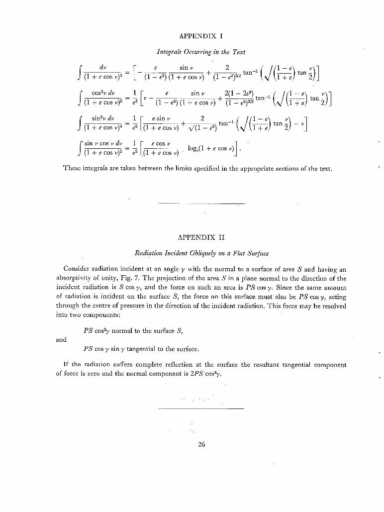
Radiation Incident Obliquely on a Flat Surface
Consider radiation incident at an angle 7 with the normal to a surface of area S and having an absorptivity of unity, Fig. 7. The projection of the area S in a plane normal to the direction of the incident radiation is S cos 7, and the force on such an area is PS cos 7. Since the same amount of radiation is incident on the surface S, the force on this surface must also be PS cos 7, acting through the centre of pressure in the direction of the incident radiation. This force may be resolved into two components:
and PS cos~7 normal to the surface S,
PS cos 7 sin 7 tangential to the surface.
If the radiation suffers complete reflection at the surface the resultant tangential component of force is zero and the normal component is 2PS cos~7.
, , . : -
26
o ~
y ,
FIG. 1.
/ f
Z-s
Orientation of satellite axes relative to the outer geometrical shell.
FAC E 3 /
• / ~ / t / I T3~-
J ii 0 , / J
ZS
~..X s
~ = U N I T VECTOR ,9PECII:'YING DIIRECTION OF RADIATION, ~ , r 2 ~ t 3 -- POSITION VECTORS OF CENTP.ES OF PRESSURE OF FACES 1~2.,3 RELATIVE TO THE CENTRE_ OF MA55.
FIG. 2. 'Cut-away' view of satellite.
27
9
FIG. 3.
÷
,~rJ
SU R, FAGF.. NORMAl
Radiation incident on face 1.
y '
FIe. 4. Motion in the plane of~the ecliptic.
~X,
Y=Y5
~ Z s ( POINTS TOWARD5 CENTRE Ol =" EARTH")
FIG. 5. Rotation of satellite axes for an earth-pointing satellite.
~ ~ ~ . / /~ . / ~ O j ~ . C ' ~ - ~ . - - x "" . . . - - - - - ..~-- f _ ~ m ~'~°~
AP, EA 5
FIG. 7. Radiation incident obliquely on a flat surface.
'(87419) W~ 64/1857 K.5 8/63 Hw.
29
Publications of the Aeronautical Research Council
A N N U A L T E C H N I C A L R E P O R T S O F T H E A E R O N A U T I C A L
R E S E A R C H C O U N C I L ( B O U N D V O L U M E S )
1942 Vol. I. Aero and Hydrodynamics, Aerofoils, Airscrews, Engines. 75s. (post 2s. 9d.) Vol. n . Noise, Parachutes, Stability and Control, Structures, Vibration, Wind Tunnels. 47 s. 6d. (post 2s. 3d.)
1943 Vol. I. Aerodynamics, Aerofoils, Airscrews. 8os. (post 2s. 6d.) Vol. n . Engines, Flutter, Materials, Parachutes, Performance, Stability and Control, Structures.
9os. (post 2s. 9d.) 1944 Vol. I. Aero and Hydrodynamics, Aerofoils, Aircraft, Airserews, Controls. 84s. (post 3s.)
¥o1. n . Flutter and Vibration, Materials, Miscellaneous, Navigation, Parachutes, Performance, Plates and Panels, Stability, Structures, Test Equipment, Wind Tunnels. 84 s. (post 3s.)
I945 Vol. I. Aero and Hydrodynamics, Aerofoils. I3OS. (post 3s. 6d.) Vol. II. Aircraft, AJrscrews, Controls. I3OS. (post 3s. 6d.) Vol. I n . Flutter and Vibration, Instruments, Miscellaneous, Parachutes, Plates and Panels, Propulsion.
I946 Vol. I. Accidents, Aerodynamics, Aerofoils and Hydrofoils. i68s. (post 3s. 9d.) Vol. II. Airscrews, Cabin Cooling, Chemical Hazards, Controls, Flames, Flutter, Helicopters, Instruments and
Special Volumes Vol. I. Aero and Hydrodynamics, Aerofoils, Controls, Flutter, Kites, Parachutes, Performance, Propulsion,
Stability. I26S. (post 3s.) Vol. II. Aero and Hydrodynamics, Aerofoils, Airserews, Controls, Flutter, Materials, Miscellaneous, Parachutes,
Propulsion, Stability, Structures. I47S. (post 3s.) Vol. III. Aero and Hydrodynamics, Aerofoils, Airscrews, Controls, Flutter, Kites, Miscellaneous, Parachutes,
Propulsion, Seaplanes, Stability, Structures, Test Equipment. I89S. (post 3s. 9d.)
Reviews of the Aeronautical Research Council 1939-48 3s. (post 6d.) 1949-54 5s. (post 5d.)
Index to all Reports and Memoranda published in the Annual Technical Reports I9O9-I947 R. & M. 2600 (out of print)
Indexes to the Reports and Memoranda of the Aeronautical Researcl~ Council Between Nos. 2351-2449 R. & M. No. 245 o 2s. (post 3d.) Between Nos. 2451-2549 Between Nos. 2551-2649 Between Nos. 2651-2749 Between Nos. 2751-2849 Between Nos. 2851-294-9 Between Nos. 295i-3o49 Between Nos. 3o 51-3149
R. & M. No. 2550 2s. 6d. (post 3d.) R. & M. No. 2650 2s. 6d. (post 3d.) R. & M. No. z75o 2s. 6d. (post 3d.) R. & M. No. 285 o 2s. 6d. (post 3d.) R. & M. No. 2950 3s. (post 3d.) R . & M . No. 3o5 ° 3 s.6d. (post 3d.) R. & M. No. 315o 3s. 6d. (post 3d.)
HER MAJESTY'S STATIONERY OFFICE .from the addresses overleaf
R. & M. No. 3332
Crown copyright x963
Printed and published by HER MAJESTY'S STATIONERY OFFICE
To be purchased from York House, I~ngsway, London w.c.z
423 Oxford Street, London w.I 13A Castle Street, Edinburgh 2
Io9 St. Mary Street, Cardiff 39 King Street, Manchester 2
5o Fairfax Street, Bristol I 35 Smallbrook, Ringway, Birmingham 5
8o Chichester Street, Belfast x or through any bookseller