1 THE EFFECTS OF SYSTEM GROUNDING, BUS INSULATION AND PROBABILITY ON ARC FLASH HAZARD REDUCTION – PART 2: TESTING Copyright Material IEEE Paper No. PCIC–2014-4 John P. Nelson, P.E. Joshua Billman, P.E. James Bowen, P.E. Dane Martindale, P.E. Life Fellow, IEEE Member, IEEE Fellow, IEEE Member, IEEE NEI Electric Power Eng NEI Electric Power Eng Aramco Services Company Aramco Services Company P.O. Box 1265 P.O. Box 1265 9009 West Loop South 9009 West Loop South Arvada, CO 80001 Arvada, CO 80001 Houston, TX 77096 Houston, TX 77096 USA USA USA USA [email protected][email protected][email protected][email protected]Abstract – This paper provides a follow-up to the paper, The Effects of System Grounding, Bus Insulation and Probability on Arc Flash Hazard Reduction – The Missing Links. [1] In that paper, system grounding and bus insulation were considered a means of reducing the probability of an arc flash incident by approximately two orders of magnitude. In September 2013, additional testing was conducted on a low voltage motor control center with the expectation that engineering enhancements such as insulated vertical bus, high resistance grounding, and other techniques, could be implemented to further reduce the probability of an arc flash incident. The testing performed was with faults initiated in locations typically found in operating petrochemical facilities, in low voltage motor control centers, with the starter unit door open. This paper discusses the findings of testing on real- world electrical equipment in an effort to further understand and minimize the probability of an arc flash incident. The paper reviews the physics of the arcing fault and how ignition wire, geometry, and the number of anode/cathode pairs all contribute to arcing fault energy and personnel exposure. Index Terms - low voltage motor control center, arc voltage, safety by design, arcing faults, impedance grounding, high resistance grounding, arc physics, solidly grounded. I. INTRODUCTION Arc initiation in the functioning Low Voltage Motor Control (LVMCC) is typically initiated in one of two ways. These typical initiators are through a catastrophic failure of the insulation system or the introduction of a foreign object across the air gap between conductors. The insulation failure may be caused by: 1) a loose connection causing overheating that over time can ionize enough air and insulation to result in a flashover, 2) misalignment forced to the point that insulation fractures or 3) the unsuccessful interruption of a short circuit resulting in an un-cleared fault. Faults initiated by a foreign object inserted across the air gap, may be caused by: 1) slippage of a tool such as an uninsulated screw driver or a metal fish tape, or 2) rodents or reptiles trying to find a warm place to nest, either directly bridging the air gap between conductors, or building a nest that bridges the insulation system. [2] The first paper in this series examined how high resistance grounding (HRG) and enhanced engineering techniques, such as insulated buses, could reduce the probability of an arc blast incident by approximately two orders of magnitude. This in turn, has the potential to drastically lower the probability of an arc flash injury or fatality. [3] Early manufacturer’s development testing involved standard 600 V switchgear. In September 2013, initial testing was performed on a LVMCC, anticipating results similar to testing which previously occurred on 600 V switchgear. The tests also included several barriers to isolate the high arc energy area, where technicians are exposed. A total of 15 tests were planned, using a combination of 15 new, 480 V, size 1, and size 3, motor starters units. After each test, the test specimen of three vertical sections was cleaned and arranged for each subsequent test. Results indicated the test specimen was sufficiently damaged so only 12 of the 15 tests could be conducted. The series of tests conducted included both solidly grounded and high resistance grounded test sources. Since most of the arc flash testing research in the industry has been performed with an arcing three-phase fault, this battery of tests were initiated using a series of phase-to-ground and phase-to-phase faults. 1) Tests with a High Resistance Grounded System (HRG) A series of tests was conducted on a HRG system. Phase- to-ground tests were conducted to show the benefit of the HRG, by limiting fault current to a value with no arc flash issues. Phase-to-phase faults were then conducted to understand the impact of initiating a fault which is closer to real-world experience than the three-phase arcing fault. Faults were initiated, both downstream and upstream, from the 480 V LVMCC motor starter unit’s molded case circuit breaker. 2) Tests with a Solidly Grounded System A series of tests was conducted on a solidly grounded system. Phase-to-ground and phase-to-phase tests were initiated both upstream and downstream on the LVMCC motor starter unit’s molded case circuit breaker. The remainder of this paper will discuss results and findings from the testing that was performed. A number of observations were made which were quite unexpected. The tests were conducted, not in the interest of repeatability, but for the purpose of investigating practical, real-world incidents.
Transcript
1
THE EFFECTS OF SYSTEM GROUNDING, BUS INSULATION AND PROBABILITY ON ARC FLASH HAZARD REDUCTION – PART 2: TESTING
Copyright Material IEEE
Paper No. PCIC–2014-4
John P. Nelson, P.E. Joshua Billman, P.E. James Bowen, P.E. Dane Martindale, P.E. Life Fellow, IEEE Member, IEEE Fellow, IEEE Member, IEEE NEI Electric Power Eng NEI Electric Power Eng Aramco Services Company Aramco Services Company P.O. Box 1265 P.O. Box 1265 9009 West Loop South 9009 West Loop South Arvada, CO 80001 Arvada, CO 80001 Houston, TX 77096 Houston, TX 77096 USA USA USA USA [email protected][email protected][email protected][email protected]
Abstract – This paper provides a follow-up to the paper, The Effects of System Grounding, Bus Insulation and Probability on Arc Flash Hazard Reduction – The Missing Links. [1] In that paper, system grounding and bus insulation were considered a means of reducing the probability of an arc flash incident by approximately two orders of magnitude. In September 2013, additional testing was conducted on a low voltage motor control center with the expectation that engineering enhancements such as insulated vertical bus, high resistance grounding, and other techniques, could be implemented to further reduce the probability of an arc flash incident. The testing performed was with faults initiated in locations typically found in operating petrochemical facilities, in low voltage motor control centers, with the starter unit door open. This paper discusses the findings of testing on real-world electrical equipment in an effort to further understand and minimize the probability of an arc flash incident. The paper reviews the physics of the arcing fault and how ignition wire, geometry, and the number of anode/cathode pairs all contribute to arcing fault energy and personnel exposure. Index Terms - low voltage motor control center, arc voltage, safety by design, arcing faults, impedance grounding, high resistance grounding, arc physics, solidly grounded.
I. INTRODUCTION
Arc initiation in the functioning Low Voltage Motor Control (LVMCC) is typically initiated in one of two ways. These typical initiators are through a catastrophic failure of the insulation system or the introduction of a foreign object across the air gap between conductors. The insulation failure may be caused by: 1) a loose connection causing overheating that over time can ionize enough air and insulation to result in a flashover, 2) misalignment forced to the point that insulation fractures or 3) the unsuccessful interruption of a short circuit resulting in an un-cleared fault. Faults initiated by a foreign object inserted across the air gap, may be caused by: 1) slippage of a tool such as an uninsulated screw driver or a metal fish tape, or 2) rodents or reptiles trying to find a warm place to nest, either directly bridging the air gap between conductors, or building a nest that bridges the insulation system. [2] The first paper in this series examined how high resistance grounding (HRG) and enhanced engineering techniques, such as insulated buses, could reduce the probability of an
arc blast incident by approximately two orders of magnitude. This in turn, has the potential to drastically lower the probability of an arc flash injury or fatality. [3] Early manufacturer’s development testing involved standard 600 V switchgear. In September 2013, initial testing was performed on a LVMCC, anticipating results similar to testing which previously occurred on 600 V switchgear. The tests also included several barriers to isolate the high arc energy area, where technicians are exposed. A total of 15 tests were planned, using a combination of 15 new, 480 V, size 1, and size 3, motor starters units. After each test, the test specimen of three vertical sections was cleaned and arranged for each subsequent test. Results indicated the test specimen was sufficiently damaged so only 12 of the 15 tests could be conducted. The series of tests conducted included both solidly grounded and high resistance grounded test sources. Since most of the arc flash testing research in the industry has been performed with an arcing three-phase fault, this battery of tests were initiated using a series of phase-to-ground and phase-to-phase faults.
1) Tests with a High Resistance Grounded System (HRG)
A series of tests was conducted on a HRG system. Phase-to-ground tests were conducted to show the benefit of the HRG, by limiting fault current to a value with no arc flash issues. Phase-to-phase faults were then conducted to understand the impact of initiating a fault which is closer to real-world experience than the three-phase arcing fault. Faults were initiated, both downstream and upstream, from the 480 V LVMCC motor starter unit’s molded case circuit breaker. 2) Tests with a Solidly Grounded System
A series of tests was conducted on a solidly grounded system. Phase-to-ground and phase-to-phase tests were initiated both upstream and downstream on the LVMCC motor starter unit’s molded case circuit breaker. The remainder of this paper will discuss results and findings from the testing that was performed. A number of observations were made which were quite unexpected. The tests were conducted, not in the interest of repeatability, but for the purpose of investigating practical, real-world incidents.
With his 1982 paper, Ralph Lee [3] pioneered investigating the electrical arc blast hazard. Since that time, considerable testing has been conducted, papers written, standards and codes issued, and arc flash hazard studies performed, all in an effort to improve electrical safety in the workplace. There is little doubt that the industry presently has an appreciation for the concern by Ralph Lee on the dangers of the electrical arc blast. However, at the present time, there are still a number of unanswered questions as to how best to protect the worker from such hazards, whether through personal protective equipment (PPE) or safety by design with the PPE as a level of back-up protection. With regard to the proper PPE, there are large variations in the estimated value of incident energy levels based on the different models available within the industry. As discussed in [1], the number of variables is so great that an exact value of incident energy level cannot be reasonably determined. The incident energy level from one installation to another with relatively similar designs can and will vary considerably due to these variables. Therefore, it is important to grasp the basic concept of incident energy, which Ralph Lee describes in a succinct manner.
For a simple single-phase circuit, Fig 1a, the power delivered to an arc is determined by Equation (1).
Pa = Vs*If**cos (θ) (1)
Where, Pa = fault power dissipated (Watts) Vs = system voltage (Volts) If = fault current (Amps) Cos(θ) = Power factor The maximum power transfer, Pmax, occurs when arc
resistance, Ra, equals system impedance, ZS, so that cos(θ) = 0.5 and Equation (1) is simplified to:
Pmax = 0.5*Vs*If (2)
Where, Pmax = max power dissipated across the
arc (Watts) And for a three phase circuit:
Pmax = 0.5 √3VsIf (3)
1a) Single Phase Equivalent Circuit
1b) Three Phase Equivalent Circuit
Fig. 1 Equivalent Arcing Fault Circuit
The energy associated with the fault is linearly proportional to the maximum power and time. Therefore, the maximum energy associated with a fault is simply:
Emax = Pmax * Time
(4)
Where, Emax = maximum energy (Joules)
Assuming a point source of energy, which holds equally
true with an arc-sphere of energy, the incident energy at a known distance from the point source correlates to a spherical area relationship of:
Ein = Emax Joules/cm2 (5)
4*π*D2 Where,
Ein = maximum incident energy level at a distance D in centimeters
Using 5 Joules = 1.2 Calories to convert (5) to Cal/cm2 for a three phase fault, Ein = (0.24) (1/2 * √3 * Vs * If) (Time) Cal/cm2 (6) 4πD2
= 0.0165 * Vs * If * (Time) Cal/cm2 (7)
D2
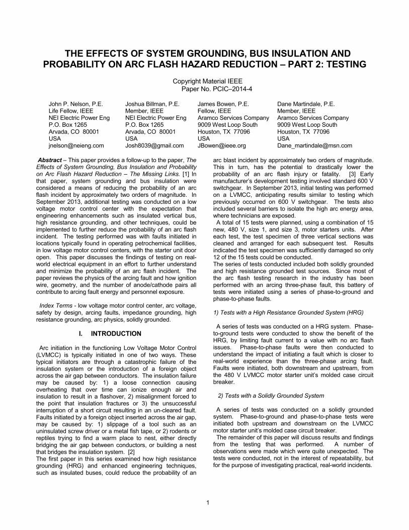
Now, (7) refers to a point source of energy and that energy emanates spherically from that source. For a number of years, Lee’s equations were used to calculate incident energy levels. However, one notable flaw in his equations is the fact that they are only valid in open air, as experienced with a fault on a power line in an open-air substation. The incident energy from a fault originating inside the equipment was observed to be different from a fault originating in open air. As such, considerable research has been conducted on an “arc in a box.” In review of the relative maximum energy levels that may be present in any given fault, several aspects must be considered. First, consider a 480 V system with fault current levels ranging from 5 to 100 kA. Second, consider the energy for times of 0.1, 0.5, and 1.0 seconds. The calculated results using (7) and converting it to Joules are shown in Table 1.
100 4.15 20.76 41.52 An interesting point that Lee made was that his
calculations were based on maximum power transfer, which naturally assumes that the arc resistance is equal to the system impedance. For any other value of arc resistance, maximum power and likewise, maximum energy is not transferred to the arc blast. Therefore, the use of Lee’s equations should provide worst-case energy levels at the point source. From there, the magnitude and direction of the incident energy is dependent on the enclosure geometries and the direction of the electrodes (buses/conductors).
III. ARC PHYSICS REVIEW
During the tests, the flat three phase bus orientation did not only maintain an arcing current from C phase to B phase and from B phase to A phase. Rather, the test sample clearly showed signs of multiple arcs with current using the structural steel to create a current path from C phase to A phase. This test battery demonstrated at least four separate anode/cathode combinations occurring during a full loop of three phase current. To understand the energy release that occurs and how this is disadvantageous when considering the impact of the various current flows, the physics of the arc must be reviewed. The high energy, low voltage electric arc in atmospheric conditions has been studied in the development of low voltage air circuit breaker designs Electric arcs generated in the circuit breaker operation closely match the method in which arc faults are created with the human interface in low voltage motor control centers. Such is also the case when drawing a screwdriver from an energized pair of terminals. During an arc fault, when the contacts begin to separate, the current density becomes very high at the few microscopic peaks in the physical surface imperfections. The last points to break connection have all of the current of the fault traveling through those few peaks in the contact, resulting in heating that is sufficient for melting, and in some cases, vaporization. The localized vaporization leads to a fast discharge between the parting contacts in the surrounding area. This vaporization occurs at the copper boiling temperature of 2835 K, much higher than the copper melt temperature of 1357 K.
As the contacts continue to stretch the gap, the arc develops into an arc with roots at the anode and cathode. Depending on the polarity of the sinusoids of the phase, or phases of the fault current, the anode and cathode shift with each zero passing of the sinusoid.
In a metal conductor, the voltage is proportional to the current flow through the conductor [9]. When the relationship of the current and voltage is observed across an arc of varying length, the current increases in magnitude as the arc voltage drop decreases in an inverse relationship. The plasma field created by the arc provides some level of thermal inertia, and as the sinusoid forces the current to approach a zero crossing, the driving voltage must be high enough to result in a restrike in order for the arc to be sustained. In the low voltage system, the local x/r results in a voltage crossing at the point of current zero. This lends to a rather unstable arc on the other side of the current zero, when the anode and cathode must reverse positions. This instability is in a race very similar to the transient recovery voltage experience in high voltage breakers post current interruption.
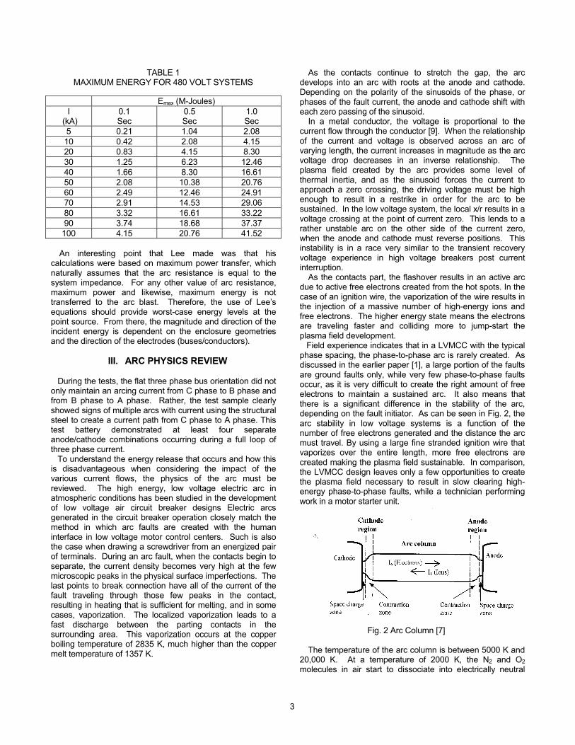
As the contacts part, the flashover results in an active arc due to active free electrons created from the hot spots. In the case of an ignition wire, the vaporization of the wire results in the injection of a massive number of high-energy ions and free electrons. The higher energy state means the electrons are traveling faster and colliding more to jump-start the plasma field development. Field experience indicates that in a LVMCC with the typical phase spacing, the phase-to-phase arc is rarely created. As discussed in the earlier paper [1], a large portion of the faults are ground faults only, while very few phase-to-phase faults occur, as it is very difficult to create the right amount of free electrons to maintain a sustained arc. It also means that there is a significant difference in the stability of the arc, depending on the fault initiator. As can be seen in Fig. 2, the arc stability in low voltage systems is a function of the number of free electrons generated and the distance the arc must travel. By using a large fine stranded ignition wire that vaporizes over the entire length, more free electrons are created making the plasma field sustainable. In comparison, the LVMCC design leaves only a few opportunities to create the plasma field necessary to result in slow clearing high-energy phase-to-phase faults, while a technician performing work in a motor starter unit.
Fig. 2 Arc Column [7] The temperature of the arc column is between 5000 K and
20,000 K. At a temperature of 2000 K, the N2 and O2 molecules in air start to dissociate into electrically neutral
4
atoms and free electrons. The higher temperature increases the speed of dissociation and the collisions result in a plasma as the temperature continues to increase towards 9000 K.
The electrical conductivity of the plasma field at this temperature is many orders of magnitude greater than air at atmospheric conditions. If the temperature is at the low end of the spectrum, the degree of ionization will be low and the gap will be non-conductive, as can be seen in Fig. 3. At the high end of the temperature spectrum the arc column will be a relatively good conductor with the conductivity approaching that of carbon. (Approximately 10 to 100 Siemens/cm)
This ionization phenomenon has been utilized in air blast circuit breakers to destabilize the arc. Using a large ignition source to simulate the fault in the field, greatly contributes to the initial arc temperature, the test is creating a much more severe case than would be experienced if the arc was started with a smaller ignition source. The ignition source should be representative of the causes of arcing faults experienced in field installation of LVMCC.
Fig. 3 Degrees of Thermal Ionization at Atmospheric Pressure [7]
The total arc voltage is a function of the current magnitude.
When the arc is in thermal balance, the arc reaches some minimum voltage drop. At this point, the arc is characterized by a maximum current and a minimum voltage.
The cathode region will emit current carrying electrons into the arc column. In addition, the area surrounding the cathode will be an accumulation of positive ions arriving from the arc column as the copper boils off.
The anode serves as a collector for the high-energy electrons arriving from the cathode. The electrons are moving at a high speed and will deliver a significant amount of energy to the anode. The anode surface will maintain a higher temperature due to the energy transfer. The surplus of electrons leads to the high electric field strength close to the anode surface. Just as in arc welding, where the electrode is positively charged to maximize the depth of penetration and weld speed and the energy released. The converse is true when the electrode is negatively charged the energy is greatly reduced.
At current zero, the anode and the cathode reverse polarity. As can be seen in the appendix A oscillography the system X/R will align voltage and current such that the voltage zero crossing is within msec of the current’s zero crossing, due to the addition of the purely resistive arc to the system. [8] If the plasma is hot enough, thermal inertia still causes re-ignition, reducing the required restrike voltage in the low voltage fault allowing current to continue to flow after the current zero.
Current continuation also occurs if the arc plasma is sufficiently ionized at the current zero, and the new cathode emits a sufficient amount of electrons. During this change, the arc channel will pass through a minimum in temperature and then start to heat again. This is where the arc is at its least sustainable point.
For a low voltage system if the arc plasma at the moment of current zero is weakly ionized, the arc will typically extinguish. This is different from medium voltage systems where the current lags the voltage, such that a peak voltage may exist allowing a continuation of the arc.
Arcs that occur from short circuits in power systems may conduct a current of many kilo-amps. The arc voltage in air at atmospheric conditions may vary, but is typically on the order of 10-50 V/cm for current on the order of 50 kA.
In the LVMCC with the typical phase spacing, the arc is rarely created. As discussed earlier, with a large portion of the faults being ground faults, only a few situations typically present themselves for multiphase arcing faults. Historically, faults at the bucket stabs begin with a hot stab deteriorating the solid dielectric insulation. This action then begins with a streamer that may eventually result in an electron avalanche and flash over. When a phase-to-phase fault does occur, the high level of available fault current can allow a significant plasma field to result in multiple arcs.
Due to the design of the LVMCC, arcs may exist between metal support pieces and conductors as shown in Fig. 6 and described in the observation portion of the paper. When these faults occur, the localized current vectors around any node must still sum to zero in compliance with Kirchhoff’s First Law. This does not prohibit the system from developing more than two arcs, and in some cases, as observed during this testing of multiple arcs in series. The multiple arcs in series utilize the steel supports, allowing multiple anodes of either copper or steel. The steel support has a different thermal ionization that was not studied as part of this paper.
IV. TEST SUMMARY
The test sample consisted of three vertical sections of
LVMCC with a 3200 amp horizontal bus and 600 amp vertical buses. The sample motor control center was populated with size 1 or size 3 starters for each test, with all other buckets removed. To simulate the case where the majority of injuries occur, the tests were all conducted with the bucket door open. The system configuration One Line Diagrams are shown in Appendix A1 for the high resistance grounded tests and A2 for the effectively grounded tests.
The three vertical sections were considered the smallest conceivable LVMCC with a 50kA available short circuit current that would be found in the typical industrial installation. The 3200 amp horizontal bus was selected due to experience with non-standard short time testing at 500
5
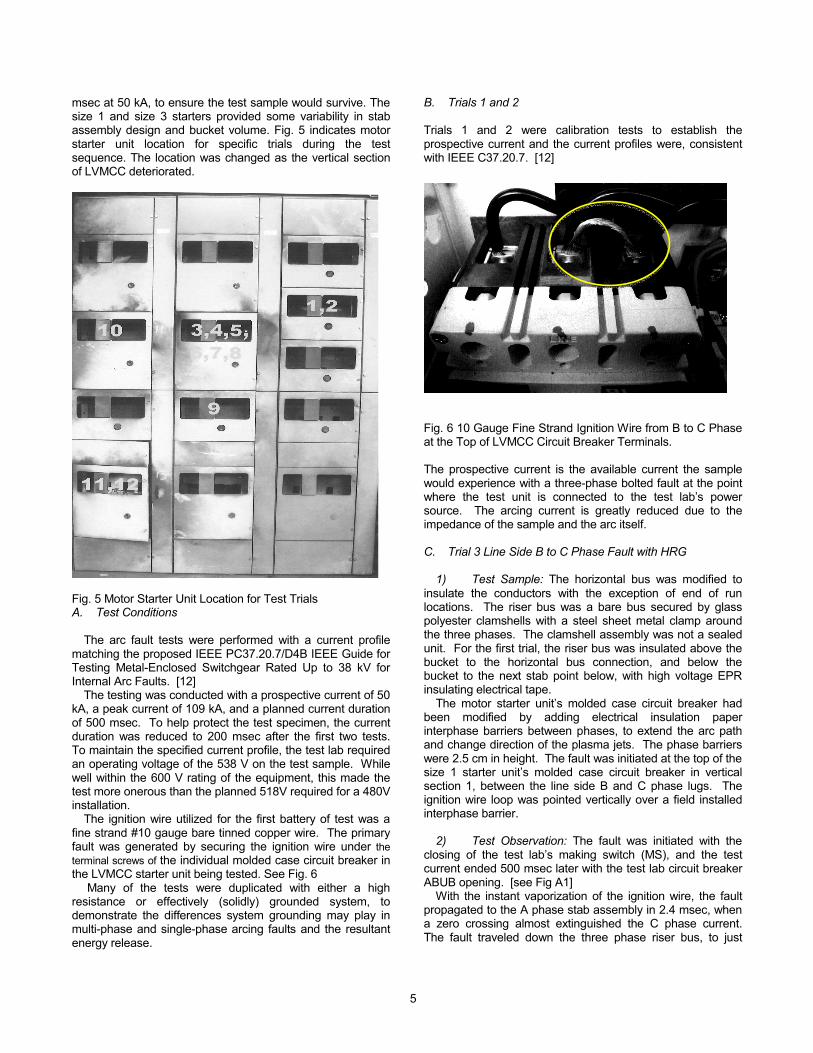
msec at 50 kA, to ensure the test sample would survive. The size 1 and size 3 starters provided some variability in stab assembly design and bucket volume. Fig. 5 indicates motor starter unit location for specific trials during the test sequence. The location was changed as the vertical section of LVMCC deteriorated.
Fig. 5 Motor Starter Unit Location for Test Trials A. Test Conditions
The arc fault tests were performed with a current profile matching the proposed IEEE PC37.20.7/D4B IEEE Guide for Testing Metal-Enclosed Switchgear Rated Up to 38 kV for Internal Arc Faults. [12]
The testing was conducted with a prospective current of 50 kA, a peak current of 109 kA, and a planned current duration of 500 msec. To help protect the test specimen, the current duration was reduced to 200 msec after the first two tests. To maintain the specified current profile, the test lab required an operating voltage of the 538 V on the test sample. While well within the 600 V rating of the equipment, this made the test more onerous than the planned 518V required for a 480V installation.
The ignition wire utilized for the first battery of test was a fine strand #10 gauge bare tinned copper wire. The primary fault was generated by securing the ignition wire under the terminal screws of the individual molded case circuit breaker in the LVMCC starter unit being tested. See Fig. 6
Many of the tests were duplicated with either a high resistance or effectively (solidly) grounded system, to demonstrate the differences system grounding may play in multi-phase and single-phase arcing faults and the resultant energy release.
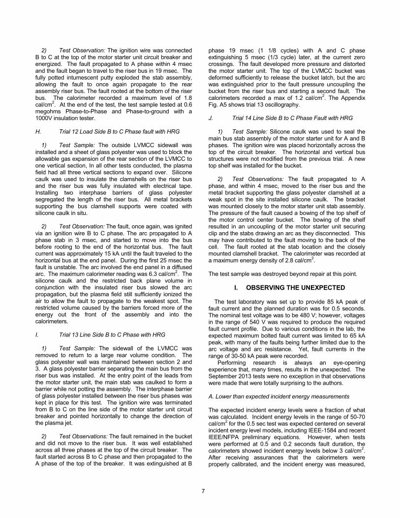
B. Trials 1 and 2 Trials 1 and 2 were calibration tests to establish the prospective current and the current profiles were, consistent with IEEE C37.20.7. [12]
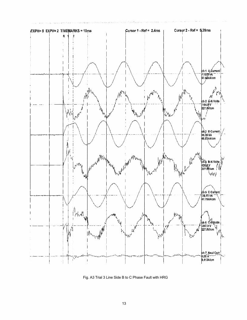
Fig. 6 10 Gauge Fine Strand Ignition Wire from B to C Phase at the Top of LVMCC Circuit Breaker Terminals. The prospective current is the available current the sample would experience with a three-phase bolted fault at the point where the test unit is connected to the test lab’s power source. The arcing current is greatly reduced due to the impedance of the sample and the arc itself. C. Trial 3 Line Side B to C Phase Fault with HRG
1) Test Sample: The horizontal bus was modified to insulate the conductors with the exception of end of run locations. The riser bus was a bare bus secured by glass polyester clamshells with a steel sheet metal clamp around the three phases. The clamshell assembly was not a sealed unit. For the first trial, the riser bus was insulated above the bucket to the horizontal bus connection, and below the bucket to the next stab point below, with high voltage EPR insulating electrical tape.
The motor starter unit’s molded case circuit breaker had been modified by adding electrical insulation paper interphase barriers between phases, to extend the arc path and change direction of the plasma jets. The phase barriers were 2.5 cm in height. The fault was initiated at the top of the size 1 starter unit’s molded case circuit breaker in vertical section 1, between the line side B and C phase lugs. The ignition wire loop was pointed vertically over a field installed interphase barrier.
2) Test Observation: The fault was initiated with the closing of the test lab’s making switch (MS), and the test current ended 500 msec later with the test lab circuit breaker ABUB opening. [see Fig A1]
With the instant vaporization of the ignition wire, the fault propagated to the A phase stab assembly in 2.4 msec, when a zero crossing almost extinguished the C phase current. The fault traveled down the three phase riser bus, to just
6
above the last clamshell support, and rooted at this point. The fault began to travel at 5 msec and coincided with the peak B phase current. See Fig. A3.
The calorimeters data acquisition system failed to record the energy level of the fault although this visually appeared to be a low level exposure to the front. The leads from the starter unit stabs to the line side of the size 1 circuit breaker melted to the point they detached from the circuit breaker. The vaporization of the leads retarded and ultimately stopped as the arc moves away from the original arc fault site. The metal clamps at the glass polyester bus supports became a conducting path for current from A phase through the steel and back to the C phase. The current flow through the metal bracket resulted in four arcs operating at the same time. The last 6 inches of bus and the lowest bracket were damaged to the point that the bus had to be cut off and the final metal bracket removed. The voltage drop of the arc approached 250 V. D. Trial 4 Line Side Fault B to C Phase with HRG
1) Test Sample: The test was the same as trial 3 with the exception of glass polyester being used for the interphase barriers on the line side of the breaker and the circuit breaker back plane. Additionally, the vertical bus was insulated further with electrical insulating tape to change the sample reaction. The clam shell bus supports had bare bus where the copper entered and left the clam shell assembly
2) Test Observation: The Trial 4 fault propagated to A phase within 3 msec. The fault struck from B and C phases at the top of the breaker to A phase stab in the motor starter unit. This appeared to be the same arc propagation experienced in trial 3. The leads melted from the top of the breaker. Again, as A phase voltage peaked, relative to C phase, the fault began to travel down the riser bus rooting at the bottom bracket. The arc jumped 12 inches of electrical tape that had been used to insulate the section of riser bus in close proximity to the bucket. The calorimeters recorded levels of less than 1 calorie/cm2 at 18 inches from the motor starter unit front face. The greatly reduced calories are due to the speed that the arc left the bucket and traveled down the riser bus. After this test was completed, the vertical bus in section 1 was removed.
E. Trials 5 and 6 Load Side Phase-to-Ground Fault with
HRG
1) Test Sample: The next two tests were conducted on the vertical bus in section 2, and on the load side of the molded case circuit breaker in a size 3 motor starter unit with the circuit breaker set to trip at 1000 amps. To attempt demonstrate the arc flash capability of the HRG on ground faults, a 24 gauge, single core wire was used. With a 5 amp grounding resistor in the neutral of the lab supply transformer, the energy should not be sufficient enough to establish a plasma field or even melt the 24 gauge wire in the 200 msec test duration. 2) Test Observation: In this case, the 24 gauge single core wire from the C phase load side lug, of the molded case
circuit breaker to the ground stud of the bucket, did not melt. The fault stayed on the system until the lab circuit breaker was opened at 200 msec with no effect on the three, phase-to-phase voltages and no arcing fault, just as expected.
The test in trial 5 was repeated for trial 6 with the same results. E. Trials 7, 8 and 9 Load Side Phase-to-Ground Fault with
Effectively Grounded System
1) Test Sample: These tests were conducted with the system solidly grounded and a 10 gauge ignition wire connected on the load side of the molded case circuit breaker, which was set to trip at 1000 amps. 2) Test Observation: In trial 7, the ignition wire blew off trying to establish a stretched arc from the circuit breaker in the starter unit. The breaker did trip and the motor starter unit was removed to allow for internal inspection of the molded case circuit breaker. In trials 8 and 9, the circuit breaker in the starter cleared in less than 4 msec (less than ¼ of a cycle). This time was insufficient for the ignition wire to melt. The calorimeter recordings were negligible at 0.03 cal/cm2. F. Trial 10 Line Side Phase to Ground Fault with Effectively Grounded System 1) Test Sample: With the system solidly grounded, the fault was initiated on Phase C to ground on the line side of the molded case circuit breaker with a 3 inch long 10 gauge ignition wire. 2) Test Observation: The fault initiated with 11 kA to ground through the solidly grounded system. The fault propagated to A and B phases at 12 msec (¾ cycle), but the plasma field established was insufficient to become conductive, and the fault extinguished in 21 msec in A phase with the other two phases extinguishing 1/3 cycle later. The oscillography for this fault can be seen in Appendix Fig A4. This fault extinguishing demonstrates the low voltage arcing fault advantage when the thermal inertia of a limited plasma field is combined with X/R forcing the current and voltage to be approximately in-phase resulting in the zero crossing of the current is at the voltage zero. The calorimeters recorded a max of 2.5 cal/cm2. Obviously, this event would not have occurred in a high resistance grounded system. G. Trial 11 Line Side Phase-to-Phase Fault with HRG
1) Test Sample: The transformer neutral was reconfigured to a HRG system. The test motor starter unit’s location was moved to the 3rd vertical section of the MCC. (See Appendix Fig. 5.) The riser bus from MCC section 2 was removed from the test sample due to the high level of damage.
The MCC motor starter unit was modified by fully potting the stab assembly and the top of the breaker with the ignition jumper in place, with a low impedance intumescent caulk. All riser bus was insulated with electrical tape. A size 3 stab assembly was used on a size 1 motor starter unit, in an attempt to limit the vaporizing of the lead conductors.
7
2) Test Observation: The ignition wire was connected B to C at the top of the motor starter unit circuit breaker and energized. The fault propagated to A phase within 4 msec and the fault began to travel to the riser bus in 19 msec. The fully potted intumescent putty exploded the stab assembly, allowing the fault to once again propagate to the rear assembly riser bus. The fault rooted at the bottom of the riser bus. The calorimeter recorded a maximum level of 1.8 cal/cm2. At the end of the test, the test sample tested at 0.6 megohms Phase-to-Phase and Phase-to-ground with a 1000V insulation tester. H. Trial 12 Load Side B to C Phase fault with HRG 1) Test Sample: The outside LVMCC sidewall was installed and a sheet of glass polyester was used to block the allowable gas expansion of the rear section of the LVMCC to one vertical section, In all other tests conducted, the plasma field had all three vertical sections to expand over. Silicone caulk was used to insulate the clamshells on the riser bus and the riser bus was fully insulated with electrical tape. Installing two interphase barriers of glass polyester segregated the length of the riser bus. All metal brackets supporting the bus clamshell supports were coated with silicone caulk in situ. 2) Test Observation: The fault, once again, was ignited via an ignition wire B to C phase. The arc propagated to A phase stab in 3 msec, and started to move into the bus before rooting to the end of the horizontal bus. The fault current was approximately 15 kA until the fault traveled to the horizontal bus at the end panel. During the first 25 msec the fault is unstable. The arc involved the end panel in a diffused arc. The maximum calorimeter reading was 6.3 cal/cm2. The silicone caulk and the restricted back plane volume in conjunction with the insulated riser bus slowed the arc propagation, but the plasma field still sufficiently ionized the air to allow the fault to propagate to the weakest spot. The restricted volume caused by the barriers forced more of the energy out the front of the assembly and into the calorimeters. I. Trial 13 Line Side B to C Phase with HRG 1) Test Sample: The sidewall of the LVMCC was removed to return to a large rear volume condition. The glass polyester wall was maintained between section 2 and 3. A glass polyester barrier separating the main bus from the riser bus was installed. At the entry point of the leads from the motor starter unit, the main stab was caulked to form a barrier while not potting the assembly. The interphase barrier of glass polyester installed between the riser bus phases was kept in place for this test. The ignition wire was terminated from B to C on the line side of the motor starter unit circuit breaker and pointed horizontally to change the direction of the plasma jet. 2) Test Observations: The fault remained in the bucket and did not move to the riser bus. It was well established across all three phases at the top of the circuit breaker. The fault started across B to C phase and then propagated to the A phase of the top of the breaker. It was extinguished at B
phase 19 msec (1 1/8 cycles) with A and C phase extinguishing 5 msec (1/3 cycle) later, at the current zero crossings. The fault developed more pressure and distorted the motor starter unit. The top of the LVMCC bucket was deformed sufficiently to release the bucket latch, but the arc was extinguished prior to the fault pressure uncoupling the bucket from the riser bus and starting a second fault. The calorimeters recorded a max of 1.2 cal/cm2. The Appendix Fig. A5 shows trial 13 oscillography. J. Trial 14 Line Side B to C Phase Fault with HRG 1) Test Sample: Silicone caulk was used to seal the main bus stab assembly of the motor starter unit for A and B phases. The ignition wire was placed horizontally across the top of the circuit breaker. The horizontal and vertical bus structures were not modified from the previous trial. A new top shelf was installed for the bucket. 2) Test Observations: The fault propagated to A phase, and within 4 msec, moved to the riser bus and the metal bracket supporting the glass polyester clamshell at a weak spot in the site installed silicone caulk. The bracket was mounted closely to the motor starter unit stab assembly. The pressure of the fault caused a bowing of the top shelf of the motor control center bucket. The bowing of the shelf resulted in an uncoupling of the motor starter unit securing clip and the stabs drawing an arc as they disconnected. This may have contributed to the fault moving to the back of the cell. The fault rooted at the stab location and the closely mounted clamshell bracket. The calorimeter was recorded at a maximum energy density of 2.8 cal/cm2. The test sample was destroyed beyond repair at this point.
I. OBSERVING THE UNEXPECTED
The test laboratory was set up to provide 85 kA peak of fault current and the planned duration was for 0.5 seconds. The nominal test voltage was to be 480 V; however, voltages in the range of 540 V was required to produce the required fault current profile. Due to various conditions in the lab, the expected maximum bolted fault current was limited to 65 kA peak, with many of the faults being further limited due to the arc voltage and arc resistance. Yet, fault currents in the range of 30-50 kA peak were recorded.
Performing research is always an eye-opening experience that, many times, results in the unexpected. The September 2013 tests were no exception in that observations were made that were totally surprising to the authors.
A. Lower than expected incident energy measurements The expected incident energy levels were a fraction of what was calculated. Incident energy levels in the range of 50-70 cal/cm2 for the 0.5 sec test was expected centered on several incident energy level models, including IEEE-1584 and recent IEEE/NFPA preliminary equations. However, when tests were performed at 0.5 and 0.2 seconds fault duration, the calorimeters showed incident energy levels below 3 cal/cm2. After receiving assurances that the calorimeters were properly calibrated, and the incident energy was measured,
8
the expected incident energy in front of the LVMCC was found to be much lower than calculated. Further analysis revealed that the energy was present but the incident energy was diverted to the back of the LVMCC and dissipated over the volume of the equipment. Or, in other words, the energy was drawn away from the front of the LVMCC and released in the back of the LVMCC from vertical buses. Even though the vertical buses were insulated with electrical insulating tape, the non-insulated sections of the vertical bus allowed the plasma gases to propagate the fault away from the source, to the bottom of the bus, until extinction took place through the opening of the source breaker. B. Fast propagation of single-phase fault to three-phase faults The single phase-to-ground faults on the effectively grounded system and the phase-to-phase faults on the HRG systems quickly propagated into three-phase faults. The supposition of placing phase-to-ground faults and phase-to-phase faults on the system was that faults may self-extinguish or lessen the fault energy since three phases were not involved. However, without exception during the testing, the faults did not self-extinguish and all of the faults quickly propagated into three-phase faults within a surprisingly quick 5 msec. This fact supports the many models that assume that the arcing fault will involve all three phases unless the fault is on the load side of a current limiting breaker or the fault is a single phase to ground fault on an HRG system. The geometry of the motor starter unit and the open bare conductors along with the large ignition wire are all considered contributing factors. C. Non-ground fault current flow through the enclosure Using Fig. 7 as a representation of three conductors or buses, an arcing three-phase fault on a HRG system does exist, with the path between the outside phases A and C. The premise prior to the testing was that arcing from bus to the metal enclosure and bus supports, would not sustain an arcing fault with a HRG system. However, as shown in Fig. 8a, damage to the enclosure steel, in this case the insulator supports, is clearly evident. This damage occurred even though a HRG system was in use and there was no current path back to a grounded source. The current path was clearly from the energized bus to the enclosure and back to another phase. Damage was noted on the outside edges of the outside bus, which would indicate fault currents flowed between the outside buses via the metal support structure. See Fig 8b. The symmetry of the three currents in the oscillographs also lead the authors to believe that current is flowing, in this case, between the outside A and C phase buses.
A B C
Fig. 7 Electrical Buses in an Enclosure
Fig. 8a Arc Damage from Outside Phases to Enclosure Supports
Fig. 8b Arc Damage to Bottom of Vertical Bus
D. Fast acting motor circuit protectors
The effects of a current limiting motor circuit protector (MCP) were amazing, in that fault clearing times were in the time frame of approximately 3-5 msec, roughly ¼ cycle.
E. Arc cooling /stretching designs
As discussed in section III, the arcing fault voltage significantly increases and the arc current decreases, as the arc is stretch by the geometry of the arc path. So designs that can effectively cool the arc or stretch the arc, work well to minimize free electrons and increase the resistance of the arc to the point that a large enough voltage drop will result in automatic arc extinction. It is well established that arc faults will travel if the insulation system permits. In all but one of the three-phase fault tests, the arc quickly propagated to the back of the equipment and down the riser bus away from the source. Large, high temperature plasma fields drive the necessary restrike voltage to a relatively small value. The importance of the unity X/R ratio in low voltage system is evident since the zero crossing of the current occurs near zero voltage, thus working in favor of a failed restrike if the plasma temperature can be reduced sufficiently or the restrike voltage can be increased through control of the geometry. However, as can be seen in the oscillography in the appendix, in most cases, the current remained relatively contiguous even though the phase current and voltage are in
9
phase indicative of a purely resistive circuit. At the end of trial 4 and during the first two loops of current on trial 11, 12, 13 and 14, the current experienced restrikes indicating a level of arc instability prior to the arc moving to the riser bus. If the equipment design stretched the arc at the end of the riser bus, where the arc terminated, the arc could be forced into instability and possibly extinguished.
V. CONCLUSIONS
The partnership “safety by design” plays in conjunction with arc flash standards for protecting personnel from arc blast injuries needs to continue and it should be based on real-world experience. Ralph Lee presented equations based on the maximum power transfer theorem where the arc resistance is equal to the system impedance. Therefore, his position was that the maximum power and energy must be used to calculate the incident energy levels. Since that time, research has been conducted such as open air an arc in a box to see if using the maximum power transfer theorem is correct. Some research has been conducted to minimize the amount of PPE required while other research has been conducted to determine the worst-case conditions. In many cases other contributing factor such as ignition wire and test sample geometry can make the worst-case condition less than practical. The testing for this paper was performed on real-world equipment. Based on this testing, these interesting conclusions were developed:
1) The metal brackets used to mount the riser bus glass polyester clamshell constantly became arc current path from A to C phase, and in the final test, even included B phase. A more effective model needs to be developed to understand the impact of bare metal bracketing, which can become a primary current path. The energy released by the additional anode effects of the two additional arcs that were observed A to steel and steel to C phase, as this path results in a significant amount of energy release.
2) The traveling fault collapsed the arc locally, resulting in the low-level calorimeter recordings. Additional testing is scheduled to investigate the repeatability of this phenomenon and gauge how it may be exploited in future design at the front of the motor starter unit.
3) The combination of the uninsulated riser bus/ fully insulated horizontal bus may result in a cost effective high-speed method of personnel and equipment protection.
4) The LVMCC equipment was braced sufficiently to allow for tests in excess of the 8 cycle tests currently being proposed, and could be tested at 0.2 or 0.5 seconds with a perspective current of 50 kA.
5) Using insulated solid barriers at the top of the motor starter units’ molded case circuit breakers, as many modern designs offer, is an effective method of minimizing the opportunity for an individual working in the LVMCC motor starter unit to initiate a high level slow to clear fault.
6) The assumed arcing current in IEEE Guide 1584 may not be valid for the typical arc impedance experienced in LVMCC. During the test conducted on this geometry, the arcing current was close to 50% of the prospective current.
7) The C37.29.7 working group has recognized that the 10 gauge fine strand copper ignition wire is excessive, and has already been changed in the next version of the draft to a recommended 12 gauge fine strand. This size must continue to be evaluated with respect to the extensive plasma field initially created, and whether this truly simulates the ions and free electrons typically created by the technician generated arcing fault. The length of the ignition wire must be evaluated for its impact on ion and free electrons present at the instant of vaporization.
8) The peak current recommended in IEEE Std. C37.20.7 may be excessive considering the typical X/R ratio realized in the low voltage equipment, and should be re-evaluated.
9) Clamping the ignition wire under the circuit breaker lug is not a practical method of fault ignition testing; it often vaporizes the motor starter unit stab leads at the breaker lugs. These whipping leads helped contribute to the temperature of the plasma field and aid in the propagation of the arc. Further, the clamped ignition wire does a poor job of simulating the initial plasma field of an arc fault in the field.
10) With the high temperature plasma, the fault easily propagated from a B to C phase fault on the high resistance grounded system, and C phase to ground on the solidly grounded system, to encompass all three phases. Any thought that the incident energy level will be significantly reduced on an arcing fault for a non-three phase fault, will have to evaluate the ignition wire source. Arcing faults will propagate into three-phase faults if bare conductors are involved in a plasma field of the size tested.
11) The high resistance grounded system behaves as would be expected for a ground fault. A single-phase arcing ground fault is impossible to create on an HRG system.
12) The modern molded case circuit breaker, working well at a 1000 amp setting, easily cleared the fault in 3-5 msec for faults occurring on the load side of the breaker.
13) The clamshell bus support allows fault current to pass through the clamshell once the internals have established track paths. Bus insulation should be “plasma tight” to prevent arcing in internal locations, where a serpentine path may be effective for dielectric requirements of today’s standards.
14) In evaluating the available arc flash energy the test indicated, that due to open nature of LVMCC and the consideration to the volume of the MCC enclosure may be an important variable.
15) In the case of the three-phase fault the current reaches equilibrium locally. This may result in
10
multiple arcs in series and the energy release of multiple cathode/anode pairs.
16) Interphase barrier can play an effective part in stretching the arc and changing the direction, as well as, minimizing the opportunity of a fault propagation.
17) The motor starter unit configuration with the circuit breaker to the far side, and mounted high in the bucket, appears to be problematic in relation to the bus stab locations. The alignment between the circuit breaker B and C phase and the lead to the A phase bus stabs demonstrated a propensity of the arcing fault propagating into the uninvolved phase(s) during the tests
18) While additional research needs to be conducted, there is a reasonable possibility that the required level of protective clothing may be lower on real-world equipment than presently required.
19) Direction of the ignition wire can have a significant impact on the direction of the initial plasma jets.
VI. ACKNOWLEDGEMENTS
The authors wish to acknowledge Alan Moser for providing
the test specimen, on behalf of Eaton Corporation. The authors also wish to acknowledge the KEMA Testing Laboratory and its personnel for assisting with the testing of the LVMCC.
VII. BIBLIOGRAPHY
[1] Nelson, Billman, and Bowen, “The Effects of System
Grounding, Bus Insulation and Probability on Arc Flash Hazard Reduction – The Missing Links,” IEEE PCIC Conference Record, 2012, pp. 27-39.
[2] J. R. Dunki-Jacobs, “The Escalating Arcing Ground-Fault Phenomenon” Industry Applications society Transaction, vol 1A-22, Nov/Dec 1986, pp. 1156-1161.
[3] R. H. Lee., “The Other Electrical Hazard: Electric Arc Blast Burns,” Industry Applications Society Transactions, vol IA-18, May 1982, pp. 246 – 251.
[4] Dunki-Jacobs, Shields, and St Pierre, “Industrial Power System Grounding Design Handbook,” Thomson-Shore Printer, Copyright 2007.
[5] R. H. Kaufmann and J. C. Page, “Arcing Fault Protection for Low-Voltage Power Distribution Systems – Nature of the Problem”, pp. 60-165 June 1960.
[6] NFPA 70, 2012 National Electrical Code, Quincy, MA: NFPA.
[7] Rudenberg and Reinhold, “Transient Performance of Electrical Power Systems”, McGraw-Hill, 1950.
[8] C. E. Solver, “Electric Arcs and Arc Interruptions”, Chalmers University of Technology, Lecture Notes, June 2002.
[9] J. M. Somerville, “The Electric Arc”, Butler and Tanner Ltd., 1956.
[10] L. Ghezzi and A. Balestrero, “Modeling and Simulation of Low Voltage Arcs”, Technical University of Delft, Doctorate Thesis, October 2010.
[11] KEMA PowerTest, LCC, Test Report # 13215-B, September 9-14, 2013.
[12] IEEE PC37.20.7/D4B IEEE Guide for Testing Metal-Enclosed Switchgear Rated Up to 38 kV for Internal Arc Faults
[13] IEEE-1584-2002 IEEE Guide for Performing Arc Flash Calculations
VIII. VITAE
John P. Nelson graduated from the University of Illinois
Champaign-Urbana, in 1975, with a Bachelor of Science in Electrical Engineering, and a Master of Science in Electrical Engineering, from the University of Colorado Boulder, in 1979. He previously held positions with Public Service Company of Colorado, from 1969-1979, and Power Line Models, from 1979-1984. Presently, Nelson is the CEO and a principle engineer of NEI Electric Power Engineering, where he has been employed since 1984. Nelson has also been active in the IAS Petroleum and Chemical Industry Committee since 1980. Elevated to IEEE Fellow in 1999, Nelson is the recipient of the 2012 Harold Kaufman award. In addition, Nelson is a registered
professional engineer in the state of Colorado, as well as, nine other states. Joshua D. Billman earned a Bachelor of Science in Electrical Engineering from Metropolitan State College, in 2006, and is located in Denver Colorado. He is currently an electrical engineer with NEI Electric Power Engineering, located in Arvada, Colorado. Billman is also a registered professional engineer in the state of California. James E. Bowen earned a Bachelor of Science in Electrical Engineering from Texas A&M University, in 1976. After working for SIP Engineering as a power engineer for three years, he joined Exxon Chemicals in 1979. His duties included maintenance, project design, construction follow-up and commissioning for the petrochemical and cogeneration processes. In 1997, Bowen joined Powell Electrical Manufacturing Company, as the Technical Director, where he provided leadership in the design development of medium-voltage switchgear and circuit breakers. In 2009, Bowen joined Dashiell Corporation as the Vice president of Advanced Technical Services, where he worked to advance the concepts of safety by design into the high voltage substation. In 2010, Bowen joined Aramco Services Company as a Power System Technologist. His current role includes investigating technologies that can be applied by Aramco to improve safety, reliability and profitability. He has presented at numerous technical seminars for the IEEE Houston Section’s Continuing Education on Demand. Bowen is a professional engineer in the state of Texas and an IEEE Fellow. Dane A. Martindale earned a Bachelor of Science in Electrical Engineering from Texas A&M University, in College Station, Texas, in 2007. Upon graduation, he worked for the Dashiell Corporation, where he specialized in the design and construction of high voltage substations and transmission lines. In April 2013, he accepted a position with Aramco Services Company’s Power Engineering group. His current role includes investigating technologies that can be applied
11
by Aramco to improve safety, reliability, and profitability. He is a professional engineer in the State of Texas and an IEEE member. Martindale is currently pursuing a Master of Engineering degree at the University of Idaho.
12
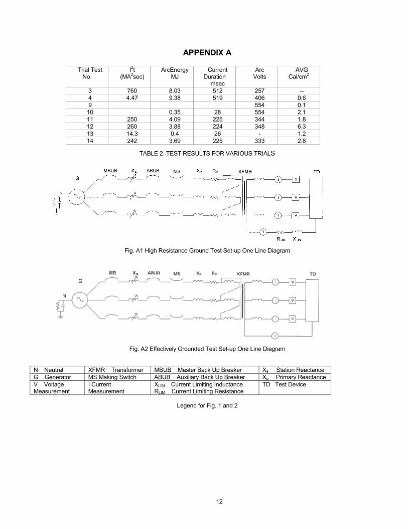
APPENDIX A
TABLE 2. TEST RESULTS FOR VARIOUS TRIALS
Fig. A1 High Resistance Ground Test Set-up One Line Diagram
Fig. A2 Effectively Grounded Test Set-up One Line Diagram
N Neutral XFMR Transformer MBUB Master Back Up Breaker Xs Station Reactance G Generator MS Making Switch ABUB Auxiliary Back Up Breaker Xp Primary Reactance V Voltage Measurement
I Current Measurement
XLIM Current Limiting Inductance RLIM Current Limiting Resistance