THE EVALUATION OF TRANSMISSION EFFICIENCY AND COUPLING LOSS FACTOR OF STRUCTURAL JUNCTIONS Y. TSO C4I AUGUST 1993 '2( DTIC ? •~E1,.ECTE I N OVIL819S E _ I APPRVED QCOMOMo of Australia FOR PUBLIC RELEAS! MATEtERIALS RESElIt ARCH LABORATOR)Y ' DSTO
Transcript
THE EVALUATION OF TRANSMISSION EFFICIENCYAND COUPLING LOSS FACTOR OF STRUCTURALJUNCTIONS
Y. TSO
C4I AUGUST 1993
'2(
DTIC? •~E1,.ECTE I
N OVIL819S
E _
I APPRVED QCOMOMoneItb of Australia
FOR PUBLIC RELEAS!
MATEtERIALS RESElIt ARCH LABORATOR)Y 'DSTO
"*1
I
* 1
I
STHE UNITED STATES NATIONALTECHNICAL INFORMATION SERVICE
IS AUTHORISED TO
FAPRODUC,(; AND StJ. THIS REPORT
II --1
Accesion For
NTIS CRA&IDTIC TABU. announced 0Justification ..............
By... .............Dist: ibution I
Availability Codes
Avail and /orDist Special
The Evaluation of TransmissionEfficiency and Coupling Loss Factor of
Structural functions
Y. Tso
MRL Technical ReportMRL-TR-93-1
Abstract
The evaluation of transmission efficiency of structural junctions forms an important partin the study of structure-borne noise as it provides the basis for identifying andquantifying the vibration paths in the structure. In this report, analytical methods forevaluating the transmission efficiency of structural junctions including plate-plate andplate-beam junction are described. The calculation of coupling loss factor from thetransmission efficiency of a junction for Statistical Energy Analysis (SEA) is alsodescribed. Sample calculations of transmission efficiencies on a number of structuraljunctions are presented. It is found that for typical naval ship constructions that consistof plates coupled to light thin beams, the elastic vibrations of the beams have a significanteffect on the transmission efficiency.
93-28034i~fllllllll p1
DEPARTMENT OF DEFENCEDSTO MATERIALS RESEARCH LABORATORY
93 11 15 063
I
Published by
DSTO Materials Research LaboratoryCordite Avenue, MaribyrnongVictoria, 3032 Australia
Telephone: (03) 246 8111Fax: (03) 246 89990 Commonwealth of Australia 1993AR No. 008-252
APPROVED FOR PUBLIC RELEASE
Author
Y.K. Tso
Yan Tso obtained ai BSc degree in mechanical engineeringfrom the Polytechnic of Central London in 1977 and anMSc degree by research from the University of Bath, UK,in 1982. Prior to joining DSTO, he had researchexperience in the rollover stability and saftty aspects ofheavy vehicles. He joined MRL in 1991 and is currentlyworking on the applications of Statistical Energy Analysisto structure-borne noise transmission in naval ships.
I
I
-T
Contents
1. INTRODUCTION 7
2. MODELLING THE STRUCTURAL JUNCTIONS 82.1 Mathematical Expression for Vibration Waves 82.2 Boundary Conditions 12
The Evaluation of TransmissionEfficiency and Coupling Loss Factor of
Structural Junctions
1. Introduction
One of the limiting factors in the analysis of vibration transmission throughcomplex structures, such as naval ships, is the transmission across junctions anddiscontinuities in the structure where vibration waves are partially reflected andpartially transmitted. The wave transmission properties of a structuraldiscontinuity may be characterised by the transmission efficiency which is definedas the ratio between the transmitted wave power and the incident wave power.The transmission efficiency is an important parameter in the study of structure-borne noise since it provides the basis to identify and quantify the vibration pathsin the structure. This information enables appropriate vibration controltechniques to be applied. The transmission efficiency may also be used tocalculate the coupling loss factor for Statistical Energy Analysis (SEA). SEA is avery useful technique for analysing the average vibration levels of complexinterconnecting elements, such as ship structures, especially at high frequencies.
One of the early attempts to evaluate the transmission efficiency was carried outby Cremer (1948). His work included right-angled plate junctions subjected tooblique incident bending waves. Other authors (Wohle et al., 1981; Craven andGibbs, 1981; and Langley and Heron, 1990) have extended the analysis to includelongitudinal and transverse shear waves. The contribution of these vibrationwaves to structure-borne noise has been investigated by Lyon (1986). In theprevious studies involving transmission efficiency of plate-beam structures, thestiffening beam was modelled by using conventional beam theory and the effect ofbeam vibration was neglected. While this so called "blocking mass" approachmight be valid for thick heavy beams, there are situations where elastic vibrationsof the beam have to be considered. For example, in plate-beam structures typicalof ship constructions, the web thickness may be of the same order as the plate andhence the effect of web vibration has to be accounted for in the evaluation oftransmission efficiency.
SD
In this report, analytical methods for evaluating the transmission efficiency ofstructural junctions typical of those found in ship constructions are described.The effect of elastic vibrations of the beam in a plate-beam junction is investigatedby modelling the beam as a finite plate coupled to a system of semi-infiniteplates. Samples of calculations for a number of junctions are presented.
2. Modelling the Structural Junctions
2.1 Mathematical Expression for Vibration Waves
Figure I shows a schematic diagram of plate-plate junction which consists of nplates coupled along a line. The plates are assumed to be infinite along the y andx1 to x. directions. It is further assumed that the plates are thin so that theboundary conditions can be applied on the plate centreline. Plate 1 is subjected toan oblique incident wave which can be either bending (B), longitudinal (L) ortransverse shear (T). The incident wave is partially reflected and partiallytransmitted at the junction as bending, longitudinal and transverse shear waves asshown. To study the mechanism of wave transmission at a junction, it isconvenient, as a first step, to consider the elastic deformations due to thesereflected or transmitted waves in an arbitrary plate. Figure 2 shows the platedeformations u, v and w along a set of local co-ordinates x, y and z respectively.Using thin isotropic plate theory, the following governing equations of motion forplate deformations may be derived (see Love, 1927, p496).
p = material density,g = Poisson's ratio,h = plate thickness,E = Young's modulus.
JiS
Xn.•
Y
IB
•1 " Incident wave
T OE -. 1_SB Reflected/X
Transmitted T Lr waves
reflcte wae
• B - Bending
L - LongitudinalT"- Transverse shear
X2
Figure 1: Schematic diagram of a plate-plate junction.
x
iUBwv
Figure 2: Co-ordinate system of an arbitrary plate showing transmitted/reflected waes,
plate displacements and junction forces and moment.
t9
The in-plane wave equations are functions of the plate deformations u and v. To
obtain a solution for these equations, one can make use of the velocity potential*and stream function V defined as follows (a detailed discussion on the use ofvelocity potential and stream function to analyse vibration waves is given byCremer et al., 1988, p 138):
u = -aýl ax~ l,(4)
v = -/+ /ax. (5)
Using equations (4) and (5), each of the in-plane wave equations is reduced to afunction of one dependent variable (* or iV) only:
V20-[p(l-A 2 )/ E]La2O/at 2 =0, (6)
V2 'P-[2p(+jU)/fE]a 2 • /at 2 =0. (7)
The general solutions to equations (1), (6) and (7) may be expressed as:
w = W exp (kBX x + kBy+joat), (8)
4 = P exp (k. + kLyY + j(t), (9)
y = TP exp (kTr x + kTYy + joet). (10)
The velocity potential 0 is associated with longitudinal waves while the streamfunction W with transverse shear waves. For the solutions to be valid, thefollowing conditions must be satisfied (these conditions can be obtained bysubstituting equations (8), (9) and (10) into equations (1), (6) and (7) respectively):
-(ka2 +k' k)=+1l2pwa2 (1-p2 )/Eh2 ]•2 = +k2, (11)
-(ku +k2 )=[pC02(l- 2)/E]=kL, (12)
-(k2 +k2 ) = [2p2(1+)/El= k2, (13)
where kB, kL and kT are the bending, longitudinal and transverse shear wavenumbers respectively. Snell's law states that the trace velocity of all wave types atthe junction must be the same. This implies that the y - component of wavenumbers (i.e. k.., kL, and kr.) for the reflected and transmitted waves of all platesmust be the same as that of the incident wave. The x - component of wavenumbers may be determined from equations (11) - (13). For bending waves,equation (11) yields four roots, the negative imaginary root and the negative realroot must be selected since they represent propagating and decaying wavesrespectively in the positive x - direction (i.e. away from the junction). Similarly,the solutions for longitudinal and transverse shear waves must be negativeimaginary. Equations (4), (5) and (8)-(10) give the elastic deformations of theplate, u, v and w. By expressing the x and y - components of wave numbers interms of the reflection/transmission angles y., 1L and yr, the plate deformationsmay be written as:
10
u =[jkL0coSTL exp(-jkLXCoSyL )-jk•'Psin yr exp(-jkTxcosyT )]
exp(ky + j4),(14)
v = [-jkL~sinyL exp(-jkLxcosTL )- jkr'PcosyT exp(-jkTXcosyT )]
exp(kvy + im)),(15)
w = {W, exp(-jkx cos y8 ) + W2 exp[ -kB.x,(1 + sin 2 y7)1) exp(kyy + jo)t), (16)
where k. is the y - component of incident wave number. The last exponentialfactor on the right hand side of the above equations represents the y - directiondependency and time dependency of the displacement amplitudes. These factorsare exactly the same for all wave types and will be omitted in the subsequentexpressions for simplicity. The reflection/transmission angles may be expressedin terms of the incident angle using the Snells law as discussed earlier:
k. sin y. = kL sin yL = kT sin YT = k sin a, (17)
where cx is the incident angle and k is the incident wave number. Note that theincident wave can be either bending, longitudinal or transverse shear. Equations(14) - (16) can be further simplified by introducing the complex wavedisplacement amplitudes defined as follows:
4B = W1, 4BN = W2, (18), (19)
4L = jkL 4>, 'T = jkT TP, (20), (21)
4B and OBN represents the complex wave amplitudes of the travelling and decayingbending waves respectively while 4L and 4T denote the amplitudes of thelongitudinal and transverse shear waves. Using equations (17) - (21), the platedeformations may be expressed as:
v = -4L [sin c / (kL / k)]exp(-jkR LX)-r I RT / (kT /k)Jexp(-jkRrx), (23)
w = k. exp(- jkRgx) + 4gN exp(-kRONX), (24)
where RD = 41(kA•) 2-sin2kl, (25)
D = B, L or T depending on the wave type,
RaN = q[(ko /k) 2 + sin2ct]. (26)
In equation (25), if the quantity inside the square root is negative, the exponentialterm representing the travelling wave in the wave equations becomes a realquantity and wave propagation cannot exist. One must then replace the quantity
11
'J[(k,,•)2-sin2t] by -.t[sin2a -(kjk)2] in the solution of wave amplitudes. For plate1, the deformations must also include the components of incident wave. Theelastic deformations due to the incident wave may be obtained in a similarmanner as that of the reflected/transmitted waves. The only difference being thatthe positive imaginary solution of the wave numbers in equations (11) - (13) mustbe selected since the incident wave propagates towards the junction. For thepurpose of evaluating the transmission efficiency, the incident wave may beconsidered as having a unit amplitude. Hence, for an incident bending wave, theelastic deformation is:
t 8 = exp (j k x cos a), (27)
for a longitudinal wave,
uL - cos Oa exp (jkLX COS 0)01 (28)
vL- -sin a [exp (jkL x cos )], (29)
and for a transverse shear wave,
uT = - sin cc [exp (j kT x cos a)], (30)
vT = cos a [exp (j kT x cos a)]. (31)
Superscripts B, L and T denote the type of incident wave. If follows from theabove analysis that the elastic deformations of each plate in the junction areexpressed in terms of four unknowns representing the complex wave amplitudes,namely, the amplitudes for longitudinal and transverse shear waves, as well asthe travelling and decaying bending waves. Hence, in a junction that consists of itcoupled plates, there are 4n unknowns to describe the wave motion. Theseunknowns may be solved by the appropriate boundary conditions.
2.2 Boundary conditions
2.2.1 Plate-plate junction
To consider the boundary conditions at a junction, it is convenient to introducethe subscript i to denote the plate number (i = 1, 2,...n). The compatibility of platemotions requires that the displacement components of all plates along a set ofreference co-ordinates (e.g. x,, y and z,) at the junction must be the same. Inaddition, the rotation about the y axis of all plates should be equal. The platerotation is given by:
61 = o,/lck. (32)
The displacement components of all plates (u• vi and w,) due to bending,longitudinal and transverse shear waves are given by equations (22) - (24). Forplate 1, the displacements must also include components of the appropriateincident wave as given by equations (27) - (31). Resolving the displacements of
12
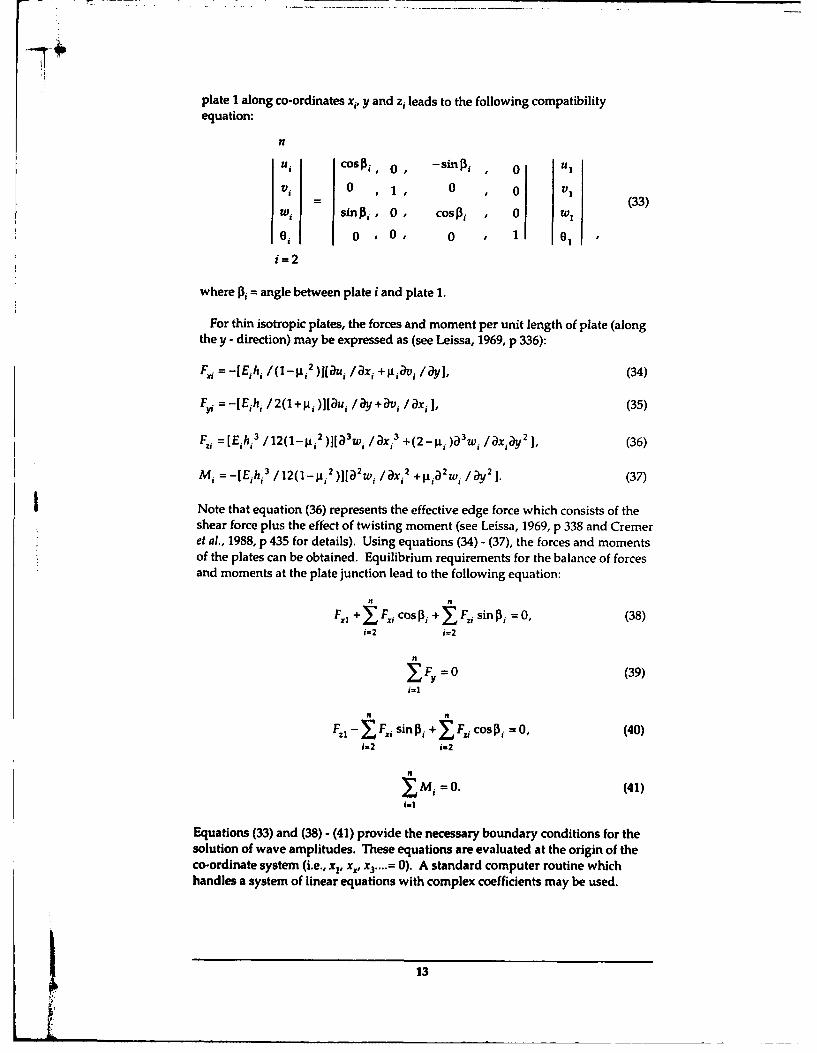
plate I along co-ordinates x,, y and zi leads to the following compatibilityequation:
nUi cosI31 , O, -sini , 0 u
V3 0 ,1, 0 , 0 V(
u, sinp,, 0, cosJp, , 0 w1
i 1 0 ,0 0 1 01
i=2
where { angle between plate i and plate 1.
For thin isotropic plates, the forces and moment per unit length of plate (alongthe y - direction) may be expressed as (see Leissa, 1969, p 336):
Note that equation (36) represents the effective edge force which consists of theshear force plus the effect of twisting moment (see Leissa, 1969, p 338 and Cremeret al., 1988, p 4 35 for details). Using equations (34) - (37), the forces and momentsof the plates can be obtained. Equilibrium requirements for the balance of forcesand moments at the plate junction lead to the following equation:
F.1 + F,, cos P, + EFi sin Ai = 0, (38)i=2 i=2
n
YEF, =0 (39)i=i
Is n
F., - F,, sinP, + YF cos P-=0, (40)i-2 i-2
IMi =0. (41).)i
Equations (33) and (38) - (41) provide the necessary boundary conditions for thesolution of wave amplitudes. These equations are evaluated at the origin of theco-ordinate system (i.e., x1, x,, x3 ....= 0). A standard computer routine whichhandles a system of linear equations with complex coefficients may be used.
j 13
KT2.2.2 Plate-beam junction (thick beam)
Figure 3 shows a schematic diagram of an infinite plate coupled to a thick uniformbeam. The thick beam assumption in the context of this report implies that noincident wave is transmitted to the beam. Also, it is assumed that the beamcentroid coincides with the shear centre and x, is a principal axis. It is furtherassumed that the boundary conditions can be applied to the origin of the co-ordinate system ( the validity of this assumption is discussed in section 5.2).Thus, the compatibility requirements for plate motions in this case are exactly thesame as for a plate-plate junction (equation (33)). However, the force and momentbalance equations ((38) -(41)) must be modified to allow for the torsional, bendingand inertia effects of the beam. For beams of high slenderness ratio (defined asthe ratio between the length and radius of gyration), the effects of sheardeformation and rotary inertia may be neglected (these effects have beeninvestigated by Langley and Heron, 1990) and the forces and moment balanceequations may be derived by the conventional beam theory.
YY
Fzb Fz F,
M~b
Beam Z
Vb w
Ii Plate
U
Ub S Zb 0
ZbXb b
Figure 3: A plate - thick beam junction showing the displacements and junction forcesand moments.
At the junction, the sum of the forces and moments due to all plates may beresolved along the beam co-ordinates xb, y, z, and expressed as the beam forcesand moment (see Figure 3):
The motions about the beam centroid ub, v. wb and 6b may be expressed in terms
of the elastic deformations of plate I:
ub = u cos ftb" w, sin Pb, (46)
Vb = V1, (47)
Wb = U, sin A.b+ w, COS [ b+ 01s, (48)
Oh= 0-, (49)
where Ob = angle between the beam and plate 1,S = distance between beam centroid and the junction.
The equilibrium of forces and moments at the junction must allow for thetorsional, bending and inertia effects of the beam. Consider the balance of forcesin the xb direction, the beam force FXb is augmented by the shear force as a result ofbeam bending in the x,-y plane (a similar argument exists for forces in the zbdirection). Summation of forces along the beam co-ordinates leads to thefollowing force balance equations:
-Fxb - Eblzb a4Ub /ay4 = mbC2 Ub 2 at 2 , (50)
yb= Mb2Vb /at 2 , (51)
-F EbI[3a4 Wb / ,y 4 = mb)2Wb /at,2 (52)
where mb = mass per unit length of beam,E, = Young's modulus of beam,10 = second moment of area of beam about axis xb,l• = second moment of area of beam about an axis parallel to z. and
passes through the beam centroid.
The variation in plate rotation 0, along they - axis causes the beam to twist andresults in a torsional moment. Consider the equilibrium of moments about a lineparallel to the y - axis and passes through the beam centroid:
-Mb + FOS+Tb,a2 b /4 2 = b a2% 0/at, (53)
15
tj
where Tb torsional stiffness of the beam,
lb moment of inertia per unit length about beam centroid.
Equations (33) and (50) - (53) represent the boundary conditions for a system ofplates coupled with a thick beam. Again, these are sufficient to permit solutionfor the wave amplitudes of interest.
2.3 Mathematical Modelfor a Thin Beam
Some engineering structures (e.g. ships, aircraft) quite often involve the use ofthin beams to reinforce plate elements. A thin beam in the context of this paperimplies that the beam thickness is of the same order as that of the plate elementand is therefore subjected to bending and in-plane waves. A schematic diagramof the structure is shown in Figure 4. The analysis of this type of structures maybe carried out by assuming that the thin beam behaves as a finite plate with wavestravelling in both the positive and negative x - directions. Referring back toequations (11) - (13), the solutions to wave motions of the finite plate in this casemust include the positive and negative roots. This results in eight unknowncomplex wave amplitudes (instead of four unknowns as in the case of an infiniteplate). By denoting the web as the second plate in a plate-plate junction, theexpressions for bending and in-plane waves may be derived in a proceduresimilar to those described in section 2.1:
The additional four unknowns in a plate - thin beam junction ,'aV, ý'JN2, ý.2 and4T. represent waves that travel in the negative x2 - direction of the finite plate.Four additional boundary conditions are thus required to solve the wave motions.These boundary conditions may be obtained by considering the force and momentbalance at the end of the finite plate. Substituting equations (54) - (56) into (34) -(37) and evaluating these equations at x, = L,, gives the forces and moment. Forthe structural junction shown in Figure 4, the forces and moment must vanish atthe free end of the plate.
Figure 5 shows a typical reinforced plate structure used in naval shipconstructions. The stiffening beam in this case consists of a web and flange. For
the analysis of vibration transmission, the flange may be considered as anotherfinite plate attached to the web and the flange with the web junction analysedusing a similar procedure as previously described. Alternatively, if the flange isthick compared with the web (say, or the order of twice the web thickness), onemay assume that the flange behaves as a thick beam attached to the web and theanalysis carried out in a procedure similar to those described in section 2.2.2.Figure 6 shows the forces and moments at the flange - web junction. The forceand moment balance equations (evaluated at x, = LW) may be expressed as:
16
Fx2 =mfa 2u2 /at2 (57)
FY2 = mf a2 v2 /it2 , (58)
F -aFlay = mMa2wf /at2 , (59)
M 2 + aM/Iay =a 202 at2 , (60)
where subscriptf represents the flange, and
iaFf /iay= Eff,I 4 W2 lOy 4 ,
aM, lay =aTya202 /ay 2.
Equations (57) - (60) represents the additional boundary conditions for thesolution of wave amplitudes.
ZI
X3 .•"- " - - - - - - "- Xl
~Z2
X2
Figure 4: Schematic diagram of a plate - thin beam junction.
Figure 5: Periodically stiffened panel.
17
2 FzF. 2y
Figure 6: A flange - wenb junction sowging displacmntsforces and mments.
3. Transmission and Reflection Efficiencies
The above analysis solves the wave amplitudes of plate - plate and plate - beamjunctions and leads to the calculation of wave power. The wave power per unitlength of a junction subjected to normal waves (perpendicular to the junction)may be expressed as the energy per unit area multiplied by the group velocity (seeCremer et al., 1988 p 109). For oblique waves, the expression must be modified bymultiplying it with the cosine of the wave angle since it is the projected length ofthe boundary line that effectively intercepts the wave. Figure 7 shows theinterception of an oblique incident wave for a plate - plate junction. Recall thatthe incident wave has a unit amplitude, the power due to an incident wave at anangle a is given by:
PINC = mI Oc.c cos a. (61)
Similarly, the transmitted/reflected power may be expressed as:
Pi = mi I to IO 2oc coS.D (62)
The transmission/reflection angle yi may be expressed in terms of the incidentangle a using Snell's law (equation (17)). The power expression thus becomes:
p•i =Miltl DiJ 0c,(klko,)Re[k•j/k)-sin 2 al, (63)
where m, = mass per unit area of plate i,D = B, L or T depending on the wave type,c., = group velocity of plate i,
= 2 q, for bending waves,= c.I for longitudinal waves,= cri for transverse shear waves.
-A
Incident wave
plate I !
Junction
Plate 2
Figure 7: Interception of an oblique incident wave at a junction.
Note that for bending waves, the transmitted or reflected power in a plate isdetermined by the far field travelling waves only. The near field waves decayexponentially along the direction x, and carry no time averaged power. Also, nopower is transmitted by a finite plate.
The transmission/reflection efficiency is defined as the ratio of thetransmitted/reflected wave power to the incident wave power and is a function ofthe incident angle ct:
Fý (a) = PM / PNC, (64)
where q and r represent the wave type of the incident and generated wavesrespectively, and i represents the carrier plate of the generated waves.Conservation of energy requires that the sum of all transmission and reflectionefficiencies to be equal to one.
4. Coupling Loss FactorThe coupling loss factor used in SEA defines the amount of energy flow from oneelement to the other. It can be shown (Lyon, 1975, p 91) that for two coupled sub-systems, the power lost by sub-system I due to coupling to sub-system 2 isproportional to the energy of sub-system I and may be expressed in terms of thecoupling loss factor as follows:
P12 -"wi1 (E), (65)
where<E1>, - time averaged energy of sub-system 1,v112 = coupling loss factor between sib-systems I and 2.
19b
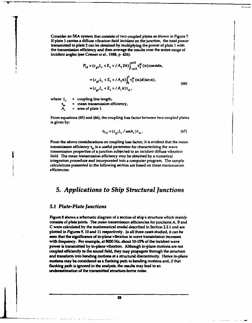
Consider an SEA system that consists of two coupled plates as shown in Figure 7.If plate I carries a diffuse vibration field incident on the junction, the total powertransmitted to plate 2 can be obtained by multiplying the power of plate I withthe transmission efficiency and then average the results over the entire range ofincident angles (see Cremer et al., 1988, p. 426):
-/Z
P12 = (c 1 LC < Ei >/AI 2x) 11 (ct)cos oia.
=(cIL€ < E >1 IAX)o (a)d(sin o),
(66)=(c,,L, <E, >/Alx)-t,0
where L, = coupling line length,= mean transmission efficiency,
A1 = area of plate 1.
From equations (65) and (66), the coupling loss factor between two coupled platesis given by:
'112 = (c,1 Lc /c•orAO)i., (67)
From the above considerations on coupling loss factor, it is evident that the meantransmission efficiency t, is a useful parameter for characterising the wavetransmission properties of a junction subjected to an incident diffuse vibrationfield. The mean transmission efficiency may be obtained by a numericalintegration procedure and incorporated into a computer program. The samplecalculations presented in the following section are based on mean transmissionefficiencies.
5. Applications to Ship Structural Junctions
5.1 Plate-Plate Junctions
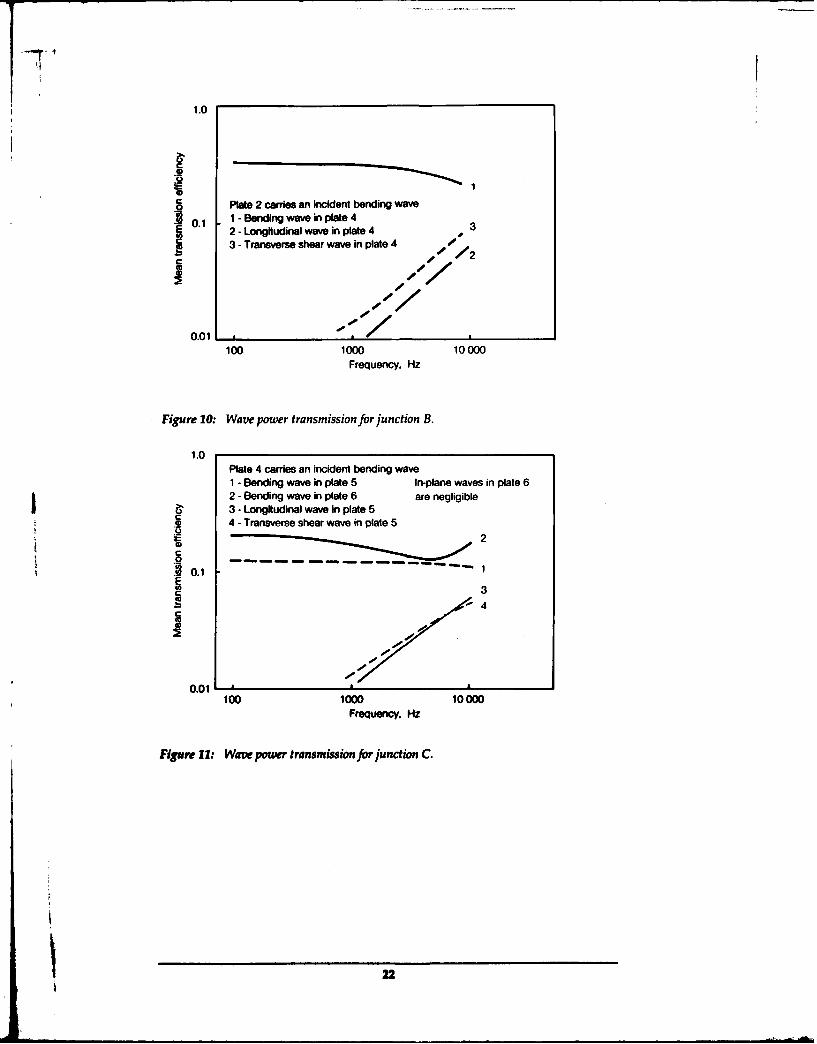
Figure 8 shows a schematic diagram of a section of ship's structure which mainlyconsists of plate joints. The mean transmission efficiencies for junctions A, B andC were calculated by the mathematical model described in Section 2.2.1 and areplotted in Figures 9, 10 and 1I respectively. In all three cases studied, it can beseen that the significance of in-plane vibration in wave transmission increaseswith frequency. For example, at 8000 Hz, about 10-15% of the incident wavepower is transmitted by in-plane vibration. Although in-plane motions are notcoupled efficiently to the sound field, they may propagate through the structureand transform into bending motions at a structural discontinuity. Hence in-planemoions may be considered as a flanking path to bending motions and, if thatRanking path Is Ignored in the analysis, the results may lead to anunderestimation of the transmitted structure-borne noise.
20
7512 mm
10 MM
Figure 8: Schematic diagram of a ship's section.
1.0Plate 1 carres an kident bending waveI - Bending wave in plate 2 4. Longitudinal wave in plate 32 - Bending wave in plate 3 5 -Transverse shear wave in plate 23 - Longitudinal wave in plate 2 6 - Transverse shear wave in plate 3
0111 6
3
0.01100 1000 10000
Frequency, Hz
Figure 9: Wam power transmission for junction A.
21
1.0
Plate 2 carries an incident bending wave
0.1 1 - Bending wave in plate 42 - Longitudinal wave in plate 4 3
I 3-Transverse shear wave in plate 4 O X2
0.01, _ ,__ __/
100 1000 10000
Frequency, Hz
Figure 10: Wave power transmission for junction B.
1.0Plate 4 carries an incident bending wave1 - Bending wave in plate 5 In-plane waves in plate 62 - Bending wave in plate 6 are negligible
I" 3 - Longitudinal wave in plate 5"4 - Transverse shear wave in plate 5
,,-2
C
S.• ~~0.1"- " 'E03C3
0.01100 1000 10000
Frequency, Hz
Figure 11: Wave power transmission for junction C.
22
5.2 Plate-Beam Junctions
The mathematical models for a thick beam (Section 2.2.2) and a thin beam(Section 2.3) coupled to thin plates were applied to the plate-beam junction shownin Figure 12. Since the beam thickness chosen in this example is the same as theplate, the beam would vibrate due to the incident wave and it is reasonable toargue that the thin beam model would give a more accurate prediction of thetransmission efficiency. Figure 13 shows the bending wave transmissionefficiency of the junction calculated by both models. The thick beam modelpredicts a low-pass characteristic of the plate-beam junction and underestimatesthe transmission efficiency at frequencies above 500 Hz. The effect of resonantbending frequency of the thin beam on wave transmission can be observed.
As a second example on plate-beam junctions, the beam thickness in Figure 10 isincreased to 20 mm. Figure 14 shows the calculated transmission efficiency.Below 1 kHz, the agreement between the thick beam model and the thin beammodel is reasonable. At higher frequencies, the thin beam model predicts a highertransmission efficiency, possibly due to the effect of plate resonance. It should benoted that the mathematical models used in this report are based on a thin platetheory and the assumption that the boundary conditions can be applied on thebeam/plate centreline. These assumptions may not be justified at highfrequencies where the cross sectional dimensions of the junction is not negligiblecompared with the bending wavelength. Cremer et al. (1988, p 115) suggestedthat the thin plate theory may be used if the bending wavelength is longer thansix times the plate thickness. For the present example, this converts to afrequency of approximately 26 kHz. The effect of plate offset from the centrelineof a thick beam may be considered by modifying the compatibility andequilibrium equations. This approach has been carried out and reported byLangley and Heron (1990). Despite the assumptions used in the models, thepresent analysis shows that the conventional heavy beam theory may lead to aserious underestimation of the transmission efficiency when applied to thin beamjunctions.
6. Conclusions
Analytical methods for evaluating the transmission efficiency of structuraljunctions have been presented. The mean transmission efficiency may be used toidentify and quantify vibration transmission paths in a junction. A study of themean transmission efficiency of plate junctions shows that the effect of in-planemotions is significant in structure-borne noise transmission, especially at highfrequencies. For structural junctions that consist of a thin beam, the elasticvibrations of beam plays an important part in wave transmission and should beconsidered in the analysis of structure-borne noise.
23
S I-10 mm200 mm
10 mm
- -- -Figure 12: A simple plate- thin beam structure.
1.0
Thin beam theory
0
C.223
C
Thick beam theory
f - Natural bending frequency
0.01100 1000 10000
Frequency, Hz
Figure 13: Bending wave transmission for a plate - thin beam junction.
424
1.0
Thin beam theory
S0.1
fl f22
Thick beam theoryf -Natural bending frequency
100 1000 10000Frequency. Hz
Figure 14: Bending wave transmission for a plate - thick beam junction.
i
7. References
Craven, P.G. and Gibbs, B.M. (1981). Sound transmission and mode coupling atjunctions of thin plates, part 1: representation of the problem. Journal of Sound andVibration 77(3), pp. 417-427.
Cremer, L. (1948). The propagation of structure-borne sound. Department ofScientific and Industrial Research Report No. 1, Series B.
Cremer, L., Heckl, M. and Ungar, E.E. (1988). Structure-borne sound. Berlin:Springer-Verlag.
Hecki, M. (1961). Wave propagation on beam-plate systems. The Journal of theAcoustic Society of America 33(5), pp. 640-651.
Langley, RIS. and Heron, K.H. (1990). Elastic wave transmission throughplate/beam junctions. journal of Sound and Vibration 143(2), pp. 241-253.
Leissa, A.W. (1969). Vibration of plates. NASA Special Report 160.
Love, A.E.H. (1927). A treatise on the mathematical theory of elasticity. Cambridge
Univenity Press.
25
Lyon, R.H. (1975). Statistical energy analysis of dynamical systems: theory and
applications. MIT press. Cambridge, Massachusetts.
Lyon, R.H. (1986). In-plane contribution to structural noise transmission. NoiseControl Engineering Journal 26(1), pp. 22-27.
Nilsson, A.C. (1976). Wave propagation in simple hull-frame structures of ships.Journal of Sound and Vibration 44(3), pp. 393-405.
W6hle, W., Beckmann, Th. and Schreckenbach, H. (1981). Coupling loss factorsfor Statistical Energy Analysis of sound transmission at rectangular structural slab
joints, part 1. Journal of Sound and Vibration 77(3), pp. 323-334.
26
12
Appendix
List of Symbols
Ai area of plate i
B bending wave
CBec•IcTi bending, longitudinal and transverse shear wavevelocities of plate i
cgi group velocity of plate i
D subscript to denote bending (B), longitudinal (L) andtransverse shear wave (T)
EjEb,•E elastic modulii of plate i, beam and flange
<Ei> time averaged energy of sub-system i
FXi,Fyi,Fzi component of internal plate forces per unit length inthe x,, y and zi directions of plate i
hi thickness of plate i
I second moment of area of beam about axis xb
lzb second moment of area of beam about an axis parallelto zb and passes through the beam centroid.
If second moment of area of flange about axis x2
JIbJf moment of inertia per unit length about longitudinalcentroidal axis of beam and flange
subscript to indicate plate/sub-system number(i = 1, 2,3 ..... n)
j complex operator
k wave number of incident wave
ky y - component of incident wave number
ksX'kB, ksk x and y - components of wave numbers for bending.longitudinal and transverse shear waves
kLykT,ekT,
kasfk,,kTky bending, longitudinal and transverse shear wavenumbers of plate i
27
I
L longitudinal wave
iLC length of coupling line at a junction
SL. width of web
Mi internal bending moment per unit length of plate i,the moment vector is in the y - direction
SM1 , M! moments per unit length about longitudinalcentroidal axis of beam and flange
mb,?m/P mass per unit length of beam and flange
mi mass per unit area of plate i
n number of plates in a junction
PINC power of incident wave
PDI transmitted or reflected wave power of plate i
P12 power lost by sub-system 1 due to coupling to sub-system 2
q, r superscripts to indicate wave type of incident andgenerated waves respectively
RBi,R i,RTi parameters to yepresent the cosine function of waveangle for bending, longitudinal and transverse shearwaves of plate i as defined by equation (25)
RBNi parameter to represent the cosine function of waveangle for the near field bending wave of plate i asdefined by equation (26)
S distance between the beam centroid and the junction
T transverse shear wave
TfTf torsional stiffness of beam and flange
t time
ui displacement of plate i in the x, - direction due totransmitted or reflected waves
uL, uT displacement of plate I in the x - direction due toincident longitudinal and transverse shear waves
28
vi displacement of plate i in the y - direction due totransmitted or reflected waves
VL, vT displacement of plate I in the y - direction due toincident longitudinal and transverse shear waves
Wi displacement of plate i in the z, - direction due totransmitted or reflected waves
displacement of plate I in the z - direction due toincident bending wave
xi'y, zi system of co-ordinates of plate i
Xb,,Y,Zb system of co-ordinates of beam
a incident wave angle
angle between plate I and plate i
angle between plate I and beam
* velocity potential
"YB,'L'"Y wave angles of transmitted/reflected bending,longitudinal and transverse shear waves
T112 coupling loss factor between sub-system I and 2
A, Poisson's ratio of plate i
0i angular displacement of plate i about the y - axis
,[(a) transmission/reflection efficiency as a function of theincident wave angle, the efficiency is defined as theration of the transmitted/reflected wave power to theincident wave power
In mean transmission/reflection efficiency
0 dcircular frequency
4Bi •8N AU t, complex wave displacement amplitudes for travellingand decaying bending waves, as well as longitudinaland transverse shear waves of plate i travelling in thepositive x, - direction
•, ,M ,•'L,, •, same definition as above but with waves travelling inthe negative x, - direction
W stream function
29
_ k
T
SECURITY CLASSIFICATION OF THIS PAGE UNCLASSIFIED
REPORT NO. AR NO. REPORT SECURITY CLASSIFICATION
MRL-TR-93-1 AR-008-252 Unclassified
The evaluation of transmission efficiency and coupling loss factor of structural junctions
AUTHOR(S) CORPORATE AUTHORY.K. Tso DSTO Materials Research Laboratory
PO Box 50Ascot Vale Victoria 3032
REPORT DATE TASK NO. SPONSORAugust, 1993 DST 90/134 DSTO
FILE NO. REFERENCES PAGESG6/4/8-4203 11 30
CLASSIFICATION/LIMITATION REVIEW DATE CLASSIFICATION/RELEASE AUTHORITYChief, Ship Structures and Materials Division
SECONDARY DISTRIBUTION
Approved for public release
ANNOUNCEMENT
Announcement of this report is unlimited
KEYWORDS
Structure-borne noise Elastic vibrations Statistical energy analysisCoupling loss factors Elastic waves Structural junctionsSEA
ABSTRACT
The evaluation of transmission efficiency of structural junctions forms an important part in the study ofstructure-borne noise as it provides the basis for identifying and quantifying the vibration paths in the structure.In this report, analytical methods for evaluating the transmission efficiency of structural junctions includingplate-plate and plate-beam junction are described. The calculation of coupling loss factor from the transmissionefficiency of a junction for Statistical Energy Analysis (SEA) is also described. Sample calculations oftransmission efficiencies on a number of structural junctions are presented. It is found that for typical naval shipconstructions that consist of plates coupled to light thin beams, the elastic vibrations of the beams have asignificant effect on the transmission efficiency.
SECURITY CLASSEP1CATION OF THIS PAGEUNCLASSIFIED
V
The Evaluation of Transmission Efficiency and Coupling LossFactor of Structural Junctions
Y. Tso
DISTRIBUTION LIST
Director, MRLChief, Ship Structures and Materials DivisionDr J.C. RitterY. TsoMRL Information Services
Chief Defence Scientist (for CDS, FASSP, ASSCM) 1 copy onlyDirector, Surveillance Research LaboratoryDirector (for Library), Aeronautical Research LaboratoryDirector, Electronics Research LaboratoryHead, Information Centre, Defence Intelligence OrganisationOIC Technical Reports Centre, Defence Central LibraryOfficer in Charge, Document Exchange Centre 8 copiesArmy Scientific Adviser, Russell OfficesAir Force Scientific Adviser, Russell OfficesNavy Scientific Adviser - data sheet onlyScientific Adviser, Defence CentralDirector General Force Development (Land)Senior Librarian, Main Library DSTOSLibrarian - MRL Sydney - data sheet onlyLibrarian, H BlockUK/USA/CAN/ABCA Armies Standardisation Rep., c/- DATD (NSO) 3 copiesLibrarian, Australian Defence Force AcademyCounsellor, Defence Science, Embassy of Australia - data sheet onlyCounsellor, Defence Science, Australian High Commission - data sheet onlyScientific Adviser to DSTC Malaysia, c/- Defence Adviser - data sheet onlyScientific Adviser to MRDC Thailand, c/- Defence Attache - data sheet onlyHead of Staff, British Defence Research and Supply Staff (Australia)NASA Senior Scientific Representative in AustraliaINSPEC: Acquisitions Section Institution of Electrical EngineersHead Librarian, Australian Nuclear Science and Technology OrganisationSenior Librarian, Hargrave Library, Monash UniversityLibrary - Exchange Desk, National Institute of Standards and Technology, USExchange Section, British Library Document Supply CentrePeriodicals Recording Section, Science Reference and Information Service, UKLibrary, Chemical Abstracts Reference ServiceEngineering Societies Library, USDocuments Librarian, The Center for Research Libraries, US
DNA, Department of Defence, Campbell Park Offices CP1-5-05, Canberra ACT