20
Brent Carlson EVLA System PDR (Correlator V2) December 4-5, 2001 1 Correlator

Brent Carlson EVLA System PDR (Correlator V2)December 4-5, 2001
1
Correlator

Brent Carlson EVLA System PDR (Correlator V2)December 4-5, 2001
2
Outline
• Requirements• Architecture• Technology• Software• Budget• Schedule• Installation

Brent Carlson EVLA System PDR (Correlator V2)December 4-5, 2001
3
Requirements• 16 GHz bandwidth (8 x 2 GHz bands).• 16,384 spectral channels/baseline (wideband), 0.25 million (narrower
w/recirculation).• 16 independently tunable digital sub-bands/baseband + N.B. radar
filter.• Flexible: tradeoff B.W. for freq. channels.• 2 banks of 1000 phase bins/baseline.• High performance, flexible dumping.• Very long baseline capable (>10k km baselines).• 1/16th sample digital delay tracking.• Baseband and sub-band multi-beaming…on the same data.• Simultaneous 1 GHz B.W. phased output on multiple sub-arrays.

Brent Carlson EVLA System PDR (Correlator V2)December 4-5, 2001
4
RequirementsDescription “Dream” Correlator Spec. Planned deliverable
No. of antennas 36 32, expandableBandwidth 4 x 2 x 2 GHz (16 GHz) 4 x 2 x 2 GHz (16 GHz)Freq. Resolution few Hz ... 10’s MHz 1 Hz ... 2 MHzNo. of independently tunable IF pairs at least 4, prefer 8 64, with digital sub-bandsNo. of frequency channels 1000 (full polarization per IF pair),
8000 total1024 W.B. (more w. recirc)
16384 W.B. total (more w. recirc)Frequency channel flexibility split flexibly among IFs,
select subset for writing
split flexibly among IFs and sub-bands,
select subset for writingFlexibility Frequency resolution: factors of 2
Flexible tradeoffs (#baselines, B.W.,#channels, pol’n, time res’n)
Interf. sub-arrays: 4 independentPhased sub-arrays: 4 independent
OkCan’t tradeoff baselines
at full bandwidthInterf. sub-array: unlimited.
Phased sub-arrays: 5Integration times 0.1 sec (less with tradeoffs) 0.011 sec (less with tradeoffs)Total data rates few tens of Mvis/sec several Gvis/secAutocorrelations all stokes parameters W.B. all stokes, SNR loss
S.B. all stokes, no SNR lossRFI as many channels as possible
106 dynamic range
automatic flagging
gating
Ok: 16,384...262,1444-bit sampling standard, up to 8-
bit sampling avail (d.r. depends onnoise+RFI)
post-corr. interference excision +facilitates post-corr. cancellation.
from antenna, external signalPulsar phase binning up to 1000 2 x 1000, min 15 �sec eachPhase Cal at least auto-spectra minimum 1 pCal extractor/IFDelay tracking 1/16th sample, 250 km baseline digital �1/32nd sample, 104 km+ bl

Brent Carlson EVLA System PDR (Correlator V2)December 4-5, 2001
5
Architecture• FIR filter banks followed by complex XF correlator:
– “Stitch” sub-bands together after correlation to yield wideband cross-corr.– Use small LO offsets in antenna to keep fringe rotators “wet”: fringe stopping, anti-
aliasing, artifact decorrelation, digital sub-sample delay tracking, VLBI.– Each poly-phase FIR independently programmable for flexibility…scientific req’t.
• Three main modules:– Station Board (2 x 2 GHz).– Baseline Board (64 baselines ea).– Phasing Board (48 stations, 2 sub-bands, 5 sub-arrays).
• Plus some 4 small interconnect modules…expandable, flexible.

Brent Carlson EVLA System PDR (Correlator V2)December 4-5, 2001
6
Architecture
MD
R-8
0
MD
R-8
0
MD
R-8
0
MD
R-8
0
MD
R-8
0
MD
R-8
0
MD
R-8
0
MD
R-8
0
MD
R-8
0
MD
R-8
0
MD
R-8
0
MD
R-8
0
MDR
-80
MDR
-80
MDR
-80
MDR
-80
MDR
-80
MDR
-80
MDR-80
MDR-80
MDR-80
MDR-80
MDR-80
MDR-80
MDR-8
0
MDR-8
0
MDR-8
0
MDR
-80
MDR-8
0
MDR-8
0
MDR-8
0
MDR
-80
MDR-8
0
MDR-8
0
MDR-8
0
MDR
-80
MDR-8
0
MDR-8
0
MDR-8
0
MDR
-80
4-StationComplex Mixer
+ 1st Stage
Adder
48-S
tatio
n Da
ta E
ntry
Con
nect
ors
-48 VDC to1.8V, 2.5VPOWERSUPPLY
Powe
rC
onne
ctor
MCBInterfaceModule
Fibre WDMDemodulators
Sub-band Distributor Backplane
BaselineEntryBackplane
StationDataFanoutBoard
PhasingBoardEntryBackplane
Network Switches
Host/Control
Computers;Archiving
Antennas:Receivers,Samplers,Fibre WDM
FOTS
PC/CPCI
TIMECODEGeneratorBox (TGB)
Reference Clock
Reference Time Tick
TIMECODE(s) + CLOCK(s)
Finalsynchronization
and VLBI recorderinterface
VLBIRecorder(s)
Phased outputfeedback
synchronization
To phased-VLAStation Board
input(s)
Baseline Board
PC/CPCI
PC/CPCI
-48 V DC to1.8V , 2.5VPOWERSUPPLY
MCBInterfaceModuleEt
hern
et
Fibre-OpticReceiverModule
DELAY
DELAY
FIRFilterBank
FIRFilterBank
Switc
hSw
itch
Timing
Station Board
Retiming/Drivers
8 'X
' Rec
ircul
atio
n Co
ntro
llers
8 'Y' Recirculation Controllers
8 x 8Correlator Chip
and LTA ControllerMatrix
MCBInterfaceModuleEt
hern
et
-48 VDC to1.8V, 2.5VPOWERSUPPLY
SERIALI/F(s)
4-StationComplex Mixer
+ 1st Stage
Adder
4-StationComplex Mixer
+ 1st Stage
Adder
4-StationComplex Mixer
+ 1st Stage
Adder
4-StationComplex Mixer
+ 1st Stage
Adder
4-StationComplex Mixer
+ 1st Stage
Adder
4-StationComplex Mixer
+ 1st Stage
Adder
4-StationComplex Mixer
+ 1st Stage
Adder
4-StationComplex Mixer
+ 1st Stage
Adder
4-StationComplex Mixer
+ 1st Stage
Adder
(5)Sub-array2nd-Stage
Adders
FIRFilterBank
Switc
h
Phasing Board
Master Slave 1 Slave 2 Slave 3
WidebandAutocorrelator
200 p
in ty
pe E
200 p
in ty
pe E
200 p
in ty
pe E
200 p
in ty
pe E
200 p
in typ
e E20
0 pin
type
E
4-StationComplex Mixer
+ 1st Stage
Adder
4-StationComplex Mixer
+ 1st Stage
Adder
PC/CPCI
Brent Carlson EVLA System PDR (Correlator V2)December 4-5, 2001
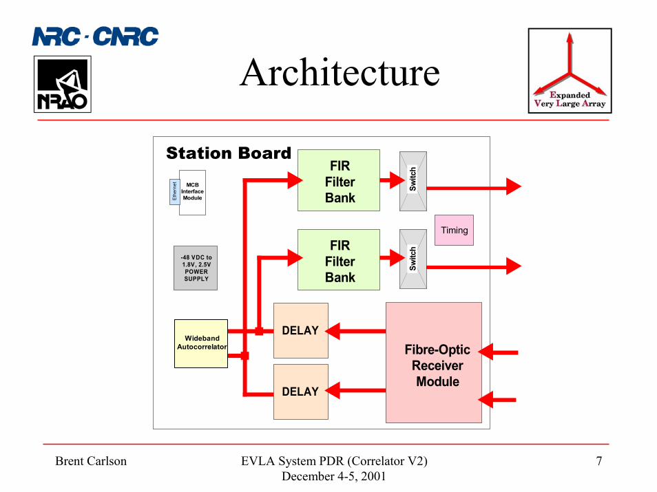
7
Architecture
-48 VDC to1.8V, 2.5VPOWERSUPPLY
MCBInterfaceModuleEt
hern
et
Fibre-OpticReceiverModule
DELAY
DELAY
FIRFilterBank
FIRFilterBank
Switc
hSw
itch
Timing
Station Board
WidebandAutocorrelator
Brent Carlson EVLA System PDR (Correlator V2)December 4-5, 2001
8
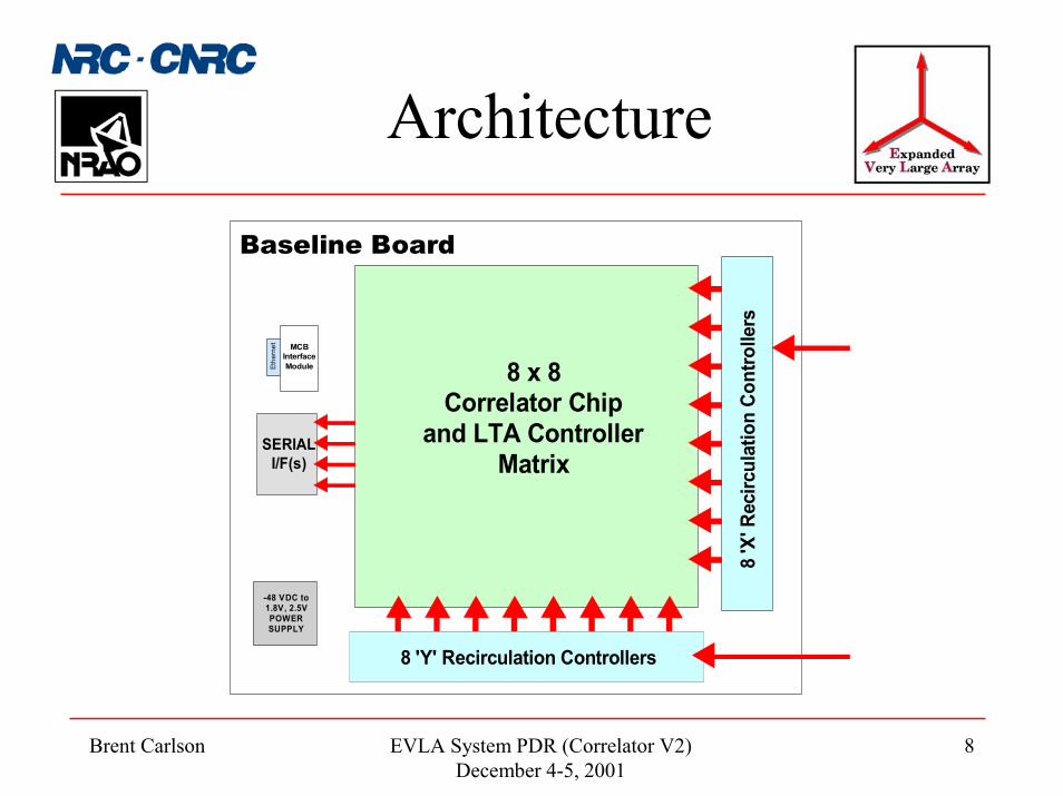
Architecture
Baseline Board
8 'X
' Rec
ircul
atio
n Co
ntro
llers
8 'Y' Recirculation Controllers
8 x 8Correlator Chip
and LTA ControllerMatrix
MCBInterfaceModuleEt
hern
et
-48 VDC to1.8V, 2.5VPOWERSUPPLY
SERIALI/F(s)

Brent Carlson EVLA System PDR (Correlator V2)December 4-5, 2001
9
Architecture
4-StationComplex Mixer
+ 1st Stage
Adder
48-S
tatio
n D
ata
Entry
Con
nect
ors
-48 VDC to1.8V, 2.5VPOWERSUPPLY
Powe
rCo
nnec
tor
MCBInterfaceModule
4-StationComplex Mixer
+ 1st Stage
Adder
4-StationComplex Mixer
+ 1st Stage
Adder
4-StationComplex Mixer
+ 1st Stage
Adder
4-StationComplex Mixer
+ 1st Stage
Adder
4-StationComplex Mixer
+ 1st Stage
Adder
4-StationComplex Mixer
+ 1st Stage
Adder
4-StationComplex Mixer
+ 1st Stage
Adder
4-StationComplex Mixer
+ 1st Stage
Adder
4-StationComplex Mixer
+ 1st Stage
Adder
(5)Sub-array2nd-Stage
Adders
FIRFilterBank
Switc
h
Phasing Board
4-StationComplex Mixer
+ 1st Stage
Adder
4-StationComplex Mixer
+ 1st Stage
Adder
Brent Carlson EVLA System PDR (Correlator V2)December 4-5, 2001
10
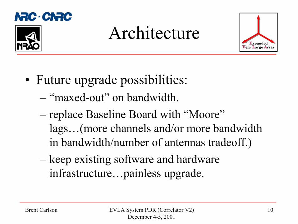
Architecture
• Future upgrade possibilities:– “maxed-out” on bandwidth.– replace Baseline Board with “Moore”
lags…(more channels and/or more bandwidth in bandwidth/number of antennas tradeoff.)
– keep existing software and hardware infrastructure…painless upgrade.

Brent Carlson EVLA System PDR (Correlator V2)December 4-5, 2001
11
Technology• 256 MHz system clock rate:
– FPGA and gate array tech. supports this.– Development tools (Mentor/Cadence) well-equipped for this
speed/complexity.– Can de-scope to 128 MHz on PCB (with 256 MHz interconnects) if
absolutely necessary.
• FIR filter:– Prototype in FPGA (power, $$). Convert to 0.18 �m gate array (AMIS).
Should be able to get 1024 taps. ($200k NRE, $50 ea, 10k qty). Claim that they use 1/5th the number of gates for same function as Xilinx.
• 2048-tap power estimate: 20 nW/MHz/gate * 300k gates * 256 MHz * 1.0 (switching fraction) = 1.5W

Brent Carlson EVLA System PDR (Correlator V2)December 4-5, 2001
12
Technology
• Correlator chip:– Original plan: develop full-custom 0.18 �m standard cell from
scratch ($900k NRE + $700k production).– Current plan: prototype with scaled-down (fewer lags) FPGA,
convert to gate array or standard cell afterwards. Pushes back technology freeze to latest possible date to take advantage of improvements…
• Power: 20 nW/MHz/gate * 0.5 million (hi-speed switching) gates * 256 MHz * 0.75 transition fraction = 1.9W (2.5W with 1.0 transition fraction)

Brent Carlson EVLA System PDR (Correlator V2)December 4-5, 2001
13
Software
• Use hierarchical approach (mirrors AMCS):– 1 SCC and 1 BCC (perhaps one platform).– Use NRAO MIBs on boards.
• Backend software/configs…

Brent Carlson EVLA System PDR (Correlator V2)December 4-5, 2001
14
Software
PhBB0
SB0 SB1 SB2 SB15 SBCal SBrad
PhBB1
PhBB2
PhBB3
PhBB4
PhBB5
PhBB6
PhBB7
slot_factorslot_number
BBstr(a...b)
SB_LOfshiftSRC_coord
BB_width
filter_parms
binning_parmsint_timepolarizationgatingpulsar_parmsphasing_parms
delay_parms
RFI_control
data_parmsPCal_parmsstats_parms
copy_control
autocorr_parms
SRC_coord
array_center
array_center
antenna_IDantenna_coords
BBstr[16](a...b)
wb_autocorr_parmswb_stats_parms
BBLO[16]BBsideband[16]
Sub-band ControlParameters
Physical BaseBandControl Parameters
A "station input": shares TIMECODE, DUMPTRIG etc.
Station Board Station Board Station Board Station Board
Noise-calfilter
Radarfilter
BBbits[16]BBcoding[16]
requant_parms
antenna_coords
recirc_parms
Sub-bandfilters (16)
num_spec_chansnum_pol
Indicates what we wantthe correlator to do withthis sub-band, but not howit is done.
physical_SBout
Brent Carlson EVLA System PDR (Correlator V2)December 4-5, 2001
15
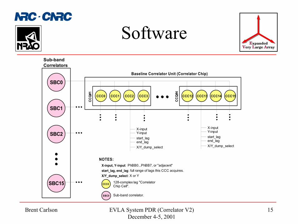
Software
SBC0
SBC1
SBC2
SBC15
CCC0 CCC1 CCC2 CCC3CC
Q#1
CCC12 CCC13 CCC14 CCC15
CCQ#
4
X-inputY-input
Sub-bandCorrelators
Baseline Correlator Unit (Correlator Chip)
start_lagend_lagX/Y_dump_select
X-inputY-inputstart_lagend_lagX/Y_dump_select
X-input, Y-input: PhBB0...PhBB7, or "adjacent"start_lag, end_lag: full range of lags this CCC acquires.X/Y_dump_select: X or Y
CCC0 128-complex lag "CorrelatorChip Cell".
SBC0 Sub-band correlator.
NOTES:

Brent Carlson EVLA System PDR (Correlator V2)December 4-5, 2001
16
Software
LocalResourceManager
LocalStation
ResourceTable
ConfigurationManager
ErrorMessageManager
ModelGenerator
DataManager
TimeManager
Low-LevelStatus and
DebugManager
FilterCoefficientGeneratorProgram
ISRModelServerTask
Model queue
ConfigurationTask
DataHandler
Task
Data queue
FPGA BootServerTask
DataReadout
Task
ErrorMessage
Task
TimeClientTask
S/WMonitor
Task
Low-Level
Status andDebugTask
StationBoard
MonitorTask
Delay& PhaseControl
Task
DUMPTRIGControl
Task
Configurationqueue
ConfigurationTable
H/W
H/W
H/W
H/W
H/W
H/W
ConfigurationServer
H/W
OSKernel
Station Board MIB (128)Station Control Computer (1)VCI-SCC
TGB MIB
10 msINT
SEM(dataready)
data
data
datadata
Errormess.
Errormess.
Errormess. time
configdata
configdata
configdataconfig
data
configdata
configdata
configdata time
Errormess. model
req.
configdata
configdata
linearmodels
linearmodels
configdata
model polynomials
ack.
Errormess.
Errormess.
triggerreq.
SEM(trigger)
modelreq.model+
delaymeas.
req.meas.
delay meas.
Errormess.
volt + temp +status readvolt+temp
messages
Errormess.
Errormess.
Errormess.
Errormess.
taskstatus
taskstatus
write
read
bootdata
ack.
time
config req + data
ack.time
time settingreq./ack.
status/functionreq.
ack, data
Errormess.
FPGA boot req + data
ack.
model genrequest
ack.
array/observationtime
FITS data fragments
resourcedata
resourcedata
Errormess.
status/function request
ack, data
Correlator Station Control Data Flow Diagram
widebandautocorrelations
resync
resource data
ack.
configrequest
ack.
H/W
requantizerthresholds
BaselineProcessing
PCs
statecnts

Brent Carlson EVLA System PDR (Correlator V2)December 4-5, 2001
17
BudgetEVLA Correlator, 32 Stations
Total Cost Breakdown ($12.17 million)
NRE+Miscl Dev.19% ($1.9M)
Contingencies13% ($1.64M)
Labour19% ($2.4M)
System Comps14% ($1.8M)
H/W Modules35% ($4.5M)
Could shave ~$1.3 million off this budget with cheaper cables and AMIS gate array for FIR (& corr chip).

Brent Carlson EVLA System PDR (Correlator V2)December 4-5, 2001
18
ScheduleDate MilestoneNov. 2/2001 Conceptual Design Review (CoDR). Design frozen.Q1, 2002 New personnel in place. Design tools in place. Training and design work
begins.Q1, 2004 Critical User Manuals in place. Device driver code can be written.Q2, 2004 Preliminary Design Review (PDR). Designs ready for prototype fabrication.Q1, 2005 Prototype test at the VLA starts.Q2, 2005 Prototype test at the VLA complete.Q3, 2005 Critical design review (CDR). Prototype testing complete. Ready for
procurement of production components and full production.Q2, 2006 Production model test and burn-in, system integration and test in Penticton, and
rack and cable installation begins at the VLA.Q4, 2006 Begin full installation at the VLA. Earliest possible start of installed correlator
testing.Q2, 2007 Earliest possible “beta” science data. (Middle of full installation schedule.)Q1, 2008 Correlator commissioning. Correlator fully on-line for observing. Continuing
debug support available.Q1, 2009 End of project. End of NRC debug support. Full handover to NRAO complete.

Brent Carlson EVLA System PDR (Correlator V2)December 4-5, 2001
19
Installation
Station Racks (12)
48 VDC Plant
48-Station Rack Layout: 1 Floor; 2 sub-racks per 7 ft rack (Nov. 20/2001)
3 Racks =2 sub-bandcorrelators
44 ft
44.5 ft
Air C
ondi
tione
r
Baseline Racks (24)
Air C
ondi
tione
r
Air C
ondi
tione
rAi
r Con
ditio
ner
Max cable length=36 ft (11 m)

Brent Carlson EVLA System PDR (Correlator V2)December 4-5, 2001
20
Summary
• Wideband, high-performance, flexible.• Expandable, re-configurable.• Painless upgrade path.• (0�10k+ km baselines).• $10 - $12 million (32 stations; another ~$6 million for 48
stations).• Start installation ~2006.• First “beta” science ~2007.• Completion 2008-2009.


![cPCI-DIO02 - DAQ SYSTEM · 2013-10-12 · [그림 3-2. cPCI-DIO02 ‘J2’ Box-header] The cPCI-DIO02 has the last 32 I/O (total 128) through ‘J1’ Box header connector. 3.3 Address](https://static.documents.pub/doc/80x56/5f897561b82e4d072e321911/cpci-dio02-daq-2013-10-12-ee-3-2-cpci-dio02-aj2a-box-header-the-cpci-dio02.jpg)


