RPT-PS-G0064 The Gemini Telescopes Project F. C. Gillett, M. Mountain, R. Kurz, D. A. Simons, M. Smith, T. Boroson March 22, 1996 GEMINI 8-M Telescopes Project GEMINI PROJECT OFFICE 950 N. Cherry Ave. Tucson, Arizona 85719 Phone: (520) 318-8545 Fax: (520) 318-8590
Transcript
RPT-PS-G0064
The Gemini Telescopes Project
F. C. Gillett, M. Mountain, R. Kurz, D. A. Simons,M. Smith, T. Boroson
The Gemini Telescopes Project is an international partnership of the U.S., U.K., Canada, Chile,Argentina, and Brazil to build two telescopes, one in the northern hemisphere and one in thesouth. The telescopes will achieve an unprecedented combination of light-gathering power andimage quality over the infrared, optical and ultraviolet spectral regions observable from theground. The facilities are intended to exploit the best natural observing conditions at the sites tocarry out a broad range of astronomical research programs undertaken by the Nationalcommunities of the partner countries. First light on Gemini-North is scheduled for 1998 and forGemini-south in the year 2000, with handover to operations in 2000 and 2001 respectively.
1. INTRODUCTION
The main scientific theme of the Gemini partnership is observing and understanding the originsand evolution of stars and planetary systems, of galaxies and of the universe itself. Toaggressively pursue this theme, four key scientific capabilities have been adopted for the GeminiTelescopes (Gemini Science Requirements, 1994);
1) Two 8 m diameter telescopes. One telescope will be located on Mauna Kea, Hawaii, andthe other on Cerro Pachon in Chile. All astronomical objects will be accessible to the Geminitelescopes, regardless of their location on the celestial sphere. The two telescopes are identical indesign to provide similar performance in programs spanning both hemispheres and to reducecosts.
The optics configuration for the Gemini telescopes is that of a 8-m diameter F/1.8 primary mirrorwith a 1.2 m diameter central hole made of Corning ULETM glass, together with a 1.02 mdiameter, articulated, SiC secondary mirror with a 0.168-m diameter central hole, providing anF/16 cassegrain focal plane 4 meters behind the primary mirror. The telescopes are designed forinterchangeable front ends with capacity to accomodate a future F/6 wide field cassegrainconfiguration.
2) Superb image quality. Both Gemini sites offer excellent seeing conditions and the intentis that the telescopes, including enclosure and tracking effects, degrade the best wavefront tiltcorrected atmospheric seeing image size by less than 15%. The minimum image sizes will beachieved at near IR wavelengths, and the resulting 2.2 m image quality requirement is 50%encircled energy within a diameter of 0.1 arcsec, including diffraction.
3) Versatile Optical/IR capabilities. The broad scientific goals of the Gemini partnershiprequire the Gemini telescopes to have high throughput from 0.3 m to at least 30 m. Thisincludes an optimized IR configuration with remotely switchable baffling for both near IR andoptical observations. A cassegrain focal station that permits simultaneous mounting of at leasttwo instruments, and a fibre and potentially a direct optical feed to an off-telescope high stabilityinstrument location within the telescope pier will be available.
4) Efficient/adaptable Observing. In order to exploit the best observing conditions to dohigh priority scientific observations, the Gemini facilities will be able to change rapidly betweenscientific instruments, and support a wide range of observing modes, including both "classical"and queue observing.
In the following sections, the approaches adopted by the Gemini project to achieve theserequirments are briefly summarized. Further information on the design and performance can befound in the associated references.
2. IMAGE QUALITY
Achieving the image quality requires careful attention to every aspect of the facility design,including water tunnel (Raybould, etal, 1994a) and super-computer (De Young and Charles,1995) modeling of the flow in and around the Gemini enclosure, thermal modeling of thetelescope and enclosure components and extensive optical and finite element analysis of thetelescope structure and optical system.
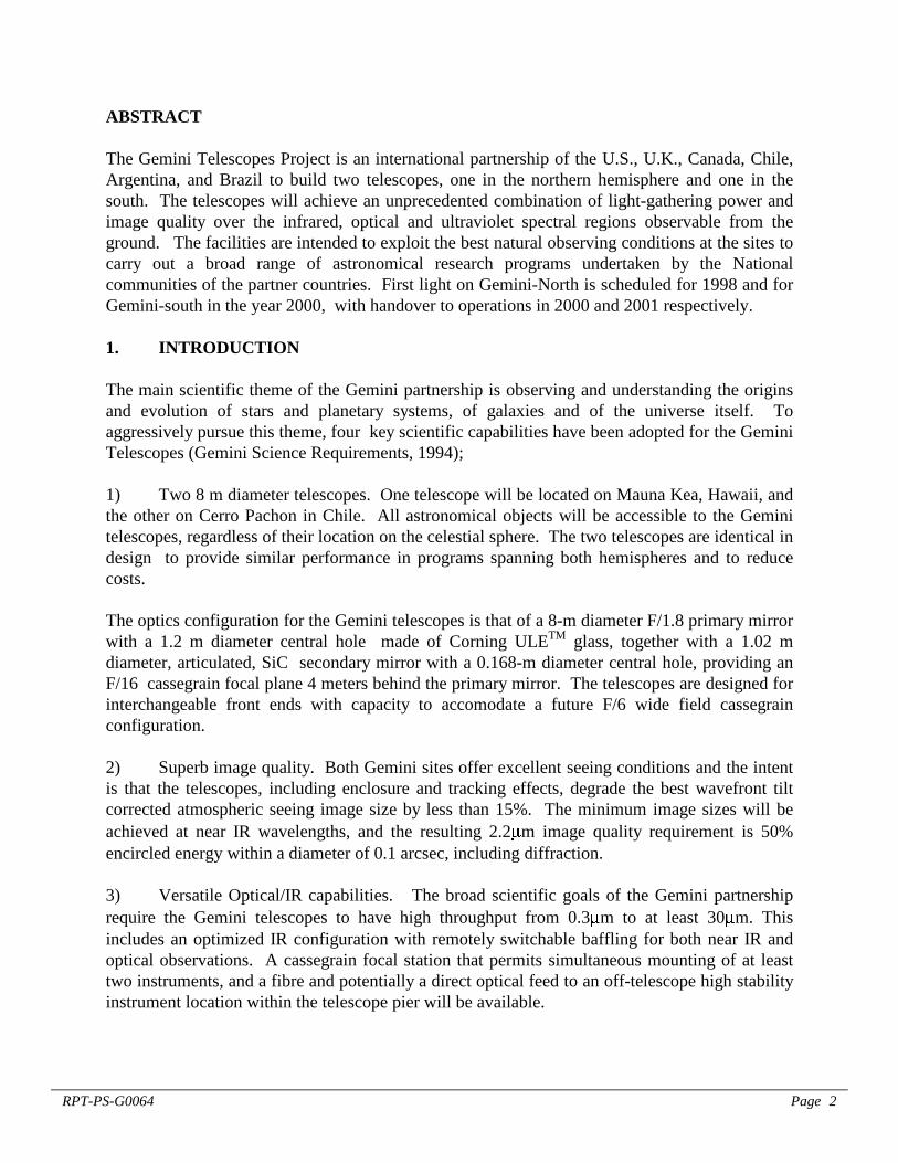
The enclosure, Figure 1, has large variable ventilation gates so the enclosure chamber can beflushed effectively by the wind or by an active ventilation system during observing. The controlbuilding is separated from the unheated enclosure and electronic boxes within the dome areactively cooled to minimize heat input to the chamber. The telescope elevation axis is 20mabove ground level, above the turbulent boundary layer (Raybould, et al,1994a).
Fig. 1 (above) The Gemini enclosure showing theventilation gates open on one side and location of the
control building.
Fig. 2 (right) The Gemini telescope with theInstrument Support structure (ISS) mounted at the
Cassegrain focal station.
The stringent image quality requirements have led to a Cassegrain only telescope design(Raybould, etal,1994b), shown in Figure 2. With no Nasmyth foci, the design has beenoptimized to minimize telescope contributions to the final image quality. The structure in frontof the primary mirror is optimized to support the secondary mirror assembly while minimizingthe cross-section for wind loading, while the primary mirror is mounted close to the front surfaceof the center section for efficient flushing of the mirror surface to reduce primary mirror seeing.
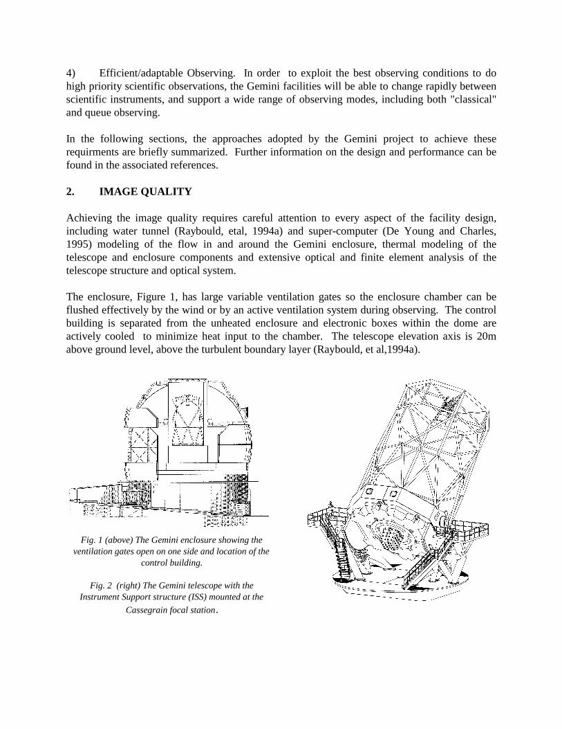
The primary mirror assembly is illustrated in Figure 3. The image quality requirements have ledto a new approach to the support and alignment of the primary mirror (Stepp and Huang, 1994).It is supported by 120 axial supports with both passive and active components together with auniform air pressure support. Lateral support is provided by 72 passive hydraulic supportsarranged around the circumference of the mirror.
Fig. 3 An overview of the primary mirror assembly indicating major components.
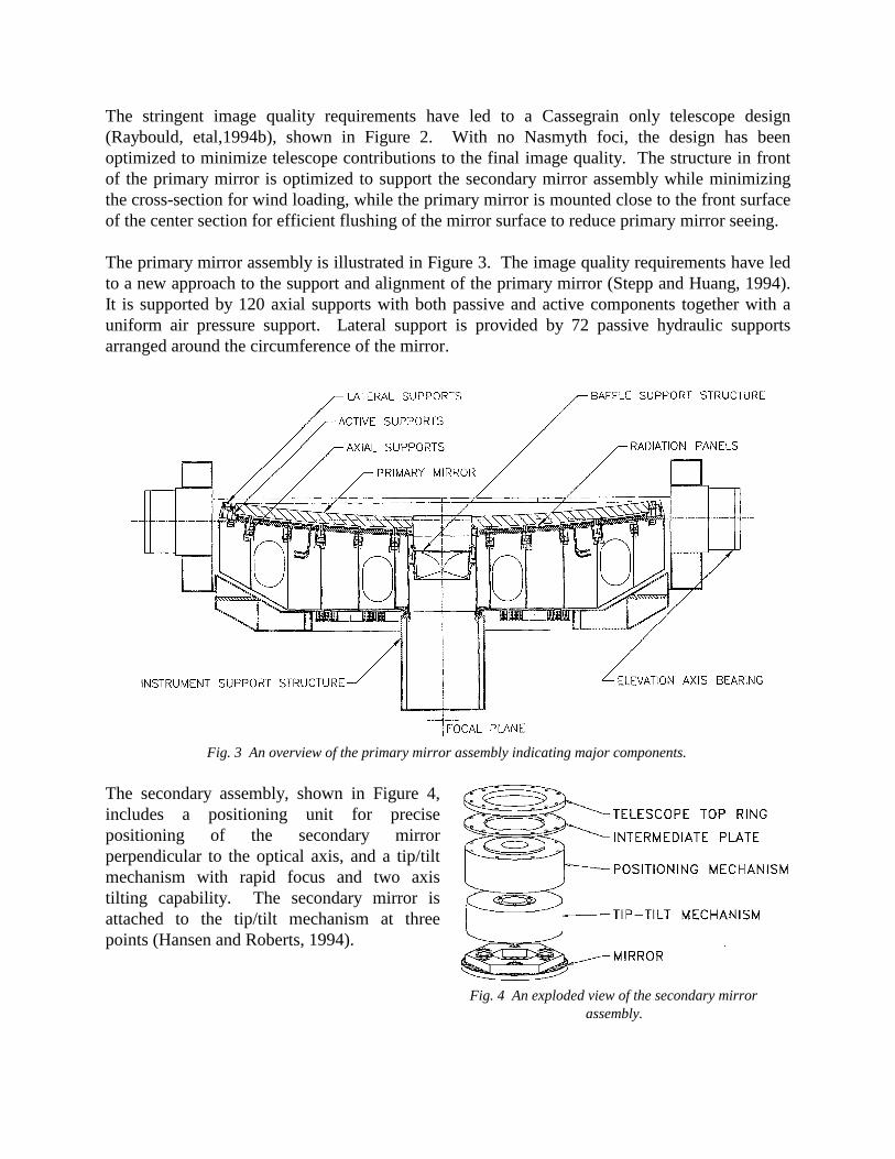
The secondary assembly, shown in Figure 4,includes a positioning unit for precisepositioning of the secondary mirrorperpendicular to the optical axis, and a tip/tiltmechanism with rapid focus and two axistilting capability. The secondary mirror isattached to the tip/tilt mechanism at threepoints (Hansen and Roberts, 1994).
Fig. 4 An exploded view of the secondary mirrorassembly.
Thermal control
The intrinsic image quality of a telescope is easily degraded by turbulent mixing of air atdifferent temperatures resulting from temperature differentials between the ambient air andcomponents of the telescope and enclosure (see e.g. Racine, etal, 1991). The design of theGemini telescope and enclosure has been substantially driven by the requirement to minimizethese effects.
During the day, the enclosure skin is actively ventilated to reduce the solar heat load on theinternal enclosure volume, allowing the internal enclosure structure and telescope structure to bepreconditioned to near the nightime ambient air temperature by daytime air-conditioning of theenclosure volume. In addition, the external surfaces of the dome and upward looking telescopesurfaces are painted with a low emissivity paint to mimimize supercooling below ambienttemperature during the nighttime hours.
The primary mirror assembly incorporates a radiation plate between the primary mirror andmirror cell for daytime preconditioning of the bulk mirror temperature at or below that expectedat the start of observing and slow control of the mirror temperature during the night. In addition,in order to track the nighttime temperature variations with higher fidelity, a coating heatingcapability is under development. An electrical current is conducted through the reflective coatingon the primary mirror, controlling the surface temperature by ohmic heating (Greenhalgh, Stepp,Hansen, 1994). The current flow is adjusted to follow variations in ambient temperature.Simulations and prototype testing show that the a 1 deg C temperature change can be achieved inabout 15 min.
Active figure and alignment control
A pair of peripheral wavefront sensors (PWFS’s), consisting of 8x8 Shack-Hartmann WFScoupled to CCD detectors, analyse the incoming wavefront, using reference stars in the field ofview surrounding the science field, to continuously correct the primary mirror figure and thealignment of the primary and secondary relative to the science focal plane on time scales of a fewminutes while observing. The PWFS’s patrol a 14 arcmin cassegrain guide field, providingvirtually 100% sky coverage for this function.
Tip/tilt and fast focus correction
Image motion due to atmospheric wavefront tilt and windshake of the telescope/enclosuretogether with focus changes due to atmosphere and telescope effects, are sensed by low-orderWFS’s integrated into each instrument. The tip/tilt and focus errors sensed by these On-Instrument WFS’s (OIWFS) are corrected by means of small tilts and piston motions of thearticulated secondary mirror. The OIWFS’s observe reference stars within the isoplanatic patcharound the science FOV by means of pickoff mirrors or dichroic beam splitters. The Gemini IRinstruments are being designed with OIWFS's that are sensitive at near-IR wavelengths (1-2.5
m) in order to achieve best imaging performance in dark clouds (Simons, 1995), potentiallybetter image motion correction even at the galactic poles, and to enable daytime observing .
3. VERSATILE OPTICAL/IR CAPABILITIES
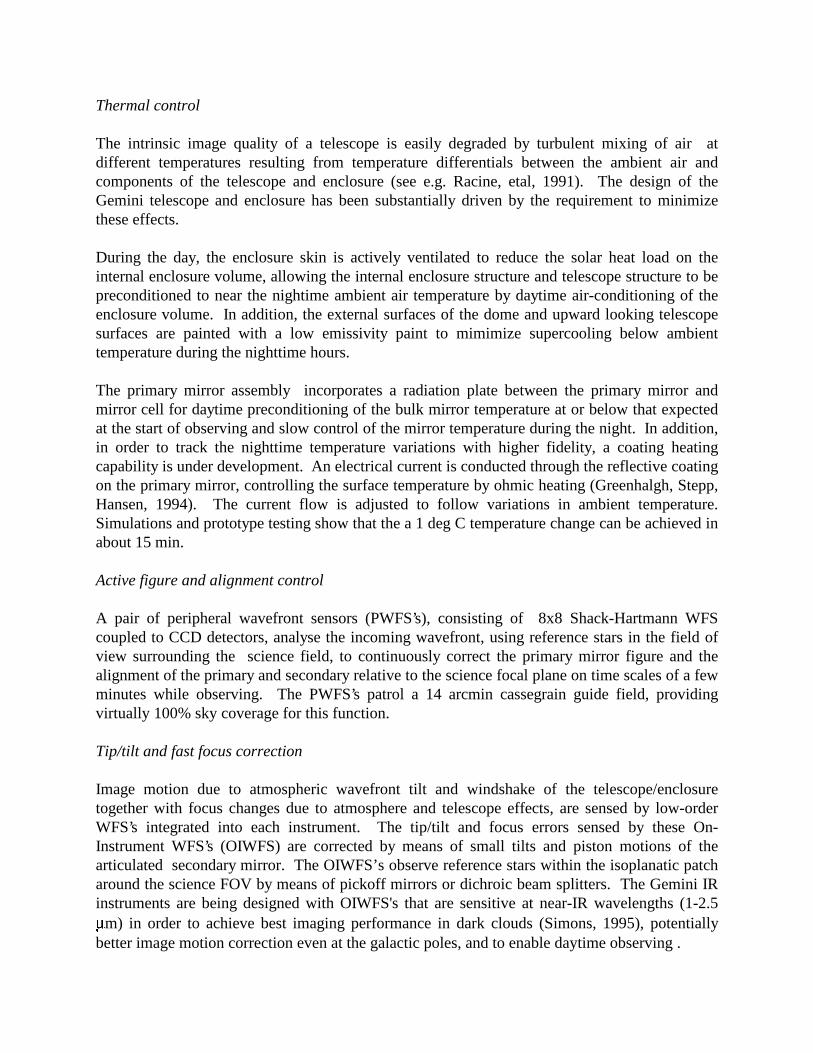
Broad wavelength coverage is a major feature of the Gemini telescopes. In order to achieve thethroughput requirements and goals for the primary and secondary mirror the coating plants willneed the capability for depositing a variety of mirror coatings. Gemini has undertakendevlopment programs for sputtered Alumimum coatings and for protected Ag coatings. Thereflectivity of samples produced by these programs is shown in Table I.
Table I : Al and Ag Sample Reflectivity
0.33-0.40 m
0.40-0.70 m
0.70-1.1 m
Bare Al 0.87 0.89 0.90Bare Ag 0.80 0.97 0.98Minimal Protected Ag 0.76 0.95 0.98Protected Ag 0.86 0.92 0.96Meets Requirements
Meets Goals
Both Mauna Kea and Cerro Pachon are very dry sites, except for the Southern Hemispheresummer months, with transmission in portions of the atmospheric windows around 2.3, 3.7 and10 m in excess of 98%. In order to exploit the corresponding very low atmospheric backgroundemission, the Gemini telescopes will have an IR configuration with telescope emissivity less than4% and a goal of 2% in the thermal IR beyond 2.27 m. The IR configuration includes thincrosssection secondary vanes, a pupil stop at the secondary mirror, and minimum bevels on thesecondary mirror. The secondary mirror itself has been designed with a central hole so even inreflection the focal plane "sees" only cold sky in the vicinity of the central primary mirror boreand chimney baffle. Emissivity measurements on bare and protected Ag coatings together withAPART analysis of the telescope configuration indicates that with Ag coatings on the primaryand secondary mirrors, the Gemini telescope emissivity should approach the goal of 2%.(Dinger,1993)
In order to maintain the extremely low telescope emissivity for extended periods of time betweenmirror recoatings, an effective and frequent (about 1/week) in-situ mirror cleaning capability isrequired. Comparative cleaning tests using CO2 snow and Excimer lasers indicate potentiallybetter cleaning performance for laser cleaning (Kimura, Kim, and Balick, 1994). Furthercleaning tests on sample Aluminum and bare and protected Ag mirrors are underway.
The articulated secondary mirror will be capable of both two axis tilting for image motioncompensation and "chopping" at 5 or 10 hz for 10 and 20 m observations. Both capabilities areincorporated into the tip/tilt mechanism supporting the secondary mirror.
The telescopes are equipped with a fixed chimney baffle mounted from the central hole in theprimary mirror, and a three - position remotely deployable secondary baffle mounted on the
positioning unit behind the secondary mirror. The optical configuration uses the fully deployedsecondary baffle position, about 2 m diameter, to block direct sky illumination of a 12 arcminfield in the telescope focal plane. The IR configuration provides a fully retracted postion for thesecondary baffle and an intermediate position with deployed diameter of between 1.1 and 1.2 mdiameter.
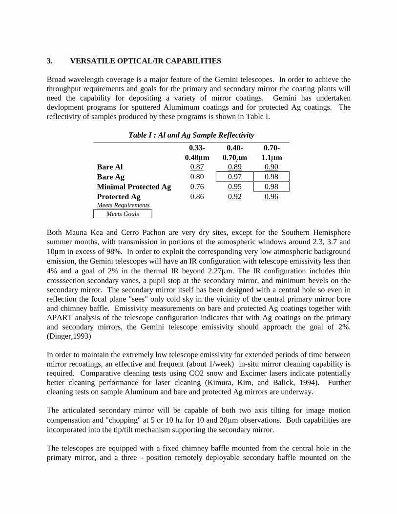
The Cassegrain Instrument Support Structure (ISS) (Figure 5) incorporates acquisiton andguiding capabilities, the PWFS’s, and a science fold mirror for directing the telescope beam toany of the four side-looking insturment ports. The science fold mirror can also be retracted toallow telescope beam access to the uplooking instrument port. The ISS provides for three 2000kgm science instruments mounted simultaneously, in addition to a Calibration Unit and anAdaptive Optics (AO) unit on opposite sidelooking ports. The AO module is accessed by a AOfeed mirror in the ISS. The entire cassegrain assembly rotates to maintain the orientation ofscientific instruments with respect to the sky during an observation (Montgomery, Robertson andWieland, 1994).
Fig. 5 The Instrument Support Structure(ISS) layout. Instruments can be mounted on the side-looking faces and onthe up-looking face of the ISS.
4. EFFICIENT/ADAPTABLE OBSERVING
The observatory operating modes will be key to achieving maximum scientific productivity ofthe Gemini telescopes. Observing time will be at a premium on the Gemini telescopes, and everyeffort will be taken to obtain observations in a highly efficient manner that exploits the uniquecharacteristics of the telescopes and sites. The facilities will support "classical" observingmodes with the astronomer present at the telescope, but also a wide range of modes with theastronomer either participating remotely, or more innovative modes (for ground basedtelescopes) including queue scheduled observing where observatory staff carry out observationsfor the astronomer when the observing conditions are most apporpriate for those observations.At least 50% of the observing time will be allocated to queue scheduled observations in order to
exploit the best conditions scientifically. In addition, to achieve maximum scientific productivityunder changing sky conditions, the observer can readily change between mounted instrumentsduring the night by reconfiguration of the control system and secondary baffle and redirecting thescience beam with the science fold mirror. Efficient observation preparation tools, schedulingand rescheduling tools, environmental monitoring and data quality assessment capabilities willbe provided. In addition, the necessary communications to support remote observing will beavailable. Gemini will keep a permanent record of observations and ancillary data in perpetuity,sufficient for the future re-creation of the observations and adequate for useful archiving.
The time allocation process relies on National Project Offices within the partner countries tointerface with their communities. Proposals will be solicited semi-annually from the partnercommunities by the Gemini National Project offices. Within each of the partner countries anappropriate National TAC will rank the proposals into priority-ordered lists for "classical" andqueue observations and forward them to Gemini, who will merge the national lists into apreliminary schedule of "classical" time and queue listings, taking into account observationrequirements, national shares, instrument availability and engineering support requirements. Asingle International TAC, made up of representatives from the NTAC’s, will review thepreliminary schedules and make recommendations for the final schedules. The ITAC will alsoreview the results of past observing periods to ensure fairness and effectiveness of the allocationand observation execution processes.
5. INSTRUMENTATION PROGRAM
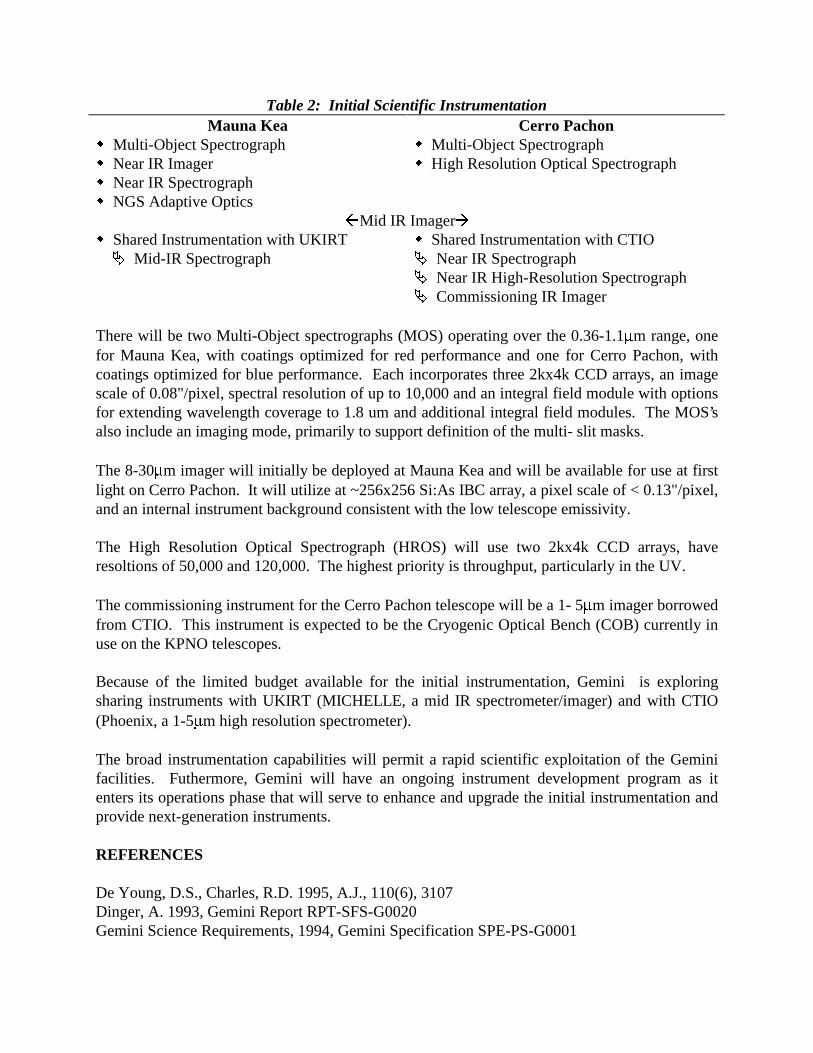
All of the effort going into the telescope and facility design naturally leads to tight performancespecification for the facility instrumentation. Instruments can be mounted on three faces of theISS. Table 2 lists the instruments that will make up the initial complement at each site (Simons,Robertson and Mountain, 1995).
A Natural Guide Star (NGS) Adaptive Optics system will be constructed for the Mauna Keatelescope, designed for use in the 0.9 to 2.5 m range and capable of delivering images withStrehl ratios of 0.5 at 1.6 m in median seeing conditions. The corrected beam can be fed to anyinstrument port on the ISS.
The 1-5 m imager will be used for commissioning the Mauna Kea telescope, as well as scientificobservations, and will utilize a 10242 InSb array, have plate scales of 0.02,0.05 and 0.11"/pixelfor use with and without AO, and very low internal instrument background, consistent with thelow telescope emissivity.
The 1-5 m spectrograph for Mauna Kea is also based on use of a 10242 InSb array, will providespectral resolutions of about 2000 and 8000, two plate scales (0.05"/pixel and 0.15"/pixel), crossdispersion capability, and option for an integral field module.
Multi-Object Spectrograph Multi-Object Spectrograph Near IR Imager High Resolution Optical Spectrograph Near IR Spectrograph NGS Adaptive Optics
Mid IR Imager Shared Instrumentation with UKIRT Shared Instrumentation with CTIO
Mid-IR Spectrograph Near IR Spectrograph Near IR High-Resolution Spectrograph Commissioning IR Imager
There will be two Multi-Object spectrographs (MOS) operating over the 0.36-1.1 m range, onefor Mauna Kea, with coatings optimized for red performance and one for Cerro Pachon, withcoatings optimized for blue performance. Each incorporates three 2kx4k CCD arrays, an imagescale of 0.08"/pixel, spectral resolution of up to 10,000 and an integral field module with optionsfor extending wavelength coverage to 1.8 um and additional integral field modules. The MOS’salso include an imaging mode, primarily to support definition of the multi- slit masks.
The 8-30 m imager will initially be deployed at Mauna Kea and will be available for use at firstlight on Cerro Pachon. It will utilize at ~256x256 Si:As IBC array, a pixel scale of < 0.13"/pixel,and an internal instrument background consistent with the low telescope emissivity.
The High Resolution Optical Spectrograph (HROS) will use two 2kx4k CCD arrays, haveresoltions of 50,000 and 120,000. The highest priority is throughput, particularly in the UV.
The commissioning instrument for the Cerro Pachon telescope will be a 1- 5 m imager borrowedfrom CTIO. This instrument is expected to be the Cryogenic Optical Bench (COB) currently inuse on the KPNO telescopes.
Because of the limited budget available for the initial instrumentation, Gemini is exploringsharing instruments with UKIRT (MICHELLE, a mid IR spectrometer/imager) and with CTIO(Phoenix, a 1-5 m high resolution spectrometer).
The broad instrumentation capabilities will permit a rapid scientific exploitation of the Geminifacilities. Futhermore, Gemini will have an ongoing instrument development program as itenters its operations phase that will serve to enhance and upgrade the initial instrumentation andprovide next-generation instruments.
REFERENCES
De Young, D.S., Charles, R.D. 1995, A.J., 110(6), 3107Dinger, A. 1993, Gemini Report RPT-SFS-G0020Gemini Science Requirements, 1994, Gemini Specification SPE-PS-G0001