24
The Internet Internet Technologies and Applications
| Date post: | 26-Dec-2015 |
| Category: |
Documents |
| Upload: | collin-gordon |
| View: | 217 times |
| Download: | 1 times |

The Internet
Internet Technologies and Applications

ITS 413 - The Internet 2
Aim and Contents
• Aim:– Review the main concepts and technologies used in the Internet
– Describe the real structure of the Internet today
• Contents:– Internetworking and internets
– Internet Protocol (IP)
– The Internet

ITS 413 - The Internet 3
Internetworking
• Each access/core network may use different network technologies– Depending on the requirements of users and operators
• We want any user to be able to communicate with any other user, independent of network technology
– Use a common network protocol (IP) and routers to connect the networks
Core Network(or Backbone/Transport Network)
CoreNetwork
CoreNetwork Core
Network
CoreNetwork
AccessNetwork
AccessNetwork
AccessNetwork
AccessNetwork
AccessNetwork
AccessNetwork
AccessNetwork
AccessNetwork

ITS 413 - The Internet 4
Internet Protocol
• Features of IP– Connection-less, network layer, datagram packet switching system
– IP datagrams: delivery from source to destination• No guarantees! (datagrams may be lost, arrive out-of-order, arrive in error)
– Multiplexing• Protocol numbers are used to identify the type of data (e.g. TCP or UDP)
– IP addressing
– Fragmentation and Re-assembly
• IP is designed to support many different types of transport protocols, and operate over many different types of data link protocols

5
IP in Internet 5 Layer Model
IPARP
ICMP
TCP UDP
HT
TP
SM
TP
PO
P3
IMA
P4
DN
S
SN
MP
Many other application protocols
AT
M
IEE
E 8
02 (
Eth
erne
t, W
irele
ss L
AN
, …)
X.2
5
Fra
me
Rel
ay
PD
H a
nd S
DH
Oth
er L
AN
/WA
Nte
chno
logi
es
App
licat
ion
Tra
nspo
rtN
etw
ork
Dat
a Li
nkP
hysi
cal
Oth
ers
Routing protocols

ITS 413 - The Internet 6
IP Hosts and Routers
• Hosts are the end-devices (stations)– Assume hosts have single interface (only attached to one LAN/WAN)
• In practice, hosts can have multiple interfaces
– Hosts do not forward datagrams• A host is either source or destination; if a host receives a datagram and the host is not
the destination, then the host will discard the datagram
• Routers are the datagram packet switches– Routers have two or more interfaces (since they connect LANs/WANs together)– Routers forward datagrams– Routers can act as a source or destination of datagrams (however this is mainly
for management purposes)
• IP routing is the process of discovering the best path between source and destination
– Adaptive routing protocols execute on routers/hosts to find the path; the paths are stored in routing tables on routers and hosts
• IP forwarding is the process of delivering an IP datagram from source to destination

ITS 413 - The Internet 7
IP Hosts and Routers
• IP is implemented at Layer 3 (Networking layer) in Hosts and Routers– Typically as software in a host or router operating system
• There may be 0 or more Routers between a source Host and destination Host
Subnet B Subnet ZMultiple subnets
and routersSubnet A
IP
Transport Protocols
Application Protocols
DLL A
PHY A
IP
Transport Protocols
Application Protocols
DLL Z
PHY Z
IP
DLL A
PHY A
DLL B
PHY B
IP
DLL Y
PHY Y
DLL Z
PHY Z
IP
DLL B
PHY B
DLL C
PHY C
Source Host Destination HostRouter 1 Router 2 Router N
Subnet A Subnet B Subnet Z

ITS 413 - The Internet 8
IP Datagram
• IP datagram consists of a variable length header and variable length of data– Header has 20 bytes for required fields; then optional fields bringing maximum
size to 60 bytes– Data length is variable (but must be integer multiple of 8 bits in length); maximum
size of datagram (that is, header + data) is 65,535 bytes
Time To Live Header Checksum
Source Address
Destination Address
Options + Padding
Protocol
Flags Fragment OffsetIdentification
Total LengthVersionHeader Length
DiffServ ECN
Data
0 3116
20 b
ytes

ITS 413 - The Internet 9
IP Datagram Fields• Version [4 bits]: version number of IP;
current value is 4 (IPv4)• Header Length [4 bits]: length of header,
measured in 4 byte words; minimum value is 5 (20 bytes); maximum is 15 (60 bytes)
• DiffServ [6 bits]: Used for quality of service control. DiffServ and ECN used to be called Type of Service field.
• ECN [2 bits]: Used for notifying nodes about congestion
• Total Length [16 bits]: total length of the datagram, including header, measured in bytes. Max 65535 bytes in datagram
• Identification: sequence number for datagram
• Flags: 2 bits are used for Fragmentation and Re-assembly, the third bit is not used
– Don’t Fragment bit: if set to 1, then the datagram will not be fragmented (it will be discarded if fragmentation is needed)
– More Fragments bit: if datagram is fragmented, then set to 1 on all fragments except the last fragment
• Fragment Offset [13 bits]: Indicates where this fragment belongs in the original datagram, measured in blocks of 8 bytes
• Time To Live [8 bits]: how long datagram should remain in internet. In practice used as a hop counter (a router decrements every time it is forwarded)
• Protocol [8 bits]: indicates the next higher layer protocol with a code (e.g. TCP = 6; UDP = 17; ICMP = 1)
• Header Checksum [16 bits]: error-detecting code applied to header only (to check for errors in the header); recomputed at each router
• Source Address [32 bits]: IP address of source host
• Destination Address [32 bits]: IP address of destination host
• Options: variable length fields to include options
• Padding: used to ensure datagram is multiple of 4 bytes in length
• Data: variable length of the data

ITS 413 - The Internet 10
IP Addressing (Classless)
• 32 bit IP address is divided into two parts:– Network portion: identifies the IP network (or subnet) within an internet– Host portion: identifies a host within the IP network
• An address mask or subnet mask identifies where the split is:– The mask is 32 bits: a bit 1 indicates the corresponding bit in the IP
address is the network portion; a bit 0 indicates the corresponding bit in the IP address is the host portion
– The mask can be given in dotted decimal form or a shortened form, which counts the number of 1 bits
• The above example can be written as /22, and the IP address as 130.17.41.129/22
IP address, 130.17.41.129: 10000010 00010001 00101001 10000001Subnet mask, 255.255.252.0: 11111111 11111111 11111100 00000000
Network, 130.17.40.0: 10000010 00010001 00101000 00000000
Network portion Host portion
ITS 413 - The Internet 11
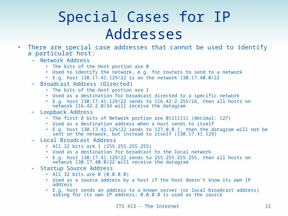
Special Cases for IP Addresses• There are special case addresses that cannot be used to identify a particular host:
– Network Address• The bits of the Host portion are 0• Used to identify the network, e.g. for routers to send to a network• E.g. host 130.17.41.129/22 is on the network 130.17.40.0/22
– Broadcast Address (Directed)• The bits of the Host portion are 1• Used as a destination for broadcast directed to a specific network• E.g. host 130.17.41.129/22 sends to 116.42.2.255/24, then all hosts on network 116.42.2.0/24 will
receive the datagram– Loopback Address
• The first 8 bits of Network portion are 01111111 (decimal: 127)• Used as a destination address when a host sends to itself• E.g. host 130.17.41.129/22 sends to 127.0.0.1, then the datagram will not be sent on the network, but
instead to itself (130.17.41.129)– Local Broadcast Address
• All 32 bits are 1 (255.255.255.255)• Used as a destination for broadcast to the local network• E.g. host 130.17.41.129/22 sends to 255.255.255.255, then all hosts on network 130.17.40.0/22 will
receive the datagram– Startup Source Address
• All 32 bits are 0 (0.0.0.0)• Used as a source address by a host if the host doesn’t know its own IP address• E.g. host sends an address to a known server (or local broadcast address) asking for its own IP
address; 0.0.0.0 is used as the source

ITS 413 - The Internet 12
IP Routing
• IP does not include a routing protocol; any routing protocol may be used in an IP network
• Example: Link State Routing– Each router records the state of its own links: who do they link to and
what does the link cost?
– Each router sends a Link State Packet to all other routers in the network (using flooding)
• Repeated when the link state changes
– For all Link State Packets received, each router finds the least cost path from itself to every other node
• Dijkstra’s algorithm
– Each router builds its routing table• Routing table: “in order to reach destination X, send to next node Y”
• IP uses the routing table to determine where to forward IP datagrams

The Internet Structure Today
ITS 413 - The Internet 14
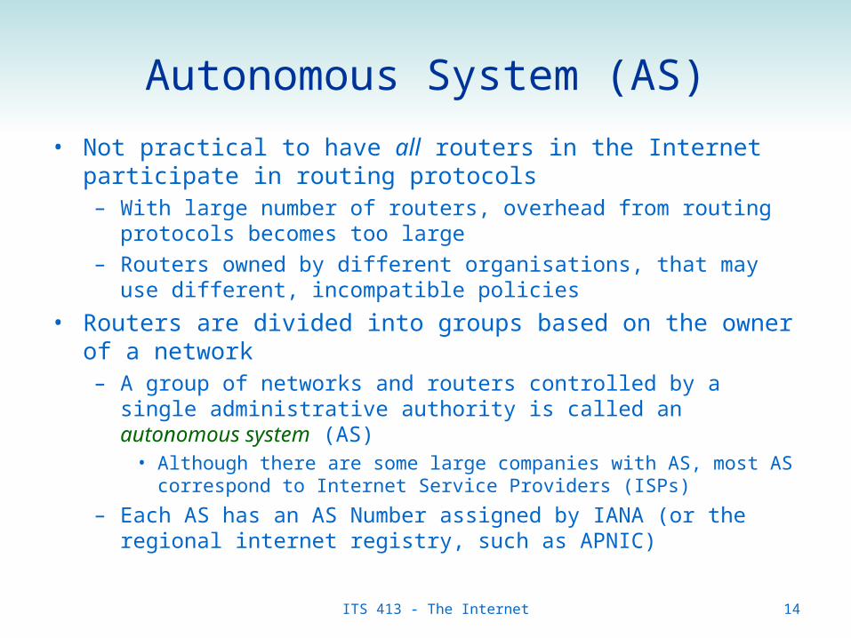
Autonomous System (AS)
• Not practical to have all routers in the Internet participate in routing protocols– With large number of routers, overhead from routing protocols becomes
too large
– Routers owned by different organisations, that may use different, incompatible policies
• Routers are divided into groups based on the owner of a network– A group of networks and routers controlled by a single administrative
authority is called an autonomous system (AS)• Although there are some large companies with AS, most AS correspond to
Internet Service Providers (ISPs)
– Each AS has an AS Number assigned by IANA (or the regional internet registry, such as APNIC)

15
AS Examples
• AS4637: Reach• AS38040: TOT Internet Gateway• AS2516: KDDI (Japan)
Allocated addresses in Thailand, 1 Oct 2008Source: http://internet.nectec.or.th/ Thailand Internet Map, 13 Oct 2008
Source: http://internet.nectec.or.th/

ITS 413 - The Internet 16
Routing with Autonomous Systems
• Routing within an AS is performed using an Interior Gateway Protocol (IGP)– Gateway means the same as Router in this context
– There are different IGPs available and in use; the owner of the AS may choose depending on their requirements
• RIP, OSPF, IS-IS, IGRP, EIGRP, …
• Routing between AS’s is performed using an Exterior Gateway Protocol (EGP)– There is only one EGP used in the Internet: Border Gateway Protocol
(BGP)
– Neighbour AS’s use BGP to advertise which networks are reachable via each other

ITS 413 - The Internet 17
Routers and Autonomous Systems
AS1
AS5
AS3
AS2
AS4
AS5
AS5NetA
NetB
NetCNetF
NetD
NetH
NetGNetE
Autonomous System 3 may contain multiple IP networks (core or access)
connected by Interior Routers
The Internet is made up by a collection of Autonomous Systems connected by Exterior (or Border) Routers

ITS 413 - The Internet 18
Connecting Between Autonomous Systems
• Two autonomous systems that connect together are known as peers– Usually (but not necessarily) an AS represents an ISP
• Connection between peers requires:– Physical Connection
• Private peering– Two peers connect their border routers with a point-to-point connection such as
SDH
• Public peering– Multiple peers connect via shared network (e.g. Ethernet), usually at the one
location called Internet Exchange Point (IXP or IX)
– Agreement• Often a commercial contract is established, and technical/commercial/social
policies agreed upon• Different types of agreements:
– Transit: ISP1 pays ISP2 for traffic of ISP1 to access Internet via ISP2 (ISP2 is usually much larger than ISP1)
– Peering: ISP1 and ISP2 exchange each others traffic freely

ITS 413 - The Internet 19
ISPs, Transit, Peering and Tiers
• Tier 1 ISPs do not have to pay for transit for any destination on the Internet– All Tier 1 ISPs peer with each other– Currently about 15 Tier 1 ISPs in the world, including:
• AT&T, Qwest, NTT/Verio, Verizon, GlobalCrossing, …
• Tier 2 ISPs are large ISPs that must pay for transit from some Tier 1 ISPs– Tier 2 ISPs often peer with other ISPs– Usually large regional or national ISPs
• Tier 3 ISPs usually pay for transit from Tier 2 (or 1) ISPs• Customers (such as SIIT or you) pay for transit from one of the ISPs
• (Note the definition of tiers and peering differs across some sources; but the main concept of a hierarchy between ISPs, plus direct peering, applies)

ITS 413 - The Internet 20
Example of Transit and Peers
AS4
AS1 AS2 AS3Peer Peer
Peer
AS5
AS8
AS7AS4
AS9
AS10
AS11
AS12
AS13
AS14
AS15
AS6
NetA NetB NetC NetD NetE NetF NetG NetH NetI NetJ NetK NetL
Tier 1
Tier 2
Tier 3
Up
stre
am
Do
wn
stre
am
All links to a higher level AS (or ISP) are transit links: the customer pays for the traffic to transit the upstream ISPs network. All Tier 1 ISPs (AS) must peer with every other Tier 1 ISP

ITS 413 - The Internet 21
Example of Transit and Peers
Here three ISPs have reached agreement so that traffic between their networks is exchanged for free, that is, peering agreements.
AS4
AS1 AS2 AS3Peer Peer
Peer
AS5
AS8
AS7AS4
AS9
AS10
AS11
AS12
AS13
AS14
AS15
PeerAS6 Peer
NetA NetB NetC NetD NetE NetF NetG NetH NetI NetJ NetK NetL
Tier 1
Tier 2
Tier 3
Ups
trea
m
Dow
nstr
eam
Peer

ITS 413 - The Internet 22
Internet Exchange Points
• Internet Exchange Points allow many ISPs to peer with each other– ISPs have connections into IXPs, and the IXP runs a switched network
(often Ethernet) to connect all ISPs
– IXPs are often large buildings or data centres; large IXPs support 100’s of ISPs
AS4 AS6
AS5
Internet Exchange Point
100/1000 Mb/s Ethernet

ITS 413 - The Internet 23
Content Providers
• Content Providers are a special case of network in the Internet– Example: Google/Youtube, Microsoft, Sony, Yahoo, …
– Most traffic is outbound/upstream (going from Content Provider to ISP and then to customer)
• Connect to Tier 1/2 ISPs: pay for transit• Also creating peering arrangements
– Example: Google have peering arrangements with multiple Tier2/3 ISPs• Google traffic (such as Youtube videos) sent over the peer ISPs network is
free– Google does not have to pay a higher tier (such as Tier 1) for transit
– Customers of the ISP get faster access to Google content
• Peering arrangements between ISPs and Content Providers benefits:– Lower transit costs for Content Providers
– Better service from ISPs; more customers

ITS 413 - The Internet 24
Summary
• IP is used for internetworking the many different access/core networks together– Idea: Allow any IP device to communicate with any other IP device in an
internet
• The Internet today has some hierarchical structure– Autonomous Systems (AS) typically correspond to Internet Service
Providers (ISPs)• Within an AS, routing is performed using one of many interior gateway
protocols• Between AS’s, routing is performed using Border Gateway Protocol (BGP)
– End-users (individuals, businesses) pay for transit via ISPs
– ISPs pay for transit via other ISPs, and/or peer with ISPs


![Using Future Internet Technologies to Strengthen Criminal ...€¦ · Internet of Things [IoT]) of Web 4.0. Web 3.0 and 4.0 technologies will have a variety of poten-tial applications](https://static.documents.pub/doc/80x56/5b031c2d7f8b9a89208bb033/using-future-internet-technologies-to-strengthen-criminal-internet-of-things.jpg)


