291 THE LHC VACUUM SYSTEM Oswald Gröbner, for the LHC Vacuum Group CERN, Geneva, Switzerland Abstract The Large Hadron Collider (LHC) project, now in the advanced construction phase at CERN, comprises two proton storage rings with colliding beams of 7-TeV energy. The machine is housed in the existing LEP tunnel with a circumference of 26.7 km and requires a bending magnetic field of 8.4 T with 14-m long superconducting magnets. The beam vacuum chambers comprise the inner ‘cold bore’ walls of the magnets. These magnets operate at 1.9 K, and thus serve as very good cryo-pumps. In order to reduce the cryogenic power consumption, both the heat load from synchrotron radiation emitted by the proton beams and the resistive power dissipation by the beam image currents have to be absorbed on a ‘beam screen’, which operates between 5 and 20 K and is inserted inside the vacuum chamber. The design of this beam screen represents a technological challenge in view of the numerous and often conflicting requirements and the very tight mechanical tolerances imposed. The synchrotron radiation produces strong outgassing from the walls. The design pressure necessary for operation must provide a beam lifetime of several days. An additional stringent requirement comes from the power deposition in the superconducting magnet coils due to protons scattered on the residual gas, which could lead to a magnet, quench and interrupt the machine operation. Cryopumping of gas on the cold surfaces provides the necessary low gas densities but it must be ensured that the vapour pressure of cryosorbed molecules, of which H 2 and He are the most critical species, remains within acceptable limits. In the warm straight sections of the LHC the pumping speed requirement is determined by ion-induced desorption and the resulting vacuum stability criterion. 1. INTRODUCTION The Large Hadron Collider (LHC) [1] consists of a pair of superconducting storage rings with a circumference of 26.7 km. Two proton beams, of 530 mA and an energy of 7.0 TeV, circulate in opposite directions. Of the 54-km total length, the arcs account for almost 48 km and will be at 1.9 K, the temperature of the superconducting magnets. The basic layout of LHC follows the existing LEP machine, with eight long straight sections and eight bending arcs. The present experimental programme includes two high-luminosity experiments (ATLAS and CMS) as well as a heavy ion experiment (ALICE) and a B-physics experiment shown schematically in Fig.1. In this figure is also shown the position for the two beam transfer lines from the existing SPS accelerator, which will be used as the injector, the locations for the accelerating RF system, the beam dump system and the two beam cleaning insertions. To fit the 7-TeV rings into the existing LEP tunnel special design concepts are needed for the machine components and, most specifically, superconducting magnets with 8.3 T field. The magnetic bending field of 8.3 T implies that the superconducting magnets which use commercially available NbTi superconductors must operate at a temperature well below 4.2 K. A very attractive technical solution for the LHC has been to immerse the magnets in a bath of superfluid helium at 1.9 K. A selection of the most significant machine parameters is given in Table 1.
Transcript
291
THE LHC VACUUM SYSTEM
Oswald Gröbner, for the LHC Vacuum GroupCERN, Geneva, Switzerland
AbstractThe Large Hadron Colli der (LHC) project, now in the advancedconstruction phase at CERN, comprises two proton storage rings withcolli ding beams of 7-TeV energy. The machine is housed in the existingLEP tunnel with a circumference of 26.7 km and requires a bendingmagnetic field of 8.4 T with 14-m long superconducting magnets. The beamvacuum chambers comprise the inner ‘cold bore’ walls of the magnets.These magnets operate at 1.9 K, and thus serve as very good cryo-pumps. Inorder to reduce the cryogenic power consumption, both the heat load fromsynchrotron radiation emitted by the proton beams and the resistive powerdissipation by the beam image currents have to be absorbed on a ‘beamscreen’ , which operates between 5 and 20 K and is inserted inside thevacuum chamber. The design of this beam screen represents a technologicalchallenge in view of the numerous and often confli cting requirements andthe very tight mechanical tolerances imposed. The synchrotron radiationproduces strong outgassing from the walls. The design pressure necessaryfor operation must provide a beam lifetime of several days. An additionalstringent requirement comes from the power deposition in thesuperconducting magnet coils due to protons scattered on the residual gas,which could lead to a magnet, quench and interrupt the machine operation.Cryopumping of gas on the cold surfaces provides the necessary low gasdensities but it must be ensured that the vapour pressure of cryosorbedmolecules, of which H2 and He are the most criti cal species, remains withinacceptable limits. In the warm straight sections of the LHC the pumpingspeed requirement is determined by ion-induced desorption and theresulting vacuum stabilit y criterion.
1. INTRODUCTION
The Large Hadron Colli der (LHC) [1] consists of a pair of superconducting storage rings with acircumference of 26.7 km. Two proton beams, of 530 mA and an energy of 7.0 TeV, circulate inopposite directions. Of the 54-km total length, the arcs account for almost 48 km and will be at 1.9 K,the temperature of the superconducting magnets. The basic layout of LHC follows the existing LEPmachine, with eight long straight sections and eight bending arcs. The present experimentalprogramme includes two high-luminosity experiments (ATLAS and CMS) as well as a heavy ionexperiment (ALICE) and a B-physics experiment shown schematically in Fig.1. In this figure is alsoshown the position for the two beam transfer lines from the existing SPS accelerator, which will beused as the injector, the locations for the accelerating RF system, the beam dump system and the twobeam cleaning insertions.
To fit the 7-TeV rings into the existing LEP tunnel special design concepts are needed for themachine components and, most specifically, superconducting magnets with 8.3 T field. The magneticbending field of 8.3 T implies that the superconducting magnets which use commercially availableNbTi superconductors must operate at a temperature well below 4.2 K. A very attractive technicalsolution for the LHC has been to immerse the magnets in a bath of superfluid helium at 1.9 K. Aselection of the most significant machine parameters is given in Table 1.
292
Fig. 1 General layout of LHC
Table 1Principal machine parameters for proton-proton colli sions
Value Unit
Energy 7 TeV
Dipole field 8.33 T
Coil aperture 56 mm
Luminosity 1034 s-1 cm-2
Injection energy 450 GeV
Circulating current /beam 0.56 A
Bunch spacing 25 ns
Particles/bunch 1.1 1011
Stored beam energy 350 MJ
Normalised transverse emittance 3.75 µm
R.m.s. bunch length 0.075 m
Beam lifetime 22 h
Luminosity li fetime 10 h
Energy loss/turn 6.7 keV
Criti cal photon energy 45 eV
Linear photon flux 1 1017 m-1 s-1
Total radiated power/beam 3.8 kW
293
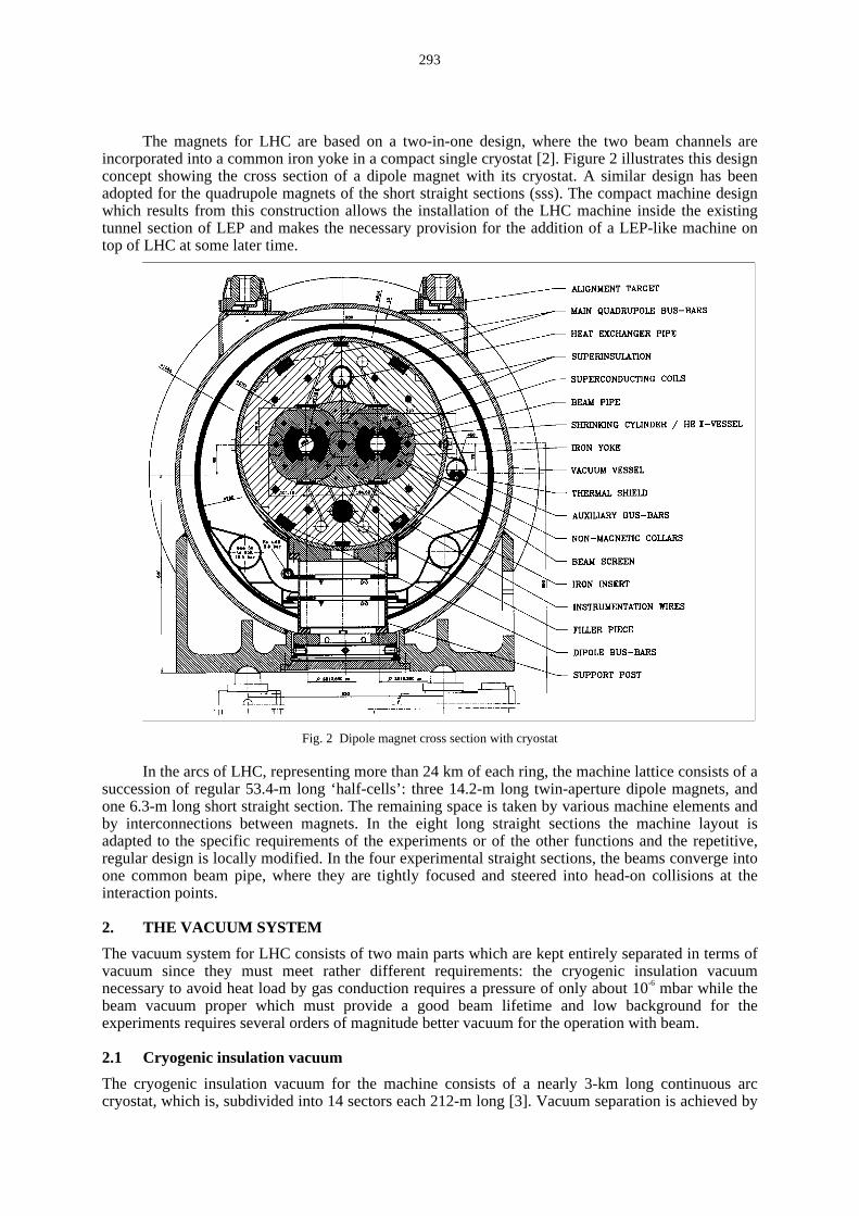
The magnets for LHC are based on a two-in-one design, where the two beam channels areincorporated into a common iron yoke in a compact single cryostat [2]. Figure 2 ill ustrates this designconcept showing the cross section of a dipole magnet with its cryostat. A similar design has beenadopted for the quadrupole magnets of the short straight sections (sss). The compact machine designwhich results from this construction allows the installation of the LHC machine inside the existingtunnel section of LEP and makes the necessary provision for the addition of a LEP-like machine ontop of LHC at some later time.
Fig. 2 Dipole magnet cross section with cryostat
In the arcs of LHC, representing more than 24 km of each ring, the machine lattice consists of asuccession of regular 53.4-m long ‘half-cells’ : three 14.2-m long twin-aperture dipole magnets, andone 6.3-m long short straight section. The remaining space is taken by various machine elements andby interconnections between magnets. In the eight long straight sections the machine layout isadapted to the specific requirements of the experiments or of the other functions and the repetiti ve,regular design is locally modified. In the four experimental straight sections, the beams converge intoone common beam pipe, where they are tightly focused and steered into head-on colli sions at theinteraction points.
2. THE VACUUM SYSTEM
The vacuum system for LHC consists of two main parts which are kept entirely separated in terms ofvacuum since they must meet rather different requirements: the cryogenic insulation vacuumnecessary to avoid heat load by gas conduction requires a pressure of only about 10-6 mbar while thebeam vacuum proper which must provide a good beam lifetime and low background for theexperiments requires several orders of magnitude better vacuum for the operation with beam.
2.1 Cryogenic insulation vacuum
The cryogenic insulation vacuum for the machine consists of a nearly 3-km long continuous arccryostat, which is, subdivided into 14 sectors each 212-m long [3]. Vacuum separation is achieved by
294
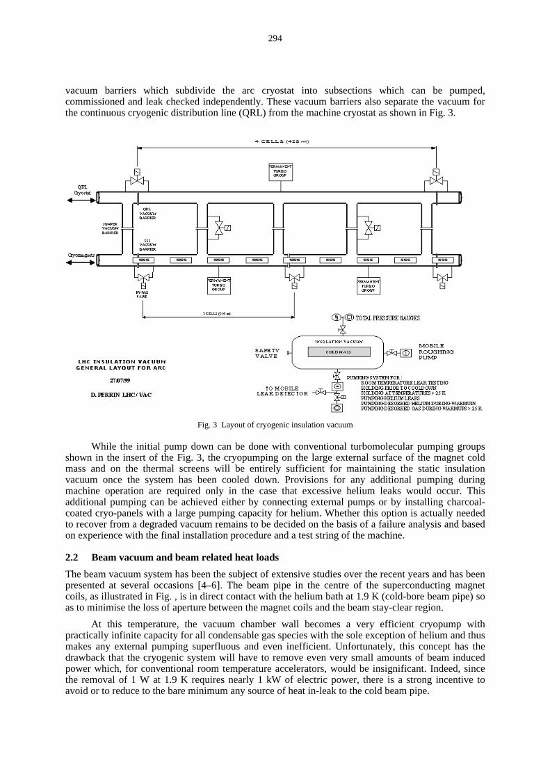
vacuum barriers which subdivide the arc cryostat into subsections which can be pumped,commissioned and leak checked independently. These vacuum barriers also separate the vacuum forthe continuous cryogenic distribution line (QRL) from the machine cryostat as shown in Fig. 3.
Fig. 3 Layout of cryogenic insulation vacuum
While the initial pump down can be done with conventional turbomolecular pumping groupsshown in the insert of the Fig. 3, the cryopumping on the large external surface of the magnet coldmass and on the thermal screens will be entirely suff icient for maintaining the static insulationvacuum once the system has been cooled down. Provisions for any additional pumping duringmachine operation are required only in the case that excessive helium leaks would occur. Thisadditional pumping can be achieved either by connecting external pumps or by installi ng charcoal-coated cryo-panels with a large pumping capacity for helium. Whether this option is actually neededto recover from a degraded vacuum remains to be decided on the basis of a failure analysis and basedon experience with the final installation procedure and a test string of the machine.
2.2 Beam vacuum and beam related heat loads
The beam vacuum system has been the subject of extensive studies over the recent years and has beenpresented at several occasions [4–6]. The beam pipe in the centre of the superconducting magnetcoils, as ill ustrated in Fig. , is in direct contact with the helium bath at 1.9 K (cold-bore beam pipe) soas to minimise the loss of aperture between the magnet coils and the beam stay-clear region.
At this temperature, the vacuum chamber wall becomes a very eff icient cryopump withpractically infinite capacity for all condensable gas species with the sole exception of helium and thusmakes any external pumping superfluous and even ineff icient. Unfortunately, this concept has thedrawback that the cryogenic system will have to remove even very small amounts of beam inducedpower which, for conventional room temperature accelerators, would be insignificant. Indeed, sincethe removal of 1 W at 1.9 K requires nearly 1 kW of electric power, there is a strong incentive toavoid or to reduce to the bare minimum any source of heat in-leak to the cold beam pipe.
295
Fig. 4 Beam-induced losses in the LHC
Four distinct beam and vacuum related heat sources to the 1.9 K system can be identified asshown in Fig. 4 and these will be discussed in more detail i n the following sections:
i) Synchrotron radiation
Due to the centripetal acceleration in the bending magnets the beams will emit a synchrotronradiation flux of about 1017 photons s-1 m-1 with a criti cal energy of the photon spectrum of 45 eVequivalent to a distributed linear power of 0.2 W m-1. For LHC as a whole, this amounts to 7.6 kW.
ii ) Image currents from the beam
The inner wall of the beam pipe must conduct the image currents of the beams, which maydissipate typically 0.05 W m-1 per beam duct. This power due to image currents depends directly onthe resistivity ρw of the vacuum chamber wall material. To limit this heat load, but also to avoidresistive wall i nstabilit y, the resistivity of the vacuum chamber has to be low. For the LHC this can beachieved by coating the inner surface of the stainless steel beam pipe with a thin copper layer and byprofiting, furthermore, from the fact that at low temperature the resistivity of high-purity copper isstrongly reduced and can be by a factor of 103 better than for stainless steel.
iii ) Photo-electrons and multipacting
Beam induced multipacting can arise through an oscill atory motion of a cloud of photo-electrons and of low energy secondary electrons bouncing back and forth between opposite vacuumchamber walls during successive passages of proton bunches [7]. Due to the strong electric field ofthe dense proton beam these electrons will be accelerated and transfer their energy to the cold wall . Inthe LHC the beam pipe radius rp, the bunch intensity Nb and the bunch spacing Lbb are such that thewall -to-wall multipacting threshold corresponds to about 1/4 of the nominal intensity [8]. Themagnitude of the heat load depends on several parameters as will be discussed in a later section but acrude estimate indicates a value of 0.2 W/m.
iv) Beam loss by nuclear scatteringNuclear scattering of the high-energy protons on the residual gas generates an unavoidable
continuous flux of high-energy particles, which are lost from the circulating beams. Even under idealconditions there remains a small fraction of scattered protons which can not be absorbed in acontrolled way by the dedicated set of collimators in the beam cleaning insertions (see Fig. 1). Theseparticles escape from the aperture of the machine and penetrate through the cold bore into themagnets where they are lost. This flux of high-energy protons creates a shower of secondary particles,which are ultimately absorbed in the 1.9 K magnet system. The continuous heat input to the cryogenicsystem is directly proportional to the gas density and hence the maximum allowed value defines anupper limit of the gas density in the beam pipe. The beam lifetime τ, due to nuclear scattering (thecross section for 7-TeV protons on hydrogen atoms is σ ~ 5 10-30 m2) is given by
0.001
0.01
0.1
1
0 1 2 3 4 5 6 7 8
Pow
er (
W/m
/bea
m)
Beam energy (TeV)
resistive
total
nuclear scattering (100 h)
s.r. photoelectrons
296
1
τ= cσ n (1)
where c is the speed of light and n the gas density. The linear power load, P (W/m), is proportional tothe beam current I, the beam energy E and can be expressed directly in terms of the beam-gas li fetime
)h(
)A()TeV(93.0
ττIE
c
EIP == (2)
For the first time in an accelerator, beam loss due to nuclear scattering on the residual gas represents anon-negligible heat load. The machine design includes therefore a nuclear scattering allowance of~0.1 W/m for the two beams. Consistent with this requirement a beam lifetime of ~100 hours hasbeen chosen which in turn implies that the H2 density must be ≤ 1 × 10¹⁵ molecules m-3 (e.g. equivalentto a pressure of ≤ 1 × 10⁻⁹ Torr at 10 K). A correspondingly lower density is required for heavier gasesas is shown in Table 2 where the limits of the molecular densities for some common gas species havebeen li sted.
Table 2Relative cross sections and maximum gas densities for different gas species
Gas S/sH2 N (m-3) for ττ = 100 h
H2 1 1 1015
He 1.26 7.8 1014
CH4 5.4 1.8 1014
H2O 5.4 1.8 1014
CO 7.8 1.2 1014
CO2 12.2 8.0 1013
Among the four heat sources shown in Fig. 4 synchrotron radiation, image currents and photo-electrons can be intercepted at a thermodynamically-more-eff icient temperature of 20 K. This can beachieved by inserting in the cold bore vacuum chamber a thermally insulated ‘beam screen’ , which isactively cooled by gaseous helium. The fourth component, due to scattered high-energy protons,cannot be intercepted by this screen and must be included in the cryogenic budget for the 1.9 Ksystem. This effect, which has a practical importance for the first time in the LHC, defines a ‘ li fetimelimit ’ of 1015 H2 molecules m-3 for the maximum average gas density in the LHC arcs. It must be notedthat in the exceptional case of a limited region with a very high pressure, e.g. for a helium leak, therelated beam loss may even trigger a magnet to quench.
The section of the beam screen with its two cooling tubes is shown in Fig. 5. In order not toloose the benefit of the cryopumping on the 1.9 K cold bore, the screen has narrow pumping slotsalong its length which enable gas molecules to leave the beam channel proper and to be adsorbed onthe cold bore wall . The importance of cryosorbing gas molecules on a surface, which is screened fromthe effects of the beam, will be discussed in the following section.
3. PRIMARY DESORPTION BY SYNCHROTRON RADIATION
At 7 TeV, the criti cal energy of the synchrotron radiation spectrum is ~45 eV and the radiated powerrepresents a heat load of 0.2 W/m per beam. The actively-cooled beam screen intercepts this power sothat it does not load the 1.9 K system. For vacuum reasons, the screen has to be partiall y transparentso that molecules desorbed by the synchrotron radiation can escape from the beam channel and bepumped permanently on the cold bore surface as ill ustrated in Fig. 5.
297
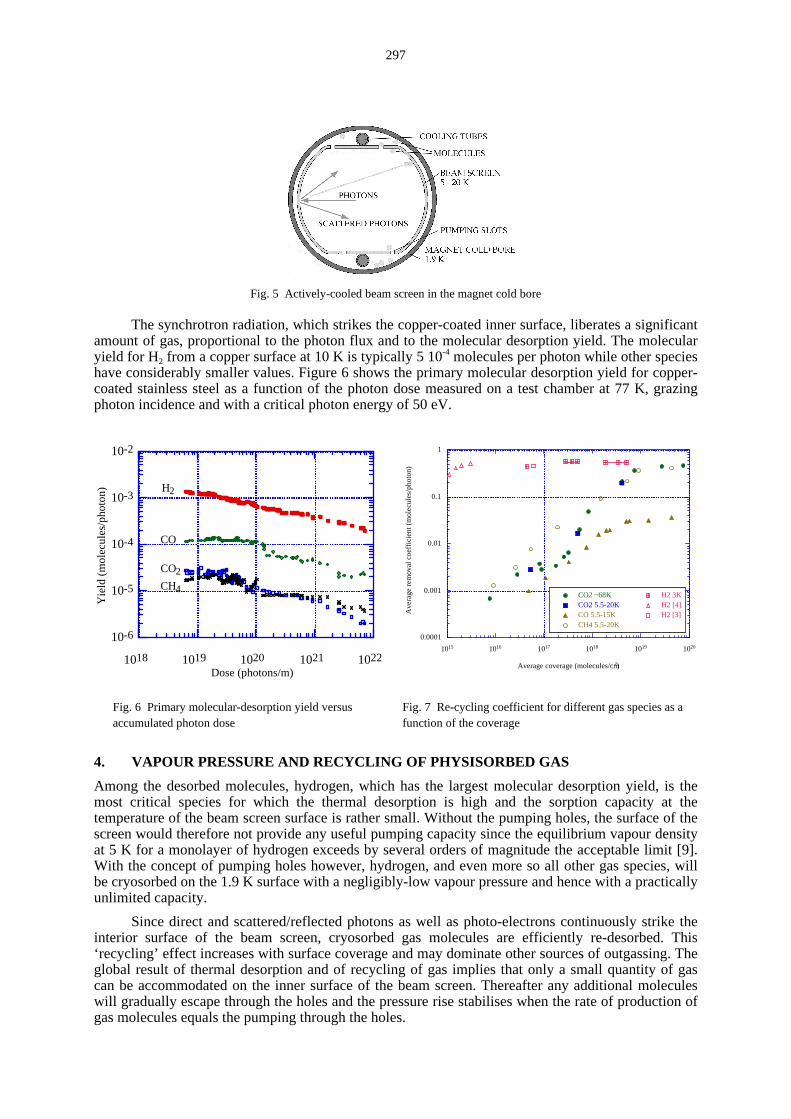
Fig. 5 Actively-cooled beam screen in the magnet cold bore
The synchrotron radiation, which strikes the copper-coated inner surface, liberates a significantamount of gas, proportional to the photon flux and to the molecular desorption yield. The molecularyield for H2 from a copper surface at 10 K is typically 5 10-4 molecules per photon while other specieshave considerably smaller values. Figure 6 shows the primary molecular desorption yield for copper-coated stainless steel as a function of the photon dose measured on a test chamber at 77 K, grazingphoton incidence and with a criti cal photon energy of 50 eV.
Fig. 7 Re-cycling coeff icient for different gas species as afunction of the coverage
4. VAPOUR PRESSURE AND RECYCLING OF PHYSISORBED GAS
Among the desorbed molecules, hydrogen, which has the largest molecular desorption yield, is themost criti cal species for which the thermal desorption is high and the sorption capacity at thetemperature of the beam screen surface is rather small . Without the pumping holes, the surface of thescreen would therefore not provide any useful pumping capacity since the equili brium vapour densityat 5 K for a monolayer of hydrogen exceeds by several orders of magnitude the acceptable limit [9].With the concept of pumping holes however, hydrogen, and even more so all other gas species, willbe cryosorbed on the 1.9 K surface with a negligibly-low vapour pressure and hence with a practicallyunlimited capacity.
Since direct and scattered/reflected photons as well as photo-electrons continuously strike theinterior surface of the beam screen, cryosorbed gas molecules are eff iciently re-desorbed. This‘recycling’ effect increases with surface coverage and may dominate other sources of outgassing. Theglobal result of thermal desorption and of recycling of gas implies that only a small quantity of gascan be accommodated on the inner surface of the beam screen. Thereafter any additional moleculeswill gradually escape through the holes and the pressure rise stabili ses when the rate of production ofgas molecules equals the pumping through the holes.
0.0001
0.001
0.01
0.1
1
1015 1016 1017 1018 1019 1020
CO2 ~68K CO2 5.5-20KCO 5.5-15KCH4 5.5-20K
H2 3KH2 [4]H2 [3]A
vera
ge
re
mo
val c
oe
ffic
ien
t (m
ole
cule
s/p
ho
ton
)
Average coverage (molecules/cm2)
10-6
10-5
10-4
10-3
10-2
1018 1019 1020 1021 1022
Yie
ld (
mo
lecu
les/
ph
oto
n)
Dose (photons/m)
H2
CO
CO2
CH4
298
Experimental data for the recycling effect have been obtained from an experiment at the VEPP-2M storage ring at the Budker Institute of Nuclear Physics (BINP) in Novosibirsk, Russia [10]. In thisexperiment a sample can be loaded initiall y with a known quantity of a gas. Subsequently, the sampleis exposed to a known number of photons and the quantity of molecules remaining after this exposureis measured during its warm-up. The results of this experiment are given in Fig. 7 where it can beseen that the recycling of H2 by synchrotron radiation photons is a very pronounced effect already at acoverage well below a monolayer (< 1015 molecules cm-2).
It is interesting to note that this recent result for the hydrogen re-cycling coeff icient is in goodagreement with observations made previously when investigating the problem of an abnormalhydrogen vapour pressure in condensation cryopumps [11]. It was observed that exposure to roomtemperature thermal radiation can desorb very strongly hydrogen condensed on a substrate at 2.3 K.Indeed, extrapolating from these earlier measurements to LHC conditions, the synchrotron radiationpower density on a cold bore without screen (~ 0.14 W cm-2) could increase the saturated vapourpressure to a value comparable to the li fetime limit .
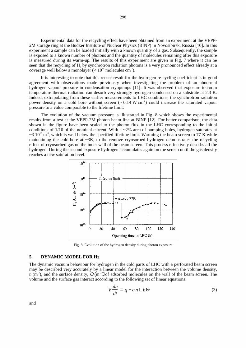
The evolution of the vacuum pressure is ill ustrated in Fig. 8 which shows the experimentalresults from a test at the VEPP-2M photon beam line at BINP [12]. For better comparison, the datashown in the figure have been scaled to the photon flux in the LHC corresponding to the initialconditions of 1/10 of the nominal current. With a ~2% area of pumping holes, hydrogen saturates at~3 1013 m-3, which is well below the specified li fetime limit . Warming the beam screen to 77 K whilemaintaining the cold-bore at ~3K, to the remove cryosorbed hydrogen demonstrates the recyclingeffect of cryosorbed gas on the inner wall of the beam screen. This process effectively desorbs all thehydrogen. During the second exposure hydrogen accumulates again on the screen until the gas densityreaches a new saturation level.
Fig. 8 Evolution of the hydrogen density during photon exposure
5. DYNAMIC MODEL FOR H2
The dynamic vacuum behaviour for hydrogen in the cold parts of LHC with a perforated beam screenmay be described very accurately by a linear model for the interaction between the volume density,n (m-3), and the surface density, Θ (m-2), of adsorbed molecules on the wall of the beam screen. Thevolume and the surface gas interact according to the following set of linear equations:
Vdn
dt= q − an+ bΘ (3)
and
299
FdΘdt
= cn − bΘ . (4)
Here, V is the volume and F is the net wall area per unit length of the vacuum system. The parametersa, b, c and q represent the following physical quantities:
i) q represents a source of gas, here in particular the photon induced desorption rate determined
by the product of the desorption yield, η (molecules/photon), and of the photon flux, Γ.
, hence
q = η Γ.
(molecules s-1m-1). In more general terms q can include any source of chemisorbed gas e.g.by ion- or by electron-stimulated desorption.
ii ) a (m2 s-1) describes the total pumping on the surface of the wall and in particular through thearea of the holes in the beam screen. It can be expressed as
a = 1
4v F (s+ f ) (5)
where v is the average molecular velocity, s the sticking probabilit y of the molecules on the beamscreen and f is the fraction of the total surface of the beam screen with pumping holes, note that f<<1.
iii ) b represents gas originating from a physisorbed surface phase, Θ, by thermal- and by photon-induced desorption. In contrast to q, this is not a source of 'new' gas but constitutes a surface phaseinteracting through adsorption and desorption with the gas in the volume.
The thermal contribution to b [13] may be expressed as the molecular vibration frequencyνο = 1013 s-1 multiplied with a Boltzmann factor
e− E
kT (6)
characterised by its activation energy E and by the temperature T.
The photon-induced desorption process can be expressed as Γκ�
, where κ is the re-cyclingcross-section in m2 per photon, thus
Γκν�
+=−
kT
E
o eFb . (7)
iv) c is the rate of adsorption of gas molecules on the surface of the beam screen only. This effectis proportional to the sticking probabilit y of the molecules, s,
c =1
4v sF . (8)
This dynamic model contains a reasonably small number of parameters, which, for simplicity may beassumed to be constant. In particular it implies a linear adsorption isotherm.
n
eF
Fsvn
b
c
kTE
o ΓκνΘ
�
+==
−4
1 . (9)
Here Θ (n) depends on the re-cycling cross-section as well as on the photon flux. Therefore, theisotherm and the equili brium surface coverage for a given volume gas density will depend on thesespecific conditions (i.e. on the beam current) which effectively reduce the sojourn time of anyphysisorbed molecules on the surface.
300
As shown in Fig. 9 the experimental data presented in Fig. 8, can indeed be described in a verysatisfactory manner by this simple model by choosing a small number of free parameters only, seeTable 3. Parameters shown in bold face have been adapted to best fit the data. The fraction ofpumping slots f, takes into account the Clausing factor due to the wall thickness of the beam screen.
Fig. 9 Comparison of experimental data with the dynamicmodel for H2 density (m-3) as a function of time
Fig. 10 Surface density of H2 molecules normalised to amonolayer coverage as a function of time
Table 3List of parameters.
Desorption yield η 5 × 10⁻⁴ molecules/photon
Screen temperature T 10 K
Linear photon flux (200 mA) Γ.
3.14 × 10¹⁶ photons/s/m
Sticking probability σ 0.6
Monolayer capacity 3 × 10¹⁹ molecules/m2
Re-cycling coefficient κ 5 × 10-21 m2
Activation energy Ε 800 cal/mole or 0.035 eV/molecule
Specific surface area F 0.14 m
Fraction of pumping slots f 1.28%
Specific volume V 1.3 × 10⁻³ m2
The model provides in addition to the volume density also the surface density of gas, which isshown in Fig. 10. There it can be observed that the final coverage obtained remains indeed well belowa monolayer as a result of the strong recycling of gas molecules.
In equili brium conditions, when the volume and surface densities no longer change with time,the volume density is simply given by
fFvca
qnequ
4
1Γη
�
=−
= (10)
301
and depends solely on the primary desorption by synchrotron radiation and on the pumping throughthe holes in the beam screen.
6. ION STIMULATED DESORPTION AND PRESSURE INSTABILITY
Ionization of the residual gas molecules will produce ions, which are ejected by the positi ve beampotential and accelerated towards the beam screen. The final impact energy of the ions may be up to300 eV in the arcs of the LHC. As with photons, the energetic ions are very effective in desorbingtightly-bound gas molecules, a process, which is characterised by the molecular, desorption yield, ηi(molecules per ion). Desorbed molecules may in turn be ionised and thus increase the desorption rate.This positi ve feedback can lead to the so-called ‘ ion-induced pressure instabilit y’ known fromprevious experience with the Intersecting Storage Rings (ISR) at CERN [14]. As a result of thisfeedback mechanism the pressure increases with beam current from the initial value, P0, as
PI =P0
1− η I
(η I )crit
. (11)
Since the electric charge of the beam is strongly concentrated in 2835 individual, shortbunches, the resulting instantaneous peak electric field amounts to several kV. The final energy of theions at the impact on the vacuum chamber wall can reach several hundred eV depending on the beamintensity and the type of ion. Fig. 11 shows the impact energies calculated for H2 He, CH4, CO andCO2 ions as a function of the average beam intensity. Because of the bunched structure of the beam,light ions may gain considerably more energy than heavier ones.
0
500
1000
1500
2000
0 0.2 0.4 0.6 0.8 1
mass 2mass 4mass 16mass 28mass 44
Ion
imp
act
en
erg
y (
eV
)
Beam current (A)
Fig. 11 Ion impact energy as a function of beam current
The pressure runaway depends criti cally on the local cleanliness of the surface, through the ion-induced molecular desorption yield, ηi, and on the local pumping speed. The stabilit y limit i sexpressed by the condition that the product of beam current I and of the molecular desorption yieldmust be less than a criti cal value given by the effective pumping speed of the system, Seff
effcrit)( Se
Ii ση = (12)
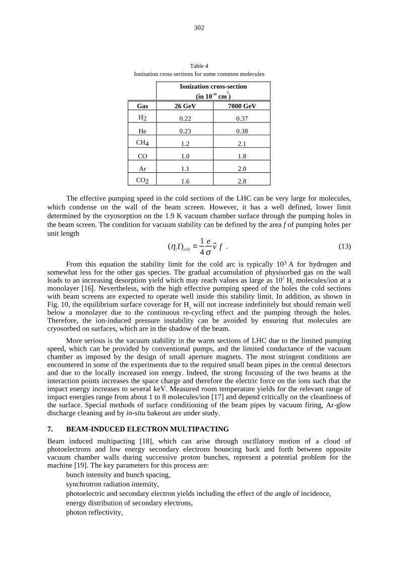
where e is the electron charge and σ the ionisation cross section of the residual gas molecules for highenergy protons. According to Eq. (12) the pressure will double at half the criti cal value. Ionisationcross sections for high energy protons for some common gas molecules are given in Table 4 [15].
302
Table 4Ionisation cross sections for some common molecules
Ionization cross-section
(in 10-18 cm2
)Gas 26 GeV 7000 GeV
H2 0.22 0.37
He 0.23 0.38
CH4 1.2 2.1
CO 1.0 1.8
Ar 1.1 2.0
CO2 1.6 2.8
The effective pumping speed in the cold sections of the LHC can be very large for molecules,which condense on the wall of the beam screen. However, it has a well defined, lower limitdetermined by the cryosorption on the 1.9 K vacuum chamber surface through the pumping holes inthe beam screen. The condition for vacuum stabilit y can be defined by the area f of pumping holes perunit length
(ηi I )crit =1
4e
σv f . (13)
From this equation the stabilit y limit for the cold arc is typically 103 A for hydrogen andsomewhat less for the other gas species. The gradual accumulation of physisorbed gas on the wallleads to an increasing desorption yield which may reach values as large as 103 H2 molecules/ion at amonolayer [16]. Nevertheless, with the high effective pumping speed of the holes the cold sectionswith beam screens are expected to operate well i nside this stabilit y limit . In addition, as shown inFig. 10, the equili brium surface coverage for H2 will not increase indefinitely but should remain wellbelow a monolayer due to the continuous re-cycling effect and the pumping through the holes.Therefore, the ion-induced pressure instabilit y can be avoided by ensuring that molecules arecryosorbed on surfaces, which are in the shadow of the beam.
More serious is the vacuum stabilit y in the warm sections of LHC due to the limited pumpingspeed, which can be provided by conventional pumps, and the limited conductance of the vacuumchamber as imposed by the design of small aperture magnets. The most stringent conditions areencountered in some of the experiments due to the required small beam pipes in the central detectorsand due to the locally increased ion energy. Indeed, the strong focussing of the two beams at theinteraction points increases the space charge and therefore the electric force on the ions such that theimpact energy increases to several keV. Measured room temperature yields for the relevant range ofimpact energies range from about 1 to 8 molecules/ion [17] and depend criti cally on the cleanliness ofthe surface. Special methods of surface conditioning of the beam pipes by vacuum firing, Ar-glowdischarge cleaning and by in-situ bakeout are under study.
7. BEAM-INDUCED ELECTRON MULTIPACTING
Beam induced multipacting [18], which can arise through oscill atory motion of a cloud ofphotoelectrons and low energy secondary electrons bouncing back and forth between oppositevacuum chamber walls during successive proton bunches, represent a potential problem for themachine [19]. The key parameters for this process are:
bunch intensity and bunch spacing,synchrotron radiation intensity,photoelectric and secondary electron yields including the effect of the angle of incidence,energy distribution of secondary electrons,photon reflectivity,
303
beam screen shape and dimensions as well asexternal electric and magnetic fields.
The average value of energy transferred to electrons may be of the order of 200 eV. Undersituations where the secondary electron yield exceeds unity, the electron cloud may then growindefinitely and, as a consequence, provoke electron-stimulated gas desorption. A first criterion forthe onset of multipacting is obtained from the necessary condition that the transit time of electronsfrom wall to wall must be equal or less than the time between the passage of successive bunches sothat the electron cloud can move in synchronism with the beam
Nb =rp
2
re Lbb. (14)
Here rp (m) is the beam pipe radius, Lbb is the distance between bunches and re the classical electronradius. In the LHC the determining parameters li ke the beam screen radius, the bunch intensity andthe bunch spacing are such that the wall -to-wall multipacting condition is satisfied between about 1/4to 1/3 of the nominal current [20].
The consequence for the machine operation can be an additional heat load due to the powerdeposited by the photo-electrons in the wall of the cold vacuum system, electron-stimulated gasdesorption and finally coherent beam oscill ations of the proton beam with the electron cloud leadingto emittance growth and ultimately to beam loss. These effects have been studied extensively over thepast years and it was concluded that an average heat load of 0.2 W/m should be included in thecryogenic budget. To reduce the electron cloud effect, one must find ways to reduce the productionrate of photo-electrons and to achieve a low secondary electron yield at the internal surface of thevacuum chamber and of the beam screen [21].
A second important condition, which has to be satisfied, is that the energy transfer to theelectrons is suff iciently large to obtain a secondary electron yield, which exceeds unity. Detailednumerical simulations for the nominal operating conditions have shown that in case of a secondaryelectron yield exceeding 1.3 to 1.4 the electron cloud could grow indefinitely until it finally saturatesdue to non-linear effects and space charge [22].
Secondary electron yield data for ‘ technical’ Cu and Al surfaces measured on samples in thelaboratory indicate that for both materials a unit yield is exceeded at an electron energy of less than 50eV [23] and that the respective yield versus energy curves peak at 2.2 and 2.7 between 300 and 450eV respectively. Therefore, to be safe against electron multipacting, it will be essential to provide avacuum chamber surface with a lower secondary electron yield and primarily for this reasonaluminium has been excluded as a material for beam pipes. Even for the more favourable materialsli ke copper or stainless steel, it will be necessary to reduce their secondary electron yield below thiscriti cal value by in-situ conditioning, i.e. beam scrubbing, with synchrotron radiation.
8. MECHANICAL DESIGN ASPECTS
8.1 Beam screen
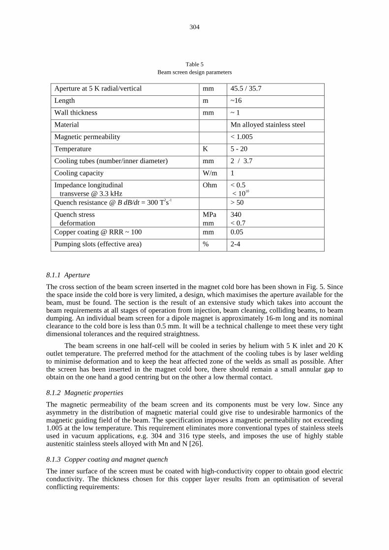
The beam screen is cooled by two longitudinal cooling tubes placed in the vertical plane above andbelow the beam where this is acceptable from the point of view of the required beam aperture. Formechanical and magnetic reasons, the screen must be made of a low-permeabilit y stainless steel,approximately 1 mm thick. A detailed description of the required electric, magnetic and mechanicalcharacteristics of the beam screen may be found in [23] and [24]. The inner wall , exposed to theelectric field of the beam, is coated with a 0.05 mm layer of high-conductivity copper to keep theelectric impedance low [25]. With this mechanical design an optimum compromise has to be foundbetween many, partiall y confli cting requirements. For example, the good electric conductivity of thecopper confli cts with the magnetic forces produced by eddy currents during a magnet quench. Theseforces have been evaluated at several tonnes per m and impose the mechanical strength of the screen.A li st of main design parameters is given in Table 5.
304
Table 5Beam screen design parameters
Aperture at 5 K radial/vertical mm 45.5 / 35.7
Length m ~16
Wall thickness mm ~ 1
Material Mn alloyed stainless steel
Magnetic permeabilit y < 1.005
Temperature K 5 - 20
Cooling tubes (number/inner diameter) mm 2 / 3.7
Cooling capacity W/m 1
Impedance longitudinal transverse @ 3.3 kHz
Ohm < 0.5 < 1010
Quench resistance @ B dB/dt = 300 T2s-1 > 50
Quench stress deformation
MPamm
340< 0.7
Copper coating @ RRR ~ 100 mm 0.05
Pumping slots (effective area) % 2-4
8.1.1 Aperture
The cross section of the beam screen inserted in the magnet cold bore has been shown in Fig. 5. Sincethe space inside the cold bore is very limited, a design, which maximises the aperture available for thebeam, must be found. The section is the result of an extensive study which takes into account thebeam requirements at all stages of operation from injection, beam cleaning, colli ding beams, to beamdumping. An individual beam screen for a dipole magnet is approximately 16-m long and its nominalclearance to the cold bore is less than 0.5 mm. It will be a technical challenge to meet these very tightdimensional tolerances and the required straightness.
The beam screens in one half-cell will be cooled in series by helium with 5 K inlet and 20 Koutlet temperature. The preferred method for the attachment of the cooling tubes is by laser weldingto minimise deformation and to keep the heat affected zone of the welds as small as possible. Afterthe screen has been inserted in the magnet cold bore, there should remain a small annular gap toobtain on the one hand a good centring but on the other a low thermal contact.
8.1.2 Magnetic properties
The magnetic permeabilit y of the beam screen and its components must be very low. Since anyasymmetry in the distribution of magnetic material could give rise to undesirable harmonics of themagnetic guiding field of the beam. The specification imposes a magnetic permeabilit y not exceeding1.005 at the low temperature. This requirement eliminates more conventional types of stainless steelsused in vacuum applications, e.g. 304 and 316 type steels, and imposes the use of highly stableausteniti c stainless steels alloyed with Mn and N [26].
8.1.3 Copper coating and magnet quench
The inner surface of the screen must be coated with high-conductivity copper to obtain good electricconductivity. The thickness chosen for this copper layer results from an optimisation of severalconfli cting requirements:
305
A suff iciently thick, high conductivity layer will reduce the power dissipated by image currents,provide a low electric impedance and thus limit the growth rate for the transverse resistive-wall beaminstabilit y. A larger power dissipation would require more or larger helium cooling channels and thuscomplicate the design or reduce the vertical aperture. On the other hand, a thicker copper layer willentail l arger eddy currents and electro-mechanical forces during a magnet quench and hence require amechanically stronger, i.e. thicker beam screen, which again reduces the aperture. The compromise is0.05 mm of copper and a ∼1-mm wall thickness for the stainless steel tube. The stresses induced inthe beam screen during a magnet quench, results in a ~0.7-mm deflection in the horizontal plane.Among the different methods for producing the copper layer roll -bonding of copper onto stainlesssteel strips is the most cost effective for a series production. The coated strip is then shaped into thefinal profile in a continuous tube-forming machine with a single longitudinal laser weld.
8.2 Beam screen interconnects
The mechanical design of the cold arc vacuum system requires a large number of interconnections forthe beam vacuum between the beam screens of adjacent magnets. Following the proven design of theLEP-type RF-finger contacts a new concept has been developed which takes into account the largethermal contraction (approx. 45 mm) between room temperature and operating temperature [27]. Animportant design criterion to be met is the requirement of installation and alignment of the longcryomagnets without the risk of damaging the delicate finger contacts even in case of lateral offsets ofup to 4 mm. The principle of the design is shown in Fig. 12. To by-pass the RF bellows, the beamscreen cooling tubes are joined in the insulation vacuum enclosure by a flexible tubing. With thisconcept the risk of a helium leak affecting the criti cal beam vacuum can be minimised. In the finalcold position the required smooth and well -defined electric contact is established with a controlledforce of the RF contact fingers.
9. SUMMARY
The design of the LHC vacuum system must satisfy a number of requirements, which depend not onlyon vacuum issues but also on considerations of both beam impedance and heat losses into thecryogenic system and/or the superconducting magnets. The pumping relies entirely on cryopumpingof the 1.9 K cold bore surface, which offers a practically unlimited capacity for all gases excepthelium. The detailed design of the vacuum system is strongly influenced by the relatively largeamount of synchrotron radiation, which represents a significant source of photon-stimulatedoutgassing, creates photoelectrons and is thus a driving mechanism for beam-induced multipacting.The beam induced heat load to the 1.9 K system has a large importance for the design and imposes byitself the presence of an actively-cooled beam screen. The intense proton bunches with their high peak
Fig. 12 Beam vacuuminterconnect
306
current lead to energetic ions which strike the walls and may cause ion-induced desorption and ion-induced pressure rise. Due to the cryogenic temperature of the walls, most molecular species arestrongly cryosorbed and stick to the surface. This effect leads to a build-up of layers of cryosorbedgas, which in turn may desorb either thermally (vapour pressure effect) or by photon-stimulateddesorption (re-cycling effect).
ACKNOWLEDGEMENTS
The description of the LHC vacuum system presented here reflects the work of many colleagues inthe LHC Vacuum Group. The important contributions, in particular from the groups LHC-CRI, EST-SM and SL-AP are also gratefully acknowledged.
REFERENCES[1] The LHC Study Group, The Large Hadron Colli der, Conceptual Design, CERN/AC/95-05
(1995).
[2] L. Evans and Ph. Lebrun, Progress in Construction of the LHC, LHC Project Report 239(1998).
[3] J.C. Brunet, et al., LHC-Project Report 280 and PAC-99, New York, (1999).
[4] A.G. Mathewson et al., EPAC-94, London, 1994.
[5] A.G. Mathewson et al., PAC-95, Dallas, 1995.
[6] O. Gröbner, Vacuum, 45, 767 (1995).
[7] O. Gröbner, 10th Int. Conf. On High Energy Accelerators, Protvino, July 1977.
[8] O. Gröbner, PAC-97, Vancouver 1997.
[9] E. Wallén, J. Vac. Sci. Technol. A 15(2), march/April 1997.
[10] V.V. Anashin, O.B. Malyshev, R. Calder and O. Gröbner, Vacuum 53, 269-272 (1999).
[11] C. Benvenuti, R. Calder and G. Passardi, J. Vac. Sci. Technol. 13, 6, Nov/Dec. (1976).
[12] R. Calder et al., J. Vac. Sci. Technol. A 14(4), Jul/Aug 1996.
[13] P. Redhead et al., The Physical Basis of Ultrahigh Vacuum, AIP (1993).
[14] O. Gröbner and R. Calder, IEEE Trans. Nucl. Sci., NS-20, 760, 1973.
[15] F. Rieke and W. Prepejchal, Phys. Rev. A 6, 1507 (1972).
[16] J.C. Barnard, I. Bojko and N. Hill eret, Vacuum 47, 4, 347 (1996).
[17] I.R. Colli ns, O. Gröbner, P. Lepeule and R. Veness, EPAC-98, Stockholm (1998).
[18] O. Gröbner, 10th Int. Conf. on High Energy Accelerators, Protvino, July 1977.
[19] F. Zimmermann, LHC Project Report 95, 27 February 1997.
[20] O. Gröbner, PAC-97, Vancouver, 1997.
[21] V. Baglin, I.R. Colli ns and O. Gröbner, EPAC-98, Stockholm, 1998.
[22] O. Brüning et al., PAC-99, New York (1999).
[23] A. Poncet et al., EPAC-94, London, 1994.
[24] P. Cruikshank et al., PAC-97, Vancouver, 1997.
[25] F. Ruggiero, R. Caspers and M. Morvill o, PAC-97, Vancouver, 1997.
[26] S. Sgobba and G. Hochoertler, International Congress Stainless Steel, to be published (1999).