28
Koike Aronson, Inc./Ransome Koike Aronson, Inc./Ransome The Most Complete Line in the Industry

Koike Aronson, Inc./RansomeKoike Aronson, Inc./Ransome
The Most Complete Line in the Industry


Table of ContentsHow to Size a Manipulator.............4
Aronson Series
Locust.............8
Scarab........….10
Ransome Series
Model 44..........12
Model 66 - 1212..........14
Model SHD - XXHD…….….16
Special
Seam Welders..........18
Side Beams..........20
Options..........22

PAGE 4
How to Size a ManipulatorLift & Reach The lift and reach requirement are determined bythe most extreme vertical and horizontal arc location.This is based on the work envelope size. Lift and reachdimensions are measure from the centerline of themast/upright and boom/ram. There is a minimum andmaximum dimension, the lift and reach size isrepresents the total range provided. A typical weldingset-up is shown in the sketch below. The distance tothe top of the vessel above the floor can be determinedby first finding “side b” of the triangle a-b-c, withknown values for “a” and “c” using the formula b = √a²- c². Then add the value of “b” to the Axle Heightabove floor, plus the “R” Radius of the vessel. Next addthe distance from the Arc to the Centerline of theBoom. This will give you the maximum required for theLift Range. Follow the same procedure to find Archeight needed for the smallest vessels.
Options:Standard Manipulators include lift and reach
capability only. Travel cars, travel rail, operator seats,catwalks, cross slides, welding equipment, mast rotationand seam trackers are all examples of options that mustbe specified when ordering a manipulator.
Load Capacity:Koike Aronson/Ransome Manipulators have a rated
load capacity that must be considered. This load isexpressed as a value at either or both ends of theboom/ram, and is rated directly at the end, no overhung capacity is stated. All additional weights,including operator, catwalks, operator chairs, cross slidesand welding equipment must be considered whencalculating the weight capacity required. All loadratings vary depending on lift and reach specified, referto the manipulator load capacity table on page 5.
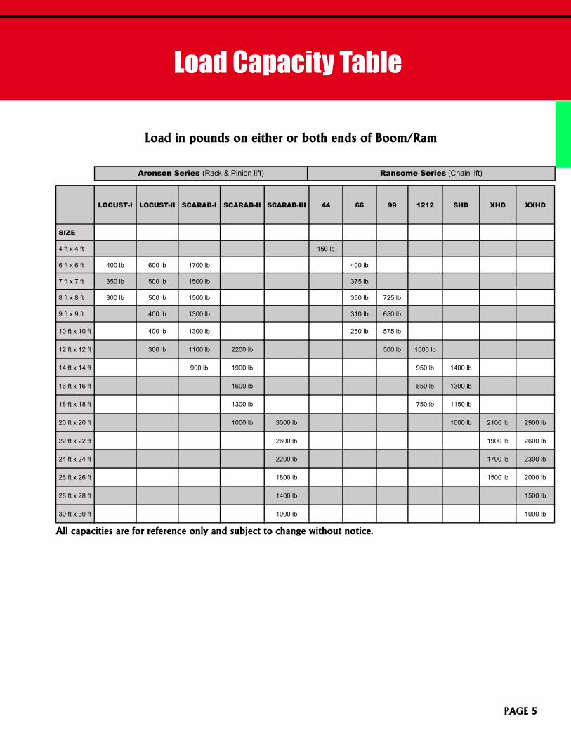
Load Capacity Table
PAGE 5
All capacities are for reference only and subject to change without notice.
LOCUST-I LOCUST-II SCARAB-I SCARAB-II SCARAB-III 44 66 99 1212 SHD XHD XXHD
SIZE
4 ft x 4 ft 150 lb
6 ft x 6 ft 400 lb 600 lb 1700 lb 400 lb
7 ft x 7 ft 350 lb 500 lb 1500 lb 375 lb
8 ft x 8 ft 300 lb 500 lb 1500 lb 350 lb 725 lb
9 ft x 9 ft 400 lb 1300 lb 310 lb 650 lb
10 ft x 10 ft 400 lb 1300 lb 250 lb 575 lb
12 ft x 12 ft 300 lb 1100 lb 2200 lb 500 lb 1000 lb
14 ft x 14 ft 900 lb 1900 lb 950 lb 1400 lb
16 ft x 16 ft 1600 lb 850 lb 1300 lb
18 ft x 18 ft 1300 lb 750 lb 1150 lb
20 ft x 20 ft 1000 lb 3000 lb 1000 lb 2100 lb 2900 lb
22 ft x 22 ft 2600 lb 1900 lb 2600 lb
24 ft x 24 ft 2200 lb 1700 lb 2300 lb
26 ft x 26 ft 1800 lb 1500 lb 2000 lb
28 ft x 28 ft 1400 lb 1500 lb
30 ft x 30 ft 1000 lb 1000 lb
Load in pounds on either or both ends of Boom/Ram
Aronson Series (Rack & Pinion lift) Ransome Series (Chain lift)

All Ransome model manipulators come standard with MANUAL mast rotation.Stationary and powered mast options available.
All Aronson model manipulators come standard with STATIONARY mast. Manual and powered mast options available.
LOCUST-I LOCUST-II SCARAB-I SCARAB-II SCARAB-III 44 66 99 1212 SHD XHD XXHD
SIZE
6 ft x 6 ft A, B, F A, B, G A, B, G A, B, G
7 ft x 7 ft A, B, F A, B, G A, B, G A, C, G
8 ft x 8 ft A, B, F A, C, G A, C, H A, C, G A, C, H
9 ft x 9 ft A, C, G A, C, H A, C, G A, C, H
10 ft x 10 ft A, C, G A, C, H A, C, G A, C, H
12 ft x 12 ft A, C, G C, I C, J A, C, H A, C, H
14 ft x 14 ft C, I D, I C, I C, J
16 ft x 16 ft D, J C, I D, J
18 ft x 18 ft D, J C, I D, J
20 ft x 20 ft E, J E, K D, J E, K E, K
22 ft x 22 ft E, K E, K E, K
24 ft x 24 ft E, K E, K E, K
26 ft x 26 ft E, K E, K E, K
28 ft x 28 ft E, K E, K
30 ft x 30 ft E, K E, K
Base and Car options
Aronson Series (Rack & pinion lift) Ransome Series (Chain lift)
PAGE 6
Car rail lengths available in standard lengths of 10 ft and 20 ft sections.

Koike Aronson Inc./ RansomeP.O. Box 307, Arcade, New York 14009
Phone (585) 492-2400 Fax (585) 457-3517www.koike.com PAGE 7
Model DescriptionSpeedRange
Adds to HOA / Liftrange with rail
A 33 in Gauge Car
Used for powered precision travel along a fabricated Manipulator rail. Canbe used for car travel welding and Manipulator postioning along rail length.Fabricated steel design sufficient to carry the weight of a manipulator, powersource, automatic head, controls, flux recovery system, wire reel and supportingapparatus. Completely enclosed car is powered by a 1-1⁄2 HP Drive. Power istransmitted to the precision cut gear rack pinion for positive car travel. Car rideson track ways with six sets of adjustable cam follower rollers that grip thereplaceable ways on top, bottom and sides to maintain constant alignment ofthe car. All controls for operating car are located in a pendant station. Car isequipped with track wipers.
3-150 ipm 16-¼ in
B 51-1⁄4 in Gauge Car
Used for manual or powered travel with "V" wheels on inverted angleiron fabricated Manipulator rail. Primarily used for postioningManipulator along rail length.Car is heavy-duty all welded steel fabrication. Axles rotate in heavy-dutyself-aligning pillow block bearings. Car has sufficient strength to supportand a Manipulator and automatic welding Equipment.
Manual12-5⁄8 in
C 56-1⁄2 in Gauge Car
Used for manual or powered travel on 90#/ yard standard crane rail.Can be used for car travel welding and Manipulator postioning alongrail length.Car is low-slung to keep the center of gravity at a minimum. Machined carwheels will operate on a 56-½ in gauge with one set of car wheels doubleflanged; the opposing set of wheels is flat.
Manualor
2.0 - 100 ipm 22 in
D 72 in Gauge Car
Used for powered travel on 90#/ yard standard crane rail. Can be usedfor car travel welding and Manipulator postioning along rail length.Car is low-slung to keep the center of gravity at a minimum and is geardriven with power transmitted to one set of opposing wheels by directcoupling to the drive shaft of the wheels. Machined car wheels will operateon a 72 in gauge with all single flanged wheels.
2.0-100 ipm 20 in
E 84 in Gauge Car
Used for powered travel on 90#/ yard standard crane rail. Can be usedfor car travel welding and Manipulator postioning along rail length.Car is low-slung to keep the center of gravity at a minimum and is geardriven with power transmitted to one set of opposing wheels by directcoupling to the drive shaft of the wheels. Machined car wheels will operateon a 84 in gauge with one set of car wheels double flanged; the opposingset of wheels is flat.
2.0-100 ipm 29-½ in
F X-Base (self standing)82-½ in
FREE STANDING 4-LEG BASEWith leveling screws and pad on each leg. 10 in
G X-Base (self standing)120 in
FREE STANDING 4-LEG BASEWith leveling screws and pad on each leg 10 in
H X-Base (self standing)144 in
FREE STANDING 4-LEG BASEWith leveling screws and pad on each leg 10 in
I X-Base (self standing)159 in
FREE STANDING 4-LEG BASEWith leveling screws and pad on each leg 10 in
J Self Standing Base85 in Square
FREE STANDING SQUARE BASE85 in Square Base 14-¾ in
K Self Standing Base101 in Square
FREE STANDING SQUARE BASE101 in Square Base 24-½ in
All dimensions are for reference only and subject to change without notice.

PAGE 8KOIKE ARONSON, INC. / RANSOME
ARONSONSeries
Locust I & II
Features
Lift and reach ranging from 6 ft to 12 ft
Koike Aronson / Ransome gear elevated Locust seriesmanipulators are designed for safety and a trouble free long life. Allcritical mechanisms are enclosed and load carrying gear cases arewelded in place and lifetime lubricated. Both lift and reach axis areguided with concave wheels and roundways for precision movement.
For small to medium industrial applications which require a smallto medium arc travel and load capacity without the location of theoperator on the boom, the Locust series manipulators are thesolution.
Self-standing bases, travel cars and welding equipment packagesare just some of the options available.
▪ Load capacities up to600 pounds
▪ NEMA 12 Electricals
▪ Floor-base or car-trackoptions available
▪ Large variety of accessoriesand options for versatility
▪ Low voltage hand controlpendants
▪ Variable speed drives
▪ Round rail guidance on liftand reach axis
▪ Rack and pinion lift
▪ Optional mast rotation
Standard hand pendantprovided with all models

Koike Aronson Inc./ RansomeP.O. Box 307, Arcade, New York 14009
Phone (585) 492-2400 Fax (585) 457-3517www.koike.com
SpecificationsLocust
PAGE 9
All dimensions are for reference only and subject to change without notice.
Model Locust- I Locust -II6 ft x 6 ft 400 lb 600 lb
7 ft x 7 ft 350 lb 500 lb
8 ft x 8 ft 300 lb 500 lb
9 ft x 9 ft 400 lb
10 ft x 10 ft 400 lb
12 ft x 12 ft 300 lb
Maximum load in pounds on either or both ends of boom
Model Locust-I Locust-IIReach Travel Speed (IPM) 100 - 3.3 ipm 100 - 2.0 ipmReach motor HP 1⁄3 hp 1⁄3 hpDim A: Standard reach travel 6 ft 6 ftMaximum reach travel 8 ft 12 ftDIM B: Standard Min. reachdistance from CL of Mast 13 in 15-½ in
DIM C: Standard Max. reachdistance from CL of Mast 73 in 87-½ in
Boom mounting platedimensions ½ x 4 x 10 in 3⁄4 x 4-5⁄8 x 9 in
DIM D: Standard height overall(HOA) from floor to top ofmachine
107 in 114-¼ in
Lift speed 32 ipm 34 ipmLift motor HP ¾ hp ¾ hpDIM E: Min. lift heightfrom floor to CL of boom
24 in 28-3⁄16 in
Max. lift travel 8 ft 12 ftDIM F: Std. Lift travel distancefrom CL of boom 6 ft 6 ft
Base dimension 1 x 15-¼ in(diameter)
1-½ x 24 in(diameter)
Standard machine voltage 120/1/60 460/3/60
See page 6 for car and base options& page 22 for all machine options.

KOIKE ARONSON, INC. / RANSOME
ARONSONSeries
Scarab - I, II & III
Features
PAGE 10
Lift and reach ranging from 6 ft to 30 ft
▪ Load capacities up to3,000 pounds
▪ NEMA 12 Electricals
▪ Floor-base or car-trackoptions available
▪ Large variety of accessoriesand options for versatility
▪ Low voltage hand controlpendants
▪ 50:1 Variable speed drives
▪ Round rail guidance on liftand reach axis
▪ Rack and pinion lift
▪ Optional mast rotationKoike Aronson / Ransome gear elevated Scarab series
Manipulators are designed for safety and a trouble free long life. Allcritical mechanisms are enclosed and load carrying gear cases arewelded in place and lifetime lubricated. Both lift and reach axis areguided with concave wheels and roundways for precision movement.
For medium to large industrial applications which require a largearc travel and load capacities. Larger capacities allow the option oflocating the operator on the boom with catwalks and chairs, providingan up close view of the arc and welding process.
Self-standing bases, travel cars and welding equipment packagesare just some of the options available.
Standard hand pendantprovided with all models

SpecificationsScarab
PAGE 11
All dimensions are for reference only and subject to change without notice.
Model Scarab-I Scarab-II Scarab-III6 ft x 6 ft 1700 lb
7 ft x 7 ft 1500 lb
8 ft x 8 ft 1500 lb
9 ft x 9 ft 1300 lb
10 ft x 10 ft 1300 lb
12 ft x 12 ft 1100 lb 2200 lb
14 ft x 14 ft 900 lb 1900 lb
16 ft x 16 ft 1600 lb
18 ft x 18 ft 1300 lb
20 ft x 20 ft 1000 lb 3000 lb
22 ft x 22 ft 2600 lb
24 ft x 24 ft 2200 lb
26 ft x 26 ft 1800 lb
28 ft x 28 ft 1400 lb
30 ft x 30 ft 1000 lb
Maximum load in pounds on either or both ends of boom
Model Scarab-I Scarab-II Scarab-IIIReach Travel Speed (IPM) 100 - 2.0 ipm 100 -2.0 ipm 180 - 2.0 ipmReach motor HP ½ hp ½ hp 1 hpDim A: Standardreach travel 6 ft 12 ft 20 ft
Maximum reach travel 14 ft 20 ft 30 ftDIM B: Std. Minimumreach distance FromCL of Mast
18 in 21in 28-½ in
DIM C: Std. Max.reach distanceFrom CL of Mast
90 in 165 in 268-½ in
Boom mounting platedimensions
1⁄2 x 10 x 16-7⁄8 in 3⁄4 x 10 x 16-7⁄8 in 1 x 11-7⁄8 x 23-1⁄2 in
DIM D: Std. heightoverall (HOA) fromfloor to top of machine
120 in 199 in 322 in
Lift speed 32 ipm 30 ipm 27 ipmLift motor HP 1 hp 1 hp 10 hpDIM E: Minimum liftheight from floor to CLof boom
28 in 33-½ in 53-½ in
Maximum lift travel 14 ft 20 ft 30 ftDIM F: Std. Lift traveldistance from CL ofboom
6 ft 12 ft 20 ft
Base dimension 1-1⁄2 x 24 indiameters
2 x 32 indiameter
2-3⁄8 x 38 indiameter
Standard machinevoltage 460/3/60 460/3/60 460/3/60
See page 6 for car and base options &page 22 for all machine options
Koike Aronson Inc./ RansomeP.O. Box 307, Arcade, New York 14009
Phone (585) 492-2400 Fax (585) 457-3517www.koike.com

KOIKE ARONSON, INC. / RANSOME
RANSOMESeries
Model 44
Features
Economic 4 ft x 4 ft Manipulator
PAGE 12
Koike Aronson / Ransome model 44 manipulator is perfectfor small open arc welding applications. A manual rack andpinion reach gives the operator precise control for positioningthe arc. The powered reach axis allows for quick heightadjustment and for carrying to a maximum of a 300 lb loadthat the ram can carry. Manual mast rotation allows the entiremachine to be rotated and repositioned over multiple stations.
The manual car provided can run on the floor or a 24-inchgauge inverted v-rail track for better long-seam alignment.
▪ Manual rack and pinionreach
▪ Powered vertical lift
▪ Manual car included with24 inch rail gauge
▪ Manual mast rotationincluded
▪ Low voltage hand controlpendants
▪ 115/1/60 voltage
▪ 150 lb load capacity
Standard hand pendantprovided

Koike Aronson Inc./ RansomeP.O. Box 307, Arcade, New York 14009
Phone (585) 492-2400 Fax (585) 457-3517www.koike.com
SpecificationsModel 44
PAGE 13
Model Model 44Reach Travel Speed ManualDim A: Standard reach travel 4 ftMaximum reach travel 4 ft
DIM B: Standard Min. reachdistance from CL of Mast 10-¼ in
DIM C: Standard Max. reachdistance from CL of Mast 58-¼ in
Standard load capacityLoad rating is either or bothends.
150 lb
DIM D: Std. Lift travel distancefrom CL of boom 4 ft
Maximum lift travel 4 ftDIM E: Min. boom heightfrom floor to CL of boom 26-7⁄8 in
DIM F: Max. height overall(HOA) from floor to top of Mast 90-¼ in
Lift Speed 30 ipmOverall car dimensions 33-½ x 31 inStandard machine voltage 115/1/60
All dimensions are for reference only andsubject to change without notice.
Basic Machine OptionsPowered Variable Speed Reach10 ft Rail sections

KOIKE ARONSON, INC. / RANSOME
RANSOMESeries
Model 66 to 1212
Features
The Koike Aronson/Ransome mid-range chain liftmanipulators can be customized for specific applications, such assimple straight-line to circumferential welding. The Ram ends can beoutfitted with small I.D. single or multiple arc welding heads for longseam and circumferential welding procedures. We have customdesigns that can handle extra heavy, and extra long reachapplications.
All manipulators come standard as a pedestal mount, and with amanual mast rotation, the option of powered rotation, self standingbases, and manual or powered travel cars. Complete weldingpackages can be Koike supplied and Koike mounted, customersupplied and Koike Mounted, or customer supplied and mounted.
Self-standing bases, travel cars, and welding equipment packagesare just some of the options available.
PAGE 14
Standard hand pendantprovided with all models
▪ Load capacities up to750 pounds
▪ NEMA 12 Electricals
▪ Floor-base or car-trackoptions available
▪ Large variety of accessoriesand options for versatility
▪ Manual mast rotationincluded
▪ 50:1 Variable speed drives
▪ Rack and pinion reachdrive
▪ Cam roller guidance onlift and reach axis
▪ Chain lift
Lift and reach ranging from 6 ft to 18 ft

Koike Aronson Inc./ RansomeP.O. Box 307, Arcade, New York 14009
Phone (585) 492-2400 Fax (585) 457-3517www.koike.com
Specifications66 to 1212
PAGE 15
Model 66 99 1212Reach Travel Speed (IPM) 150 - 3.0 ipm 150 - 3.0 ipm 130 - 2.6 ipmReach motor HP ½ hp ½ hp ¾ hpDim A: Standard reachtravel 6 ft 9 ft 12 ft
Max.reach travel 10 ft 12 ft 18 ftDIM B: Standard Min.reach distanceFrom CL of Mast
16-3⁄8 in 24 in 30-5⁄8 in
DIM C: Standard Max.reach distanceFrom CL of Mast
88-3⁄8 in 132 in 174-5⁄8 in
Boom mounting platedimensions
3⁄8 x 2-5⁄8 x 4-5⁄8 in ½ x 3-½ x 6-½ in 5⁄8 x 5-½ x 11-½ in
DIM D: Standard heightoverall (HOA) from floorto top of machine
128 in 172-½ in 234 in
Lift speed 35 ipm 40 ipm 36 ipmLift motor HP ½ hp ½ hp 1hpDIM E: Min. lift heightfrom floor to CL of boom 24 in 30-½ in 39-½ in
Max.lift travel 10 ft 12 ft 18 ftDIM F: Standard Lifttravel distancefrom CL of boom
6 ft 9 ft 12 ft
Base dimension 1-¼ x 30 x 30 in 1-¼ x 30 x 30 in 1-¼ x 30 x 30 inStandard machinevoltage 460/3/60 460/3/60 460/3/60
All dimensions are for reference only and subject to change without notice.
Model 66 99 12126 ft x 6 ft 400 lb
7 ft x 7 ft 375 lb
8 ft x 8 ft 350 lb 725 lb
9 ft x 9 ft 310 lb 650 lb
10 ft x 10 ft 250 lb 575 lb
12 ft x 12 ft 500 lb 1000 lb
14 ft x 14 ft 950 lb
16 ft x 16 ft 850 lb
18 ft x 18 ft 750 lb
Maximum load in pounds on either or both ends of boom
See page 6 for car and base options &page 22 for all machine options.

KOIKE ARONSON, INC. / RANSOME
RANSOMESeries
Model SHD to XXHD
Features
The Koike Aronson/Ransome large range chain liftmanipulators can be customized for specific applications, such assimple straight-line to circumferential welding. The Ram ends canbe outfitted with small I.D. single or multiple arc welding heads forlong seam and circumferential welding procedures. We havecustom designs that can handle extra heavy, and extra long reachapplications.
All manipulators come standard as a pedestal mount, withmanual mast rotation, the option of powered rotation, self-standing bases, and manual or powered travel cars. Completewelding packages can be Koike supplied and Koike mounted,Customer supplied and Koike Mounted, or Customer suppliedand mounted.
Self-standing bases, travel cars, and welding equipmentpackages are just some of the options available.
PAGE 16
Standard hand pendantprovided with all models
▪ Load capacities up to2,000 lb
▪ NEMA 12 Electricals
▪ Floor-base or car-trackoptions available
▪ Large variety of accessoriesand options for versatility
▪ Manual mast rotationincluded
▪ 50:1 Variable speed drives
▪ Rack and pinion reachdrive
▪ Cam roller guidance onlift and reach axis
▪ Chain lift
Lift and reach ranging from 14 ft to 30 ft
Koike Aronson Inc./ RansomeP.O. Box 307, Arcade, New York 14009
Phone (585) 492-2400 Fax (585) 457-3517www.koike.com
SpecificationsSHD to XXHD
PAGE 17
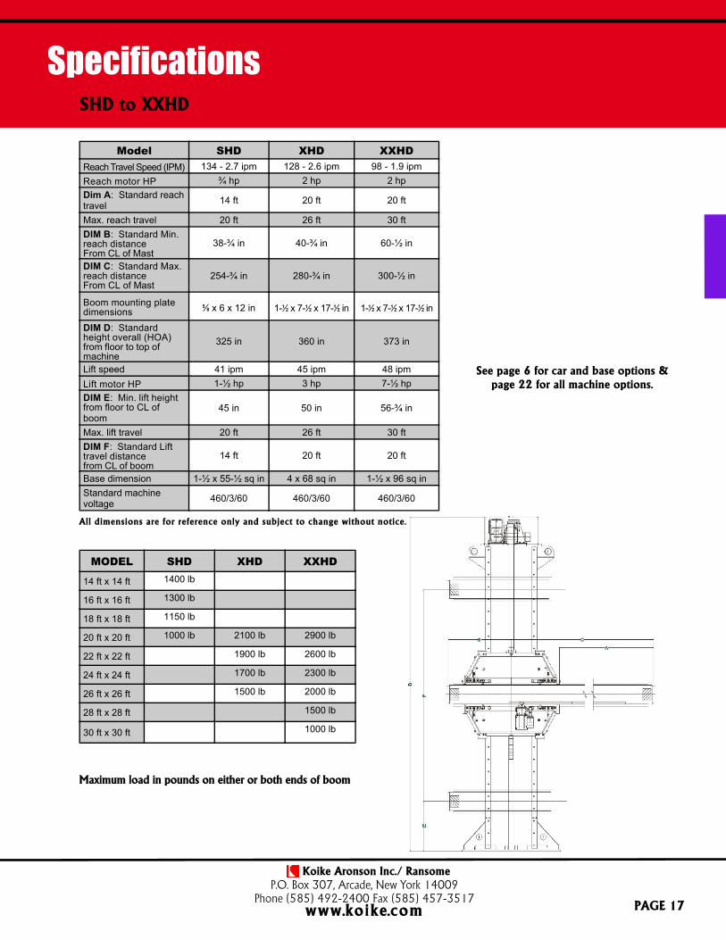
All dimensions are for reference only and subject to change without notice.
MODEL SHD XHD XXHD
14 ft x 14 ft 1400 lb
16 ft x 16 ft 1300 lb
18 ft x 18 ft 1150 lb
20 ft x 20 ft 1000 lb 2100 lb 2900 lb
22 ft x 22 ft 1900 lb 2600 lb
24 ft x 24 ft 1700 lb 2300 lb
26 ft x 26 ft 1500 lb 2000 lb
28 ft x 28 ft 1500 lb
30 ft x 30 ft 1000 lb
Maximum load in pounds on either or both ends of boom
Model SHD XHD XXHDReach Travel Speed (IPM) 134 - 2.7 ipm 128 - 2.6 ipm 98 - 1.9 ipmReach motor HP ¾ hp 2 hp 2 hpDim A: Standard reachtravel 14 ft 20 ft 20 ft
Max. reach travel 20 ft 26 ft 30 ftDIM B: Standard Min.reach distanceFrom CL of Mast
38-¾ in 40-¾ in 60-½ in
DIM C: Standard Max.reach distanceFrom CL of Mast
254-¾ in 280-¾ in 300-½ in
Boom mounting platedimensions
5⁄8 x 6 x 12 in 1-1⁄2 x 7-1⁄2 x 17-1⁄2 in 1-1⁄2 x 7-1⁄2 x 17-1⁄2 in
DIM D: Standardheight overall (HOA)from floor to top ofmachine
325 in 360 in 373 in
Lift speed 41 ipm 45 ipm 48 ipmLift motor HP 1-½ hp 3 hp 7-½ hpDIM E: Min. lift heightfrom floor to CL ofboom
45 in 50 in 56-¾ in
Max. lift travel 20 ft 26 ft 30 ftDIM F: Standard Lifttravel distancefrom CL of boom
14 ft 20 ft 20 ft
Base dimension 1-½ x 55-½ sq in 4 x 68 sq in 1-½ x 96 sq inStandard machinevoltage 460/3/60 460/3/60 460/3/60
See page 6 for car and base options &page 22 for all machine options.

KOIKE ARONSON, INC. / RANSOME
LSSeriesSeam Welders
The fixed height mandrel is incorporated into the machine basewith provision to attach gas purge and water cooling capability ifnecessary, water cooling requires an in-house water supply or waterchiller with pump. A replaceable copper backing bar is attached tothe top of the mandrel. Retractable alignment mechanisms areprovided for aligning the plate.
Machine equipped with aluminum clamping fingers for maximumconduction of heat away from weld and to prevent arc blow causedby magnetization of the ram (optional replaceable copper tippedfingers tips are available). A stainless steel pressure support plate isprovided at the loading end of the machine to guard againstmachine magnetization.
Full-length precision custom side beam runs the full length ofthe machine. Side beam assembly is adjustable for aligning andleveling with mandrel and weld joint. The travel carriage is a rackand pinion design to provide positive travel. A cable carrier withsupporting shelf is provided on rear of side beam to support andcapture incoming cables and hoses to welding head.
Carriage over-travel limit switches and adjustable weld lengthlimit switches are standard. The side beam with rack and piniondriven carriage and optional welding equipment can be arranged toallow for specified travel lengths.
Machine is freestanding and all controls are built into rear frame.Nema 4/12 enclosure, with circuit breakers. A remote pendantcontrol is provided for operator convenience with 1-turnpotentiometer, start/stop, forward/reverse, and auto/manual selectorswitch. Operation of pressure finger banks is individual andcontrolled by foot treadle. A microprocessor is used to controlmany welding wire functions, including speed control, start/stopdelays, and wire retract distance. Standard controls include airpressure regulator. Primary voltage: 115/1/60
PAGE 18
Internal, External and Flat Plate Models
Features
▪ Rack and pinion poweredcarriage
▪ Optional Copper tipped holddown fingers
▪ Water cooled back-up bar
▪ Gas purge back-up bar
▪ Standard plate thickness upto 3/8 inch
▪ Welding equipment can beprovided or customersupplied

Koike Aronson Inc./ RansomeP.O. Box 307, Arcade, New York 14009
Phone (585) 492-2400 Fax (585) 457-3517www.koike.com
SpecificationsLongitudinal Seam Welders
All dimensions are for reference only and subject to change without notice.
PAGE 19
Model LS-48 LS-60 LS-72 LS-96 LS-120 LS-144
Effective weld seam length 48 in 60 in 72 in 96 in 120 in 144 in
Maximum plate thickness 3⁄8 in 3⁄8 in 3⁄8 in 3⁄8 in 3⁄8 in 3⁄8 in
Mandrel diameter 4 in 5 in 6 in 6 in 8 in 10 in
Minimum part diameter 4-½ in 5-½ in 6-½ in 6-½ in 8-½ in 10-½ in
Maximum part diameter 36 in 36 in 36 in 36 in 36 in 36 in
Standard working height 45 in 45 in 45 in 45 in 45 in 45 in
Shop air required 100 psi 100 psi 100 psi 100 psi 100 psi 100 psi
Standard voltage 115/1/60 115/1/60 115/1/60 115/1/60 115/1/60 115/1/60
Specifications shown for standard external longitudinal seamers.Please consult factory for internal, flat plate or any other special requirements.

KOIKE ARONSON, INC. / RANSOME
SBFeatures
Series
Koike Aronson/Ransome manufactures a wide variety ofside beam designs and configurations. Both fixed height andelevating models can be utilized to fit your specific application.Manual and powered carriages provide great versatility andallow the operator to have precise control over the weldingprocess.
All side beam welders are designed to meet thecustomers specific needs. Beam and travel length, number andstyle of carriages, and beam configuration are just a few of theavailable options for Koike’s side beam Positioner line.
Welding equipment can be completely provided,installed and integrated by Koike Aronson Inc. or the customercan order the side beam carriages with blank carriage plates toinstall their existing equipment.
PAGE 20
Side Beams
Fixed, elevating and pantograph styles
▪ Elevating models available
▪ Controls for overlaystations
▪ Pantograph linkage styleoptional
▪ Powered and manualcarriages
Standard hand pendantprovided with all models

Koike Aronson Inc./ RansomeP.O. Box 307, Arcade, New York 14009
Phone (585) 492-2400 Fax (585) 457-3517www.koike.com
Side Beams
PAGE 21
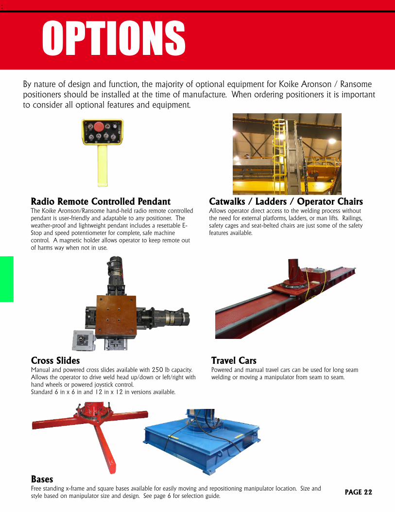
OPTIONSBy nature of design and function, the majority of optional equipment for Koike Aronson / Ransomepositioners should be installed at the time of manufacture. When ordering positioners it is importantto consider all optional features and equipment.
:
Radio Remote Controlled PendantThe Koike Aronson/Ransome hand-held radio remote controlledpendant is user-friendly and adaptable to any positioner. Theweather-proof and lightweight pendant includes a resettable E-Stop and speed potentiometer for complete, safe machinecontrol. A magnetic holder allows operator to keep remote outof harms way when not in use.
Catwalks / Ladders / Operator ChairsAllows operator direct access to the welding process withoutthe need for external platforms, ladders, or man lifts. Railings,safety cages and seat-belted chairs are just some of the safetyfeatures available.
Travel CarsPowered and manual travel cars can be used for long seamwelding or moving a manipulator from seam to seam.
PAGE 22
BasesFree standing x-frame and square bases available for easily moving and repositioning manipulator location. Size andstyle based on manipulator size and design. See page 6 for selection guide.
Cross SlidesManual and powered cross slides available with 250 lb capacity.Allows the operator to drive weld head up/down or left/right withhand wheels or powered joystick control.Standard 6 in x 6 in and 12 in x 12 in versions available.

180 Degree Head OrientatorAllows head to be manually positioned at 0 degrees,+90 degrees and –90 degrees to switch between girthand long seams, or weld direction without switchingflux pick-up and drop nozzle locations.
Wire Drum TurntablesAllows large drums of wire to be mounted to the rear of themachine boom. Conduit runs the length of boom to deliverwire to the welding head. Single and dual head versionsavailable.
Vision SystemsAllows operator to view weld through a remote mountedcamera system. This increases safety by keeping operator atfloor level and increases quality. Standard SAW and open arcversions are available.
PAGE 23
OPTIONS:
Welding EquipmentMultiple configurations and manufacturers can be custommounted and integrated to a welding manipulator. Controlscan be mounted to customer specifications which willprovide the best access for the operator by improvingvisibility and safety.
Cable ManagementOptional cable carriers for the lift and reach and caraxis is available. Welding leads, control and powercables can all be neatly run and protected. Enclosedand steel versions available upon request.
Seam TrackersTactile or laser guided weld seam trackers are an automatedmethod for accurately tracking the weld seam. Variousmodes allow for the tracking a many different joint designsand situations.

IPM Meters and DisplaysIPM travel speeds can be displayed or programmed with varioustypes of displays or a touch screen HMI.
Equipment Tower/Mounting PlatformsMast mounted power sources and flux recovery systems, rotatewith mast to avoid cable wind up and provide ease in cablerouting.
OPTIONS
Special Designed Welding HeadsSmall diameter, 90 degrees and other specially designed weldingheads for specific customer solutions.
Variable Speed Lift AxisOptional variable speed lift allows the operator to vary the speedof the lift axis. Please specify the speed range required whenordering.
PAGE 24
:
Operator stands and controlsFloor mounted integrated controls for manipulator and all optionsin one stand for operator convenience.
Powered Mast RotationProvides powered mast rotation allowing the operator to swingthe boom out of the work area or work between two stationswith one manipulator.

How to Order/Request a Quote
Contact your local distributor To find your local distributor, please visit
www.koike.com/distributor-locator
Contact a Manufacturers’ Sales Representative To find a representative nearest to you, please visit www.koike.com/find-a-sales-rep
Contact our Positioner Sales Business Unit Call toll-free: (800) 252-5232, ext. 480 International: (585) 492-2400 Email: [email protected] Submit a form via our website @ www.koike.com/welding-machine-contact-form
Thank you for your interest in Koike Aronson, Inc. /Ransome,we look forward to helping you build your business!

NOTES

NOTES

WELDING MANIPULATORS 12/17 KENG
Koike Aronson, Inc./Ransome
635 W. Main StreetP.O. Box 307
Arcade, NY 14009
Phone: (585) 492-2400Fax: (585) 457-3517
Toll Free: (800) 252-5232
www.koike.com
Koike Aronson Brasil
Rua Agostinho Mazza N° 31Bairro Parque do Trevo
Jaboticabal - SPCEP 14871-710
Tel/Fax: (16) 3202-8439
www.koike.com/br


