ARONSON TECHNICAL MANUAL KOIKE ARONSON, INC. 635 W. Main St., Arcade NY, 14009-0307(585) 492 2400, Fax (585) 457 3517 Visit us at www.koike.com MONOGRAPH MILLENNIUM /CUTTER II INSTRUCTION MANUAL MI0556A Subject to Change Without Notice November 26, 2008 REV. D
Transcript
ARONSON TECHNICAL MANUAL
KOIKE ARONSON, INC.635 W. Main St., Arcade NY, 14009-0307(585) 492 2400, Fax (585) 457 3517
Visit us at www.koike.com
MONOGRAPH MILLENNIUM /CUTTER II
INSTRUCTION MANUAL MI0556ASubject to Change Without Notice
November 26, 2008REV. D
CONTENTS
MONOGRAPH MILLENNIUM/CUTTER II
SECTION 1 SAFETY PRECAUTIONS
Section 1.1 General Safety........................................................................... 4Section 1.2 General Safety, Plasma Cutting................................................. 5Section 1.3 General, Miscellaneous ............................................................. 7Section 1.4 Work Area Layout ..................................................................... 9
Appendix A List of Terms and Abbreviations ..............................................A1Appendix F Plasma Operation .................................................................... F1Appendix L PHC Operation and Set Up Guide ........................................... L1
Safety
1
SECTION 1SAFETY PRECAUTIONS
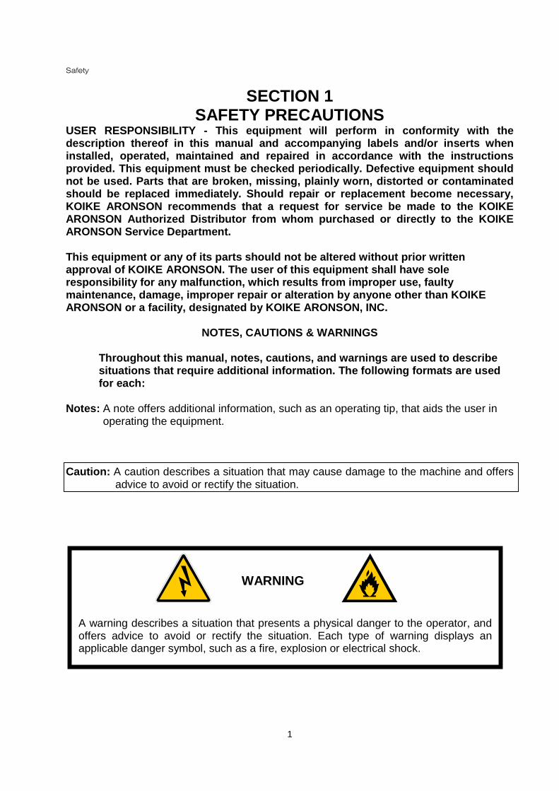
USER RESPONSIBILITY - This equipment will perform in conformity with thedescription thereof in this manual and accompanying labels and/or inserts wheninstalled, operated, maintained and repaired in accordance with the instructionsprovided. This equipment must be checked periodically. Defective equipment shouldnot be used. Parts that are broken, missing, plainly worn, distorted or contaminatedshould be replaced immediately. Should repair or replacement become necessary,KOIKE ARONSON recommends that a request for service be made to the KOIKEARONSON Authorized Distributor from whom purchased or directly to the KOIKEARONSON Service Department.
This equipment or any of its parts should not be altered without prior writtenapproval of KOIKE ARONSON. The user of this equipment shall have soleresponsibility for any malfunction, which results from improper use, faultymaintenance, damage, improper repair or alteration by anyone other than KOIKEARONSON or a facility, designated by KOIKE ARONSON, INC.
NOTES, CAUTIONS & WARNINGS
Throughout this manual, notes, cautions, and warnings are used to describesituations that require additional information. The following formats are usedfor each:
Notes: A note offers additional information, such as an operating tip, that aids the user inoperating the equipment.
Caution: A caution describes a situation that may cause damage to the machine and offersadvice to avoid or rectify the situation.
A warning describes a situation that presents a physical danger to the operator, andoffers advice to avoid or rectify the situation. Each type of warning displays anapplicable danger symbol, such as a fire, explosion or electrical shock.
WARNING
Safety
2
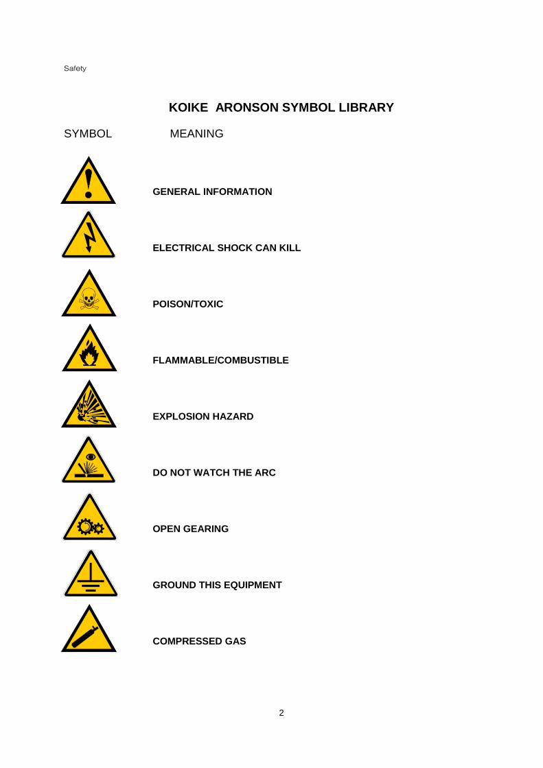
KOIKE ARONSON SYMBOL LIBRARY
SYMBOL MEANING
GENERAL INFORMATION
ELECTRICAL SHOCK CAN KILL
POISON/TOXIC
FLAMMABLE/COMBUSTIBLE
EXPLOSION HAZARD
DO NOT WATCH THE ARC
OPEN GEARING
GROUND THIS EQUIPMENT
COMPRESSED GAS
Safety
3
SYMBOL MEANING
EYE PROTECTION REQUIRED
USE AN APPROVED RESPIRATOR
WEAR APPROVED EAR PROTECTION
INSULATED GLOVES REQUIRED
INSULATED FOOTWARE REQUIRED
NO OPEN FLAME
HOT SURFACE DO NOT TOUCH
DO NOT REMOVE GUARDS
WEAR PROPER EYE PROTECTION WHEN PLASMA CUTTING
WEAR PROTECTIVE CLOTHING
Safety
4
1.1 GENERAL SAFETY
Operation of this machine involves variousmoving and rotating parts that could proveto be dangerous. Follow the precautions inthis General Safety Section, as well asthose throughout this manual, for yourpersonal safety and the safety of people inthe area that may be affected. Failure toobserve these safety practices may causeserious injury or death.
1. Install and operate this machine only ina well-ventilated area.
2. Connect and maintain electrical groundsto the equipment according to localcodes and the National Electrical Code.
3. Check gas and electrical connections fortightness after installation and on aregular basis thereafter.
4. Keep combustibles away from the workarea or protect them from sparks andflames.
5. Never use oxygen to ventilate the areaor clean off clothing.
6. Replace hoses that are damaged byphysical abuse or by sparks, heat oropen flame.
7. Examine hoses at regular intervals forleaks, wear, loose connections or otherhazards.
8. Coil excess hose and place it out of theway to prevent damage and to eliminatetripping danger.
9. Maintain all pressure regulators in properworking condition.
10. Wear filter-lens safety eye protection.Wear gauntlet gloves, safety shoes,flame-retardant clothing, and no-cufftrousers. Do not wear loose clothingaround this machinery as they can catchon the machine.
11. Shut off power and air supplieswhenever leaving the machineunattended or before servicing.
12. Keep equipment clean and in goodoperating condition.
13. Read accessory instruction manualssupplied for these items for additionalsafety and operating guidelines beforeoperating this equipment.
14. No repair should ever be undertaken orattempted by anyone other than aKOIKE ARONSON designatedtechnician.
Before using this equipment and its options each person operating, maintaining orsupervising the use of this equipment must read the following safety instructions.
Safety
5
15. Read and understand further detailedsafety precautions throughout thismanual.
1.2 GENERAL SAFETY, PLASMACUTTING
Plasma Arc cutting is a high intensitysource of visible light emission as well asultraviolet and infrared radiation. It cancause severe eye damage and inflict burnson exposed skin when those portions of thebody are not suitably protected. Follow theprecautions in this General Safety Sectionand read the supplied plasma equipmentinstruction manual for additional and moredetailed safety precautions.
1. Facilities should be available for themedical treatment of arc flashes orburns to the eyes.
2. Provide radiation protection for theoperator and for personnel in theadjacent area.
3. Do not, under any circumstances, lookat a plasma arc without full eyeprotection. When near plasma cuttingequipment always wear flash goggleswith side shields and containing No. 4filter lenses.
4. The operator must use in addition toflash goggles, a suitable helmet for eyeand face protection when cutting. Thehelmet must be equipped with a numberfilter plate as indicated:
Arc Current US Shade No. ISO 4850Up to 100 Amps 8 11100 to 200 Amps 10 11-12200 to 400 Amps 12 13Over 400 Amps 14 14
5. Do not use helmet or hand shields thatare not in good condition. Repair orreplace promptly. Protect colored filterplates with a clear glass cover plate.
6. Warn other people in the area not to lookdirectly at the arc unless they wearglasses/goggles or a helmet.
7. Never, start the plasma arc withoutdetermining that nearby personnel arewearing adequate protective equipment.
8. All areas of the body must be covered by
dark substantial clothing (preferablyflame retardant) to protect against arcburn, sparks and flying hot metal.
9. The plasma operation should be locatedin an area where protection for otherpersonal may be readily provided.Portable non-combustible reflectingscreens or enclosures with non-reflectingwalls may be used. Screens andenclosures should permit free circulationof air at floor level.
10. Do not cut in the presence ofatmospheres containing even minuteamounts of chlorinated solvents such asTrichloroethylene andPerchloroethylene since the heat andultraviolet radiation can decomposethese vapors to form Phosgene, a highlytoxic gas, and other irritatingdecomposition products.
11. Do not cut in atmospheres containingexplosive dust or vapors.
Safety
6
12. Keep the cutting area well ventilated.
13. Wear proper breathing mask whencutting galvanized metal and useproper ventilation.
14. Do not cut pressurized cylinders or anyclosed container.
15. Make fire extinguishers available in thecutting area.
16. Remove combustible material from theimmediate cutting area.
17. Quench freshly cut metal or allow metalto cool before handling it or bringing itin contact with combustible materials.
18. To prevent electric shock keep yourbody and clothing dry.
19. Do not stand in, sit on or lie on any wetsurface when using the plasma system.
20. Maintain proper insulation againstelectrical shock. If you must work in ornear a damp area, use extreme
caution. Wear insulated gloves andboots.
21. Provide a wall mounted disconnectswitch with proper size fuses close tothe power supply. This switch allows theoperator to turn the power supply offquickly in an emergency situation.
22. Conform to all local codes for primarywiring sizes and types.
23. Inspect the primary power cordfrequently for damage or cracking of thecover. Bare wiring can kill. Do not usethe system with a damaged power cord.If a power cord is damaged, replace itimmediately.
24. Inspect the torch leads. Replace if frayedor damaged.
25. Never operate the plasma system unlessthe power supply unit covers are inplace. Exposed power supplyconnections present a severe electricalhazard.
26. Do not pick up the work piece, includingthe waste cutoff, while you cut. Leavethe work-piece in place or on theworktable with the work cable attachedat all times.
27. Before changing the torch parts,disconnect the main power supply. Afterchanging the torch parts and returningthe retaining cap to its operatingposition, plug the power supply in again.
28. Never, bypass or shortcut the safetyinterlocks.
29. Before removing a power supply coverfor maintenance use approved lockoutprocedures, disconnect the main powerat the wall, shut off switch or unplug thepower supply. To avoid exposure tosevere electrical hazard, wait five (5)
Safety
7
minutes after disconnecting the mainpower to allow capacitor discharge tooccur. Test for zero volts.
30. Be sure the power cord is plugged intoa properly grounded outlet or that thepower cord ground wire is properlyconnected to the ground in thedisconnect box.
31. If installation of the plasma systeminvolves connecting the power cord tothe power supply, ensure that thepower cord ground wire is properlyconnected. Conform to CSA standardsby placing the power cord ground wireon the stud first; then place the otherground wires on top of the power cordground. Fasten the retaining nut tightly.
32. Make sure that all electrical connectionsare tight to avoid excessive heating.
33. Clamp the work cable with good metal-to-metal contact to the work-piece (notthe portion that will fall away) or to theworktable.
34. Connect the worktable to a good earthground. Consult the National ElectricalCode, Grounding Electrode System, orother appropriate national or localcodes.
35. Plasma cutting operation noise levelsmay be high enough to require earprotection for the operator and otherpersonnel in the adjacent area.
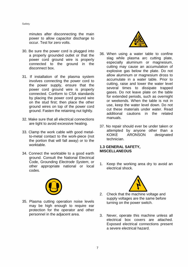
36. When using a water table to confineslag while plasma arc cutting plate,especially aluminum or magnesium,cutting may cause an accumulation ofexplosive gas below the plate. Do notallow aluminum or magnesium dross toaccumulate in a water table. Prior tocutting, raise and lower the water levelseveral times to dissipate trappedgases. Do not leave plate on the tablefor extended periods, such as overnightor weekends. When the table is not inuse, keep the water level down. Do notcut these materials under water. Readadditional cautions in the relatedmanuals.
37. No repair should ever be under taken orattempted by anyone other than aKOIKE ARONSON designatedtechnician.
1.3 GENERAL SAFETY,MISCELLANEOUS
1. Keep the working area dry to avoid anelectrical shock.
2. Check that the machine voltage andsupply voltages are the same beforeturning on the power switch.
3. Never, operate this machine unless allelectrical box covers are attached.Exposed electrical connections presenta severe electrical hazard.
Safety
8
4. When replacing or cleaning a torch tipduring cutting be sure to give the tipsufficient time to cool. The tip will bevery hot.
5. After cutting never touch the work-pieceor scrap until they cool. You can beburned.
6. During the piercing operation of heavierplate, (25mm or larger) there can be agood deal of spatter. Be sure to stayaway from the torch and stay in theoperation zone to prevent exposure toburn from the spatter.
7. During the cutting operation never touchthe plasma arc.
8. Do not climb on the cutting table, as it ispossible to slip and cause injury.
9. Take care not to climb on or over the railas it has rack attached to it and cancause injury.
WARNING
Protect yourself and others. Read and understand these instructions. FUMES ANDGASES can be dangerous to your health. HEAT RAYS (INFRARED &ULTRAVIOLET) from flame, arc or hot metal can injure eyes. Read and understandthe manufacturers’ instructions and your employer's safety practices. Use enoughventilation/exhaust at the flame/arc, or both, to keep fumes and gases from yourbreathing zone, and the general area. Keep your head out of the fumes.
Safety
9
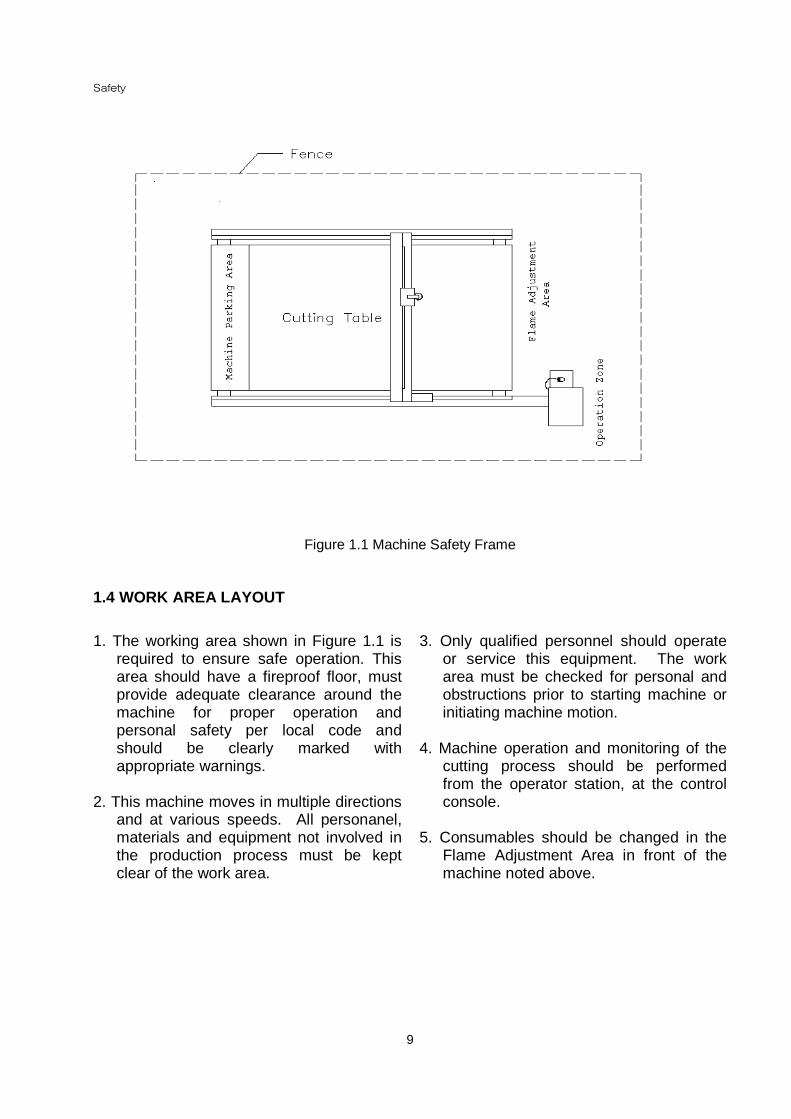
Figure 1.1 Machine Safety Frame
1.4 WORK AREA LAYOUT
1. The working area shown in Figure 1.1 isrequired to ensure safe operation. Thisarea should have a fireproof floor, mustprovide adequate clearance around themachine for proper operation andpersonal safety per local code andshould be clearly marked withappropriate warnings.
2. This machine moves in multiple directionsand at various speeds. All personanel,materials and equipment not involved inthe production process must be keptclear of the work area.
3. Only qualified personnel should operateor service this equipment. The workarea must be checked for personal andobstructions prior to starting machine orinitiating machine motion.
4. Machine operation and monitoring of thecutting process should be performedfrom the operator station, at the controlconsole.
5. Consumables should be changed in theFlame Adjustment Area in front of themachine noted above.
General Introduction
10
SECTION 2GENERAL INTRODUCTION
2.1 SCOPE
This manual provides general installation,operation and service information for theKOIKE ARONSON MONOGRAPHMILLENNIUM/CUTTER II series of cuttingmachines. This manual includes an illustratedpart listing to aid in ordering parts.
2.2 DESCRIPTION
Your MONOGRAPH MILLENNIUM/CUTTER IISeries is designed with time provenconstruction techniques. This machine usesthe latest in electronic and mechanicaltechnologies. Speed, accuracy, versatility anddurability have been engineered into theMILLENNIUM for demanding production jobs.The CNC programmable control allows forease of operation and precision cutting of platesteel. In addition, accessories for specificpurposes are available to further enhance theversatility of the MONOGRAPHMILLENNIUM/CUTTER II.
The Koike Aronson Inc. MONOGRAPHMILLENNIUM/CUTTER II is designed to meetyour cutting requirements of steel plate.
The MONOGRAPH MILLENNIUM incorporatestwo 1.2KW AC servo drive systems into its dualprocessor controlled KARCNC. The CNC isequipped with torch control for one plasmasystem.
2.3 AXIS DEFINITION
To avoid confusion in determining direction andaid in identifying part locations:
1. The X-axis is parallel to the transverse(main) beam.
2. The Y-axis is parallel to the longitudinal railsystem.
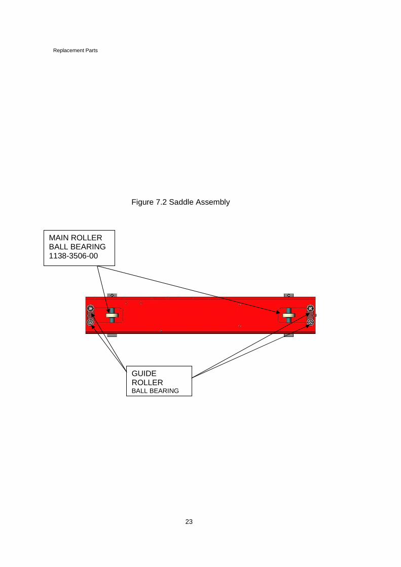
2.4 SADDLE ASSEMBLY
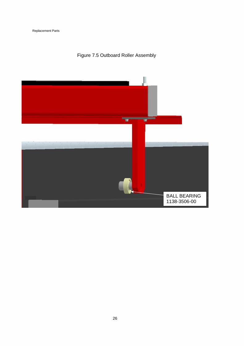
One saddle assembly, located on the operatorscontrol side of the machine, travels on the Y-axis rail system driven by a Y-axis drive motorand planetary gearbox assembly mounted onthe outboard side of the carriage. Two (2) wheelassemblies support the saddle, one on theforward end and one on the aft end of thesaddle to provide stability. The saddle utilizestwo sets of rollers to provide guidance down therail system. The inboard roller, facing the frontof the machine, is essential to adjust to theguide rail and maintain positive machinealignment. A single roller for simplicity supportsthe opposing end of the transverse beamassembly and rides on the Y-axis rail system.
2.5 TRANSVERSE BEAM ASSEMBLY(X-drive)
The beam assembly consists of structuraltubing extending in a left to right direction facingthe machine and supported by the saddle androller assemblies. The beam is factory squaredto both assemblies, pinned in position andbolted.
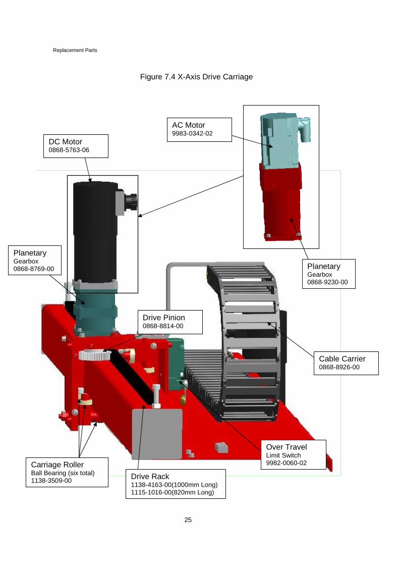
2.6 X-AXIS DRIVE ASSEMBLY
The X-axis drive carriage supports one plasmatorch station. The drive is located on thetransverse beam carriage. A motor andplanetary gear assembly drives the carriagealong the X-axis. The X-axis pinion engages toa rack assembly mounted to the transversebeam to provide precise motion.
General Introduction
11
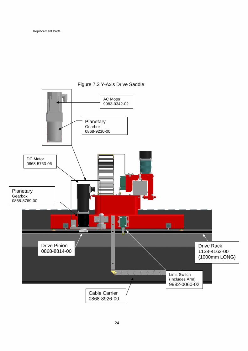
2.7 Y-AXIS DRIVE ASSEMBLY
The Y-axis drive assembly is mounted in thecenter of the saddle assembly facing out. Apivot mount assembly supports the motor andplanetary gear unit.
2.8 OPERATOR CONTROL CONSOLE
The operator control console is mounteddirectly to the end of the rail on the left frontcorner of the machine. This offers a good viewof the work piece and keeps the operator asafe distance from the transverse beamassembly.
2.9 LIMIT SWITCHES
Two (2) limit switches are mounted on thetransverse beam assembly. The limit switchesprevents an over-travel condition of the X-axisdrive unit. A limit switch mounted to the saddlelimits Y-axis travel. Should a limit switch betripped, the drive signal is interrupted, and allcutting operations are stopped. To recover froma limit trip see the operation section of thismanual.
2.10 ELECTRICAL FEATURES
The MONOGRAPH MILLENNIUM SERIESKARCNCtm incorporates dual microprocessorarchitecture for true muti-tasking. Oneprocessor is dedicated for motion control, whilethe other is dedicated to Windows functionality.Two AC brushless servo systems capable ofdelivering 1.2 KW of power are incorporatedinto the CNC.
General Introduction
12
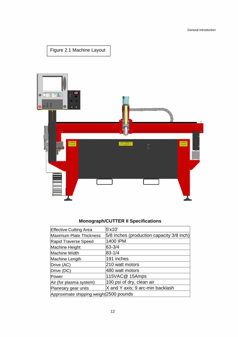
Monograph/CUTTER II Specifications
Effective Cutting Area 5'x10'
Maximum Plate Thickness 5/8 inches (production capacity 3/8 inch)
Rapid Traverse Speed 1400 IPM
Machine Height 63-3/4
Machine Width 83-1/4
Machine Length 191 inches
Drive (AC) 210 watt motors
Drive (DC) 480 watt motors
Power 115VAC@ 15Amps
Air (for plasma system) 100 psi of dry, clean air
Planetary gear units X and Y axis; 9 arc-min backlash
Approximate shipping weight2500 pounds
Figure 2.1 Machine Layout
Pre-Installation Requirement
13
SECTION 3PRE-INSTALLATION REQUIREMENTS
3.1 PRE-INSTALLATION SAFETY
All equipment must be installed inaccordance with local requirements and theNational Electrical Code. Connect andmaintain good electrical grounds, as perarticle 250 of the NEC, to the supply groundwire, cutting machine and cutting table. Donot ground to electrical conduit, or pipescarrying gases or flammable liquids. Useonly correct sizes of electrical cable.
Plan to provide ventilation. Proper ventilationis vital for safety, good visibility and personalcomfort.
Equipment necessary for lifting the machineweight must be available at the time ofinstallation, for example, an overhead crane,forklift, and so forth.
All normal safety precautions used inworking with flammable gases, electricalequipment and heavy machinery, as well asprocedures listed in your company safetymanual, must be followed to preventpossible injury.
CAUTIONWhen welding, DO NOT ground to themachine, the rail system or the burningtable, to avoid damage to electroniccomponents. Evidence of welding to thecutting machine equipment will void allwarranties.
NOTE: The following preparations shouldbe complete before the arrival of theinstalling technician.
3.2 SITE LOCATION
The machine requires a space where floorvibration is at a minimum. Precisionoperation is necessary for accurate partprocessing. Avoid areas where vibrationscaused by drop hammers, heavymachinery and punch presses are used.Position the unit close to the productionline, with adequate lighting and ventilation.
Special consideration must be used in theselection of a site for machine operation.Gas supply, electrical power, clean dryshop air and water in the immediate vicinityare essential for economical operation ofthe machine. Material handling is importantfor safe loading and unloading of the parts.
3.3 SITE PREPARATION
This machine should only be installedindoors on a clean dry surface.
Solid, secure and accurate machineinstallation is critical to insure maximumaccuracy for the cutting plasma machine.The floor for the machine installation thefloor should be level within 9.5mm (3/8”)over the entire length and width. The floorarea supporting the machine should bespecified by a contractor and be free fromcracks or other imperfections.
If a possibility of equipment vibrationexists, the machine should be providedwith an adequate isolation pad.
Pre-Installation Requirement
14
3.4 ELECTRICAL REQUIREMENTS
The position of cables is very important forproper operation of the system. Use carewhen routing electrical wires and cables toavoid pinching or chafing against metallic orother abrasive objects.
Local codes as well as the NationalElectrical Standard must be followed for allpower and grounding installations.
Cutting machine electrical requirements are115 Volts AC (±10%), 50-60 Hz, singlephase, 20 Amps. Koike Aronson providesthe machine main power cable. KoikeAronson recommends all power cables bekept as far as possible from auxiliarycomponents such as machine control boxesand solenoids. Avoid random placement ofwiring.Keep all wiring as short as possible, DONOT COIL ANY CABLES. Make sure allsupply hoses and cables are long enoughfor the type of carrier system used.
The machine requires careful and properinstallation of ground rods with associatedwire connections. Ground wires will connectto a mono-post ground connection. Groundrod size for plasma systems of 100 amperesor less should be 1/2in. (12mm) diametersolid copper, 8ft. (2.5M) in length. The wireconnection to the Star ground should be aproper sized stranded wire, and should not
exceed 4ft. (1.2M) in length. The groundrod for machines with a plasma system of100 amperes or more should be 3/4in.(19mm) diameter solid copper, 14ft. (4.5M)in length. If you cannot drive a 14ft. (4.5M)ground rod you may use two (2) 8ft. (2.5M)ground rods connected to each other with4/0 cable and then to the Star ground. Thewire to the Star ground connection will be aminimum of 4/0 cable and should notexceed 4ft. (1.2M) in length.
Note: Ground rods must be installedaccording to the National ElectricalCode Standards.
All ground connections must make intimatecontact with the components they aregrounding. All rusted or painted surfacesmust be cleaned and the connectionsmade should be tight. Any grounding strapshould be sized to current load per article250 of the NEC.
3.5 COMPRESSED AIR
Compressed air for general blow down andclean up should be dry, clean and oil freewith a 5-micron maximum particle size.
CAUTIONThe AC power to the cutting machinemust come from a dedicated source. Noother machinery or equipment should beconnected to this line.
CAUTIONProper grounding of the cutting machineand peripheral equipment is critical forreliable and safe operation of thesystem.
Pre-Installation Requirement
15
Figure 3.1 General GroundLayout
15
Installation
16
SECTION 4INSTALLATION
4.1 INSTALLATION SAFETYPRECAUTION
Connect and maintain suitable electricalgrounds to the supply ground wire. Do notconnect ground to electrical conduit or to pipescarrying gases or flammable liquids. Use onlythe recommended size of electrical cable, inaccordance with article 250 of the NEC.
If it was necessary to install forced ventilation,operate the cutting machine only when suchventilation is running to prevent harmful anddangerous accumulations of fumes.
Avoid enclosing areas where fuel gas leaksmay occur, or insure that such leaks cannotoccur in lines passing through or ending inconfined spaces.
Use normal precautions when loading oroperating heavy equipment. Follow theprocedures in your company safety manual.
4.2 HANDLING AND STORAGE
When the shipment arrives at your location,accompany the driver in counting all thecartons indicated on the driver's waybill.
Inspect each piece for signs of mishandling orapparent damage. If discrepancies exist or anyevidence of damage exists, note it BOLDLY
across the face of the waybill BEFORE YOUSIGN IT. Sign the waybill only after thisinspection. If you note discrepancies on thedelivery ticket, DO NOT open the cartons.
Call the freight carrier’s local office and askthat a claims investigator be sent as soon aspossible to verify the status of the shipment.Also, call your Koike Aronson representative.Try to arrange the meeting so that the claimsinvestigator and the representative will bepresent when the damage/shortage is verified.The freight carrier will supply you with thenecessary claims forms if required. Freightclaims are the receivers’ responsibility. Pleasefollow these instructions carefully; KoikeAronson and your distributor will support youfully in the unlikely event that a freight claim isnecessary.
Handle the packing cartons carefully, right sideup as marked. Store cartons in a dry locationuntil ready to install.
4.3 MACHINE INSTALLATION
Refer to Koike Aronson MONOGRAPH/CUTTER II Setup and training CD forcomplete installation instructions.
4.4 UNPACKING AND CLEANING
The equipment has been packaged to preventdamage in transit. Unpack carefully to preventaccidental damage by uncrating tools. Afteruncrating, examine the equipment for signs ofdamage, particularly to control knobs, switchesand electrical components. Report any damageto the freight carrier and Koike Aronsonimmediately.
Remove preservation coating from allunpainted surfaces, as components areneeded for installation, with WD-40®, LPS-1®
or mineral spirits.
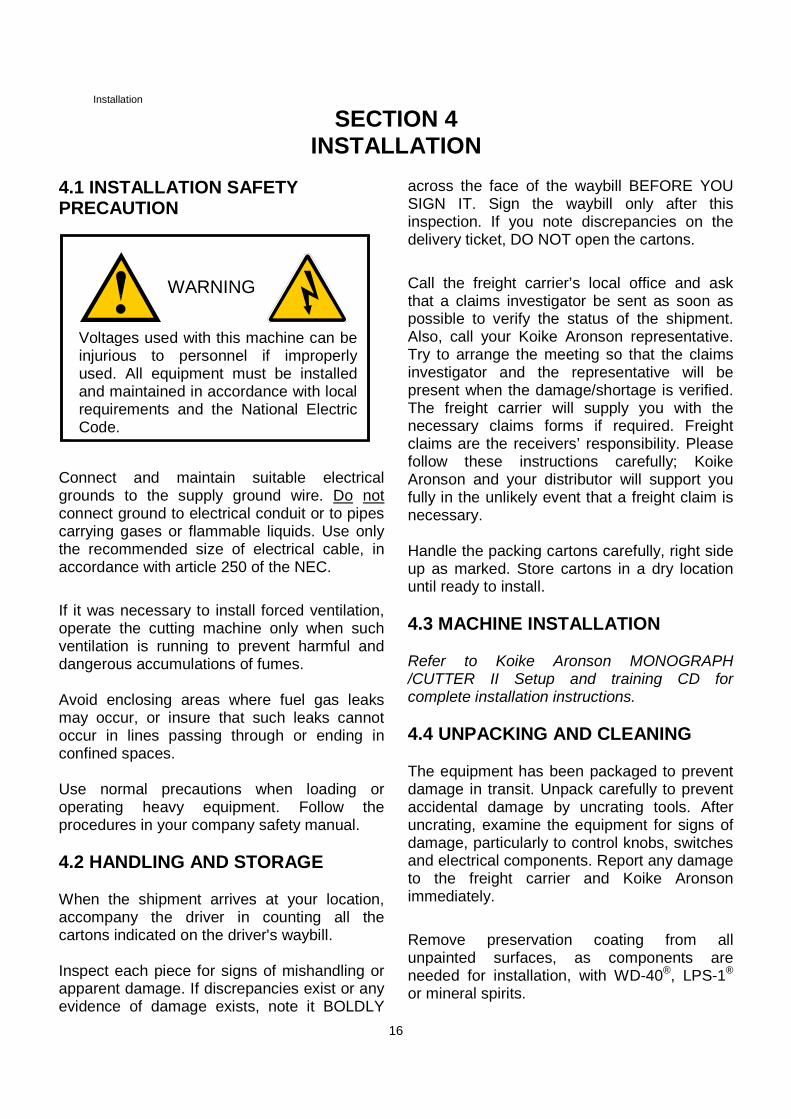
WARNING
Voltages used with this machine can beinjurious to personnel if improperlyused. All equipment must be installedand maintained in accordance with localrequirements and the National ElectricCode.
Installation
17
4.5 MACHINE LEVELING
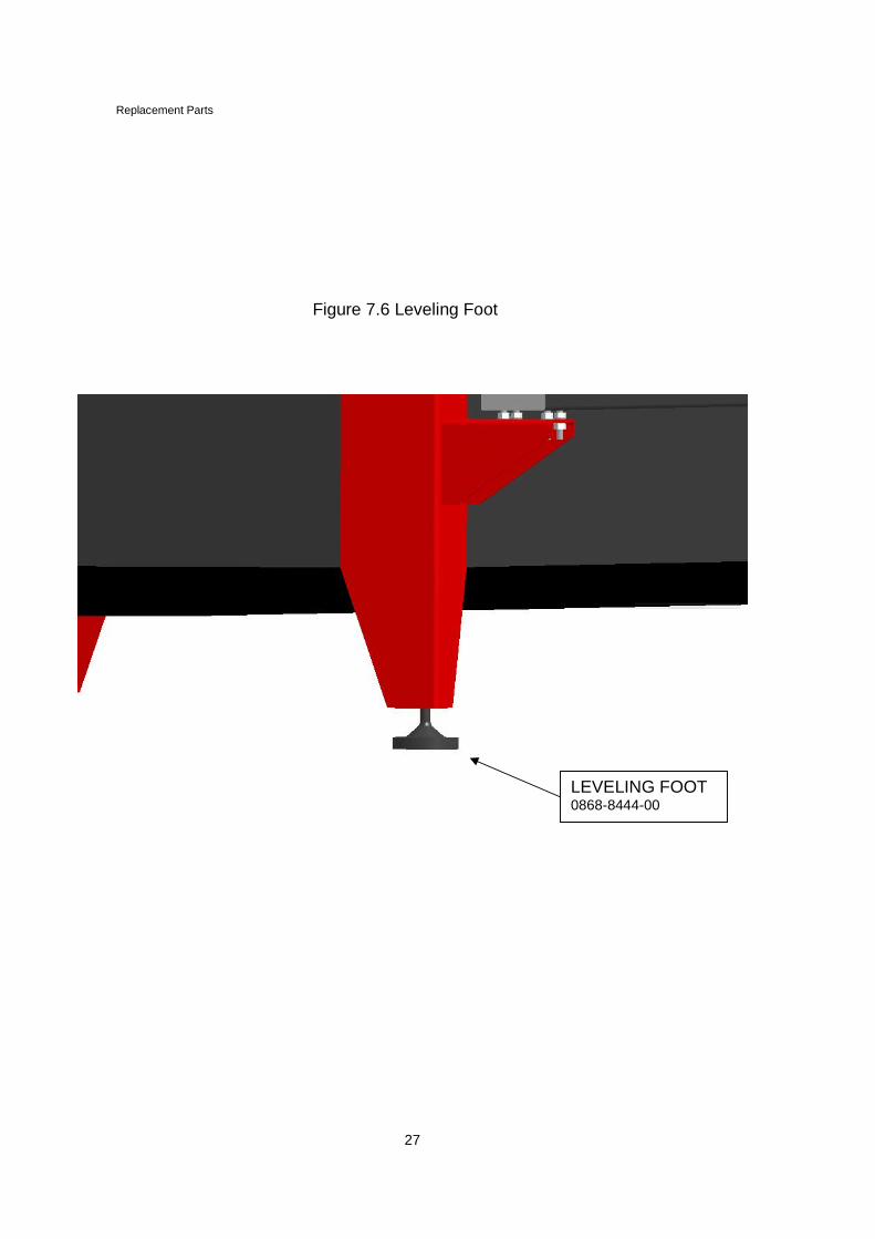
Once the machine is in place use thefour leveling feet to ensure that themachine is as close to level as possiblefor optimal cutting precision andperformance.
4.6 CNC INTERFACE
The CNC control has been removed from themachine for shipment. Unpack it CAREFULLYand install the CNC in the operator control.Connect the proper cable assembly to theCNC. All cable assemblies are labeled at KoikeAronson as to where they connect to the CNC.
4.7 UTILITIES
The machine is supplied with a flexible maincable carrier system. Route all supply hosesand cables through the carrier system in a neatand orderly fashion; using tie-wraps, tie eachcable and hose to the tie-plates located at eachend of the cable carrier.
Connect the power cable from a properly fuseddedicated source (review Section 3 Pre-Installation) to the power disconnect on themachine. Check to see that the power sourceis off and/or tagged Out of Service to avoid apotential electrical shock.
Connect the air hose to the main valve unitmarked “air”.
4.8 GENERAL PLASMA MACHINECONNECTIONS
Refer to the Koike Aronson MONOGRAPH/CUTTER II Setup and training CD forcomplete plasma machine installationinstructions.
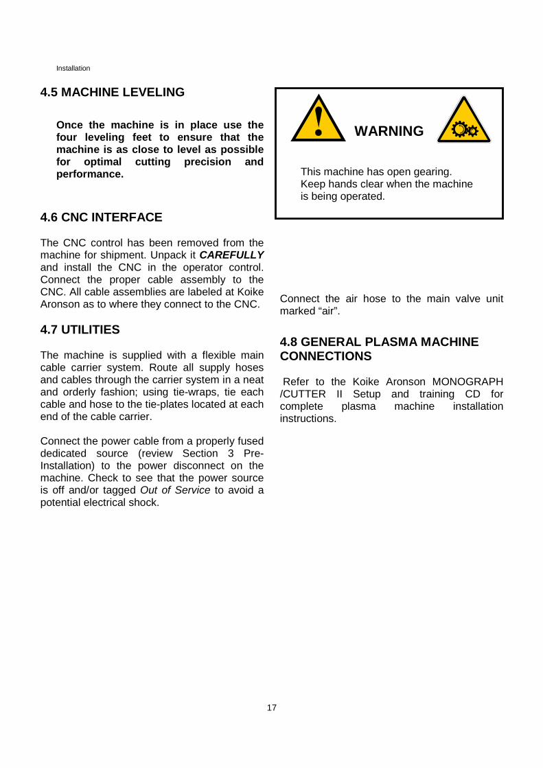
This machine has open gearing.Keep hands clear when the machineis being operated.
WARNING
Operationn MI0545A
18
SECTION 5 OPERATION
5.1 OPERATIONAL SAFETY
Follow the precautions in the SAFETY sectionand throughout this manual for your personalsafety and the safety of people near theequipment.
1. Operate cutting equipment only in a well-ventilated area.
2. Keep combustibles away from the workarea or protected from sparks and flames.
3. Wear appropriate eye protection safetygoggles with filter lens.
4. Keep equipment clean and in goodoperating condition.
5. WELDING: DO NOT ground to the machine,the rail system or to the cutting table at anytime to avoid damage to electroniccomponents. Failure to follow this warningmay void all manufacturers’ warranty.
5.2 GENERAL OPERATIONS
1. For machine control operations, refer tothe KARCNC Operation Manual.
Maintenance
19
SECTION 6MAINTENANCE
6.1 SAFETY PRECAUTIONS
1. Shut OFF main power switch, pull fuses, orlock and red tag switch before attemptingwork on electrical circuits. Do not touchelectrically CHARGED parts or those withresidual voltage, such as capacitors untilthey have been grounded and their electriccharge dissipated.
2. Keep power cables dry, free of oil andgrease, and protected at all times fromdamage by hot metal and sparks. DO NOTuse any power cable with worn or damagedinsulation, repair or replace immediately.
3. Equipment that is not functioning properlyshould NOT be used until all repairs havebeen completed and the equipment hasbeen tested to ascertain that it is in properoperating condition.
4. WELDING: DO NOT ground to the machine,the rail system, or to the cutting table at anytime to avoid damage to electroniccomponents. Failure to follow this warningmay void manufacturer's warranty.
5. Except for inspection and maintenance listedin this manual, it is recommended that anauthorized Koike Aronson, Inc. servicetechnician do all other servicing.
6. Goggles with correct filter lenses must beworn whenever torches are lit. Suitableprotective clothing must be worn wherenecessary.
Comply with these and other safety procedureslisted in this manual. Refer to appropriatemanuals, furnished by the manufacturer, forsafety procedures for plasma, drive, CNC orother optional equipment.
6.2 GENERAL INFORMATION
This manual provides standard preventativemaintenance procedures required for accurateand proper operation of theMONOGRAPH/CUTTER II cutting machine.Follow these procedures to maintain machineoperation at peak efficiency and to extend theuseful life of the machine.
The machine has been assembled, properlyadjusted and factory tested before shipment.Factory settings, other than those listed in theinstallation section of this manual, should notbe changed. If the machine performance isunsatisfactory, contact a Koike Aronson, Inc.authorized service representative for advice.
Keep the machine clean, in good condition andfree of oil, grease and other combustibles. Ifreplacement parts are required, it isrecommended that they be purchased fromKoike Aronson, Inc. through an authorizeddistributor.
The manufacturer for optional items such asplasma systems, microprocessor controls andcertain other components have furnishedseparate manuals listing maintenanceprocedures.
6.3 PREVENTATIVE MAINTENANCESCHEDULE
Although this machine does not require a greatdeal of maintenance, the following proceduresshould be preformed routinely based onoperation hours. The following maintenanceguidelines are solely the responsibility of theoperator (customer). Failure to comply withthese guidelines for your machine can result inpoor cut quality, a rough running machine orservice calls at the expense of the customerand are not covered under machine warrantyneither by the Distributor nor by KoikeAronson, Inc.
Maintenance
20
6.3.1 EACH EIGHT (8) OPERATIONHOURS
1. Blow off rails, rollers and wheels with low-pressure shop air (Not Oxygen).
2. Spray a clean cloth lightly with WD-40®orLPS-1®, and wipe the wheels, rollers,gears, rails and rack.
3. Ensure that the main saddle side guiderollers are tight to the side of the rail. Theoutside rollers are non-adjusting; the insiderollers are adjustable.
4. Clean plasma torch and tip.
6.3.2 EACH FIFTY (50) OPERATIONHOURS
1. Check for damage to the gear rack. Repairwith a file or replace if damage isexcessive.
2. Remove wheel guards located on theoutside of the saddles and clean mainwheels.
3. Clean and readjust the plasma torch holder.
4. Check roller bearings on X- axis carriagefor smooth operation. Clean and lube ifnecessary.
6.3.3 EACH TWO HUNDRED FIFTY(250) HOURS
Check for backlash in X and Y drive pinionsto the rack. Make sure the pinion is notworn. If backlash exists, check the rack forwear.
6.3.4 EACH ONE THOUSAND (1000)HOURS
Clean and dust off all electrical equipment.
6.4 GUIDE ROLLER ADJUSTMENT
After prolonged usage, the main saddleeccentric guide rollers may require adjustment.
Adjust eccentric bolts until rollers can just beturned, using thumb and forefinger, against theside of the rail. Check that all guide rollers turneasily as the machine is moved.
6.5 RAIL CLEANING
Spray a clean cloth lightly with WD-40®or LPS-1®, and wipe the top, sides and rack clean.When cutting splatter settles on the rails, cleanor chip off with a steel flat tool. Be sure not todamage the rail or rack.
File off larger burrs that may appear on therails as they could affect cutting performance.
6.6 ROLLER CLEANING
At least once each shift, remove dirt buildupfrom small rollers, main carriage side guiderollers and torch carriage rollers as follows:
a. Hold a steel flat bar (1.6 x 25 mm crosssection or a steel pocket rule) flat on railedge against roller surface.
b. Move the carriage in a direction away fromthe bar, holding the bar against the roller forat least one complete revolution to scrapeoff dirt build up.
6.7 WHEEL CLEANING
At least once each shift, remove dirt buildupfrom wheels on the Y-axis saddle.
Maintenance
21
Roll the carriage one wheel revolution scrapingoff buildup from the wheels with the edge of asteel flat bar (1.6 x 25 mm, or steel pocketrule).
6.8 GEARS AND PINIONS
At least each shift remove debris from gearsand pinions using a stiff wire brush. Spray on alight film of LPS-1®.
6.9 DRIVE TUNING PROCEDURE
The MONOGRAPH/CUTTER II uses AC servodrives. No electrical adjustments are required.The parameters for each drive are factory setand must not be changed without consultingKoike Aronson, Inc.
Replacement Parts
22
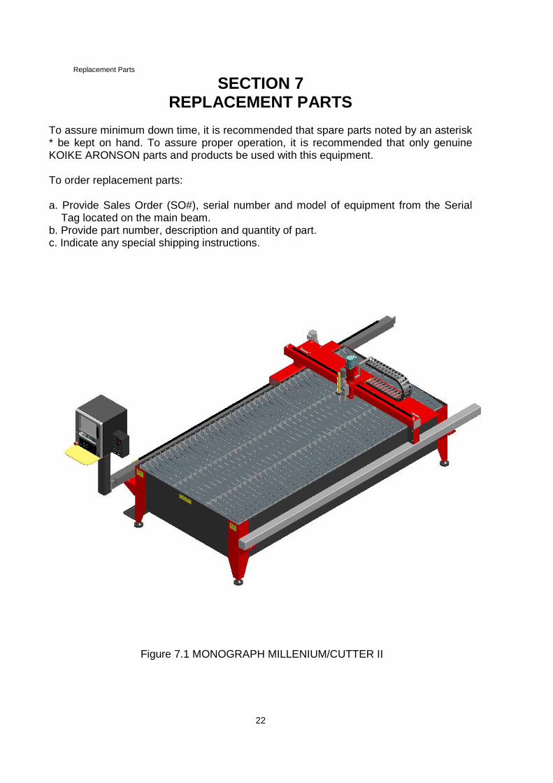
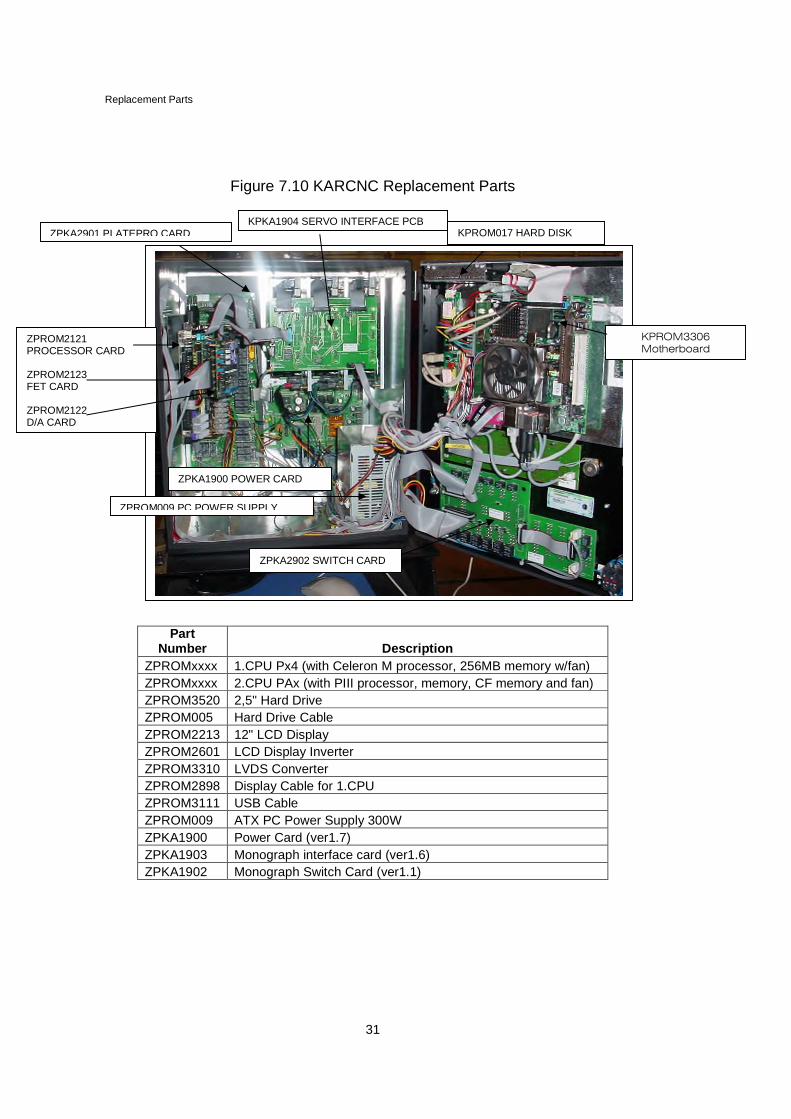
SECTION 7REPLACEMENT PARTS
To assure minimum down time, it is recommended that spare parts noted by an asterisk* be kept on hand. To assure proper operation, it is recommended that only genuineKOIKE ARONSON parts and products be used with this equipment.
To order replacement parts:
a. Provide Sales Order (SO#), serial number and model of equipment from the SerialTag located on the main beam.
b. Provide part number, description and quantity of part.c. Indicate any special shipping instructions.
ZPKA1006 Para2D push-button cardZPROM2121 PCint Processor CardZPROM2123 PCint Fet CardZPROM2122 PCint DA-CardZPROM3145 AC Servo Interface Card (two channel)ZPKA1045 Zeller AC Servo DriveZPKA1043 Small Transformer SCL 115/115//8V/15/15/19ZPKA1011 CabinetZPROM2870 AC Servo Backwall Plate (two channel)ZPROM3553 Monograph Interface Backwall Plate ACZPROM2877 Monograph Door (for ITX boards)ZPROM2868 ITX Assembly PlateZPROM2874 Hard Drive Plate (for ITX Plate)ZPROM2281 Plastic BezelZPKA1001 Switch Panel Bezel CNCZPKA1013 Label KAR CNCZPKA1019 Rack for 2.CPUZPKA1020 bracket for pc powerZPROM2312 Door hingeZPROM040 latchZPROM041 clampZPROM042 locking barZPROM074B Speed potentiometer + nutZPROM074 Knob for speed potentiometerZPROM097 hexagonal locking screw 3x10 mmZPROM3240 E-stop buttonZPROM3241 Contack block + body (E-stop)ZPROM3242 Contact block (E-stop)ZPROM2271 Switch mom-off-mom (main switch)ZPROM2505 Rubber boot for switchZPKA1009 Silicone push button (square)ZPKA1010 Silicone push button (joystick)ZPKA1008 text label set for buttonsZPROM106 polycarbonate windowZPROM2284 rubber floppy door sealZPROM2317 screw for floppy door sealZPROM2675 MouseZPROM2278 Mouse padZPROM3230 power inletZPKA1022 Earthing connectorZPROM060 gasket tapeZPROM3216 Windows XP englishZPROM2200 Keepener for ribbon cablesZPROM3220 cable tiesZPROM2505 fuse 6.3AZPROM2505 fuse 10 AZPROM2505 fuse 5AZPROM2505 fuse 500mAZPROM2505 fuse 200 mAZPROM2505 fuse 2,5AZPROM3244 RJ45 Mounting for Ethernet cableZPROM3245 Locking piece for RJ45 mountingZPROM3295 Snap in Ferrite Sleeve
Replacement Parts
33
PartNumber Description
ZPROM2802 to dac cable DJ1 from back wall interface card
ZPROM2886 from dac cable DJ6 to AC-amplifier interface board
ZPROM2804 jx6 cable
ZPROM2800 rs232 cable
ZPROMxxxx serial cable
ZPROM2890 encoder cable to AC-amplifier interface board
ZPROM2883 Keyboard cable (from ITX board)
ZPROM2882 Mouse cable (from ITX board)
ZPROM2888 AC Servo Power Cable (2axis)
ZPROM2889 AC Servo DC Bus Cable
ZPROM2887 IO Cable to AC-amplifier
ZPROM2891 AC Servo RS232 Cable
ZPROM2893 AC Servo Motion Cable to back wall intrface board
ZPROM2807 PC-INT inputs cable
ZPROM2808 switches cable
ZPROM2813 monograph cable 3 pole line connector
ZPROM2810 PC-INT outputs cable
ZPROM2824 0-8vac cable 2 pole line connector
ZPROM2818 0-50vac cable 2 pole line connector
ZPROM2826 0-19vac cable 2 pole line connector
ZPROM2820 12-0-12vac cable 3 pole line connector
ZPROM2821 trafo cable 2 pole line connector
ZPROM2823 12012 jump wire
ZPROM2816 em switch cable 4 pole line connector
ZPROM2819 main sw cable 3 pole line connector
ZPROM2822 power inlet cable 2 pole line connector
ZPROM2828 backside PE wire
ZPROM2827 door PE wire
ZPROM2835 ethernet RJ45 cable
ZPROM2829 para2 cable
ZPROM2809 speed pot. cable
ZPROM2834 gh01 inverter cable
ZPROMxxxx 2 cpu
Optional Features
34
SECTION 8OPTIONAL FEATURES
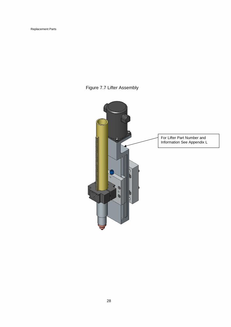
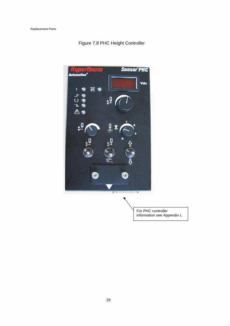
8.1 TORCH LIFTING OPTIONS
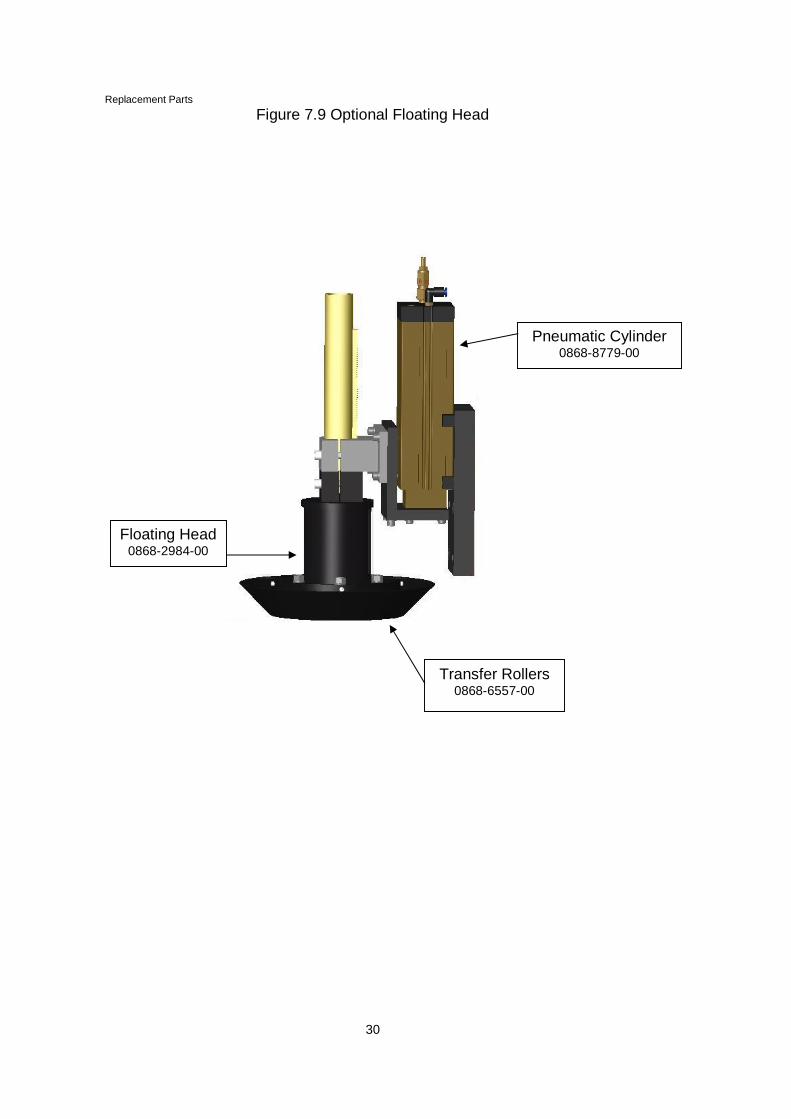
The Monograph Millennium is available with ahigh-speed model "H" motorized torch lifter or apneumatic floating head. The motorized torchlifter version comes with initial height sensingand utilizes an Innerlogic ATC for arc voltagefeed back position control. The pneumaticfloating head version is recommended for lightgauge only applications.
8.2 CUTTING SYSTEMS
Cutting systems that are supported on theMonograph Millennium include the HyperthermPowermax 1000, 1250 and 1650 plasma cuttingsystems. These systems support productioncutting of 3/8" mild steel with limited cutting of5/8" plate.
A-1
APPENDIX AMONOGRAPH MILLENNIUM /CUTTER II
List of Terms and Abbreviations
Abbreviation Term
AC Alternating Currentamp(s) Ampere(s)BTU British Thermal Unitsccw Counter-ClockwiseCGA Compressed Gas AssociationCSA Canadian Standards Associationcw Clockwisedia. DiameterDVM Digital Volt MeterE-Stop Emergency StopHHCS Hex Head Cap ScrewHz Hertzin InchesINC. Incorporatedipm Inches per MinutekPa KilopascalsL/H Left HandM MeterMFD Microfaradmm MillimeterNC Normally ClosedNEC National Electric CodeNo. NumberNO Normally OpenNPT National Pipe Threadoxy Oxygenoz OuncesPLC Programmable Logic Controllerpsi Pounds Per Square InchPWM Pulse Width ModulatorRecpt ReceptacleR/H Right HandSO# Sales Order NumberTP Test Pointvdc Volts direct current“ Inches--F Female--M Male
Page left intentionally blank
F-1
APPENDIX F
PLASMA OPERATION
GENERAL PLASMA CUTTING INFORMATION
Prior to cutting with plasma, you must have the gas settings for the plate thickness,arc voltage, current, speed settings in the CNC set correctly.
SINGLE PLASMA
Single plasma operation starts by selecting plasma one (1) on the operators’ controlunit. The button selected enables all functions for the plasma station. This includesstart, torch height control and machine motion. Machine motion is a signal generatedfrom the plasma system when the main arc from the plasma system starts. Thesignals, plasma START and torch height control are signals generated from the CNCto the PLC and controlled from the parameters for plasma setups. The CNC must beset for plasma cutting with the correct settings for the plasma type and height controlused. The signals to plasma start and height control and from the plasma to themachine go through the PLC for the selected plasma. Selecting start from the CNCstarts the cutting process.
WARNING
Ensure all safety precautions and warnings are adhered to. All plasma cuttingradiates high levels of light and noise.
Page left intentionally blank
L-1
APPENDIX L
Hypertherm Sensor™ PHCPlasma Height Control
On KAR MONOGRAPHMILLENNIUM
Operation & Set Up Guide
Hypertherm Automation5 Technology Drive, Suite 300
W. Lebanon, NH 03784 USAPhone: 603-298-7970
Fax: 603-298-7977
Making people and machines more productive through process Automation
Automation
L-2
DISCLAIMER The information in this document is subject to change without notice andshould not be construed as a commitment by Hypertherm Automation®.Hypertherm Automation® assumes no responsibility for any errors that mayappear.
TRADEMARKS Hypertherm Automation is a wholly owned subsidiary of Hypertherm®, Inc.Sensor™ is a trademark of Hypertherm Automation.HyDefinition® Plasma is a reg. trademark of Hypertherm®, Inc.HyPerformance™ Plasma is a trademark of Hypertherm Automation.Other trademarks are properties of their respective owners.
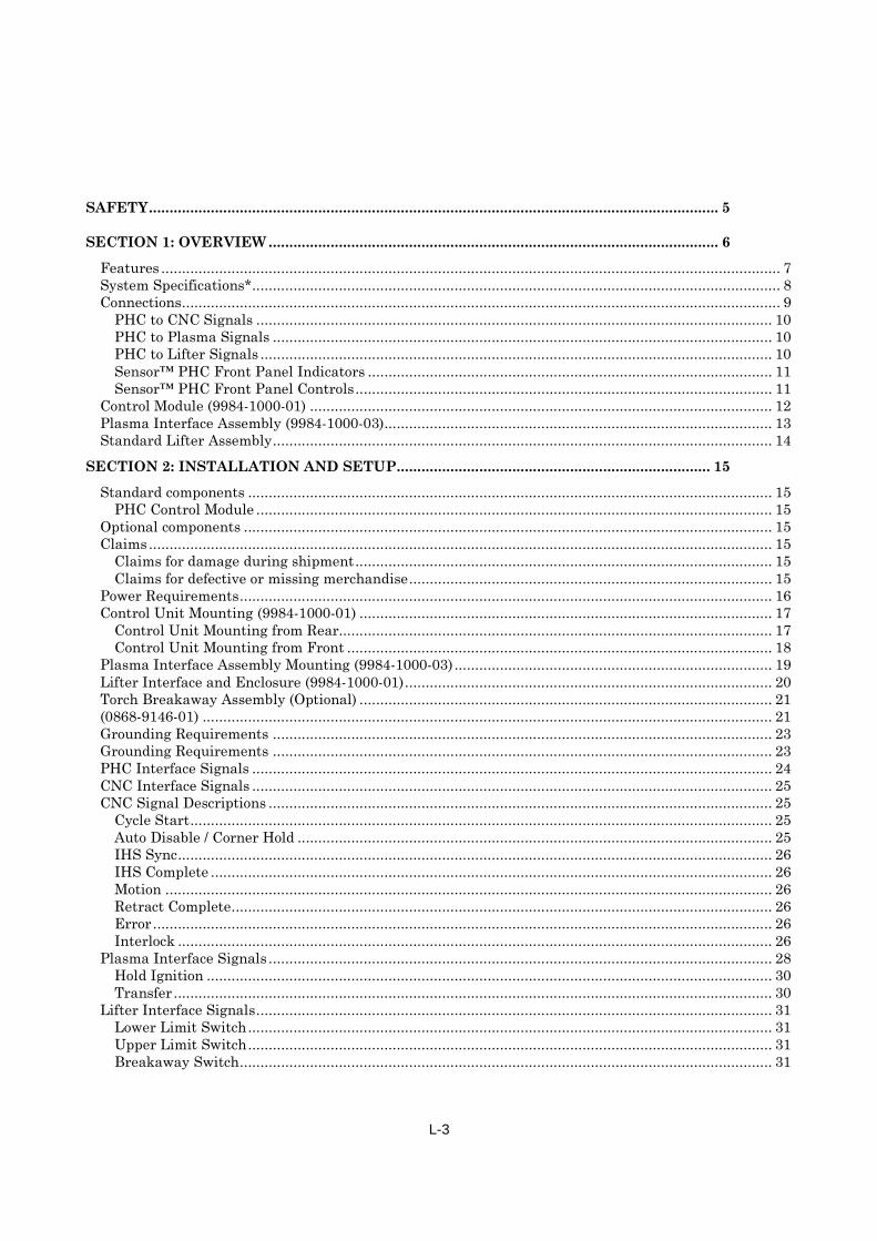
SECTION 2: INSTALLATION AND SETUP............................................................................ 15
Standard components ............................................................................................................................... 15PHC Control Module ............................................................................................................................. 15
Claims for damage during shipment..................................................................................................... 15Claims for defective or missing merchandise........................................................................................ 15
Power Requirements................................................................................................................................. 16Control Unit Mounting (9984-1000-01) .................................................................................................... 17
Control Unit Mounting from Rear......................................................................................................... 17Control Unit Mounting from Front ....................................................................................................... 18
Lifter Power Connections ......................................................................................................................... 32Motor Power .......................................................................................................................................... 32Lifter Brake........................................................................................................................................... 32
Read This ManualRead and understand this instructional manual, the cutting machine manuals, and your employer’ssafety practices. Note: This product is not designed to be field serviceable. Please return to anauthorized repair center for any required service.
Dangerous Machinery
Operation and maintenance of automated equipment involves potential hazards. Personnel shouldtake precautions to avoid injury.
Injury and entanglement may occur if hands and limbs come in contact with moving machinery.
KEEP HANDS CLEAR of dangerous moving machinery. All control, including manual, can beaffected using the remote interface
Loose fitting clothing or ties may become entangled in the machinery. These items should not beworn while operating or servicing the machine.
High Voltages
Electric shock can kill. Be sure this equipment is safely installed in accordance with the enclosedprocedures and specifications.
Avoid contact with electrical wires and cabling while power is on.
This equipment should only be opened by trained service personnel.
Please refer to the appropriate appendix in the Installation Guide provided with your control fordetails on safety certification for that product.
L-6
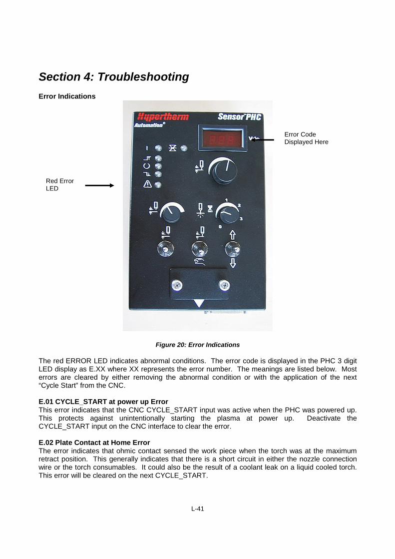
Section 1: Overview
Hypertherm’s Sensor™ PHC (SPHC-0001) is an economical plasma torch height control/initial heightsensing (THC/IHS) system designed for conventional plasma cutting applications on an X-Y cuttingtable. The system uses the plasma arc voltage to control the physical stand-off (distance) betweenthe torch and work piece during plasma arc cutting. Initial Height Sense (IHS) is accomplished byohmic contact sensing or by a limited force stall detection method. The Sensor™ PHC has beenoptimized for conventional plasma at or below 200 amps. The system is not recommended forHyDefinition® or HyPerformance™ cutting or for higher power applications. The system is notrecommended for use on a water table.
The Sensor™ PHC system includes the following:
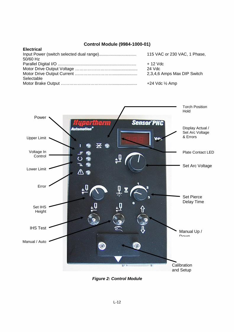
THC Control ModuleThe THC control module (ASSY-0214) houses a microcontroller, an operator control panel, and aLifter motor drive. This unit provides initial height sensing, arc voltage control and interfaces with thetorch Lifter, the CNC machine, and the plasma power supply through standard discrete I/Ointerfaces. The operator interface includes an LED display for set and actual arc voltage as well aserror codes. The control unit main functions are: arc voltage control/manual position mode, end ofcut retract, IHS test, pierce height, voltage controlled cut height, pierce delay; and access to setupand calibration adjustments. See Figure 2, Page 7.
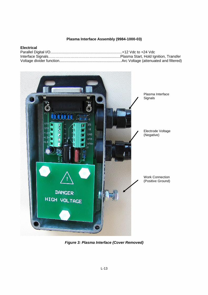
Plasma Interface AssemblyThe plasma interface (ASSY-0215) provides a clean standardized connection between the PHCcontrol module and the plasma power supply. The assembly can be mounted either to the back of orinternal to the plasma power supply. The voltage divider provides a filtered low voltage signal whichis derived from the cutting arc voltage. The interface also provides an enclosed terminal block foreasy connection to the interface signals. This interface assembly is not required on the newer (G3)Powermax® supplies since it is built-in to the supply. A Sensor™ PHC to Powermax® interface cableis all that is required. See Figure 3, Page 8.
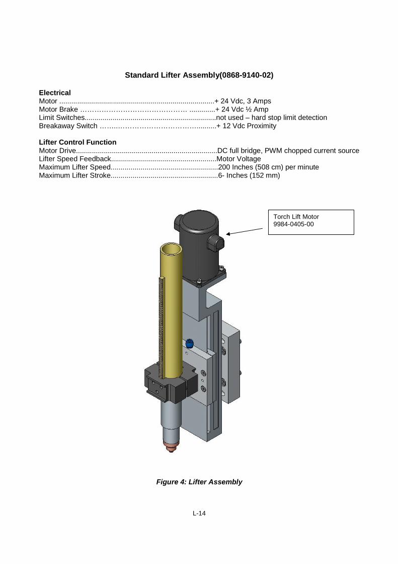
Lifter AssemblyThe torch lifter station (ASSY-0224), under control of the PHC control module, positions a torch headvertically above the work piece. Its maximum stroke is 6 inches (152 mm) between the home andlower limit. It is driven by a DC motor attached to a leadscrew. The control will interface to anoptional lower limit switch to detect maximum travel in the downward direction. The control will alsointerface to an optional home switch to detect when the lifter is in the uppermost position. Thestandard lifter does not use limit switches but has been designed to allow for hard stop limitdetection. A power-off brake disables power off motion of the torch. A torch breakaway is anintegral part of the lifter and provides a level of protection for the torch, lifter and X-Y table. Uponimpact, the breakaway releases from the locked position and allows the torch to float. A breakawayswitch detects when this protection has tripped and signals both the PHC control and the CNCmachine. See Figure 4, Page 14.
L-7
FeaturesSensor™ PHC Plasma Height Control is an advanced and economical automated height controlsystem for plasma shape cutting applications. This product utilizes advanced microprocessortechnology to automatically detect the plate and adjust torch position to a desired arc voltage setpoint during plasma cutting operations. This reduces operator input, improves accuracy andincreases productivity. The design of the Sensor™ PHC has been optimized for lower powerconventional plasma operation.
Features Sensor™ PHC can be used with any CNC Easy setup & operation Both manual & automatic operation modes Microprocessor control for increased sensitivity and control High positioning speeds possible with up to 6 amps continuous current and linear
adjustment over full range Built-in Torch Breakaway protection Built-in diagnostic and fault detection features Auto retract on plate contact 7 Segment LED display for set/actual arc voltage & error displays Power On Indicator Upper Limit Indicator Lower Limit Indicator In Position Indicator Attention / Error Indicator Torch Position Hold Indicator Plate Contact Indicator
Operator Switches: IHS Test, Auto / Manual, & Manual Up / Down
Operator Display: 3 digit 7 segment display for Set Volts, Actual Volts, & Error
Calibration Adjustments: Arc Voltage, Stall Force, Auto Kerf Detect Level
Setup DIP Switches: Max Motor Current, Arc Voltage Response, IHS Speed, AutoDelay, Int/Ext Pierce Delay, End of Cut Retract Height, AutoKerf Detect, Preflow during IHS, Limit Switches, BreakawaySwitch, Arc Voltage Calibration
Measuring Technology: Arc Voltage Feedback & Ohmic contact sensing
Interface Inputs/ Outputs: 8 outputs and 6 inputs optically isolated on “D” connectors
Control Dimensions: 6.2”(157mm)W x 4.3”(1.9mm)D x 10.4”(264mm)H
Operating Environment: 0 to 50C; 95% relative humidity (non-condensing)
*Information subject to change without notice.** With Standard supplied lifter mechanics
L-9
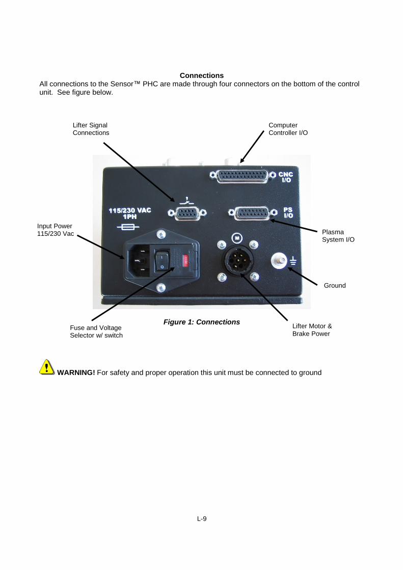
ConnectionsAll connections to the Sensor™ PHC are made through four connectors on the bottom of the controlunit. See figure below.
Figure 1: Connections
WARNING! For safety and proper operation this unit must be connected to ground
Ground
PlasmaSystem I/O
ComputerController I/O
Lifter Motor &Brake Power
Lifter SignalConnections
Input Power115/230 Vac
Fuse and VoltageSelector w/ switch
L-10
PHC to CNC SignalsAll signals to the CNC are connected through the 25 pin D-sub connector on the control unit. Fordetailed interfacing information, refer to the sections on PHC Interface Signals and CNC InterfaceSignals.
Inputs from CNC:Digital Cycle Start InputDigital Corner Hold InputDigital IHS Sync InputInterlock
PHC to Plasma SignalsAll signals to the plasma interface are connected through the 15 pin D-sub connector on the controlunit. These signals are easily connected through the Plasma Interface Unit or directly to aPowermax® G3 supply using a G3 Interface Cable. For more detailed information, refer to thesection on Plasma Interface.
Outputs to Plasma:Digital Plasma Start OutputDigital Hold Ignition Output
Inputs from Plasma:Digital Transfer InputAnalog Attenuated Arc Voltage
PHC to Lifter SignalsAll signals to the lifter are connected through the 9 pin D-Sub connector on the control unit. For moredetailed information refer to the section on lifter Interface.
Inputs from Lifter:Digital Upper Limit SwitchDigital Lower Limit SwitchDigital Breakaway SwitchAnalog Tip Touch Sense
PHC to Lifter Power ConnectionsAll power connections to the lifter are coupled through the 7 pin circular connector on the control unit.For more detailed information, refer to the section on lifter Interface.
Outputs to Lifter:Motor Drive 24V PWMPower Off Brake 24Vdc
L-11
Sensor™ PHC Front Panel IndicatorsGreen PowerYellow Upper LimitGreen In PositionYellow Lower LimitRed Attention / Error CodeYellow Corner / Kerf HoldRed Plate ContactRed 3 digit Set / Actual Arc Voltage – Error Number – Set Pierce Height & Delay
Sensor™ PHC Front Panel ControlsMultiturn Rotary Pot Set Arc VoltageRotary Pot Pierce Height RetractRotary Pot Pierce Delay TimeMomentary Toggle Sw IHS TestToggle Sw Auto / ManualMomentary 3 pos Toggle Manual Up / Down
L-12
Control Module (9984-1000-01)ElectricalInput Power (switch selected dual range)................................ 115 VAC or 230 VAC, 1 Phase,50/60 HzParallel Digital I/O ................................................................... + 12 VdcMotor Drive Output Voltage ………………………..................... 24 VdcMotor Drive Output Current ………………………..................... 2,3,4,6 Amps Max DIP SwitchSelectableMotor Brake Output ………………………………...................... +24 Vdc ½ Amp
Figure 2: Control Module
Calibrationand Setup
Display Actual /Set Arc Voltage& Errors
Set Arc Voltage
Set PierceDelay Time
Manual Up /Down
Manual / Auto
IHS Test
Set IHSHeight
Error
Lower Limit
Voltage InControl
Upper Limit
Power
Torch PositionHold
Plate Contact LED
L-13
Plasma Interface Assembly (9984-1000-03)
ElectricalParallel Digital I/O.....................................................................+12 Vdc to +24 VdcInterface Signals……………………………………...................Plasma Start, Hold Ignition, TransferVoltage divider function............................................................Arc Voltage (attenuated and filtered)
Figure 3: Plasma Interface (Cover Removed)
Plasma InterfaceSignals
Electrode Voltage(Negative)
Work Connection(Positive Ground)
L-14
Standard Lifter Assembly(0868-9140-02)
ElectricalMotor ..............................................................................+ 24 Vdc, 3 AmpsMotor Brake ……………………………………… .............+ 24 Vdc ½ AmpLimit Switches..................................................................not used – hard stop limit detectionBreakaway Switch ……..……………………………..........+ 12 Vdc Proximity
Lifter Control FunctionMotor Drive.......................................................................DC full bridge, PWM chopped current sourceLifter Speed Feedback.....................................................Motor VoltageMaximum Lifter Speed......................................................200 Inches (508 cm) per minuteMaximum Lifter Stroke......................................................6- Inches (152 mm)
Figure 4: Lifter Assembly
Torch Lift Motor9984-0405-00
L-15
Section 2: Installation and Setup
Upon receipt, the PHC system should include the following standard and optional components, ifordered:
Standard components
PHC Control Module
Power cord - 6.5 ft./2 mLifter assembly with torch breakawayPlasma Interface AssemblyInterface cables
If your unit was damaged during shipment, you must file a claim with the carrier. Hypertherm willfurnish you with a copy of the bill of lading upon request. If you need additional assistance, pleasecontact your Hypertherm Customer Service agent.
Claims for defective or missing merchandise
If any of the merchandise is defective or missing, call your authorized Hypertherm distributor. If youneed additional assistance, please contact your Hypertherm Customer Service agent.
L-16
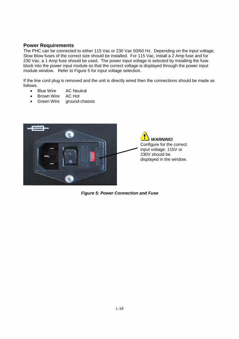
Power RequirementsThe PHC can be connected to either 115 Vac or 230 Vac 50/60 Hz. Depending on the input voltage,Slow Blow fuses of the correct size should be installed. For 115 Vac, install a 2 Amp fuse and for230 Vac, a 1 Amp fuse should be used. The power input voltage is selected by installing the fuseblock into the power input module so that the correct voltage is displayed through the power inputmodule window. Refer to Figure 5 for input voltage selection.
If the line cord plug is removed and the unit is directly wired then the connections should be made asfollows.
Blue Wire AC Neutral Brown Wire AC Hot Green Wire ground-chassis
Figure 5: Power Connection and Fuse
WARNING!Configure for the correctinput voltage. 115V or230V should bedisplayed in the window.
L-17
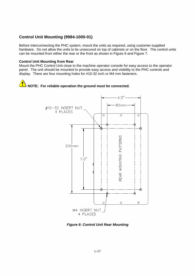
Control Unit Mounting (9984-1000-01)
Before interconnecting the PHC system, mount the units as required, using customer-suppliedhardware. Do not allow the units to lie unsecured on top of cabinets or on the floor. The control unitscan be mounted from either the rear or the front as shown in Figure 6 and Figure 7.
Control Unit Mounting from RearMount the PHC Control Unit close to the machine operator console for easy access to the operatorpanel. The unit should be mounted to provide easy access and visibility to the PHC controls anddisplay. There are four mounting holes for #10-32 inch or M4 mm fasteners.
NOTE: For reliable operation the ground must be connected.
Figure 6: Control Unit Rear Mounting
L-18
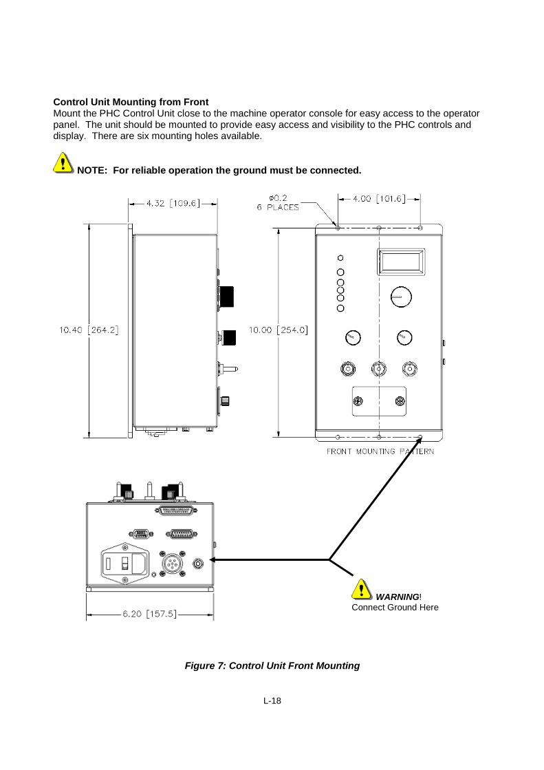
Control Unit Mounting from FrontMount the PHC Control Unit close to the machine operator console for easy access to the operatorpanel. The unit should be mounted to provide easy access and visibility to the PHC controls anddisplay. There are six mounting holes available.
NOTE: For reliable operation the ground must be connected.
Figure 7: Control Unit Front Mounting
WARNING!Connect Ground Here
L-19
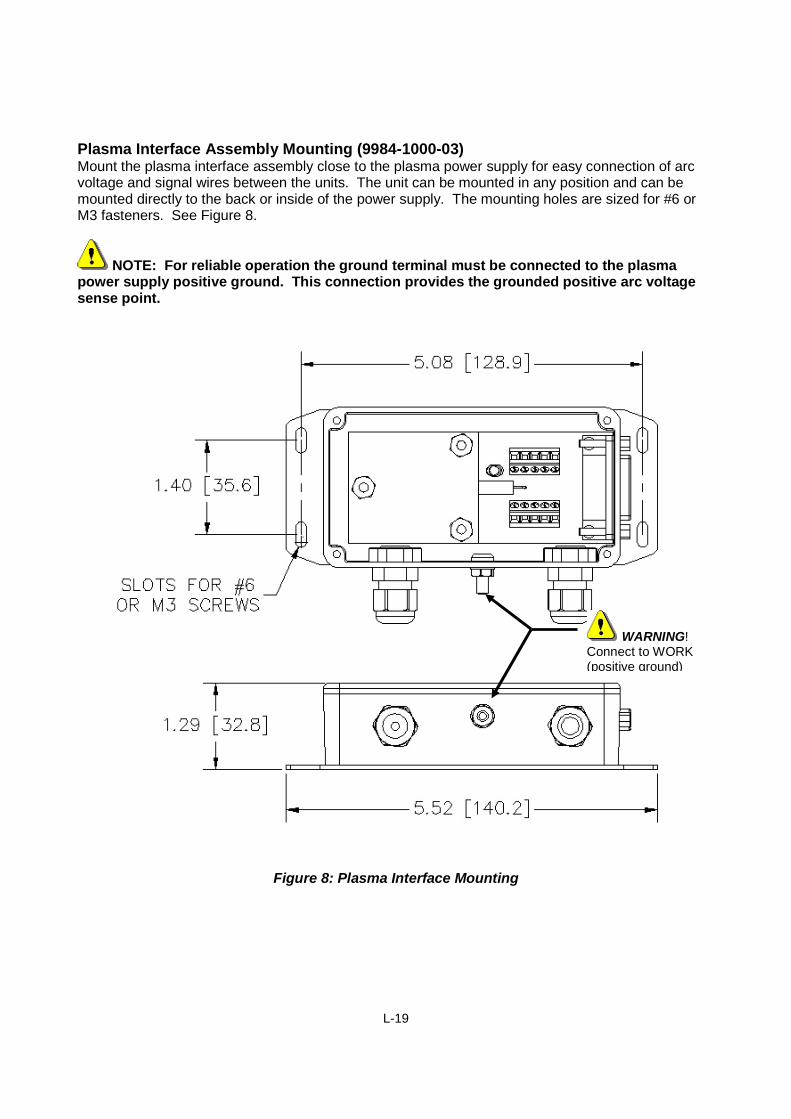
Plasma Interface Assembly Mounting (9984-1000-03)Mount the plasma interface assembly close to the plasma power supply for easy connection of arcvoltage and signal wires between the units. The unit can be mounted in any position and can bemounted directly to the back or inside of the power supply. The mounting holes are sized for #6 orM3 fasteners. See Figure 8.
NOTE: For reliable operation the ground terminal must be connected to the plasmapower supply positive ground. This connection provides the grounded positive arc voltagesense point.
Figure 8: Plasma Interface Mounting
WARNING!Connect to WORK(positive ground)
L-20
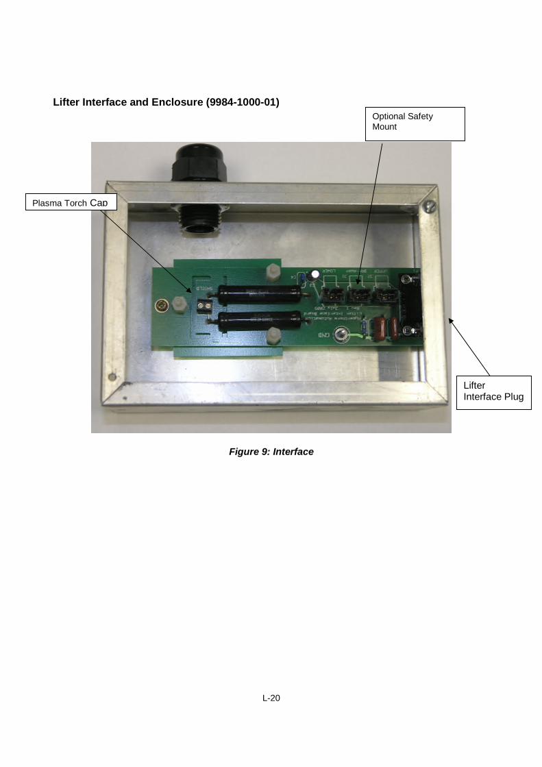
Lifter Interface and Enclosure (9984-1000-01)
Figure 9: Interface
Optional SafetyMount
Plasma Torch Cap
LifterInterface Plug
L-21
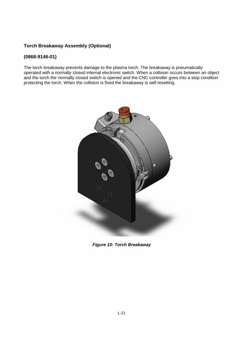
Torch Breakaway Assembly (Optional)
(0868-9146-01)
The torch breakaway prevents damage to the plasma torch. The breakaway is pneumaticallyoperated with a normally closed internal electronic switch. When a collision occurs between an objectand the torch the normally closed switch is opened and the CNC controller goes into a stop conditionprotecting the torch. When the collision is fixed the breakaway is self-resetting.
Figure 10: Torch Breakaway
L-22
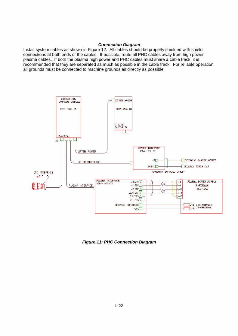
Connection DiagramInstall system cables as shown in Figure 12. All cables should be properly shielded with shieldconnections at both ends of the cables. If possible, route all PHC cables away from high powerplasma cables. If both the plasma high power and PHC cables must share a cable track, it isrecommended that they are separated as much as possible in the cable track. For reliable operation,all grounds must be connected to machine grounds as directly as possible.
Figure 11: PHC Connection Diagram
L-23
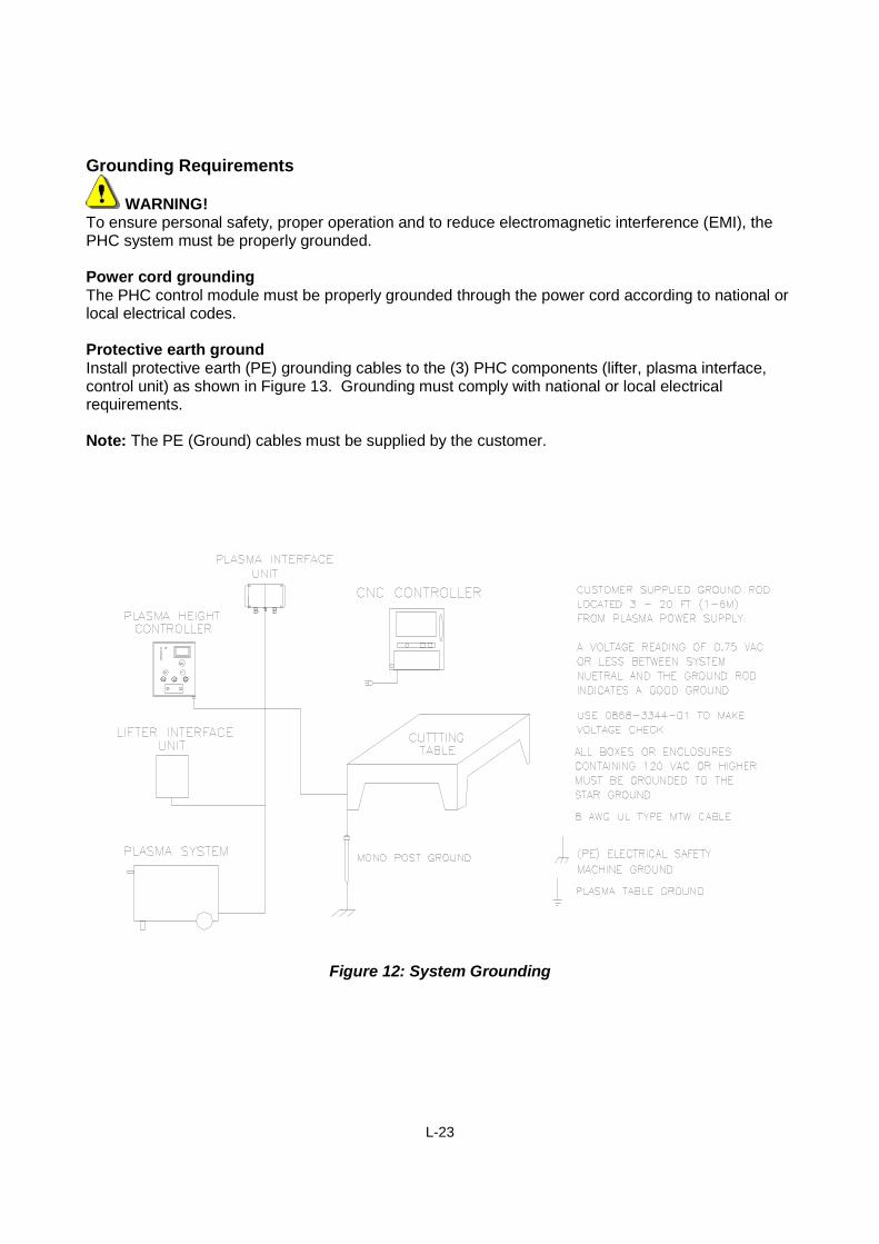
Grounding Requirements
WARNING!To ensure personal safety, proper operation and to reduce electromagnetic interference (EMI), thePHC system must be properly grounded.
Power cord groundingThe PHC control module must be properly grounded through the power cord according to national orlocal electrical codes.
Protective earth groundInstall protective earth (PE) grounding cables to the (3) PHC components (lifter, plasma interface,control unit) as shown in Figure 13. Grounding must comply with national or local electricalrequirements.
Note: The PE (Ground) cables must be supplied by the customer.
Figure 12: System Grounding
L-24
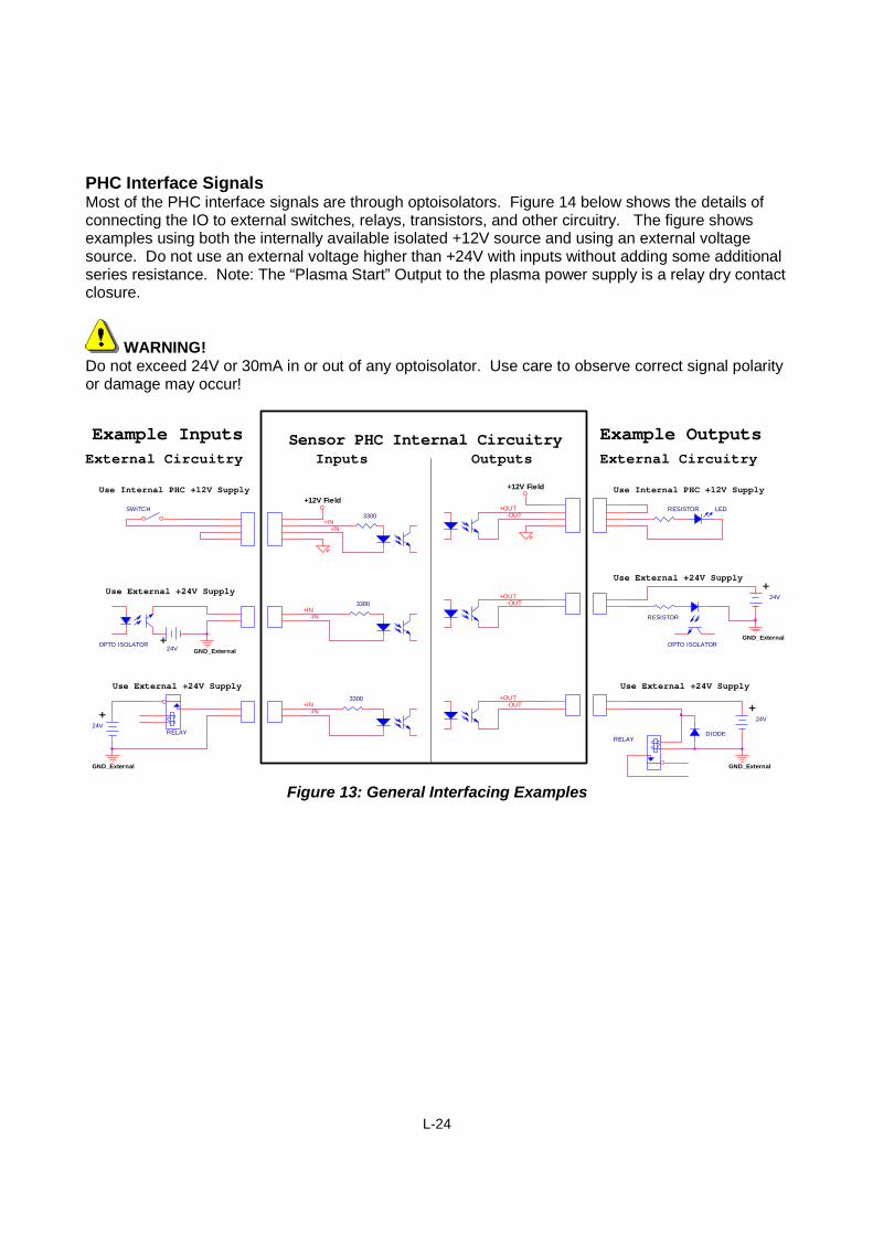
PHC Interface SignalsMost of the PHC interface signals are through optoisolators. Figure 14 below shows the details ofconnecting the IO to external switches, relays, transistors, and other circuitry. The figure showsexamples using both the internally available isolated +12V source and using an external voltagesource. Do not use an external voltage higher than +24V with inputs without adding some additionalseries resistance. Note: The “Plasma Start” Output to the plasma power supply is a relay dry contactclosure.
WARNING!Do not exceed 24V or 30mA in or out of any optoisolator. Use care to observe correct signal polarityor damage may occur!
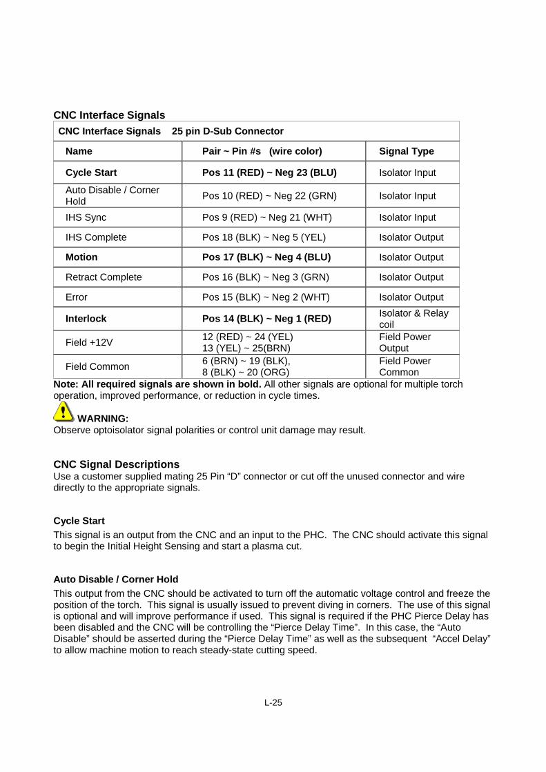
Note: All required signals are shown in bold. All other signals are optional for multiple torchoperation, improved performance, or reduction in cycle times.
WARNING:Observe optoisolator signal polarities or control unit damage may result.
CNC Signal DescriptionsUse a customer supplied mating 25 Pin “D” connector or cut off the unused connector and wiredirectly to the appropriate signals.
Cycle Start
This signal is an output from the CNC and an input to the PHC. The CNC should activate this signalto begin the Initial Height Sensing and start a plasma cut.
Auto Disable / Corner Hold
This output from the CNC should be activated to turn off the automatic voltage control and freeze theposition of the torch. This signal is usually issued to prevent diving in corners. The use of this signalis optional and will improve performance if used. This signal is required if the PHC Pierce Delay hasbeen disabled and the CNC will be controlling the “Pierce Delay Time”. In this case, the “AutoDisable” should be asserted during the “Pierce Delay Time” as well as the subsequent “Accel Delay”to allow machine motion to reach steady-state cutting speed.
L-26
IHS Sync
This optional CNC output is used to synchronize torches in a multiple torch installation. For singletorch installations, this signal is not required and can be left unconnected. The CNC should issuethis signal to delay plasma torch ignition until all torches in a multiple torch configuration havecompleted their IHS sequence and are in position and ready to fire. When the CNC releases (de-activates) this signal, the torch will ignite and the plasma torch will begin piercing.
IHS Complete
This optional signal is an output from the PHC and an input to the CNC. This signal is used toindicate that the Initial Height Sensing is complete and that a torch is in position and ready to fire.For multiple torch installations, the CNC should wait for all active torches to indicate IHS COMPLETEbefore simultaneously releasing all IHS SYNC signals to all allow the torches to ignite. For singletorch installations, this signal is not required.
Motion
This signal is an output from the PHC and an input to the CNC. The signal is issued after plasmaignition and the PHC set Pierce Delay Time. It indicates to the CNC that the pierce delay is completeand the cut motion should begin. If the CNC will perform all pierce delay timing, then theEXT_PIERCE_DELAY - DIP switch on the PHC should be turned ON. This will force the PHCpierce delay to be zero and disable the front panel Pierce Delay control. If the CNC is controlling thepierce delay then it is the CNC’s responsibility to use the AUTO_DISABLE / HOLD signal to hold offthe arc voltage control until the Pierce and Accel Times have elapsed.
Retract Complete
This signal is an output from the PHC that is active when a cut has been completed and the torchhas been retracted to the selected retract height. The CNC can use this signal to delay rapid transitto the next cut until the torch has been raised and will safely clear any tip-ups. The use of this signalis optional.
Error
This signal is output by the PHC for any errors. The actual error number will be displayed on thePHC front panel LED display.
Interlock
This is a normally closed contact closure provided by the CNC to allow PHC motion. If this contact isopened, the PHC motor drive will be de-energized. JUMPER IF NOT USED
L-27
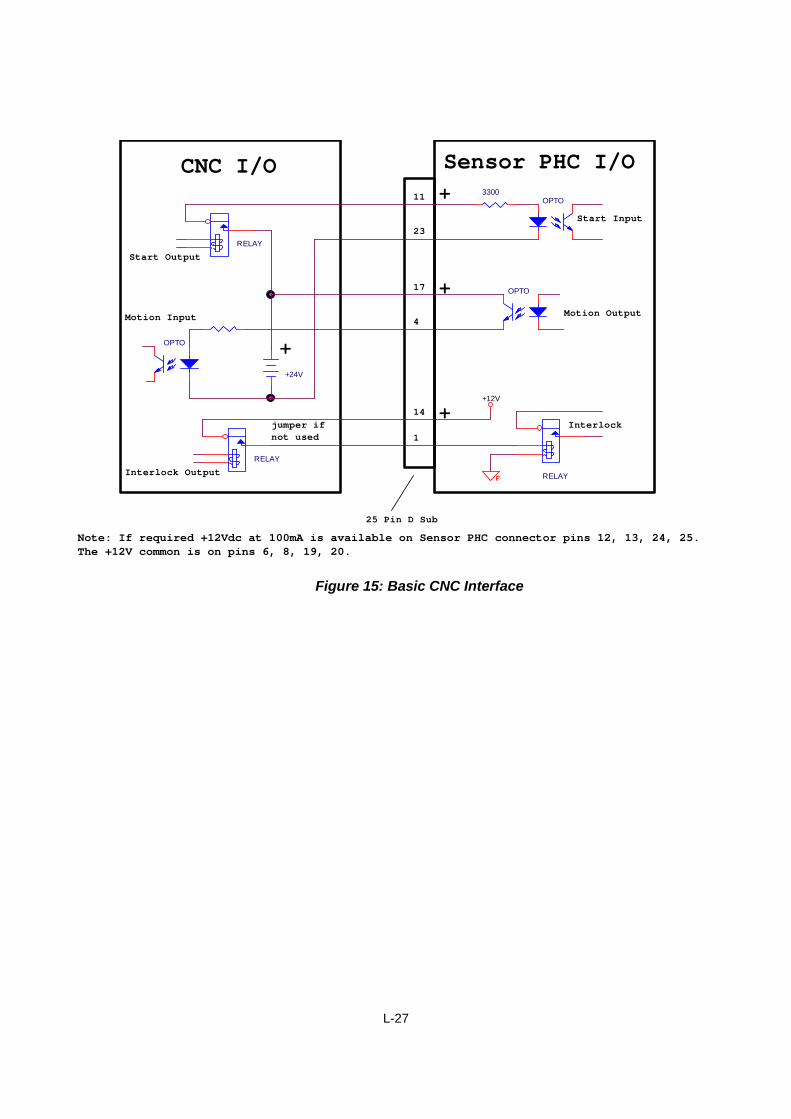
RELAY
Start Output
Start Input
Motion Output
Interlock
Motion Input
Sensor PHC I/OCNC I/O
Interlock Output
+
+
+
11
23
17
4
14
1
RELAY
OPTO3300
+24V
25 Pin D Sub
OPTO
Note: If required +12Vdc at 100mA is available on Sensor PHC connector pins 12, 13, 24, 25.The +12V common is on pins 6, 8, 19, 20.
RELAY
jumper if
not used
+12V
OPTO +
Figure 15: Basic CNC Interface
L-28
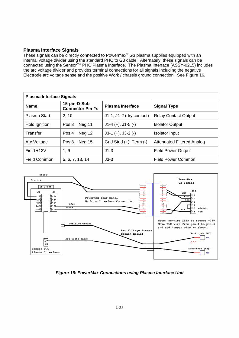
Plasma Interface SignalsThese signals can be directly connected to Powermax® G3 plasma supplies equipped with aninternal voltage divider using the standard PHC to G3 cable. Alternately, these signals can beconnected using the Sensor™ PHC Plasma Interface. The Plasma Interface (ASSY-0215) includesthe arc voltage divider and provides terminal connections for all signals including the negativeElectrode arc voltage sense and the positive Work / chassis ground connection. See Figure 16.
Arc Voltage Pos 8 Neg 15 Gnd Stud (+), Term (-) Attenuated Filtered Analog
Field +12V 1, 9 J1-3 Field Power Output
Field Common 5, 6, 7, 13, 14 J3-3 Field Power Common
123456789
1011121314
1234567891011121314
Note: re-wire XFER to source +24V.Move BLK wire from pin-4 to pin-6and add jumper wire as shown.
Arc Voltage AccessStrain Relief
PowerMax rear panelMachine Interface Connection
1
3
2
5
4 2
1
4
3
5
15 D-Sub
1
4
3
2
5
WHT
Sensor PHCPlasma Interface
6
YEL
RED
+24VdcBLKCom
J19J3J1
J15
J16
PowerMaxG3 Series
Work (pos GND)
Electrode (neg)
Start-
Start +
Arc Volts (neg)
Xfer+
Xfer-
Positive Ground
Figure 16: PowerMax Connections using Plasma Interface Unit
L-29
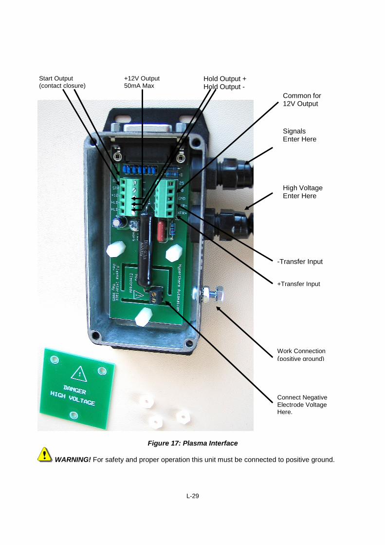
Figure 17: Plasma Interface
WARNING! For safety and proper operation this unit must be connected to positive ground.
Work Connection
(positive ground)
Connect NegativeElectrode VoltageHere.
Start Output(contact closure)
+12V Output50mA Max
Hold Output +Hold Output -
Common for12V Output
-Transfer Input
SignalsEnter Here
High VoltageEnter Here
+Transfer Input
L-30
Work
Positive Ground
Electrode (Neg)
GND_External
+12V Field
PLASMA START (+24V)
HOLD
IGNITION
TRANSFER
J112345 HLD-
J312345
HLD+
XFR-
RELAY
OPTO
OPTO 3300
External Plasma Supply(using External +24V)
STRSTR
XFR+
+24V External
GND_External
RELAY 24V coil
RELAY
DIODE
12
Electrode (Neg)
Sensor PHC PlasmaInterface I/O
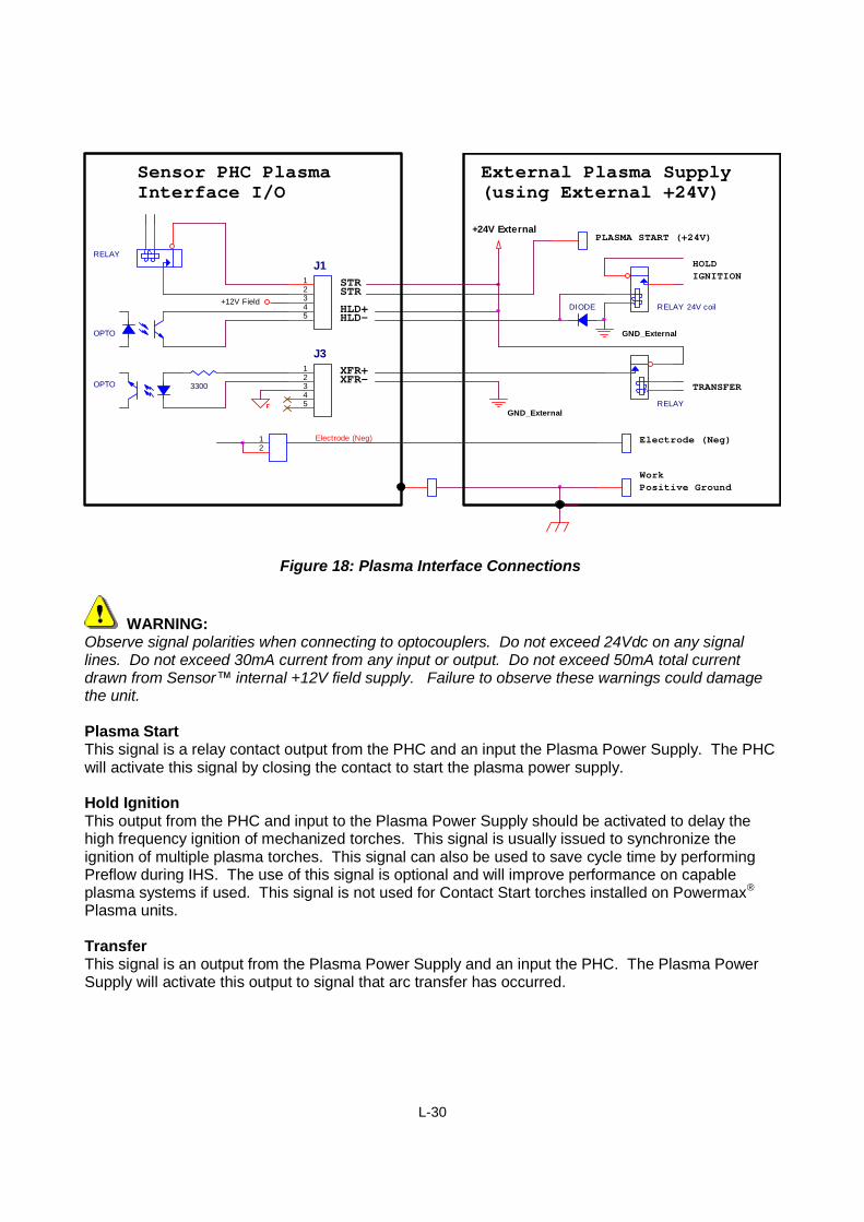
Figure 18: Plasma Interface Connections
WARNING:Observe signal polarities when connecting to optocouplers. Do not exceed 24Vdc on any signallines. Do not exceed 30mA current from any input or output. Do not exceed 50mA total currentdrawn from Sensor™ internal +12V field supply. Failure to observe these warnings could damagethe unit.
Plasma StartThis signal is a relay contact output from the PHC and an input the Plasma Power Supply. The PHCwill activate this signal by closing the contact to start the plasma power supply.
Hold IgnitionThis output from the PHC and input to the Plasma Power Supply should be activated to delay thehigh frequency ignition of mechanized torches. This signal is usually issued to synchronize theignition of multiple plasma torches. This signal can also be used to save cycle time by performingPreflow during IHS. The use of this signal is optional and will improve performance on capableplasma systems if used. This signal is not used for Contact Start torches installed on Powermax®
Plasma units.
TransferThis signal is an output from the Plasma Power Supply and an input the PHC. The Plasma PowerSupply will activate this output to signal that arc transfer has occurred.
L-31
Lifter Interface SignalsThese signals can be directly connected to a Sensor™ PHC standard lifter using the supplied cable.
Lifter Interface Signals 9 pin D-Sub Connector
Name Pin #s Signal Type
Lower Limit Switch 6 - Switch to Common Isolator Input
Upper Limit Switch 2 - Switch to Common Isolator Input
Torch Breakaway Switch 7 - Switch to Common Isolator Input
Torch Tip Touch Sense 4, 5, 9 Attenuated Filtered Analog
Field +12V 1 Field Power Output
Field Common 3, 8 Field Power Common
Lower Limit Switch
This signal is an output from the lifter and an input to the PHC. The lifter can activate this signal toindicate that the lifter has reached the upper range of motion. The normally open/closed sense ofthis signal can be changed through setup DIP Switch #14. The use of a limit switch is optional. ThePHC standard lifter does not include limit switches and the PHC detects the hard stop limits bymonitoring motor speed.
Upper Limit Switch
This signal is an output from the lifter and an input to the PHC. The lifter can activate this signal toindicate that the lifter has reached the lower range of motion. The normally open/closed sense of thissignal can be changed through setup DIP Switch #14. The use of a limit switch is optional. The PHCstandard lifter does not include limit switches and the PHC detects the hard stop limits by monitoringmotor speed.
Breakaway Switch
This signal is an output from the lifter and an input to the PHC. The lifter can activate this signal toindicate that the mechanical torch breakaway has tripped. The normally open/closed sense of thissignal can be changed through setup DIP Switch #15. The use of a torch breakaway switch isoptional.
L-32
Lifter Power ConnectionsThese connections can be made directly to a Sensor™ PHC standard lifter using the supplied cable.
Lifter Power Connections 7 pin Circular Connector
Name Pin #s Signal Type
Motor Power – Up Direction Positive 1 Negative 2 PWM H Bridge Output
Lifter Brake Positive 4 Negative 5 +24Vdc Output
Chassis Ground 6
Motor Power
This signal is an output from the PHC. It is output from a PWM controlled “H” bridge motor drive.The maximum current level can be set using DIP switches #1 and #2. This output is intended todrive a 24Vdc permanent magnet motor.
Lifter Brake
This output from the PHC is a 24Vdc signal to an electromagnetic brake. When this signal isenergized, the brake is released to allow lifter motion.
L-33
DIP Switch Setup
Figure 19: Setup DIP Switches
Switch SettingsSwitch settings for control module operation and setup outlined below. Note*: Default switchsettings (as shipped) are indicated in BOLD text.
As shown in the figure above, the Setup DIP Switches are divided into two groups of eight switches.The top set of switches is numbered SW1 through SW8 and the bottom set of switches is numberedSW9 through SW16.
SW1 SW2 Maximum Motor Current / Poweron on Max Current = 2 Amps, 50 Wattson off Max Current = 3 Amps, 75 Watts *off on Max Current = 4 Amps, 100 Wattsoff off Max Current = 6 Amps, 150 Watts
Set DIP switches SW1 and SW2 to the rated current of the lifter motor. This is the maximum currentthat will be applied and is directly related to the motor power rating. This setting is also used todetermine the minimum applied current for stall sensing and to calculate the motor speed based onthe measured motor voltage.
NOTE: For optimum performance it is important that these switches are set correctly. For thestandard lifter, these switches should be set for 3 Amps
Arc VoltageCalibrate
Auto KerfDetect Level
Stall ForceLevel
SW1 SW8
SW ON
SW OFF
SW16SW9
L-34
SW3 SW4 Voltage Control Response / Gainon on Gain = Low = +/- 4V In Position Rangeon off Gain = Med Low = +/- 2V In Position Range *off on Gain = Med High = +/- 1V In Position Rangeoff off Gain = High = +/- 0.5V In Position Range
Set DIP switches SW3 and SW4 to select the closed loop voltage control response. The DIPswitches should be set for the highest gain possible that yields an acceptable control response. Anacceptable response should be stable and should have a minimum overshoot. These settings will bea function of the lifter and motor combination. For faster lifters use a lower gain setting. Fastersettings may require the use of the “Corner Hold” signal from the CNC to prevent diving in thecorners. The control accuracy will be affected by this setting.
SW5 IHS Slow Approach / Retract Speedoff Speed = High = 30% of Max Speedon Speed = Low = 15% of Max Speed *
The setting of SW5 will affect the speed that is used when the torch is approaching the plate duringan IHS cycle. This set speed will also be used during retract from plate contact to the pierce heightand during the first seconds of low speed manual motion. This setting is a compromise betweenpositioning accuracy and cycle time. Set a speed that is as fast as possible and still provides therequired IHS range and fine manual motion accuracy.
SW6 Spare – Not Used
SW7 Auto Voltage Control Acceleration Delayoff High – Enable Voltage Control 1.0 Second after Pierce delayon Low – Enable Voltage Control 0.5 Second after Pierce delay *
The SW7 delay setting is used to allow the cutting machine to accelerate to steady state speedbefore starting the closed loop voltage control of torch height. The shorter delay should be used formost machines. For very large cutting machines, it may be necessary to use the longer delay toavoid diving into the plate during machine acceleration.
SW8 External Pierce Delayoff Normal – Internal Pierce Delay *on CNC will control – Front panel Pierce delay disabled
SW8 should be turned ON if the CNC will be used to time the pierce delay. When this switch is ON,the front panel control for pierce time is disabled and the PHC will use a pierce time of zero. It is nowthe responsibility of the CNC to assert the AUTO / CORNER HOLD and wait for the MOTION signaland then begin timing the Pierce Delay Time. Once the Pierce Time has elapsed, the CNC shouldbegin the actual cutting machine motion and start to time the Acceleration Delay. Once theAcceleration Delay time has elapsed, the CNC should remove the AUTO / CORNER HOLD andallow the PHC to control the torch height.
L-35
SW9 SW10 End of Cut Retract Timeon on Retract = Low = 0.25 Sec @ Max Speed (0.8” std lifter)on off Retract = Med Low = 0.5 Sec @ Max Speed (1.6” std lifter)*off on Retract = Med High = 1.0 Sec @ Max Speed (3.3” std lifter)off off Retract = High = 1.5 Sec @ Max Speed (5.0” std lifter)
SW9 and SW10 control the end of cut retract. This setting should be set as low as possible toachieve optimum cycle times and still clear worst case tip-ups. The end of cut retract moves at themaximum lifter speed.
SW11 Automatic Kerf Detectoff Automatic Kerf Detection is disabled *on Normal – PHC will detect Kerf crossings and auto HOLD
For the Automatic Kerf Detection to operate properly, the Kerf Threshold Pot must be adjusted to thecorrect level. The correct level is low enough to trip the Kerf Detection when crossing a Kerf, buthigh enough that nuisance trips are avoided during normal cutting. This pot should be adjusted byviewing the Yellow “Corner / Kerf Hold LED” during a test cut.
SW12 Preflow During IHSoff Normal – Plasma Start and Preflow after IHS – Contact Start Torch *on Plasma Start and Preflow during IHS with capable plasma systems
Note: This function must be disabled for Powermax® contact start torches.
This function is only used with high frequency start mechanized torches. With mechanized torches,this function can save cycle time by performing IHS and torch preflow during the same period of time.When “Preflow During IHS” is active, the “Start” and “Ignition Hold” output signals are applied to theplasma system during the IHS process. This allows the plasma system to begin the gas preflowrequirement during the same period of time when the PHC lifter is positioning the torch at the correctPierce Height. Once the PHC lifter has been positioned at the correct “Pierce Height”, the “IgnitionHold” output is removed allowing the torch to start and the cutting process to begin.
SW13 Spare – Not Used
SW14 Lifter Limit Switchesoff (Sw NO) Close on Limit – or switches not used, lifter hard stops *on (Sw NC) Open on Limit – Use normally closed lifter inputs
For the standard lifter, limit switches are not used. The PHC senses the lifter upper and lower limitsby sensing when the lifter hard stops at the travel limits.
L-36
SW15 Torch Breakaway Switchoff (Sw NC) Close on Breakaway – or switch not usedon (Sw NO) Open on Breakaway – Use normally open switch input *
For the standard lifter, the torch breakaway uses a normally open proximity switch. When thebreakaway is installed the switch will close and when the breakaway is tripped the switch will open.
SW16 Arc Voltage Calibration Modeoff Normal – Display set arc voltage during Idle state *on Display Actual Arc Voltage during Idle state for Calibration
For normal operation, this switch should be set to OFF.
This switch is used to display the actual arc voltage on the PHC display. This allows the arc voltageto be calibrated by adjusting the Arc Voltage adjustment pot. When the calibration mode is active,the PHC will display “X.X.X.” with the X’s indicating the measured arc voltage and all the decimalpoints on to indicate calibration mode.
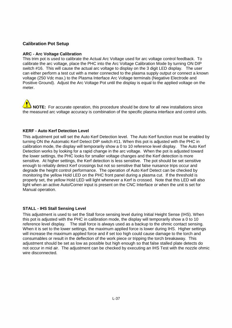
When calibration mode is active the display can be temporarily overridden by adjusting either theKerf Detect Level or the Stall Force. Adjusting either the Kerf Detect or Stall Force will result in a 0 to10 reference level being temporarily displayed. After one second of inactivity the display will revertback to the measured arc voltage.
NOTE: The arc voltage calibration procedure should be performed on all newinstallations as the actual measured arc voltage accuracy is a combination of the individualplasma interface and control units.
L-37
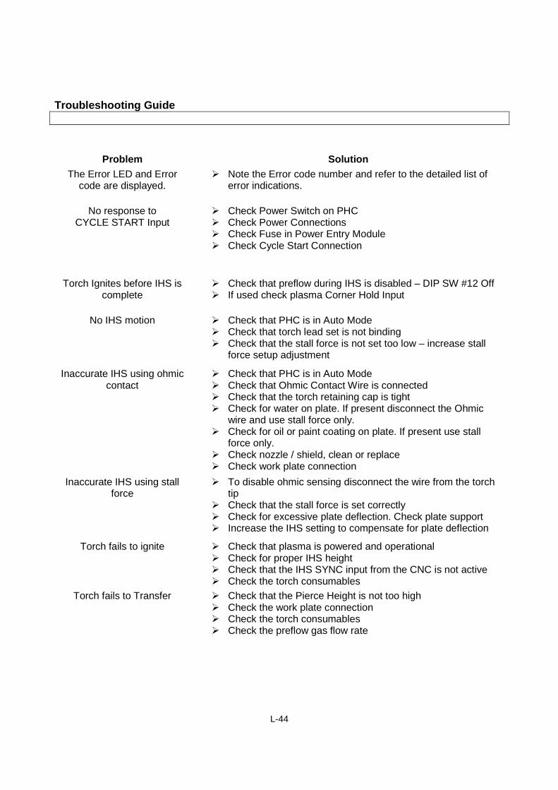
Calibration Pot Setup
ARC - Arc Voltage CalibrationThis trim pot is used to calibrate the Actual Arc Voltage used for arc voltage control feedback. Tocalibrate the arc voltage, place the PHC into the Arc Voltage Calibration Mode by turning ON DIPswitch #16. This will cause the actual arc voltage to display on the 3 digit LED display. The usercan either perform a test cut with a meter connected to the plasma supply output or connect a knownvoltage (250 Vdc max.) to the Plasma Interface Arc Voltage terminals (Negative Electrode andPositive Ground). Adjust the Arc Voltage Pot until the display is equal to the applied voltage on themeter.
NOTE: For accurate operation, this procedure should be done for all new installations sincethe measured arc voltage accuracy is combination of the specific plasma interface and control units.
KERF - Auto Kerf Detection Level
This adjustment pot will set the Auto Kerf Detection level. The Auto Kerf function must be enabled byturning ON the Automatic Kerf Detect DIP switch #11. When this pot is adjusted with the PHC incalibration mode, the display will temporarily show a 0 to 10 reference level display. The Auto KerfDetection works by looking for a rapid change in the arc voltage. When the pot is adjusted towardthe lower settings, the PHC looks for smaller voltage changes and the Kerf detection is moresensitive. At higher settings, the Kerf detection is less sensitive. The pot should be set sensitiveenough to reliably detect Kerf crossings but not so sensitive that false nuisance trips occur anddegrade the height control performance. The operation of Auto Kerf Detect can be checked bymonitoring the yellow Hold LED on the PHC front panel during a plasma cut. If the threshold isproperly set, the yellow Hold LED will light whenever a Kerf is crossed. Note that this LED will alsolight when an active Auto/Corner input is present on the CNC Interface or when the unit is set forManual operation.
STALL - IHS Stall Sensing Level
This adjustment is used to set the Stall force sensing level during Initial Height Sense (IHS). Whenthis pot is adjusted with the PHC in calibration mode, the display will temporarily show a 0 to 10reference level display. The stall force is always used as a backup to the ohmic contact sensing.When it is set to the lower settings, the maximum applied force is lower during IHS. Higher settingswill increase the maximum applied force and if set too high could cause damage to the torch andconsumables or result in the deflection of the work piece or tripping the torch breakaway. Thisadjustment should be set as low as possible but high enough so that false stalled plate detects donot occur in mid air. The adjustment can be checked by executing an IHS Test with the nozzle ohmicwire disconnected.
L-38
Section 3: Operation
Automated Torch Height Control (THC) Systems used in Mechanized Plasma Cutting are used toprovide the optimum height for the desired metal cutting process. The appropriate cut height iscrucial to the Plasma Process to provide the ability to transfer the Arc to the work piece for piercing /cutting and for optimum cut quality (bevel angle, etc).
With the Plasma Process there is a direct relationship between the cut voltage and the torch height(gap between the metal work surface and the torch electrode). By using the automated control tomonitor the working Arc (cut) Voltage, it can then control the Torch Height Control to maintain aspecific voltage set point.
L-39
Automatic OperationAutomatic voltage control operation is selected by placing the lower center toggle switch in the upperAuto position. In this mode the unit will automatically IHS to the set Pierce Height, Ignite the plasmatorch, wait for the torch to pierce the plate, and begin the cutting machine motion. The basicSensor™ PHC auto operation setup consists of three steps. The first step is to adjust the correct ArcVoltage Set point. The second step is to set and test the correct IHS Retract Height or Pierce Height.The final step is to set the Pierce Time Delay.
Set up guidelines are outlined below.
Set Arc VoltageUsing the larger multi-turn adjustment, set the desired arc voltage on the display. The starting pointfor this voltage should be included in the cut charts supplied with your plasma system. It is importantto remember that this voltage is just a starting point since the actual arc voltage will depend onconsumable wear, torch lead lengths, gas flow rates, and machine motion. For optimal cut qualityyou may need to make small adjustments around the nominal arc voltage that is specified in the cutcharts. The important item to control is the torch-tip to work height during a cut. The arc voltage isjust an indirect method to control this height.
Set IHS Retract or Pierce HeightUsing the lower left rotary control, set the desired IHS Retract Height. As this control is adjusted thedisplay will be temporarily overridden with a 0 to 10 reference level. This represents the desiredpierce height. The actual height should be available in the cut charts supplied with the plasmasystem. This setting is approximate because it will depend on whether the unit can sense the plateusing ohmic contact or must rely on the backup limited force stall sensing. This setting should bechecked by performing an IHS Test and checking for the correct pierce height. Each time the lowerleft IHS Test Switch is pressed, the torch should alternate between the set IHS Height and the end ofcut Retract Height. Continue testing and fine tuning this adjustment until the desired IHS Height isachieved. If the IHS speed (DIP SW #5) has been set to the normal low speed setting, then the IHSretract adjustment range should be between about 50 thousandths and 1/2 inch. If the IHS speedwas set to the high speed setting, then the IHS retract adjustment range should be between about1/10th inch and 1 inch.
Set Pierce Delay TimeUsing the lower right rotary control, set the desired pierce time delay. As this control is adjusted thedisplay will be temporarily overridden with a 0 to 4.0 second delay time. This is the time delaybetween igniting the torch and beginning the cut motion. The Pierce Delay is the time required forthe plasma torch to initially cut through the plate. This time delay should be included in the cut chartsprovided with your plasma system. To provide more accuracy for the short delay settings, this rotarycontrol is divided into two ranges. The first range covers the first ½ rotation of the control and willprovide a linear delay between 0 and 1 second. The second ½ rotation provides a linear delay ofbetween 1 and 4 seconds.
L-40
Manual OperationManual lifter operation is selected by placing the lower center toggle switch in the lower Manualposition. In this mode the unit will manually jog or slew slow or fast in the desired direction. If a cutis started while in the Manual Mode, the torch will move only in response to the front panel manualmove commands. The IHS, Voltage Control, and End-of-Cut Retract functions are all disabled duringManual Mode.
The three types of manual motion, jog, slow and fast are detailed below.
Manual Jog
When the lower right manual motion switch is momentarily switched into either the Up or Downposition the torch will jog approximately 20 thousandths in the desired direction. Repeatedmomentary depression of the switch Up or Down will cause a series of discrete jog motions in thedesired direction. This is useful for fine tuning the torch height in manual mode.
Slow Manual Motion
Continuing to hold the manual motion switch for about ½ second after the jog has completed willresult in slow manual motion in the desired direction. This motion should be at the IHS speed asdetermined by DIP SW #5.
Fast Manual Motion
Continuing to hold the manual motion switch for about one second after the start of slow manualmotion will result in fast manual motion. The fast manual motion will continue for as long as themanual motion switch is depressed.
L-41
Section 4: Troubleshooting
Error Indications
Figure 20: Error Indications
The red ERROR LED indicates abnormal conditions. The error code is displayed in the PHC 3 digitLED display as E.XX where XX represents the error number. The meanings are listed below. Mosterrors are cleared by either removing the abnormal condition or with the application of the next“Cycle Start” from the CNC.
E.01 CYCLE_START at power up ErrorThis error indicates that the CNC CYCLE_START input was active when the PHC was powered up.This protects against unintentionally starting the plasma at power up. Deactivate theCYCLE_START input on the CNC interface to clear the error.
E.02 Plate Contact at Home ErrorThe error indicates that ohmic contact sensed the work piece when the torch was at the maximumretract position. This generally indicates that there is a short circuit in either the nozzle connectionwire or the torch consumables. It could also be the result of a coolant leak on a liquid cooled torch.This error will be cleared on the next CYCLE_START.
Red ErrorLED
Error CodeDisplayed Here
L-42
E.03 Lifter Timeout ErrorIndicates that lifter motion was commanded but the lifter destination was not sensed within thetimeout period. This error can occur when moving to the HOME position and it is not sensed within10 seconds or when moving to or from contact with the work piece and it is not sensed within 10seconds. This error could occur when there is some mechanical problem in the lifter such as themotor coupling to the lifter mechanics has loosened. Another possible problem could be that thetorch lead set is binding and limiting the lifter motion. This error could also indicate a problem withthe motor wiring, motor drive, or with the motor itself. The error will be reset on the nextCYCLE_START.
E.04 Limit Reached during Auto OperationThis error is caused when the lifter reaches a travel limit during arc voltage controlled operation. Itcould indicate that the lifter does not have the range of travel to accommodate the thickness of thematerial being cut. If this is the case, the lifter or torch mounting must be adjusted to make moreeffective use of the lifter travel range. Another reason for this error could be the mis-operation ofeither the limit switches or the limit switch wiring. This error is reset on the next CYCLE_START.
E.05 IHS SYNC TimeoutThis error occurs when the torch reaches the IHS pierce position and is waiting for the IHS_SYNCinput from the CNC to be released. If this input is not released within 5 seconds, then this timeouterror will occur. Check the wiring of the IHS_SYNC input and check the CNC programming for thissignal. This error will be reset on the next CYCLE_START. The IHS_SYNC signal is usually usedfor multiple torch installations only.
E.06 Transfer Timeout ErrorThis error indicates that the Plasma torch was fired but that the TRANSFER signal was not receivedwithin 5 seconds. This error could be the result of an actual failure to transfer due to badconsumables or improper plasma gas settings or bad work piece grounding. It could also be causedby a faulty IHS sequence that resulted in an improperly high pierce height. Another possibility is thatthe TRANSFER signal on the power supply interface is missing or improperly connected to the PHCPlasma Interface. The next CYCLE_START will reset this error.
E.07 Lost Plasma Arc ErrorDuring operation the plasma torch lost transfer before CYCLE_START was removed. This could becaused by cutting off the edge of the plate or the result of bad consumables or improper heightcontrol settings. Repeated occurrences of this error can result in excessive consumable wear formechanized long-life torches. This excessive wear occurs since the arc is extinguished before theplasma system can perform a controlled ramp down of the arc. The next CYCLE_START will resetthis error.
E.08 Torch Breakaway ErrorThis error indicates that the torch breakaway has tripped. It is probably the result of the torchcrashing into the work piece due to tip-ups or improper height control setup. If the torch breakawayhas not tripped, then check the connections from the lifter back to the PHC. If the torch breakaway isnot installed, then turn OFF setup DIP SW #15 to ignore this input. To clear this error reset the torchbreakaway.
L-43
E.09 Low Input Power Error
This error occurs when the PHC input power is 20% below the nominal voltage. This will occur for115Vac power below 92Vac and for 230Vac power below 184Vac. To reset this error, increase theinput voltage to within the nominal operating range.
E.10 High Input Voltage ErrorThis error occurs when the PHC input power is 15% above the nominal voltage. This will occur for115Vac power above 132Vac and for 230Vac power above 264Vac. To reset this error, decreasethe input voltage to within the nominal operating range.
E.11 Over Temperature ErrorThis error indicates that the motor drive circuitry has experienced an over temperature shutdown.This may occur if the unit is being operated near the maximum output power for an extended periodof time in high ambient temperature (> 50 deg C) conditions. During normal operation with aproperly, functioning unit this error should not occur. To reset this error allow the unit to cool down.
E.12 Interlock Tripped ErrorThis error occurs when the External Interlock has been tripped. When this interlock is tripped, thePHC motor drive is disabled and no lifter motion is possible. To reset this error, ensure that there isa contact closure across the External Interlock input on the CNC Interface connector.
E.13 Excess Plate Contact ErrorDuring a cut when Ohmic Contact is sensed the lifter will automatically retract until the contact isbroken and arc voltage control resumes. This will cause an error when the torch tip makes excesscontact with the plate during a short period of time. This error could indicate that the voltage setpoint is too low or that the consumables have worn requiring an increase in the voltage set point.The next CYCLE_START will reset this error.
E.99 Internal Software ErrorThis error indicates that an abnormal, unexpected condition occurred in the software. It occurswhen the software erroneously tries to enter some undefined state or when an internal parameter isout of range. It is probably the result of either a noise glitch or a software bug. During normaloperation this error should never occur. Please try to record exactly what happened prior to this errorso that it can be reproduced and debugged. This error can only be cleared with a power up reset ofthe PHC.
L-44
Troubleshooting Guide
Problem Solution
The Error LED and Errorcode are displayed.
Note the Error code number and refer to the detailed list oferror indications.
No response toCYCLE START Input
Check Power Switch on PHC Check Power Connections Check Fuse in Power Entry Module Check Cycle Start Connection
Torch Ignites before IHS iscomplete
Check that preflow during IHS is disabled – DIP SW #12 Off If used check plasma Corner Hold Input
No IHS motion Check that PHC is in Auto Mode Check that torch lead set is not binding Check that the stall force is not set too low – increase stall
force setup adjustment
Inaccurate IHS using ohmiccontact
Check that PHC is in Auto Mode Check that Ohmic Contact Wire is connected Check that the torch retaining cap is tight Check for water on plate. If present disconnect the Ohmic
wire and use stall force only. Check for oil or paint coating on plate. If present use stall
force only. Check nozzle / shield, clean or replace Check work plate connection
Inaccurate IHS using stallforce
To disable ohmic sensing disconnect the wire from the torchtip
Check that the stall force is set correctly Check for excessive plate deflection. Check plate support Increase the IHS setting to compensate for plate deflection
Torch fails to ignite Check that plasma is powered and operational Check for proper IHS height Check that the IHS SYNC input from the CNC is not active Check the torch consumables
Torch fails to Transfer Check that the Pierce Height is not too high Check the work plate connection Check the torch consumables Check the preflow gas flow rate
L-45
Problem Solution
Arc extinguishes afterTransfer with large pierce
hole
Check that the pierce delay is not too long Check that the Machine Motion Output is active and
connected to the CNC Check that the CNC is active and the set machine speed is
appropriate
Torch begins cutting beforethe pierce is complete
Check that the Pierce Delay is not set too short.
Torch dives toward plateimmediately after voltage
control begins
Increase Set Arc Voltage Increase Machine Accel Delay – DIP SW#7 Off Check Arc Voltage calibration
Torch retracts from plateimmediately after voltage
control begins
Decrease Set Arc Voltage Increase Set Pierce Height Check Arc Voltage calibration
Erratic voltage control Check all system ground connections Check torch for cooling water leaks
Failure to retract at end ofcut
Check End of Cut Retract settings – DIP SW #9 & #10 Check for torch and lead set binding or obstruction