19
The Post-Moog Digitally Controlled Analog Synthesizer Group Members •Robert Estelle •Toan Ho •Greg Hartl •Logan Snow
| Date post: | 04-Jan-2016 |
| Category: |
Documents |
| Upload: | shona-lamb |
| View: | 221 times |
| Download: | 0 times |

The Post-Moog Digitally Controlled Analog Synthesizer
Group Members
•Robert Estelle•Toan Ho•Greg Hartl•Logan Snow

What: Digitally Controlled Analog Synthesizer
Why: Flexibility of digital control Recreate classic analog sounds
Who: Hobbyist musicians Synth enthusiasts
Cost: Low-cost digital and analog components Totaling less than $200
Synthesize traditional analog soundsUse modular analog componentsSupport MIDI inputStore and recall presetsMaintain a low cost

VCO VCF VCA1
VCA2Noise Output
MIDI Microcontroller

VCO VCF VCA1
VCA2Noise Output
MIDI Microcontroller
I’m a big picture of the VCO
• 1V/Octave control input•At least 3 Octave range•Several Outputs:
•Sine wave•Sawtooth wave•Rectangular wave with PWM•Triangular wave
•Outputs are mixed before entering VCF
VCO

VCO VCF VCA1
VCA2Noise Output
MIDI Microcontroller
I’m a big picture of the noise source
•White noise•Adjusted through VCA2 before mixing with VCO signals
Noise
VCO VCF VCA1
VCA2Noise Output
MIDI Microcontroller
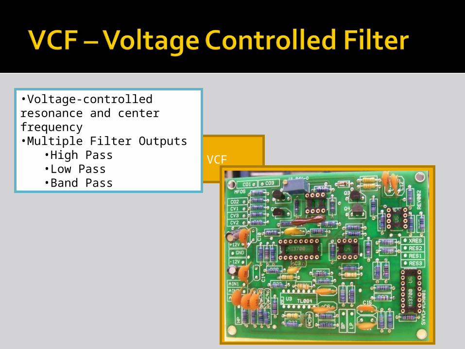
VCF
•Voltage-controlled resonance and center frequency•Multiple Filter Outputs
•High Pass•Low Pass•Band Pass
I’m a big picture of the VCF

VCO VCF VCA1
VCA2Noise Output
MIDI Microcontroller
I’m a big picture of the VCA
•Logarithmic control voltage•Single board with two amplifiers•VCA1 is dedicated to filter output•VCA2 is dedicated to noise source•VCA1 output connects to final synthesizer output
VCA1
Intuitive interfaceAnalog feelDigital control
Interface must be readable by microcontroller
Interface must be writable by microcontroller(in order to support preset recall)

Digital rotary encoder read by the microcontroller
LEDs indicate position of knob to user
Display can be reset by microcontroller to indicate new position


P1
P2
P3
P4
SaveSave
Attack
Decay
Sustain
Release
Pulse Width
Resonance
Vibrato
Mode
Modulation
Variance
Center
Volume
Filter
Options
Filter
LPF
BPF
HPF Fixed
Sine
Tri
•Noise•Sine•Saw
•Rect•Tri

MIDI Keyboard
Microcontroller
LED Driver
I2C DAC
…
I2C DAC
…
VCO Control
Filter Resonance
Other Control Voltages
…
LED Driver
…

Demonstration Requirements Will support adjustment of audio
parameters Will support saving and loading of presets Will support MIDI input and produce audio
output
Basically – we will play some groovy music for the class!

Analog Component Level Testing LabView to generate analog test signals Oscilloscopes to verify waveform properties Circuit tuning and analysis by ear
Digital System Testing Logic analyzer for synchronizing digital
signals Serial connection for debug output Internal status LEDs

Analog boards are built but untestedControl board layout not completePart inventory is incomplete

(24 Oct.) Complete control board layout (27 Oct.) Test each analog component
board (31 Oct.) Acquire control board
components (Nov.) Construct control interface board (Nov.) Program microcontrollers (1 Dec.) Design and construct enclosure

Nearly all parts have been receivedVoltage controlled boards have been
constructed (VCO, VCF, VCA, and noise source)
User interface board has been laid out
Working on laying out digital control board and developing microcontroller software


