17
THE POTENTIAL FOR HIGH PRESSURE COMPOSITE PIPING IN THE MINING INDUSTRY A J BUCHAN and W M BANKS COMRO and UNIVERSITY OF STRATHCLYDE

THE POTENTIAL FOR HIGH PRESSURE COMPOSITE PIPING IN THE MINING INDUSTRY
A J BUCHAN and W M BANKS
COMRO and UNIVERSITY OF STRATHCLYDE
INTRODUCTION
THE POTENTIAL FOR HIGH PRESSURE COMPOSITE
PIPING IN THE MINING INDUSTRY
A J BUCHAN * and W M BANKS **
Little use of composite materials has been made in the mining industry, unless wood can be considered a composite! There are, however, numerous areas where composite materials may be applied to produce cost, mass, performance and efficiency benefits.
There are problems, however, with applying composites in the mining industry. The major concern is not technical but human, with most mining personnel having had limited exposure to this group of materials. An understanding of the potential benefits of these materials and their performance in the mining environment will have to be developed and conveyed to senior personnel in the industry before composite materials will be widely accepted. Mining equipment is often subjected to extremely rough treatment, with corrosion, impact and abrasion playing major roles in damage to components. The corrosion resistance exhibited by many composite materials is one of the most important properties that can be utilized extensively in the mining industry.
This paper is aimed at examining the potential of one application for composite materials in mining namely piping, and considering the problems and benefits that would result.
Piping systems can be considered as the arteries of mines. They are used to convey air for drilling and ventilation, water for cooling, cleaning and powering equipment, slurries for backfill support systems and for removing excess mud and water. The major problem with most piping systems is corrosion and hence any material which can decrease or eliminate corrosion could have extensive applications. Glass fibre reinforced polymers (GRP) have an excellent corrosion resistance and thus have been investigated for their potential in mine piping applications. Although GRP has numerous potential piping applications, this paper considers pressure piping only.
REVIEW OF EXISTING PIPING MATERIALS
The great majority of piping used in mines is of the "mild steel" or carbon steel type, either welded or seamless with various forms of corrosion protection applied to it. Pressure piping is usually seamless and often manufactured from the A 106 Grade B, carbon steel, a 30% carbon and 6% manganese steel which is easy to cut, shape, bend and weld, and is relatively cheap. It has high ductility and fracture toughness, which give it good damage tolerance. However, because of its low corrosion resistance, this
HIGH PRESSURE COMPOSIIE PIPING FOR MINING * - COMRO, PO Box 91230, Auckland Park, Johannesburg, 2006. ** - University of Strathclyde, 75 Montrose St., Glasgow.
type of material is subject to large decreases in wall thickness, both due to internal and external corrosion. In many applications the external corrosion may in fact be worse than that encountered in the bore of the pipe.
There are two fairly recent applications for pressure piping that require large quantities of piping and are set to use even more in the future; these are water hydraulic power, of which hydropower is a major part, and backfill slurry transport.
Water Hydraulic Power
Water hydraulic power is essentially the use of high pressure water to power mining equipment rather than compressed air or electricity. This may be limited to areas of the mining operation such as hydraulic rockdrills and water jetting guns, or for stoping where rockdrills, scraper winch motors, blast hole cleaners, jetting guns for cleaning and fans are all water-powered.
Hydro-power exploits the difference in elevation between the surface and underground workings of a mine to generate an underground supply of water at high pressure (1). This water which is chilled on surface is then reticulated to the mining areas where it is used for powering stoping equipment, cooling and dust suppression. This cooling is necessary as the virgin rock temperature can be as high as fifty to sixty degrees Celsius. By using a continuous column from the surface to the working levels, pressures of the order of 20 MPa can be produced. Figure 1 shows the basic reticulation systems in a hydro-power installation.
Alternatively high pressure water or water-based emulsion may be generated by electrically-driven pumps. Electro-hydraulic power, is a method that can be used where a mine is not deep enough to obtain the required pressure or where limited quantities of high pressure water are to be used. Figure 2 illustrates the general layout of an electro-hydraulically powered mine. This ml~thod of powering has been used for hydraulic rockdrills that run on water and oil emulsions.
At present one pilot hydro-power scheme has been operatIng at a gold mine since 1984 and now a major new mine is being developed that will be purely water-powered. The piping used in these applications is of the carbon steel type.
In designing piping for these high pressure applications, a substantial corrosion allowance has to be included in the pipe wall thickness. In one case the corrosion allowance used is 3 mm for piping required to have a working life of 25 years. There is obviously a substantial cost increase owing to this additional thickness. A further disadvantage of carbon steel piping is that due to the build up of corrosion products in the bore of the pipe, there is an increase in frictional losses with time. This is due both to the decrease of the pipe bore and the increase in
HIGH PRESSURE COMPOSITE PIPING FOR MINING 2

surface roughness. The roughening of the bore due to corrosion increases the rate at which scaling takes place. This also leads to a decrease in the bore of the pipe as the scale thickness increases. All this results in increasing pressure losses and decreased system performance. In the pilot hydro~power scheme operating at a mine on the Far West Rand, substantial increases in pressure losses have been noted over a period of five years.
One design solution to the problem of increasing pressure losses, is to design on the final or "end" surface roughness and final bore of the pipes, and thus to install pipes that are considerably oversized for the first part of their working life. Another solution to the problem is to clean the bore of the pipes, possibly using a pigging method. Other methods are the use of corrosion-resistant materials to replace carbon steel, or coatings such as hot-dip galvanizing on carbon steel.
There are many stainless steels and corrosion-resistant steels available, such as the well-known materials - AISI 304L, AISI 316L and 3CR12. These all have very low general corrosion rates, although they may be susceptible to pitting and crevice corrosion in mine waters. There is also a substantial cost increase when considering replacement of carbon steel with these chromium -containing steels, as these groups of materials typically cost 3 to 6 times more than carbon steel.
Backfill
The use of waste material to fill and thus support the worked-out areas in gold mines has increased tremendously from approximately 10 000 tonnes/month of backfill placed in pilot scale operations in 1980, to 250 000 tonnes/month placed in 1989 (2). The technology in its present form may not be fully mature, but it has tremendous benefits when properly applied. Areas where the rock is too highly stressed to be mined safely using conventional support systems can often be mined using backfilling. By filling in the worked-out areas the cooling requirements of the mine are decreased. This becomes more and more important as mines go deeper and the rock temperature increases.
A typical backfill piping system is shown in Figure 3. There are various different approaches being developed regarding the actual design and operation of backfill systems, but at present the material most used for backfill piping is carbon steel. Severe wear problems have been encountered in systems where the slurry "free falls" in the vertical pipe going down the mine shaft. The actual behaviour of the slurry in this "free fall" region of the piping system is not properly understood but numerous failures do occur in these areas as pipes become perforated by either rounded holes or long slits. Various approaches to this problem are being tried at present, these include lining the pipes with a wearresistant material such as polyurethane or designing th!3 system is such a way as to ensure that the pipes are kept full of slurry
HIGH PRESSURE COMPOSITE PIPING FOR MINING 3
at all times, thus eliminating the free fall zone. This type of design is known as a "full flow system" (3). In the event of a pipe blockage this system gives rise to very high internal pressures in the pipe at the bottom of the shaft, as high as 35 MPa under static conditions in a typical pipe column 2 000 m long.
Corrosion, both internally and externally, plays an important role in the loss of material from the pipe wall and in fact the "wear rate" is a combination of erosion due to the slurry and corrosion due to the water used to make up the slurry.
Many materials are under consideration at the moment to replace carbon steel piping for backfill applications. These fall into the following groups:
- hardened carbon steels - corrosion/abrasion resistant steels - stainless steels - polymers - ceramics - resin/ceramic composites.
In low pressure applications, high-density polyethylene piping (HDPE) has been successfully used for slurry transport underground. Wear rates appear to be low and the ease of handling has produced a favourable response from users. For higher pressure applications, polymers such a high-density polyethylene and polyurethane can be used as wear-resistant liners inside the pipe. In fact, at an Orange Free State mine, polyurethane lining has been used in the free fall zone with initial indications of better results than with unlined steel pipe.
Hardened steels have proved to be an improvement over carbon steel, however, the extent of their performance improvement is limited by the corrosivity of the slurries being transported. Corrosion/abrasion-resistant steels appear to have great promise since they attack both areas of the wear problem encountered in backfill piping.
Stainless steels show a good improvement in performance over carbon steels, however their cost may preclude their use, either on the base of cost/life or on the very high initial capital outlay required.
Ceramics are very wear-resistant and chemically highly inert. However, they are heavy, brittle and expensive. They may find applications in areas of very high wear but are probably unlikely to be used generally in backfill piping. Resin/ceramic bead mixes used as liners have shown good wear resistance and excellent corrosion resistance. They would however be used as liners only.
HIGH PRESSURE COMPOSITE PIPING FOR MINING 4

General Piping Materials
In water transport, where pressures are too high for unreinforced polymer piping, the following materials can be considered:
- mild/carbon steels - hot-dip galvanized steel - corrosion resistant steels (eg 3CR12) - stainless steels (eg AISI 304L and AISI 316L) - coated steels
The carbon steels have already been discussed with regard to their corrosion problems. With welded carbon steel piping there is the additional problem of preferential corrosion along the weld unless the pipe has been normalized after manufacture.
Hot-dip galvanizing (HDG) is extensively used to provide corrosion protection for steels in the mining industry with varying degrees of success. Where the environment is suitable this protection performs well, however, in areas where the pH of mine water falls below 6, the life of the HDG coating is substantially reduced. Problems with HDG coatings in the bore of pipes can frequently be traced to poor water quality control. Control of the external environment is even more difficult, since water emanating from fissures in the rock may have very low pH values due to oxidized pyrites. This leads to a rapid dissolution of the HDG layer and hence a loss of corrosion protection for the steel substrate.
Corrosion-resistant and stainless steels have successful applications, but also must be selected with due regard to the particular environment where they are to be employed. Problems experienced with these materials include pitting and crevice corrosion and preferential attack of weldments. Their major drawback though, is their high cost compared with carbon steel piping.
Coated steels can perform very well, but poor application of coatings or in service damage to the coating allows normal corrosion of the steel to take place. Damage to the coating due to abrasion or impact is highly likely in a mining environment.
Summary of Presently-Used Piping Materials
Corrosion is the major problem with most mine piping and occurs internally, externally or both.
Corrosion combines with erosion in backfill slurry transport systems to cause increased wear rates.
Corrosion increases costs in carbon steel piping systems due to increased wall thicknesses from the addition of corrosion allowances, decreased system efficiency due to increasing frictional losses and replacement costs due to pipe failures.
HIGH PRESSURE COMPOSITE PIPING FOR MINING 5
POTENTIAL GRP PIPING APPLICATIONS
The previous section has demonstrated that corrosion is the major problem in the use of carbon steel piping, thus there is potential for corrosion-resistant materials wherever carbon steel piping is used. Where erosion by slurries is involved, wear resistance is required along with corrosion resistance. Specific potential applications for GRP piping are given in the following sections with some performance requirements.
Water Hydraulic Power
In this application, the major requirements are:
the ability to safely contain chilled water at working pressures of up to 25 MPa to design pipe lives of up to 25 years
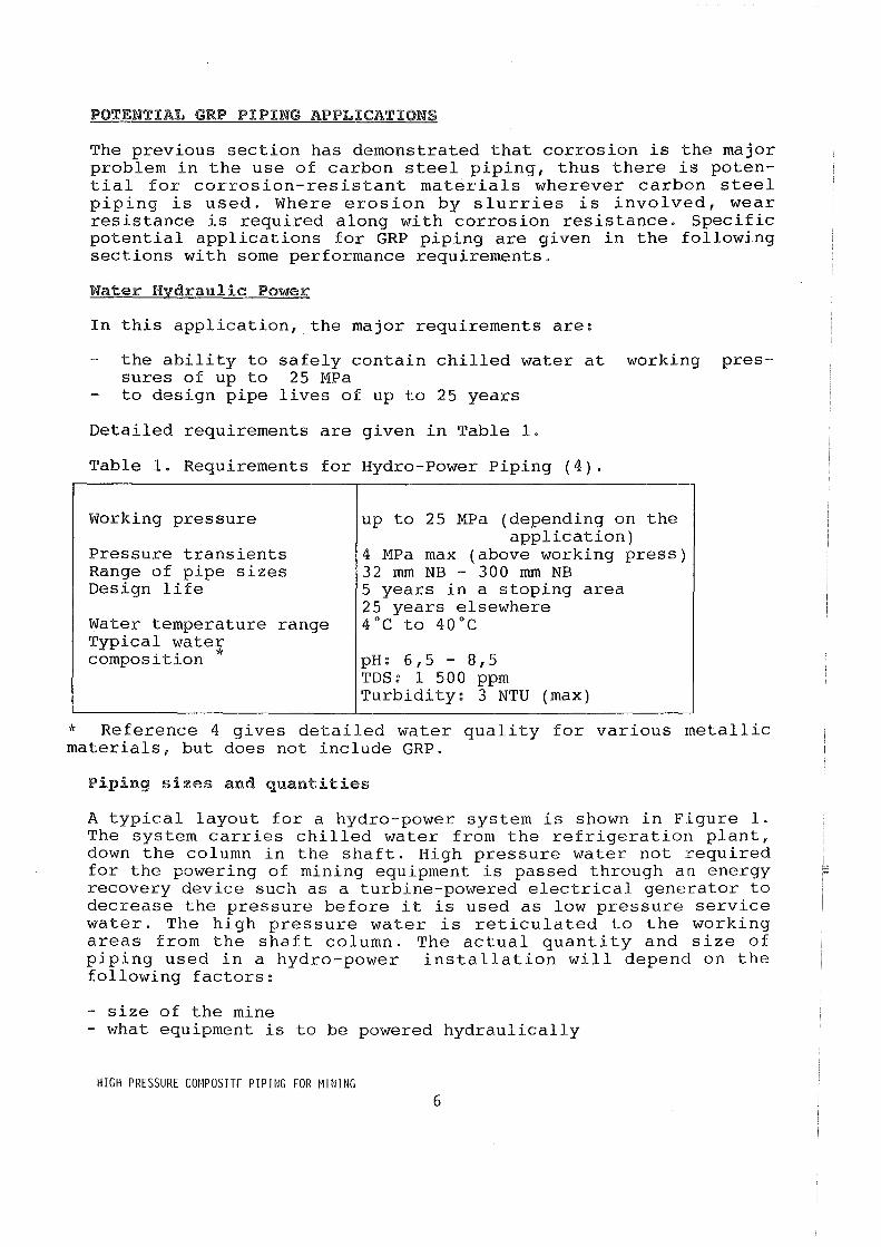
Detailed requirements are given in Table 1.
Table 1. Requirements for Hydro-Power Piping (4).
Working pressure
Pressure transients Range of pipe sizes Design life
Water temperature range Typical water .. * composltlon
up to 25 MPa (depending on the application)
4 MPa max (above working press) 32 mm NB - 300 mm NB 5 years in a stoping area 25 years elsewhere 4°C to 40°C
pH: 6,5 - 8,5 TDS: 1 500 ppm Turbidity: 3 NTU (max)
* Reference 4 gives detailed water quality for various metallic materials, but does not include GRP.
Piping sizes and quantities
A typical layout for a hydro-power system is shown in Figure 1. The system carries chilled water from the refrigeration plant, down the column in the shaft. High pressure water not required for the powering of mining equipment is passed through an energy recovery device such as a turbine-powered electrical generator to decrease the pressure before it is used as low pressure service water. The high pressure water is reticulated to the working areas from the shaft column. The actual quantity and size of piping used in a hydro-power installation will depend on the following factors:
- size of the mine - what equipment is to be powered hydraulically
HIGH PRESSURE COMPOSITE PIPING FOR MINING 6
- method of mining used
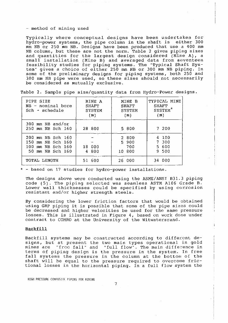
Typically where conceptual designs have been undertaken for hydro-power systems, the pipe column in the shaft is either 300 mm NB or 250 mm NB. Designs have been produced that use a 400 mm NB column, but these are not the norm. Table 2 gives piping sizes and quantities for the largest design considered (Mine A), a small installation (Mine B) and averaged data from seventeen feasibility studies for piping systems. The "Typical Shaft System" gives a choice of either 250 mm NB or 300 mm NB piping. In some of the preliminary designs for piping systems, both 250 and 300 mm NB pipe were used, so these sizes should not nec(~ssarily be considered as mutually exclusive.
Table 2. Sample pipe size/quantity data from Hydro-Power designs.
PIPE SIZE MINE A MINE B TYPICAL MINE NB - nominal bore SHAFT SHAFT SHAFT Sch - schedule SYSTEM SYSTEM SYSTEM*
( m) (m) (m)
300 mm NB and/or 250 mm NB Sch 160 28 800 5 800 7 200
200 mm NB Sch 160 - 2 800 4 100 150 mm NB Sch 160 - 5 900 7 300 100 mm NB Sch 160 18 000 700 5 600
50 mm NB Sch 160 4 800 10 800 9 500
TOTAL LENGTH 51 600 26 000 34 000
* - based on 17 studies for hydro-power installations.
The designs above were conducted using the ASME/ANSI B31.3 piping code (5). The piping selected was seamless ASTM AI06 Grade B. Lower wall thicknesses could be specified by using corrosion resistant and/or higher strength steels.
By considering the lower friction factors that would be obtained using GRP piping it is possible that some of the pipe sizes could be decreased and higher velocities be used for the same pressure losses. This is illustrated in Figure 4, based on work done under contract to COMRO at the University of the Witwatersrand.
Backfill
Backfill systems may be constructed according to different designs, but at present the two main types operational in gold mines are "free fall" and "full flow". The main diffe:cence in terms of piping design is the pressure in the system. In free fall systems the pressure in the column at the bottom of the shaft will be equal to the pressure required to overcome frictional losses in the horizontal piping. In a full flow system the
HIGH PRESSURE COMPOSITE PIPING FOR MINING 7

working pressure at the bottom of the column will depend on the depth of the system. In three typical systems, described in Table 3, pressures have been calculated under flow conditions and in the event of pipe blockage.
Table 3. Pressures in a sample of backfill systems (6).
DETAILS SYSTEM A SYSTEM A SYSTEM B (free fall) (full flow) (full flow)
column depth 2 200 m 2 200 m 1 425 m slurry rel.density 1,7 1,7 1,7 pipe nominal bore 50 mm 50 mm 50 mm pipe schedule Sch. 80 Sch. 80 Sch. 80 dynamic pressure 8,5 MPa 21 MPa 14 MPa static pressure 37 MPa 37 MPa 25 MPa (blocked pipe)
Even though corrosion is a very important factor as was discussed previously, wear resistance is vital. Some form of wear-resistant liner will be required for GRP backfill piping. Ideally there should also be some way to monitor the thickness of the wear liner, so that pipes could be changed before the wall thickness reaches the minimum safe dimension. Obviously it would be important to ensure that no damage to the structural part of the pipe (namely the GRP) would occur. This is especially true of the full flow type of backfill system where pressures are of a level to be dangerous in the event of a pipe burst. Although it may prove to be preferable to use steel piping in the areas of a full flow system where the pressures are highest, the other areas where pressures are lower may be made up with GRP piping.
Piping sizes and quantities
Typically, backfill pipe ranges are three to five thousand metres long. The pipes used are generally 50 mm nominal bore, schedule 80, with some mines using 65, 80 and 100 mm nominal bore pipe. In higher pressure areas, for example, in full flow systems, or where severe wear problems occur, very thick Schedule XXS piping is used. Some mines use high density polyethylene in the horizontal portion of the pipeline underground, and this may account for up to two thousand metres of piping.
In 1989, according to COMRO estimates, there were eighty-four backfill systems installed in the gold mining industry, with plans in 1990 to expand this number to over one hundred and twenty.
HIGH PRESSURE COMPOSITE PIPING FOR MINING 8

DESIGN CONSIDERATIONS
Design Philosophy
In considering the application of GRP piping to high pressure mining piping it was decided that the only realistic approach to the design was to adopt a systems approach. Individual items cannot be considered in isolation, and thus the interaction of the components in a piping system, the mining operation, and even the mine itself must be considered. This is especially important since no GRP application of this type exists at present from which experience can be obtained. The nearest applications are perhaps in the North American oil industry where high pressure GRP piping has been in use for over 25 years.
Standards and Specifications
Initial work centered around obtaining a piping code or standard that would be applicable to the designs considered or which could at least be adapted. This is especially important as the mining industry tends to work to closely defined standards and standard procedures. In the design of high pressure piping systems in steel, the ASME/ANSI B31.3 code (5) has been used extensively, however this is not applicable to GRP piping.
The new British Standard BS 7159:1989 (7) covering the design and construction of GRP piping systems for individual plants or sites was considered. This, however, is limited in its range of pressure, which is 1 MPa for pipes up to 600 mm internal d.Lamet,er. This code is also strain-based as opposed to the American codes that are stress-based.
BS 5480 Parts 1 and 2 (8,9) contains information regarding both pressure and non-pressure pipe for water or sewerage. The highest working pressures considered in this standard are 6,4 MPa.
BS 6464 -1984 (10) is not applicable for piping "where the product of the design pressure in bar and the nominal diameter in millimetres is more than 11,000". Thus it would cover 50 mm piping up to 22 MPa, but not the larger pipe sizes.
The American Petroleum Institute has produced a specification for high pressure glass fibre reinforced line pipe (API 15HR, 1988) (11), which is applicable for the pressures considered. API 15HR is for high pressure line pipe with pressure ratings greater than 7 MPa. It is based on the following service conditions:
20 year service life - service temperature 66°C - salt water fluid - 3000 cyclic pressure variations from 0 to 120% of the pressure
rating.
HIGH PRESSURE COMPOSITE PIPING FOR MINING 9
This specification makes extensive use of ASTM standards for the testing of pipe and obtaining design data for pipe and fittings. The relevant standards are the following:
ASTM D2992-71 (reapproved 1977), entitled "Standard method for obtaining hydrostatic design basis for reinforced thermosetting resin pipe and fittings". The only limitations on this standard being a minimum outside diameter to wall thickness ratio of 10 and any "practical" temperature. The standard gives two methods of obtaining the Long Term Hydrostatic Strength (LTHS) used for deriving the hydrostatic design stress. The first method entails the testing of a minimum of eighteen specimens to obtain failure stress against time for periods of up to 10 000 hours. The curve obtained from this data is then extrapolated on a logarithmic scale to 100 000 hours (approximately 11,5 years) as shown in Figure 5. In discussions with personnel involved in the design and production of high pressure GRP piping, it was stated that in practice this value of 11,5 years can be multiplied by approximately 2, which gives the required design life of 25 years for hydro-power systems. (Note API 15HR is based on a 20 year design life). The other' method of obtaining the LTHS value is based on obtaining failure stress versus number of pressure cycles, up to fifteen million cycles and extrapolating this on a log scale to 150 million cycles as shown in Figure 6. Since the cycling is carried out at 25 cycles/minute, 150 million cycles approximates to 11,5 years.
This high level of cycling is not likely to occur in a hydropower installation where the major stress cycles are not likely to amount to more than 14 000 during the systems working life. The situation for backfill systems is probably the same although this is still subject to some doubt.
Other ASTM test procedures that are relevant to the testing of GRP pipe are only listed below and not discussed as many of the readers may be familiar with them.
- ASTM 0 1598 - 86, Standard test method for time-to-failure of plastic pipe under constant internal pressure.
ASTM D 1599 -86, Standard test method for short-time hydraulic failure pressure of plastic pipe, tubing and fittings.
ASTM D 2143 - 69 (reapproved 1976), Standard test method for cyclic pressure strength of reinforced, thermosetting plastic pipe.
Thus, from the examination of available standards and discussions with GRP piping manufacturers, it appears that the API 15HR specification with the relevant ASTM test methods would be applicable to the high pressure piping considered. BS 7159 is useful as a guide only, for system design. There is also extensive "in-house" knowledge with some of the piping manufacturers,
HIGH PRESSURE COMPOSITE PIPING FOR MINING 10
but this is not generally available.
Construction method
Due to the high specific strength requirements for high pressure piping, filament-wound pipe has been considered as the method of construction. There is also the possibility of using a combination of filament winding and pultrusion which would probably allow a decrease in wall thickness, due to higher glass contents achievable with this method
Failure considerations
In lengthy discussions with recognized manufacturers of high pressure piping, it has been established that for low pressure GRP piping a safety factor of 4 on burst pressure is normal. However, for pressures above 5 MPa and certainly for pressures of the order of 20 MPa, it was felt that a safety factor of 4 would be impractical. The manufacturers were of the opinion that safety factors in the range 2 to 2,5 were suitable. Especially since piping produced to API specifications would be subjected to fairly stringent quality assurance procedures.
Likely modes of failure need to be examined in considering safety factors. If unlined filament-wound pipe is used, it is unlikely to fail catastrophically except in the event of a major rock fall. The mode of failure is likely to be that of weeping through cracks in the resin matrix, and hence a safety factor as discussed above would be applicable. However, in the event of a liner being used the failure mode may change. One liner method proposed is to overwind a thermoplastic liner with GRP. This would prevent any ingress of water into the laminate through cracks in the resin. The drawback with this is that a liner of this type would act as a seal until the ultimate strength of the pipe wall was exceeded and a burst-type failure with no or little warning could occur. Alternatively a filament-wound linl~r could be used and then a weep-type failure would be the likely failure mode.
Long term performance
Long term performance tests of GRP piping in an oilfield application has been reported by Oswald (12), in which tests w(~re performed on pipe removed from service over the period 1962-1987. It was found that the data obtained did fit the regression lines obtained for the original pipe form ASTM 02143. The material in question was an epoxy/glass composite, used at working pressures of approximately 0,5 MPa. One interesting conclusion was that the mode of failure in pressure tests changed with time. Originally the failure mode in the unlined pipe was by pipe wall weeping. After 25 years however, "the burst test specimens failed by major pipe-wall fracture", indicating that the laminate had been af-
HIGH PRESSURE COMPOSITE PIPING FOR MINING 11

fected by the 25 years service.
Joining methods
One major manufacturer of GRP piping produces a range of high pressure (20 MPa) line pipe up to 80 mm nominal bore, with API Standard 5B threads for-joining pipe. Pipes up to 150 mm nominal bore are produced using this joining method, although wi-th lower pressure ratings. It is felt that API threads could be applied to most piping, with testing being required for the larger pipe sizes.
It is suggested, however, that a form of the "keylock" system (see Figure 7) be seriously considered for jointing in mining applications. An advantage is that it is very easy to assemble piping systems with this jointing method. But the availability of suitable hardware in GRP is limited and it is likely that some further development and testing would be necessary.
Damage tolerance
All mining equipment is subjected to harsh treatment. One of the major concerns with GRP piping is its low resistance to impact damage compared with steel. This will need to be a major area of evaluation for any GRP piping system.
Fire Hazards
Smoke and toxic gas emissions from burning or smouldering materials will be even more closely controlled in the future with increasing concern about fire hazards. At present two of the major mining houses have rejected the use of polyester resins without fire retardants underground. There is also concern about many fire retardants since they either give off halogen tJases or gases involving poisonous metals such as antimony. In addition, the decrease in mechanical properties with the addition of retardants would almost certainly rule out such treated resins for high pressure piping applications. For this reason it appears that phenolics are at present the likely resin group for GRP piping underground. Forsdyke (13) examined tests performed by a number of different bodies considering the use of phenolic resins and found that phenolics passed the tests for all potential applications. These applications included naval, railway rolling stock, buses and public buildings.
There is the possibility of overwinding polyester-based laminates with phenolic resin, although this would have to undergo fire testing before it would be readily accepted underground.
COSTS
In considering GRP piping, it must be able to compete with con-
HIGH PRESSURE COMPOSITE PIPING FOR MINING 12
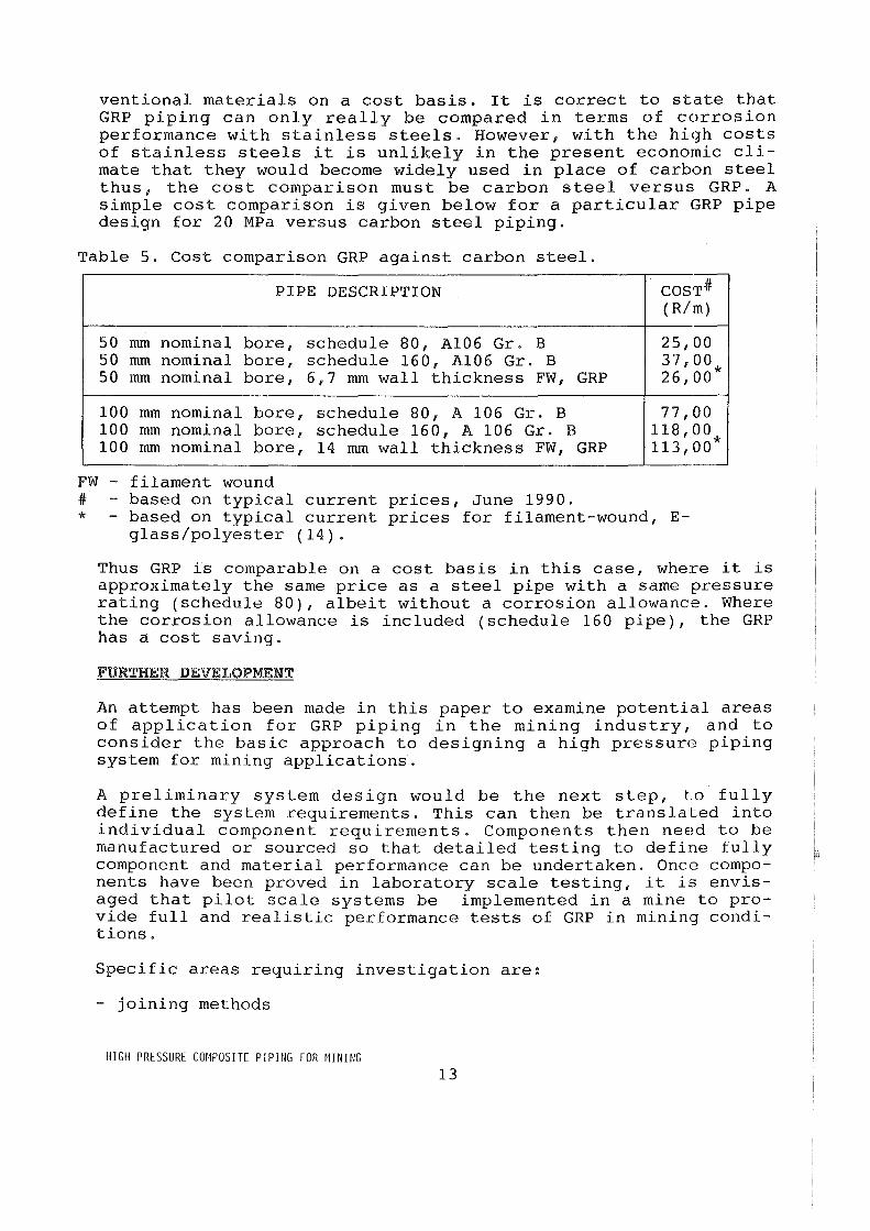
ventional materials on a cost basis. It is correct to state that GRP piping can only really be compared in terms of corrosion performance with stainless steels. However, with the high costs of stainless steels it is unlikely in the present economic climate that they would become widely used in place of carbon steel thus, the cost comparison must be carbon steel versus GRP. A simple cost comparison is given below for a particular GRP pipe design for 20 MPa versus carbon steel piping.
Table 5. Cost comparison GRP against carbon steel.
PIPE DESCRIPTION COST# (R/m)
50 mm nominal bore, schedule 80, A106 Gr. B 25,00 50 mm nominal bore, schedule 160, A106 Gr. B 37,00 50 mm nominal bore, 6,7 mm wall thickness FW, GRP 26,00*
100 mm nominal bore, schedule 80, A 106 Gr. B 77,00 100 mm nominal bore, schedule 160, A 106 Gr. B 118,00 100 mm nominal bore, 14 mm wall thickness FW, GRP 113,00*
FW - filament wound # based on typical current prices, June 1990. * - based on typical current prices for filament-wound, E
glass/polyester (14).
Thus GRP is comparable on a cost basis in this case, where it is approximately the same price as a steel pipe with a same pressure rating (schedule 80), albeit without a corrosion allowance. Where the corrosion allowance is included (schedule 160 pipe), the GRP has a cost saving.
FURTHER DEVELOPMENT
An attempt has been made in this paper to examine potential areas of application for GRP piping in the mining industry, and to consider the basic approach to designing a high pressur!~ piping system for mining applications.
A preliminary system design would be the next step, to fully define the system requirements. This can then be translated into individual component requirements. Components then need to be manufactured or sourced so that detailed testing to define fully component and material performance can be undertaken. Once components have been proved in laboratory scale testing, it i3 envisaged that pilot scale systems be implemented in a mine to provide full and realistic performance tests of GRP in mining conditions.
Specific areas requiring investigation are:
- joining methods
HIGH PRESSURE COMPOSITE PIPING FOR MINING 13

- fire performance - impact resistance - long term properties. - non-destructive examination (NDE) techniques
Joining
The proposals discussed earlier to use either a "keylock" type system or API threads, needs to be experimentally investigated, especially in larger bore pipes (over 150 mm). Work has been undertaken in other methods of joining such as flanged couplings and these would need to form part of the evaluation. In steel piping it has been felt at COMRO that joining methods should produce a joint at least as strong in bending as the pipe itself. This has been borne out in practice when a length of a hydropower pipe line was involved in a major fall of ground, and since the connectors were at least as strong as the pipe, no leaks occurred and the system was still operational and safe.
Fire performance
Comprehensive fire testing of components will be required, especially in view of the great concern with fire safety within the mining industry at present. COMRO has extensive experience in this area and has a dedicated full scale test facility. The fire testing would be aimed at determining mechanical performance of components under fire conditions, as well as smoke and noxious gases emissions.
Impact resistance
This is an area where GRP is at a disadvantage to carbon steel. Requirements for impact resistance will have to be defined and components evaluated against these, to ensure components are able to function adequately under mining conditions.
Long term properties
Investigation of long term properties in mining conditions will be necessary before final designs for high pressure piping systems in GRP can be performed.
NDE techniques
Any material used for potentially dangerous applications must be capable of being monitored. Appropriate monitoring techniques and procedures will need to be investigated and put into practice.
INTRODUCING GRP PIPING INTO MINES
With the limited exposure that the mining industry has had to composite materials, it is unlikely, even with proper design and
HIGH PRESSURE COMPOSITE PIPING FOR MINING 14

on surface testing, that GRP piping would be accepted immediately on many mines. It is suggested that one approach would be to introduce low pressure GRP piping for trial into existing piping systems, where any failure would not be dangerous. This would allow an understanding of the materials behaviour to be developed and solutions to any shortcomings to be devised. Low pressure piping is a market on its own and would serve to introduce the material into the industry while the necessary work is carried out on high pressure GRP piping.
CONCLUSIONS
Initial studies suggest that high pressure GRP piping is feasible in the applications considered and would have benefits for the mining industry.
There are standards and codes available that will give considerable help in the design and testing of the required systems.
- Considerable quantities of piping are going to be consumed in medium and high pressure applications in the mining industry in the future.
GRP's tremendous advantage of corrosion resistance makes it attractive as a piping material across the complete pressure range.
Backfill piping is one of the potential applications for GRP if used with a suitable wear resistant liner.
Considerable work will be required in developing GRP piping systems to the implementation stage for high pressure applications (20 MPa plus).
The very smooth bores obtainable with GRP piping will lead to lower pressure losses in piping systems or conversE!ly will allow greater flow capacity for a particular size pipe.
Low pressure piping is an area where GRP can be introduced to the mining industry in the short term.
There are a number of potential applications for GRP piping in the mining industry due to the excellent corrosion resistance of the material. The three areas of potential application are:
- hydro-power - backfill (with a suitable wear resistant liner) - low pressure water piping
Development and testing is required before high pressure piping systems suitable for mining applications can be considered technically ready.
HIGH PRESSURE COMPOSITE PIPING FOR MINING 15
REFERENCES
1. Du Plessis AG, Wymer DG and Joughin NC, Equipment alternatives for stoping in gold mines, Journal of the South African Institute of Mining and Metallurgy, vol. 89, no. 12, December 1989. 2. Spearing AJS, Objectives, trends and current research into backfilling on Witwatersrand gold mines, Slurry Transport in the mining industry, Hydraulic Conveying Association, Sandton, September 1989. 3. Gericke D, Full flow, free fall and pumping of backfill slurries, Slurry Transport in the Mining Industry, Hydraulic Conveying Association, Sandton, 1989. 4. Water Hydraulic Power Specifications, User Guide No. 19, COMRO, Johannesburg, 1990. 5. ASME/ANSI B31.3 Code for Pressure Piping, 1987 Edition, The American Society of Mechanical Engineers, New York, 1987. 6. Personal communication with TM 0' Brien, Exploitation Technology, COMRO, Johannesburg, 1990. 7. BS 7159:1989, Design and construction of glass reinforced plastics (GRP) piping systems for individual plants or sites. 8. BS 5480:Part 1:1977, Glass fibre reinforced plastics (GRP) pipes and fittings for use in water supply or sewerage, Part 1. Dimensions, materials and classification, British Standards Institution, 1977. 9. BS 5480:Part 2: 1982, Glass fibre reinforced plastics (GRP) pipes and fittings for use for water supply or sewerage, Part 2. Design and performance requirements, British Standards Institution, 1982. 10. BS 6464:1984, Reinforced plastics pipes, fittings and joints for process plants, British Standards Institution, 1984. 11. API Specification 15HR, Specification for high pressure fiberglass line pipe, First Ed., American Petroleum Institute, Washington, Sept. 1988. 12. Oswald KJ, The effect of 25 years of oil field flow line service on epoxy fibreglass pipe, Paper No. 167, Corrosion 88, NACE, St. Louis, 1988. 13. Forsdyke KL, Built-in confidence with phenolic GRP, IMechE conference proceedings, paper C400/021, London, 1990. 14. Personal communication with J Sigalas, CSIR, 1990.
ACKNOWLEDGEMENT
This work forms part of the research programme of COMRO.
HIGH PRESSURE COMPOSITE PIPING FOR MINING 16


