----------------------------------- i i i s s s p p p a a a r r r k k k operating instructions –ThEx-10 ------------------------------ ThEx-10_06.doc ----------------------------------------------------------------------------------------------------- 1 The relation of i i i s s s p p p a a a r r r k k k and ThEx-10 The PTB report ThEx-10 was issued in 1999 as a result of fundamental research work with the intention to give an actual and feasible procedure for evaluation of intrinsically safe circuits where non linear sources take part of. Nowadays this method is acknowledged and reported by EN 50039 and IEC 60079-25 as an annex. This article is added to i i i s s s p p p a a a r r r k k k ’ ’ ’ s s s information package substantially for the following reasons: - the data of ThEx-10 are direct derivatives of i i i s s s p p p a a a r r r k k k - the differences between using i i i s s s p p p a a a r r r k k k and ThEx-10 shall be pointed out - for better understanding the related content of EN 50039 and IEC 60079-25 for some physical insight shall be given - the diagrams are reported here as an electronic paper; they can easily be printed out whenever needed and be worked with on computer’s desktop and comprises diagrams for L = 0.01 mH, while the standards will not
The relation of iiissspppaaarrrkkk and ThEx-10 The PTB report ThEx-10 was issued in 1999 as a result of fundamental research work with the intention to give an actual and feasible procedure for evaluation of intrinsically safe circuits where non linear sources take part of.
Nowadays this method is acknowledged and reported by EN 50039 and IEC 60079-25 as an annex.
This article is added to iiissspppaaarrrkkk’’’sss information package substantially for the following reasons:
- the data of ThEx-10 are direct derivatives of iiissspppaaarrrkkk
- the differences between using iiissspppaaarrrkkk and ThEx-10 shall be pointed out
- for better understanding the related content of EN 50039 and IEC 60079-25 for some physical insight shall be given
- the diagrams are reported here as an electronic paper; they can easily be printed out whenever needed and be worked with on computer’s desktop and comprises diagrams for L = 0.01 mH, while the standards will not
Ignition data reported in standards concerning intrinsically safe apparatus like EN 50020 and IEC 60079-11 as tables, diagrams or even simple energy values refer to very simple circuits only:
- the data of the capacitive limit are researched using a very high feeding resistor of 100 kΩ only
- the inductive limits were determined at 24 V only and there are some hints for the use of even lower volt-ages in the vicinity of the ohmic boundary
- only circuits using resistive limitation are reported (linear characteristic)
Because of it’s physically orientated design, ThEx-10 does not suffer from these restrictions. One may imagine standard’s data to be special examples out of which characteristic parameters can be extracted and ThEx-10 represents an over all sort of inter-/extrapolation. A lot of other ignition data, especially those developped in PTB were incorporated additionally, contributing to its validity.
Especially in situations where big lumped capacitances and inductances are present simultaneously it would be hazardeous to neglect the possible transformation of capacitively stored energy to an inductively released one. ThEx-10 solves this problem as well as circuit’s non linear properties.
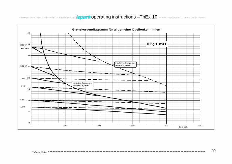
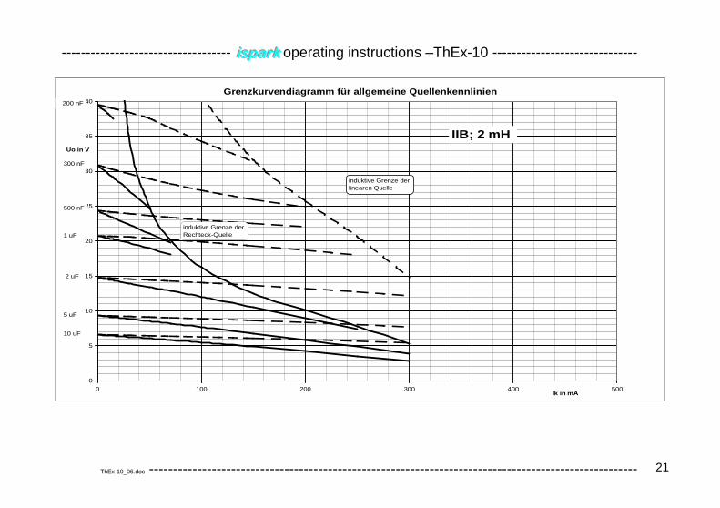
Working with the diagrams of ThEx-10 takes for granted, that the effective source characteristic is known. The wording effective means interconnection properties, failure assumptions and dynamic behaviour are taken into account. Results are pairs of combined permissible capacitances and inductances.
The appropriate way to use the diagrams is to draw the actual source into the ‚naked’ diagram form copied on a transparency. Additionally drawn lines in parallel with the diagram’s axis’ are necessary intersecting them at the maximum source voltage resp. current.
This transparency then is used as an overlay with respect to the diagrams, each of them characterized by gas-group and inductance.
The conditions for intrinsic safety are:
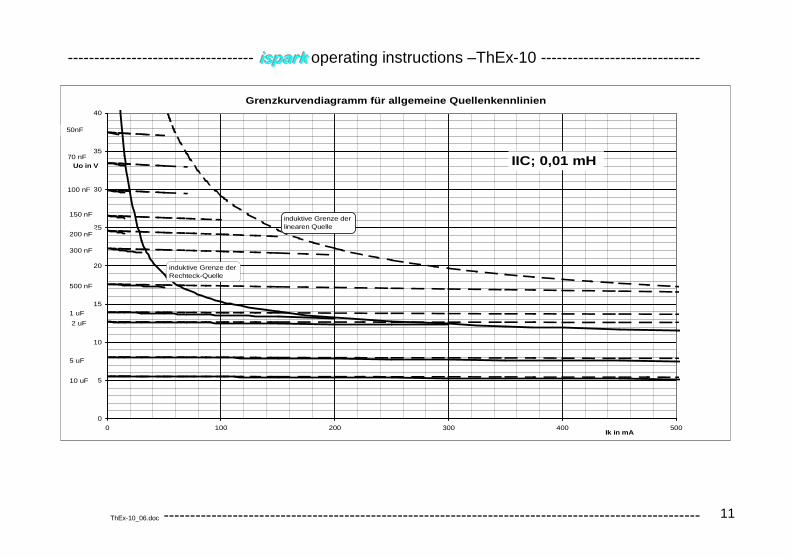
A the (original) source characteristic’s curve must not exceed the line representing the limit with respect to rectangular sources (solid hyperbolic line)
B the extrapolated point resulting out of maximum voltage and current shall not be beyond the line for linear sources (dashed hyperbolic line)
All diagrams, these conditions are fulfilled within, may be a basis for determining the associated maximum permis-sible capacitance. For this purpose the two different sets of curves for capacitance have to be considered; dashed ones to be compared with the extrapolated point mentioned as B above and solid ones not to be exceeded at any point by the curve according to A. Suitable interpolation is allowed.
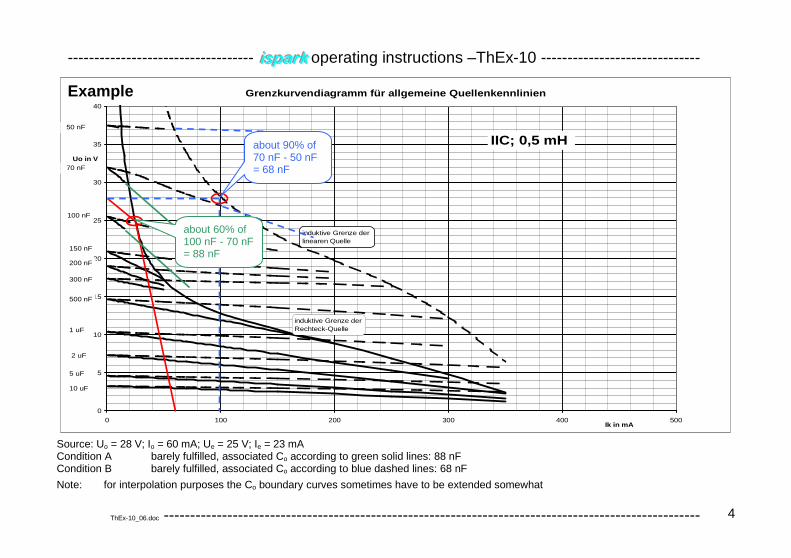
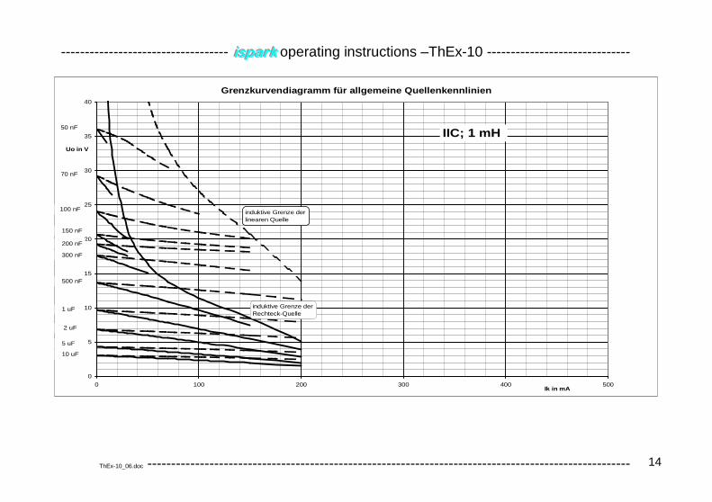
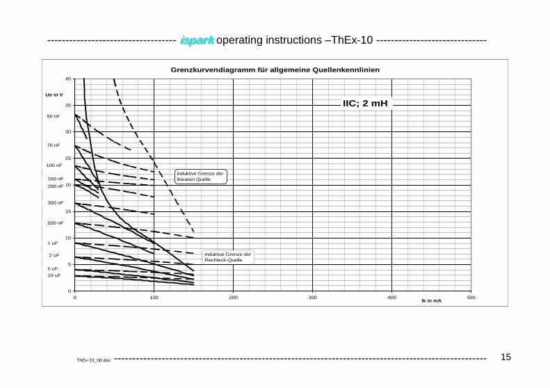
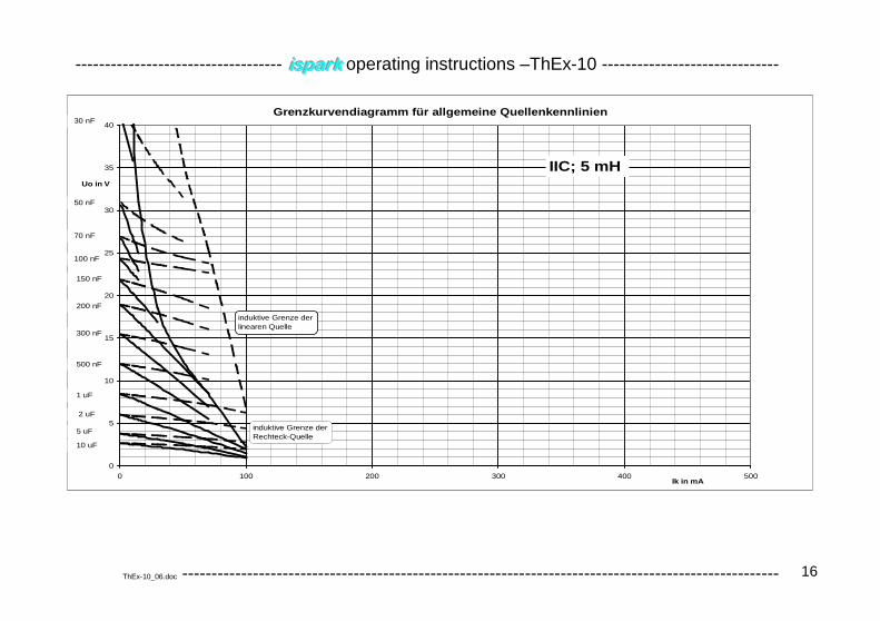
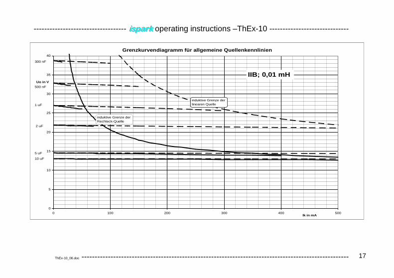
Grenzkurvendiagramm für allgemeine Quellenkennlinie n
0
5
10
15
20
25
30
35
40
0 100 200 300 400 500Ik in mA
Uo in V
IIC; 0,5 mH
100 nF
150 nF
200 nF
300 nF
2 uF
5 uF
1 uF
10 uF
induktive Grenze derlinearen Quelle
induktive Grenze derRechteck-Quelle
500 nF
70 nF
50 nF
about 90% of 70 nF - 50 nF = 68 nF
about 60% of 100 nF - 70 nF = 88 nF
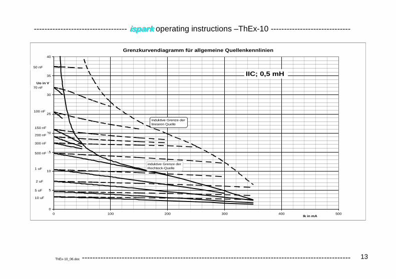
Example
Source: Uo = 28 V; Io = 60 mA; Ue = 25 V; Ie = 23 mA Condition A barely fulfilled, associated Co according to green solid lines: 88 nF Condition B barely fulfilled, associated Co according to blue dashed lines: 68 nF
Note: for interpolation purposes the Co boundary curves sometimes have to be extended somewhat
The finally resulting permissible capacitance is the minor one of both (68 nF here); it’s provisionally valid in con-junction with the associated inductance of the actually used diagram.
The next step is to check, that the evaluated capacitance complies also with all diagrams representing smaller in-ductances within the same gasgroup. Normally, but not always this check is passed (here it is). The smallest evalu-ated capacitance is valid for declaring electrical data for the circuit under consideration.
Note: While this ThEx-10 evaluation results in 0.5 mH and 0.068 µF, iiissspppaaarrrkkk will assess this circuit to have a safety factor of 1.32 with spark type o-0C only. This weakness is due to the simple graphical representation of ThEx-10, not allowing to keep the intended safety factor exactly and the cause for the restriction to use ThEx-10 for category ib and installation practices only.
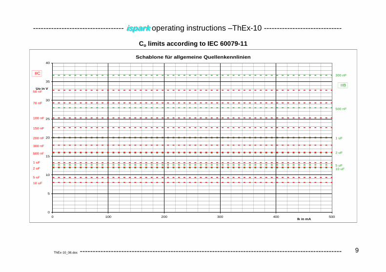
At last must be ensured, that the maximum permissible capacitance according to the relevant standard is not ex-ceeded (ThEx-10 sometimes may allow some greater capacitances than the standard because of its sophisticated application of the required safety factor); please use the overlay foil “Co according to IEC 60079-11”. .
Note: Because the diagrams of ThEx-10 are available here in an electronic form, a comparable procedure as described above can be performed by using a computer without the need of paper or transparencies. Stan-dard software allows to cut and paste the diagrams and to draw the required lines. A great benefit doing so is among others an easy incorporation in subsequent documents.
Comparing competitions of ThEx-10 and iiissspppaaarrrkkk
The benefit of iiissspppaaarrrkkk compared to ThEx-10 mainly is not in scope, but in performance, as a consequence of a necessary reduction to a paper related procedure. It's not restricted to special presented inductances but covers the range from nearly zero to 100 mH and no interpolation manually to be performed is necessary. The most es-sential benefit of iiissspppaaarrrkkk may be yet, that's living and will grow with power in future by inclusion of additional proper-ties, which can't be implemented by a paper related procedure.
On the other hand, ThEx-10 doesn't need any computer or software nor imposes a procedure, whose internals are invisible and hardly known by the user.
The most essential difference is the property of iiissspppaaarrrkkk, to maintain the safety factor 1.5 regardless source’s shape while ThEx-10 may produce results down to a safety factor of about 1.0. Therefore ThEx-10 may be used only with category ib and only for installation purposes.
From a practical point of view iiissspppaaarrrkkk works significantly faster, allowing to investigate more constellations and coming closer to a possible optimum for example while developing an apparatus.
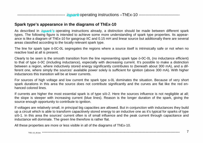
Spark type’s appearance in the diagrams of ThEx-10
As described in iiissspppaaarrrkkk’’’sss operating instructions already, a distinction should be made between different spark types. The following figure is intended to achieve some more understanding of spark type properties. Its appear-ance is like a diagram of ThEx-10 for gasgroup IIC and 0.15 mH and linear source but additionally there are several areas classified according to the locally relevant spark type.
The line for spark type ö-0C-0L segregates the regions where a source itself is intrinsically safe or not when no reactive load at all is present.
Clearly to be seen is the smooth transition from the line representing spark type ö-0C-0L (no inductance efficient) to that of type ö-0C (including inductance), especially with decreasing current. It’s possible to make a distinction between a region, where inductively stored energy significantly contributes to (beneath about 300 mA), and a dif-ferent one, where simply the sources’ available power solely is sufficient for ignition (above 300 mA). With higher inductances this transition will be at lower currents.
For sources of high voltage and low current the spark type s-0L dominates the situation. Because of very short spark durations in this area the source does not contribute significantly and the curves are flat like the red en-hanced colored lines.
If currents are higher the most essential spark is of type s/ö-2. Here the sources influence is not negligible at all; the slope is steeper with increasing current (blue lines). Reason is the longer duration of the spark, giving the source enough opportunity to contribute to ignition.
If voltages are relatively small, in principal big capacities are allowed. But in conjunction with inductances they build up a circuit which is able to transform capacitively stored energy to an inductive one as it’s typical for sparks of type s/ö-1. In this area the sources’ current often is of small influence and the peak current through capacitance and inductance will dominate. The green line therefore is rather flat.
All these properties are more or less visible in all of the diagrams of ThEx-10.