1 Page 1 Equipment and Process Integration Center MDL [email protected]MSM2002 1 The Role of TCAD in Compact Modeling Michael Duane Applied Materials Michael apologizes for not being able to be here today. This talk will discuss how TCAD is used (and not used) in compact modeling. There should be a natural connection between the two groups, but he feels that there actually is a significant barrier -- or at least, there is not as much collaboration as there could be.
Michael apologizes for not being able to be here today.
This talk will discuss how TCAD is used (and not used) incompact modeling. There should be a natural connectionbetween the two groups, but he feels that there actually is asignificant barrier -- or at least, there is not as much collaborationas there could be.
� Review of TCAD� TCAD at Applied Materials� Rev0 models from TCAD� Use of TCAD for compact model development� Future opportunities
Although this audience is probably familiar with what TCAD is, wewill start with a brief discussion of what TCAD can and cannot do.
Then, to answer your question, “Yes, we do use TCAD at AppliedMaterials”, and there a few slides describing that activity.
Next, TCAD can be used for generating pre-silicon, or Rev0models. There are probably some skeptics to this approach inthe audience, so the benefits of simulation-based Rev0 modelswill be presented.
Finally, a brief discussion of how TCAD had not been used muchfor the development of compact models, and a few opportunitiesfor collaboration between TCAD and compact modeling.
� TCAD is process and device simulation. Widely used at ICmanufacturers during technology development; 20+ yearhistory.
� Software examples:– SUPREM, PISCES, PROPHET– Athena and Atlas– TSUPREM4, MEDICI, TAURUS– DIOS and DESSIS– and many others.
The point of this slide is that TCAD is fairly established. In a fewminutes, we will talk about the problems with TCAD. There havebeen dozens of TCAD programs over the years. The list abovefocuses on the commercially available ones. As I write the notesfor this slide, I suddenly wonder whether all these programsdiluted the TCAD effort too much over time.
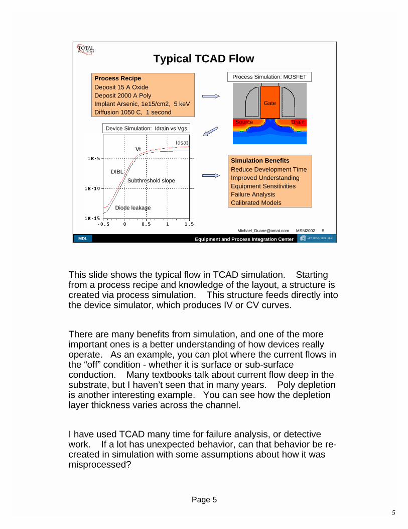
Typical TCAD FlowProcess RecipeDeposit 15 A OxideDeposit 2000 A PolyImplant Arsenic, 1e15/cm2, 5 keVDiffusion 1050 C, 1 second
Simulation BenefitsReduce Development TimeImproved UnderstandingEquipment SensitivitiesFailure AnalysisCalibrated Models
Device Simulation: Idrain vs Vgs
Subthreshold slope
IdsatVt
Diode leakage
DIBL
Gate
DrainSource
Process Simulation: MOSFET
This slide shows the typical flow in TCAD simulation. Startingfrom a process recipe and knowledge of the layout, a structure iscreated via process simulation. This structure feeds directly intothe device simulator, which produces IV or CV curves.
There are many benefits from simulation, and one of the moreimportant ones is a better understanding of how devices reallyoperate. As an example, you can plot where the current flows inthe “off” condition - whether it is surface or sub-surfaceconduction. Many textbooks talk about current flow deep in thesubstrate, but I haven’t seen that in many years. Poly depletionis another interesting example. You can see how the depletionlayer thickness varies across the channel.
I have used TCAD many time for failure analysis, or detectivework. If a lot has unexpected behavior, can that behavior be re-created in simulation with some assumptions about how it wasmisprocessed?
� Device simulation can also be performed without processsimulation.– doping profiles specified as Gaussian functions.– this approach is particularly relevant in the context of
compact model generation.
Although the previous slide showed process simulation as beingthe input to device simulation, most device simulators can createstructures on their own. The doping profiles might not be ascomplicated as what a process simulator would predict, but it isgood enough for many applications. And, this approach is veryfast compared to process simulation. I first saw it used by agroup simulating large power devices. At that time, the processsimulation for those structures was 20 hours. Also good forpeople who don’t trust process simulators.
� Inverse modeling of the Intel 1998 IEDM device viaoptimization of a parameterized device description.– Find structure to match electrical results
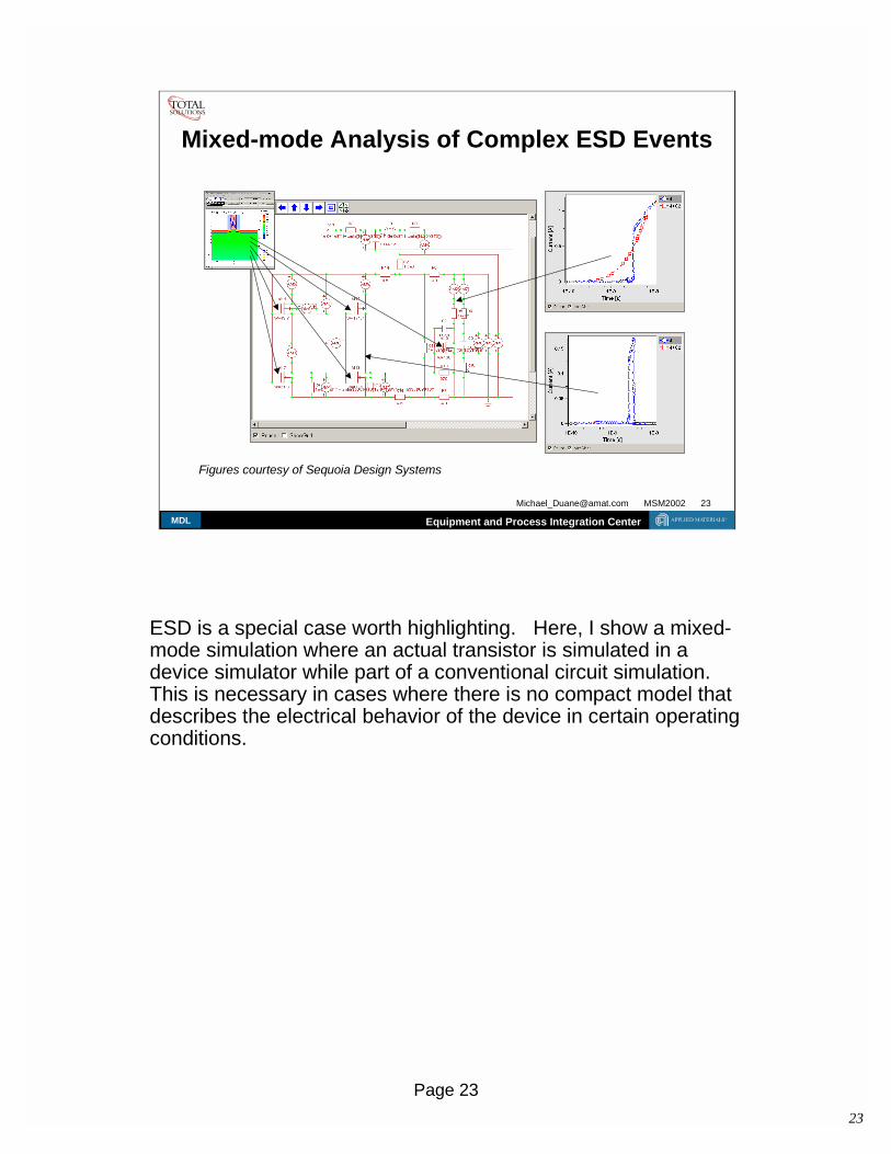
Figures courtesy of Sequoia Design Systems
Another TCAD application relevant to this discussion is theconcept of inverse modeling. Here we start with known devicecharacteristics, and then search for a structure that reproducesthese curves. This is a situation where you want to use devicesimulation only. People worry about uniqueness, but you canadd constraints to prevent unrealistic structures as solutions.
� Conceptually, TCAD results can be fed directly into ECAD.� In reality, the TCAD and ECAD communities are rather distinct.
– (although OPC and RC extraction has “successfully” movedto ECAD / EDA)
TCAD ECAD
The original title of this talk was “TCAD and ECAD - is there aconnection?”
It is not obvious why the connections are not better between theTCAD and ECAD worlds.
Next, we will explore some of the problems with TCAD, but theintent is to leave you with the impression that TCAD can be usedfor compact model generation.
Problems with TCAD� There are still many TCAD skeptics
– examples can always be found where the results don’tmatch measurements
� Common sources of these differences– insufficient physics (new materials)– inaccuracies in metrology (especially L and tox)– improper use of software tools (gridding, models)– missing process details (temperature ramps)– hidden assumptions in the software– lack of 3D effects (narrow width, line edge roughness)
� But properly used, simulation can be a powerful tool
There are many reasons why TCAD simulations don’t matchsilicon measurements, but this isn’t always because ofinadequacies in the model. Often, there are too many models toselect from, and the proper selection will give the desired results.
If technology would just stop evolving for a while, I am sure thatTCAD could become highly predictive. :)
But the lack of a 3D process simulator is a serious problem. 3Ddevice simulators have been around for many years.
And even though I have often spoken about the limitations ofTCAD, I have done so so that others can be aware of the pitfalls,and avoid them.
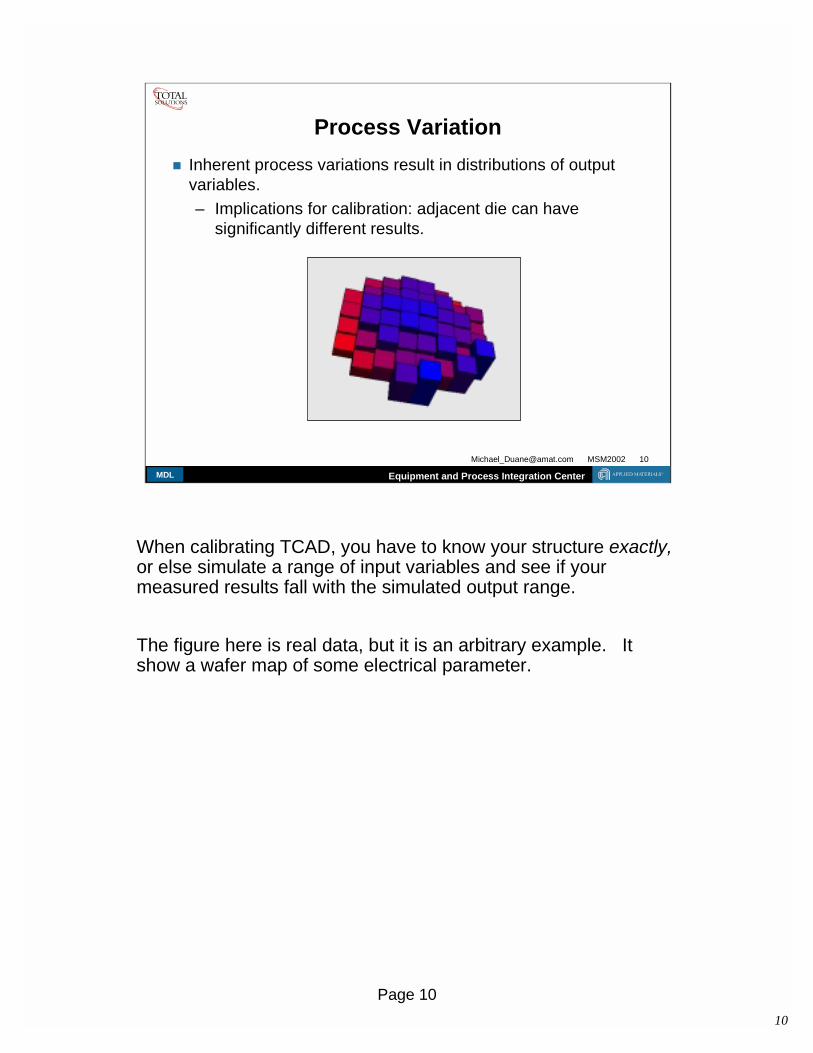
Process Variation� Inherent process variations result in distributions of output
variables.– Implications for calibration: adjacent die can have
significantly different results.
When calibrating TCAD, you have to know your structure exactly,or else simulate a range of input variables and see if yourmeasured results fall with the simulated output range.
The figure here is real data, but it is an arbitrary example. Itshow a wafer map of some electrical parameter.
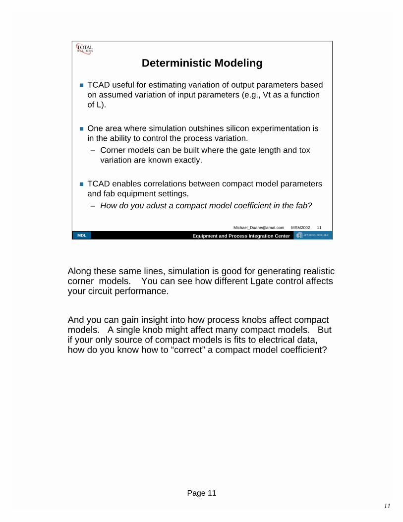
� TCAD useful for estimating variation of output parameters basedon assumed variation of input parameters (e.g., Vt as a functionof L).
� One area where simulation outshines silicon experimentation isin the ability to control the process variation.– Corner models can be built where the gate length and tox
variation are known exactly.
� TCAD enables correlations between compact model parametersand fab equipment settings.– How do you adust a compact model coefficient in the fab?
Along these same lines, simulation is good for generating realisticcorner models. You can see how different Lgate control affectsyour circuit performance.
And you can gain insight into how process knobs affect compactmodels. A single knob might affect many compact models. Butif your only source of compact models is fits to electrical data,how do you know how to “correct” a compact model coefficient?
� Applied has a major push in Process Module development, andTCAD is used to support this. Process Modules described inannual report:– http://www.appliedmaterials.com/financial/annual2001/AMAR01_FINAL.pdf
� Applied and ISE collaboration on process model calibration.– http://www.appliedmaterials.com/newsroom/pr-00261.html (Jan 2000)
Next, we will move on to a discussion of TCAD at AppliedMaterials. First, Applied is getting into the Process Modulebusiness, and TCAD is helpful for developing technology.
We also have a calibration project on-going with ISE (IntegratedSystems Engineering), a TCAD vendor, to improve their tools,and to provide calibrated TCAD to our equipment customers.
cleanroom, with capacityfor over 300 process andsupport tools.
� 248nm and 193nm lithocapability for 300mm.
� The equipment industry’smost advanced facility forprocess technologydevelopment.
We recently opened a new technology development center inSunnyvale.
Recall that we are an equipment maker, so these are state of theart tools, and beyond even. Applied does not make lithoequipment, so we rely on our litho partners. But again, state ofthe art tools.
ISE and Applied MaterialsGlobal Calibration Database
The figure above shows some of the areas where the calibrationproject with ISE initially focused on. There has also been workon oxidation modeling. Literally hundreds of SIMS have beentaken. This work is ongoing.
And these figures show how device simulators can reproducedeep submicron physics. A cynic might point out that I am justshowing how a compact model can fit a device simulation, butthere are equally good fits between silicon and TCAD not shownhere.
� TCAD is routinely used for pre-silicon, or Rev0, compact models.
� In a pre-silicon scenario, the final process flow is not known.This only adds to the modeling uncertainty.
� However, a key advantage of TCAD based compact models isself-consistency - coefficients will show the proper trends andcorrelations.– improbable combinations of coefficients eliminated.– TCAD better at trends than absolute values.– Better understanding of how equipment setting affect
compact model parameters.
Through personal knowledge, I know that Rev0 models are oftencreated from TCAD. I did this for a 1M DRAM. However, thereare few, if any, publications that demonstrate this.
I think an under-appreciated advantage of a simulation basedcompact model (as compared to an extrapolation of an existingmodel) is that the parameters will be more self-consistent.
� Other arguments in favor of a simulation based approach forcompact model generation:– early in the design process, accuracy is less important than
timeliness– the target Ion and Ioff are known, so that the TCAD results
can be adjusted to meet these.
� Although compact models are usually a fit of the silicon data, analternative approach is to use compact models as targets for theprocess to achieve !
TCAD for Compact Model Generation (3)� In a 1995 Compact Modeling Council meeting at SEMATECH,
an informal survey of the use of TCAD for compact modelgeneration showed:– Company A: hybrid approach for compact model generation
using TCAD and experimental extrapolation.– Company B: Produced 0.35um models completely from
TCAD based on a previously calibrated technology.– Company C: Has used TCAD in the past. But TCAD running
into limitations. Expensive to “close the loop”.– Company D: Every generation has a new processing step
and the modeling lags. So, TCAD doesn’t play a major rolein technology development.
(the first three companies had significant internal TCAD groups)
In 1995, a Compact Modeling Council survey showed that the useof TCAD in generating compact models ranged from complete tonone. The same results would probably be found today.
So the question for this audience of compact modelers is: howcan TCAD play a larger role? Email me the answer, or tell theITRS the next time around.
� Conceptually, TCAD could be used to develop new compactmodels, not just the coefficients.– The BSIM model family has not used TCAD at all for this
purpose.– A surprising gap in retrospect (from a TCAD perspective).
� But this is changing: “Generation of equivalent circuits fromphysics-based device simulation”– Pacelli, Mastrapasqua, and Luryi, IEEE Trans on CAD of IC’s, Nov 2000.
As far as I can tell, TCAD has historically not been used in thedevelopment of compact models. And considering how closeBerkeley and Stanford are, I find this somewhat ironic.
But this is changing, as demonstrated in other talks in thisworkshop.
� Looking forward:– how to couple advanced simulations (e.g. quantum scale) to
compact modeling research.– Compact models in the ballistic limit– RF devices - interconnect modeling as important as silicon
• transition frequencies, distortion, noise figures, etc.– New structures (double gate, FD SOI).– ESD modeling needs mixed-mode (device and circuit)
• compact models can’t handle breakdown
Here, I list some opportunities for collaboration between TCADand compact modeling. We need to discuss how to best createthe necessary interactions. But we are certainly approaching aregime where the device physics and even the device structurewill be changing significantly.
ESD is a special case worth highlighting. Here, I show a mixed-mode simulation where an actual transistor is simulated in adevice simulator while part of a conventional circuit simulation.This is necessary in cases where there is no compact model thatdescribes the electrical behavior of the device in certain operatingconditions.
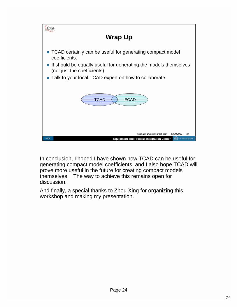
� TCAD certainly can be useful for generating compact modelcoefficients.
� It should be equally useful for generating the models themselves(not just the coefficients).
� Talk to your local TCAD expert on how to collaborate.
ECADTCAD
In conclusion, I hoped I have shown how TCAD can be useful forgenerating compact model coefficients, and I also hope TCAD willprove more useful in the future for creating compact modelsthemselves. The way to achieve this remains open fordiscussion.And finally, a special thanks to Zhou Xing for organizing thisworkshop and making my presentation.