The Space Congress® Proceedings 1973 (10th) Technology Today and Tomorrow Apr 1st, 8:00 AM The Space Shuttle Main Engine And Its Maintenance Features The Space Shuttle Main Engine And Its Maintenance Features V. J. Wheelock Manager, SSME Logistics, Rocketdyne Division/Rockwell International, Canoga Park, California Follow this and additional works at: https://commons.erau.edu/space-congress-proceedings Scholarly Commons Citation Scholarly Commons Citation Wheelock, V. J., "The Space Shuttle Main Engine And Its Maintenance Features" (1973). The Space Congress® Proceedings. 3. https://commons.erau.edu/space-congress-proceedings/proceedings-1973-10th/session-5/3 This Event is brought to you for free and open access by the Conferences at Scholarly Commons. It has been accepted for inclusion in The Space Congress® Proceedings by an authorized administrator of Scholarly Commons. For more information, please contact [email protected].
Transcript
The Space Congress® Proceedings 1973 (10th) Technology Today and Tomorrow
Apr 1st, 8:00 AM
The Space Shuttle Main Engine And Its Maintenance Features The Space Shuttle Main Engine And Its Maintenance Features
V. J. Wheelock Manager, SSME Logistics, Rocketdyne Division/Rockwell International, Canoga Park, California
Follow this and additional works at: https://commons.erau.edu/space-congress-proceedings
Scholarly Commons Citation Scholarly Commons Citation Wheelock, V. J., "The Space Shuttle Main Engine And Its Maintenance Features" (1973). The Space Congress® Proceedings. 3. https://commons.erau.edu/space-congress-proceedings/proceedings-1973-10th/session-5/3
This Event is brought to you for free and open access by the Conferences at Scholarly Commons. It has been accepted for inclusion in The Space Congress® Proceedings by an authorized administrator of Scholarly Commons. For more information, please contact [email protected].
THE SPACE SHUTTLE MAIN ENGINE AND ITS MAINTENANCE FEATURES
V.-J. WheelockManager, SSME Logistics
Rocketdyne Division/Rockwell InternationalCanoga Park, California
ABSTRACT
The Space Shuttle Main Engine* (SSME) is a reusable, high-performance rocket engine being developed to satisfy the performance, life, reliability, and operational requirements of the Space Shuttle Qrbi- ter. The design includes simple, low-cost mainte nance features resulting from a viable maintaina bility program dedicated to minimizing engine cost per flight.
DESCRIPTION
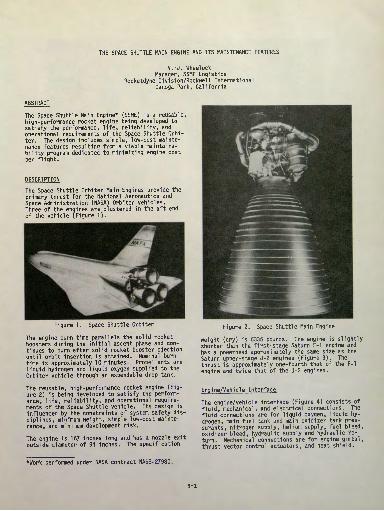
The Space Shuttle Orbiter Main Engines provide the primary thrust for the National Aeronautics and Space Administration (NASA) Orbiter vehicles. Three of the engines are clustered in the aft end of the vehicle (Figure 1),
Figure 1. Space Shuttle Orbiter
The engine burn time parallels the solid rocket boosters during the initial ascent phase and con tinues to burn after solid rocket booster ejection until orbit insertion is attained. Nominal burn time is approximately 10 minutes. Propel 1 ants are liquid hydrogen and liquid oxygen supplied to the Orbiter vehicle through an expendable drop tank.
The reusable, high-performance rocket engine (Fig ure 2) is being developed to satisfy the perform ance, life, reliability, and operational require ments of the Space Shuttle vehicle. Its design is influenced by the constraints of system safety dis ciplines, minimum weight, simple low-cost mainte nance, and minimum development risk.
The engine is 167 inches long and has a nozzle exit outside diameter of 94 inches. The specification
Figure 2. Space Shuttle Main Engine
weight (dry) is 6335 pounds. The engine is slightly shorter than the first-stage Saturn F-l engine and has a powerhead approximately the same size as the Saturn upper-stage J-2 engines (Figure 3). The thrust is approximately one-fourth that of the F-l engine and twice that of the J-2 engines.
Engine/Vehicle Interface
The engine/vehicle interface (Figure 4) consists of fluid, mechanical, and electrical connections. The fluid connections are for liquid oxygen, liquid hy drogen, main fuel tank and main oxidizer tank pres- surants, nitrogen supply, helium supply, fuel bleed, oxidizer bleed, hydraulic supply and hydraulic re turn. Mechanical connections are for engine gimbal, thrust vector control actuators, and heat shield.
*Work performed under NASA contract NAS8-27980.
5-1
Figure 3. Engine Size Comparison
OXYGEN• LOW PRESSURE
OXIDIZER TURBOPUMP
MECHANICAL• GIMBAL ATTACH POINT• THRUST VECTOR
CONTROL ACTUATOR ATTACH POINTS
• HEAT SHIELD (360° CONTACT ON THRUST CHAMBER NOZZLE - NOT SHOWN)
ELECTRICAL• AC/DC POWER• VEHICLE COMMANDS• DATA TRANSMISSION
HYDROGEN• LOW PRESSURE
FUEL TURBOPUMP
PRESSURANTS/PNEUMATICS/ BLEEDS/HYDRAULICS• FUEL AND OXYGEN MAIN TANK PRESSURANTS
• NITROGEN AND HELIUM SUPPLY
• FUEL AND OXIDIZER BLEEDS• HYDRAULIC SUPPLY AND
RETURN
Table V. SSME Operating Requirements
Figure 4. Engine/Vehicle InterfaceElectrical connections are for the a-c and d-c power supply, operational and checkout commands to the engine, and data transmission. Two low-pres sure turbopumps are fixed to the vehicle propel!ant ducting. Engine interconnecting ducting to the turbopumps contain internally or externally tied bellows systems to allow flexing. The flexing per mits the rest of the engine to gimbal ±11 degrees in pitch and ±9 degrees in yaw for thrust vector control by vehicle-supplied actuators.
Engine Operating Requirements
Engine operating requirements are shown in Table 1. The engine responds to vehicle commands for start and shutdown and variations in thrust and mixture ratio. The operating range of thrust varies from 50 to 109 percent; this includes minimum power level (MPL), normal power level (NPL), and emer gency power level (EPL). The maximum level (i.e., EPL) is available for emergencies (e.g., one engine
Thrust (NPL), pounds• Sea Level• Vacuum
MPL, percent EPL, percent Chamber Pressure, psia Area Ratio Specific Impulse (nominal), seconds
t Sea Level• Vacuum
Mixture Ratio Length, inches Diameter, inches
t Powerhead• Nozzle Exit
Life
Weight (dry), pounds
375K470K50109297077.5
363.2455.26.0167
105 x 95.4947.5 hoursTOO starts:
6 EPL's 94 NPL's 6335
out operations). The engine is started on the launch pad, necessitating a nozzle expansion ratio (e) that will flow full at sea level and also pro vide high performance under vacuum conditions. The nominal burn time is 10 minutes (600 seconds) with a total operational service life of 7.5 hours or 100 starts.
Engine System
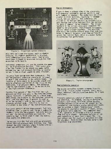
The engine has a staged combustion power cycle (Figure 5) in which the gases from the individual turbopumps are redirected to the main injector for additional combustion to extract more energy.
5-2
Figure 5* Propel! ant System SchematicWith this cycle and the highest optimum chamber pressure, the highest performance is obtained, since combustion takes place under ideal mixing conditions followed by expansion through the high expansion ratio nozzle.
Individual preburners are used to provide the power for the high-pressure turbines. This system pro vides the flexibility to adjust the power split between the two high-pressure turbines by control valves in the oxidizer supply to each preburner.
The propel 1 ant system uses four turbopumps. The two low-pressure turbopumps operate at low speed to permit low pressures in the vehicle tanks. The function of these pumps is to provide enough pres sure to eliminate cavitation at the inlets of the high-speed, high-pressure pumps. The discharge from the low-pressure pumps is fed to the inlets of the high-pressure turbopumps.
Seventy-five percent of the flow from the high- pressure oxidizer pump goes to the main combustion chamber injector, 10 percent goes to a boost pump that raises the pressure to the preburner operating level, and the remaining 15 percent is used to drive the hydraulic turbine that powers the low- pressure oxidizer pump. This flow is then re- circulated to the inlet of the high-pressure pump.
Twenty-one percent of the high-pressure fuel pump discharge flow is used to cool the main combustion chamber, drive the low-pressure fuel -pump turbine, and cool the hot-gas manifold and injector. The remaining fuel is first used to cool the nozzle, then supply the preburners.
The hot-gas from the fuel and oxidizer preburners drives the high-pressure pump turbines, then flows through the main injector, where it burns with oxi dizer and additional coolant fuel.
Engine Arrangement
Figure 6 shows a cutaway view of the preburners, high-pressure turbopumps, hot-gas manifold, and main combustion chamber. The preburners are close coupled to their turbines, resulting in minimum- length, hot-gas ducting. The turbopumps are mounted to the hot-gas manifold to provide a com pact package and canted outboard from the vertical for ease of removal for maintenance. The hot-gas manifold is the primary structural component for mounting the preburners, high-pressure turbopumps, and the thrust chamber assembly. This manifold also ducts the turbine exhaust gases from both tur bines to the main injector, providing uniform flow across the injector face, which is a major factor in achieving high performance.
PREBURNER PREBURNER
'Atbttt TURBOPUMP
HYDROGEN TURBOPUMP
MAIM COMBUSTION CHAMBER
Figure 6. Engine Arrangement
Engine/Vehicle Operation
The engine controller accepts commands from the vehicle to initiate engine prestart, start, main- stage, shutdown, and post-shutdown modes for flight operations.
Prestart operations consist of checkout, purging, and chill down. On command, the engine performs an automatic self-check, initiates system purging, actuates engine-mounted valves for propel!ant re- circulation, and monitors engine operational readi ness to provide a single "engine-ready" signal. The engine is started on receipt of start, thrust, and mixture ratio commands. The commanded level to NPL operation is achieved within 3.5 seconds from the start signal. Mainstage includes all en gine operations at power levels above MPL. The same valves used for start and mainstage are used for shutdown. Post-shutdown includes purging and propel!ant dump operations.
5-3
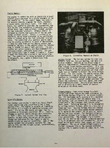
Engine Control
The engine is controlled with an electronic digital control system packaged in a single assembly called the controller. In the control mode, the control ler accepts vehicle commands for start, shutdown, mixture ratio, and thrust level. From these com mands, the controller provides the appropriate sig nals to the five hydraulically actuated propellant valves (main fuel, main oxidizer, chamber coolant, and two preburner oxidizer). Primary control is achieved by closed-loop operation of the two pre burner oxidizer valves. Thrust is controlled by adjusting the oxidizer preburner valve and mixture ratio is controlled by the fuel preburner oxidizer valve. The controller also monitors engine opera tion to provide protection in event of malfunction. It receives data from various engine sensors and transmits the data to the vehicle where the informa tion is stored for post-flight analysis. The con troller and sensor systems are dual -redundant for a fail-operational , fail-safe capability. The con trol system data flow is shown in Figure 7. Figure 8 shows the controller mounted to the thrust cham ber. The controller is being designed and produced by Honeywell , Inc., under a subcontract from Rocketdyne.
VEHICLE
COMMAND
Figure 7. Control System Data Flow
Long-life Design
The Orbiter main engine is the first large liquid rocket engine designed specifically for a long service life. The engine is capable of completing 100 starts or 7.5 hours of operation between over hauls. Six of the 100 starts are specified for operation at 9-percent overthrust (EPL). Specific changes to earlier engine designs were necessary to fulfill this long service life requirement. However, in each case, the weight of the design change was evaluated for its impact on engine weight-to-orbiter payload capability. Some of the engine systems and components designed for long service life are the hot-gas system, turbomachinery, and valve seats.
Figure 8. Controller Mounted on Engine
Hot-Gas System - The hot-gas system includes pre- burners, turbines, hot-gas ducting, and main com bustion chamber. Because of the broad range of operating temperatures, differential thermal expan sion imposes severe design constraints. If a long service life is to be obtained, stresses resulting from differential thermal expansion and from other loads must be limited to prevent low cycle fatigue of parts. For this reason, the engine design .uses a regeneratively cooled hot-gas system. Gaseous hydrogen is circulated through a double-wall sys tem for cooling. The coolant system provides flow around the preburners, turbines, ducts, and other high-temperature areas. Turbine blade roots are cooled directly by a small amount of coolant directed at the blade roots.
Turbomachinery - Cumulative damage from both fatigue and creep rupture has been considered in the turbine designs (Figure 9) to ensure durabil ity. All turbopump seals operate with a positive clearance to prevent wear and ensure long life. Low bearing loads are ensured by a balance piston system within the turbopump that reduces axial shaft loads. Turbopump bearing life is determined by rolling-contact fatigue, which is a function of speed and load. Bearing fatigue data are treated statistically, so the recommended design approach is to maximize the probability of survival within the desired duty period. The standard criterion of bearing fatigue life is B-JQ or 90-percent sur vival probability. The fatigue life criterion used for the Orbiter main engine turbopump bearings is Bi or 99-percent survival probability. This is based on the most severe load, speed, and life re quirements. The use of vacuum melted materials further increases life so the average predicted bearing life is approximately 65 times the B, life value.
5-4
PUMP DISCHARGE
BALANCE PISTON
TURBINE INLET
BEARINGS
BEARINGS
3-STAGE PUMP
Figure 9. High-Pressure Fuel Turbopump
Propel 1 ant Valves - A retractable seal for the pro- pellant ball valves (Figure 10) is a feature unique to the engine, added specifically to provide long life and reusability. The valves are required to modulate during operation (to provide performance control) and to provide positive shutoff during start and stop operations. They must function with high reliability in the severe operating environ ment of cryogenic temperature, high vibration, and high stress. The long service life of the valve is ensured by eliminating rubbing between the ball and ball seal by lifting the ball seal before the ball moves. This feature allows the ball seal to be made from a plastic material having sealing properties required for zero liquid leakage.
:;A)DETAIL
Check and Anti flood Valves - Check valve seat life has been a concern on previous engines be cause of poppet chatter. As poppet opening or seating occurs, small pressure variances occur be cause of changes in flow. These conditions set up alternating controlling forces on the closing spring or the pressure/area force. SSME check valves and the antiflood valve (Figure 11) have an augmented seat area feature to open or seat the poppet positively without oscillation. In the anti- flood valve, as the pressure buildup acts on the opening area, spring forces are overcome and the poppet retainer retracts. However, the poppet re mains seated through a smaller compressed spring acting between the poppet and poppet retainer. As
Figure 11. Antiflood Valve
poppet retainer travel takes place, mechanical restraining contact is made with the poppet and it is unseated. As the poppet opens, the poppet seat area is exposed to downstream pressure and the pop pet unseating force increases. The reverse action takes place on closing. In the purge check valves,
Figure 10. Main Oxidizer Valve (Typical Ball Valve)
-:5-5
after the poppet initially opens, pressure down stream of the poppet seat acts on a larger area to increase the unseating force.
MAINTENANCE FEATURES
An engine maintenance concept that was automated and simple, yet provided confidence that the engine was ready to fire again, was developed to meet the turnaround time constraints of the Orbiter vehicle.
Automatic checkout, operational monitoring of flange leakages, and automatic propel!ant valve seat leakage detection have replaced the manual leak and functional techniques used on previous en gine systems. Life monitoring techniques of in ternal inspection, maintenance instrumentation, and drain system leak checks resulted from a maintain ability analysis conducted early in the design phase. Since corrective maintenance represents the largest single expenditure of resources during the SSME turnaround cycle, hardware accessibility and handling were emphasized early in the design phase. This maintenance concept results in a maintenance cycle for the three Orbiter main engines requiring an average of 25 hours of the 160-hour Orbiter turnaround.
Automatic Checkout
Programs for hardware checkout are loaded into the engine controller from the launch processing sys tem (IPS). The engine controller programs the checkout, analyzes the data, and reports to the IPS via the vehicle engine electrical interface (VEEI) and the vehicle. Redundant components are checked individually.
Components checked automatically include the con troller, all sensors, propel!ant valve actuators, bleed valves, solenoids, pressure-actuated valves, spark igniters, burst diaphragms, and check valves.
Flange Leakage Monitoring
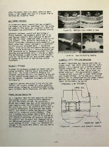
It is important that the leak detection and isola tion system, function during hot-fire operation (flight) and retain the data for ground use. Flight environment leaks may not be reproduced when leak checking under the less-severe ground check out conditions, since the operating environment of cryogenic temperature, high-pressure and stress levels, and vibration cannot be adequately simu lated during turnaround ground checkout. Chem ically treated color-change tape (Figure 12) or a leak-indicating coating (Figure 13) is applied to each separable connection and external leak point. The external leak detectors are inspected during the 100-percent external visual inspection of each engine between flights. Comparison standards de veloped in the engine test program are used during the inspection.
Figure 12. Hydrogen Leak-Detecting Tape
PRESSURE TRANSDUCER AFTER APPLICATION OF LEAK DETECTION COATING
Figure 13. Leak-Indicating Coating
Propel1 ant Valve Seat Leak Detection
Automatic downstream seat leakage detection re places manual leak checks used on earlier rocket engines. This checkout uses ultrasonic sensors located (Figure 14) in four of the valves (main fuel, main oxidizer, and fuel and oxidizer pre- burner oxidizer). The characteristic sound of leakage at each valve will be established during development testing. During checkouts, vehicle systems will be pressurized and the sensor signals measured and compared with acceptable levels stored in the controller memory.
ULTRASONIC LEAK DETECTOR-
INLET
PROPELLANT DUCT-
Figure 14. Ultrasonic Leak Detector Location
5-6
Life Monitoring
Engine life is monitored by internal inspection, maintenance instrumentation, and drain system leak checks.
Internal Inspection - Commercial airlines agreespei althat internal inspection of propulsion systems is
cost effective. Studies with TWA show the airlines and the Space Shuttle Program have similar require ments. For this reason, a major effort was ex pended to provide full internal inspection capabil ity. This effort defined requirements, selected equipment, scheduled usage, and designed access ports.
Figure 15 shows locations that have been desig nated as internal inspection points in the low- pressure and high-pressure turbopumps, oxidizer dome, flowmeters, thrust chamber injector, and preburners.
Figure 15. Internal Inspection Locations
Scheduled inspection requirements were studied and each normal engine access point and instrumenta tion port has been located to facilitate these in spections. In addition, all other engine access points and instrumentation ports were studied dur ing the preliminary design period and located to provide access to potential inspection points.
The internal inspection equipment (Figure 16) con sists of flexible and rigid optic borescope de vices, photographic attachments (color and black and white), and closed-circuit television with videotape recording capability.
A special guide tube (Figure 17) has been devised to reduce the time required to orient and hold in spection devices once they have been inserted. These guide tubes are supplied as GSE with the engine.
Figure 16. Internal Inspection Equipment
Figure 17. Borescope Guides
Figure 18 shows a typical internal inspection with the inspection equipment inserted in the preburners.
Special Data Analysis - Trend analyses of mainte nance data are conducted periodically with the data obtained from internal inspection. Figure 19 shows the maintenance data recording sensors (used also for turnaround corrective maintenance determina tions) that provide the data for the trend analysis.
Drain Systems Leak Checks - An analysis of in ternal drain systems resulted in noncritical sys tems drains to be ducted overboard. These systems are periodically leak checked to determine trends and assist in establishing overhaul tasks.
Fastener Load Verification - In the event loss of fastener load is suspected during engine mainte nance, it can be verified by the ultrasonic exten- someter (Figure 20) without backing off and re- torquing the fastener. On this engine, designers will specify axial preload in lieu of torque val ues for critical fasteners. These preloads will be measured by an extensometer that measures bolt length change (bolt load) by ultrasonic wave travel time. It is easy to use by attaching a small sensor to the bolt head. Readout is visual.
5-7
INSPECTIONCAMERA
Figure 18. Prebumer Internal Inspection
Figure 19. Maintenance Data Recording Sensors
Figure 20. Fastener Load Verification Equipment
Fastener unloaded length information will be per manently retained and the information will allow load verification in the installed condition by setting the unloaded reference data for the fastener into the reader.
IRiJ Accessibility
Corrective maintenance represents the largest single expenditure of time and resources during the SSME turnaround cycle. It consists of on-the-vehicle repair of engines, and in a limited number of cases, engine removal. On-the-vehicle maintenance of the SSME gives lowest maintenance cost and highest reliability. Although an engine can be changed faster than some of the larger components, the en gine change usually involves violating many more systems to make the repair and removes a complete system that has been functioning satisfactorily. This increases cost. To reduce cost and retain integrity, line replaceable unit (LRU) replacement is preferable and LRU's of the SSME were selected on this basis.
LRU's have GSE attach lugs and handling adapters, when required by their weight or size, and when required for easy maneuvering. Figure 21 shows a typical engine component being removed with an overhead hoist. (A component manipulator is used if engine clocking causes hardware interference.)
Figure 22 shows a propel!ant duct being removed with bellows support (strong back). Compared to earlier rocket engines, SSME propel1 ant ducts carry very high pressure. Although designed for minimum weight, the ducts are rugged and therefore diffi cult to separate from mating hardware. To help separate the mating surfaces for corrective mainte nance, duct flange spreaders (Figure 23) will be developed and attach points included in the engine design.
Production engines are acceptance tested at NASA's Mississippi Test Facility and delivered to Kennedy Space Center for installation in the vehicles. Following a program of integrated system tests, flight readiness tests, and verifical flight tests, the vehicles become operational. A typical opera tional maintenance cycle is shown in Figure 24 and described below.
SAFING
TURNAROUND MAINTENANCE
PRELAUNCH
INSPECTION AND DRYING
DATA ANALYSIS
1 AUT 1 CUE
OMATIC CKOUT
EXTERNAL INSPECTIONS
1 ILIFE INSPECTIONS (PERIODIC)
; 4 •MAINTENANCE PLANNING
V V
CORRECT IVE MAINTENANCE \-* AND FLIGHT
INSPECTIONS AND LAUNCH PREPARATIONS
Figure 24. Maintenance Cycle
down from re-entry, the engine is dried and an ex ternal visual inspection conducted. The visual in spection ensures there are no gross leakages or damage that would endanger personnel in the turn around maintenance area. Flight data plus the re sults of the safing inspection are sent to the vehicle Maintenance Planning function and corrective maintenance planning is initiated.
Turnaround Maintenance - During the routine mainte nance period, an automatic checkout and a 100- percent external visual inspection are conducted. In addition, each engine periodically receives a life inspection. These inspections are alternately scheduled for optimum man loading. The results of routine maintenance are sent to the Maintenance Planning function where it is combined with the re sults of the safing inspection and flight data analysis to determine the corrective maintenance actions. Corrective maintenance is conducted on the vehicle or, in a limited number of cases, the engine is removed for maintenance or replacement.
Checkouts and leak checks are performed at the con clusion of turnaround maintenance to verify the corrective maintenance actions. A flight readiness test, performed before mating the Orbiter with the solid rocket motors and external tank, confirms all maintenance actions taken during turnaround and certifies the engines ready for the next flight.
Figure 23. Duct Flange Spreaders
5-9
Prelaunch Inspection and Preparations - Protective covers and closures are removed at the launch pad and the engines are visually inspected to ensure the engines are ready for launch. Controller memory verifications are conducted and the engines are ready for the launch activities.
SUMMARY-
The advent of the Space Shuttle introduced many new challenges to the rocket engine designer. A high- performance, lightweight, long-life propulsion
system was needed. Moreover, a propulsion system was needed that could be maintained in an airline- type maintenance environment (i.e., low cost, fast turnaround). The SSME has successfully answered these challenges. Tried and proved technologies were used to ensure that performance, weight, and life requirements are satisfied. However, innova tions in turnaround maintenance, heretofore unnec essary to space engine maintenance programs, will be used to ensure fast, reliable turnaround mainte nance. Designs for automatic checkout, leak detec tion, and hardware accessibility will be verified during a Maintainability Demonstration Program.