Turk J Elec Eng & Comp Sci, Vol.18, No.6, 2010, c T ¨ UB ˙ ITAK doi:10.3906/elk-0905-40 The use of FPGA in field-oriented control of an induction machine ¨ Ozkan AKIN, ˙ Irfan ALAN Department of Electrical and Electronics Engineering, Faculty of Engineering Ege University, Bornova, 35100, ˙ Izmir-TURKEY e-mail: [email protected], [email protected]Abstract In this study, the feasibility of embedding the field oriented control (FOC) of an induction machine into field programmable gate arrays (FPGA) is investigated. An indirect FOC of an induction machine is simulated in a Matlab Simulink environment using a Xilinx System Generator implemented in a Xilinx Spartan-3 XC3S200 FPGA board. Design of the developed controller for the induction machine is simulated via a Simulink full digital platform. The resulting design has a flexible and modular structure where the designercan customize the hardware blocks by changing the number of inputs, outputs, and algorithm when it is compared to the designs implemented using classical microcontrollers and digital signal processors. With its flexibility, other control algorithms can easily be programmed and embedded into the FPGA. The controller developed can be imbedded and implemented on the Digilab S3 Spartan-3 XC3S200 FPGA development board produced by the Digilent Company. Performance of the developed system has been tested at different load torques and various inductionmachine speeds. Key Words: Field Orientation Control, Induction Machine, Field Programmable Gate Arrays (FPGA), Matlab Simulink, Xilinx System Generator, VHDL 1. Introduction The field of controlled electrical drives has seen rapid expansion in recent years, due mainly to achievements obtained in semiconductors for both power and signal electronics. The technological improvements have opened the way for really effective drive designs. The electrical machine drive controls have become more accurate and robust than ever. Vector controlled AC drives have taken their share from these achievements. As is known, a vector controlled AC machine acquires almost every advantage of converter controlled DC machine while getting rid of the mechanical commutation problems. On the other hand, this control structure yields a high dynamic performance by achieving a better steady state and transient control [1]. Nowadays, Field Programmable Gate Arrays (FPGAs) have been widely used as key components in implementing high performance processors. The speed, size and the number of inputs and outputs of a 943
In this study, the feasibility of embedding the field oriented control (FOC) of an induction machine
into field programmable gate arrays (FPGA) is investigated. An indirect FOC of an induction machine
is simulated in a Matlab Simulink environment using a Xilinx System Generator implemented in a Xilinx
Spartan-3 XC3S200 FPGA board. Design of the developed controller for the induction machine is simulated
via a Simulink full digital platform. The resulting design has a flexible and modular structure where the
designer can customize the hardware blocks by changing the number of inputs, outputs, and algorithm when
it is compared to the designs implemented using classical microcontrollers and digital signal processors. With
its flexibility, other control algorithms can easily be programmed and embedded into the FPGA.
The controller developed can be imbedded and implemented on the Digilab S3 Spartan-3 XC3S200 FPGA
development board produced by the Digilent Company. Performance of the developed system has been tested
at different load torques and various induction machine speeds.
Key Words: Field Orientation Control, Induction Machine, Field Programmable Gate Arrays (FPGA),
Matlab Simulink, Xilinx System Generator, VHDL
1. Introduction
The field of controlled electrical drives has seen rapid expansion in recent years, due mainly to achievementsobtained in semiconductors for both power and signal electronics. The technological improvements have openedthe way for really effective drive designs. The electrical machine drive controls have become more accurate androbust than ever. Vector controlled AC drives have taken their share from these achievements. As is known, avector controlled AC machine acquires almost every advantage of converter controlled DC machine while gettingrid of the mechanical commutation problems. On the other hand, this control structure yields a high dynamicperformance by achieving a better steady state and transient control [1].
Nowadays, Field Programmable Gate Arrays (FPGAs) have been widely used as key components inimplementing high performance processors. The speed, size and the number of inputs and outputs of a
943
Turk J Elec Eng & Comp Sci, Vol.18, No.6, 2010
modern FPGA far exceeds that of a microprocessor or DSP processor. FPGA is ideally suited for makinghigh-performance processors with a capability for implementing highly parallel arithmetic architectures [2].
Field Orientation Control (FOC) was initially proposed at the beginning of the 1970s by F. Blashke [3]
and, similarly, Direct Torque Control (DTC) was initially proposed in mid 1980s by Depenbrock [4, 5]. Takahashi
and Noguchi [6, 7] worked on vector control methods of ac machines. Although FOC ac machines exhibit DCservo performance, this type of control method is disadvantaged due to the dependence of the method on motorparameter variations. In recent years, many studies have been conducted to accurately determine these motorparameters and subsequently integrate them into the control structure. On the other hand, the DTC methodis simple, independent of parameter variation and does not require a current controller. However, the DTCmethod does not have good performance at low speeds due to its dependence on induced speed voltage. Studiesemploying the DTC have tried to overcome this disadvantage, but since the solutions are both complex andintroduce parameter dependence, the attractiveness of this method is diminished.
Thought Digital Signal Processor (DSP) technologies are available for digital ac motor control applications
[8], with achievements in Application Specific Integrated Circuits (ASICs) and Field Programmable Gate Arrays
(FPGAs), the usage of ASICs and FPGAs in motor control and drive applications are, too, becoming widespread
[9]. Introduced in 1984, FPGAs initially provided only peripheral interface to main processors. They now arestarting to be used in tasks varying from the main controller in motor control applications, to control the wholesystem [10].
The first applications of FPGAs in motor control started with Herbert and Beierke [11] and continued
with Cirstea, Imecs, Monmasson, Poure and their research groups [12, 13, 14, 15].
Induction machine vector control studies using ASIC-FPGAs employing VHDL and Verilog HardwareDescription Languages have been reported in literature [3, 9, 16, 17, 18, 19, 20,]. In some part of these studies,
DTC [16, 17, 18, 20] and FOC [3, 9] drives are designed by using VHDL language; and in others FOC drives
are designed by using Verilog language [19]. This design by International Rectifier (IR) engineers is a flexible
ASIC design developed as a unique servo-on-a-chip Application Specific Standard Product (ASSP) which can
compete with classical motion DSPs for cost sensitive applications [19].
Classical processor standard design flow is followed in FPGA designs using VHDL/Verilog hardwaredescription languages. This classical design flow causes a great deal of time consumption in the controllerdesign of complex systems, as in the case of high performance ac servo drives. The reduction in the design time,the increase in the design reusability, reliability and accuracy would reduce the time to market and the cost ofthe production. For this reason and they provide virtual prototype production; Xilinx System Generator (XSG)
[7, 21, 22, 23, 24, 25] and VHDL-AMS [26] usage have become widespread.
Very complex designs can be made easily with graphical algorithm approach, even by users foreignto the VHDL/Verilog programming languages, by using the Xilinx System Generator in Matlab/Simulinkenvironment. Vector control algorithm designs completed with this method allows one to observe easilythe effects of hysteresis band, different PI controller coefficients in speed regulator, bit capacity and differentsampling times of Analog/DigitalConverter (ADC), the width of the fixed point system used in the design on fluxand torque performance of the machine in simulation environment before the system is tested experimentally.An optimized controller can be designed with appropriate changes. VHDL/Verilog codes can be obtainedautomatically from Xilinx System Generator after completing the design in software environment, and then can
944
AKIN, ALAN: The use of FPGA in field-oriented control of an induction machine,
be downloaded to the FPGA chip to complete the design in hardware. Thus, since the errors that might occurduring the experimental tests is reduced to a minimum even before the tests during the software design stage,the experimental costs would be reduced as well.
DTC controller [7, 23] and vector controller applications with rotor flux estimation [22] have been reportedin the literature. A motor control library has been formed for vector control applications by using Xilinx SystemGenerator in Matlab/Simulink environment and this library is used in the field-oriented control of induction
machine fed from a hybrid converter [10, 21].
Here in this study, an indirect field oriented controller is modeled by a Xilinx System Generator inMatlab/Simulink environment and induction machine is driven by the related controller in software environmentwith appropriate simulations, and the results are analyzed. The VHDL codes generated automatically fromXilinx System Generator are embedded in a Spartan 3 FPGA kit [27].
2. Background
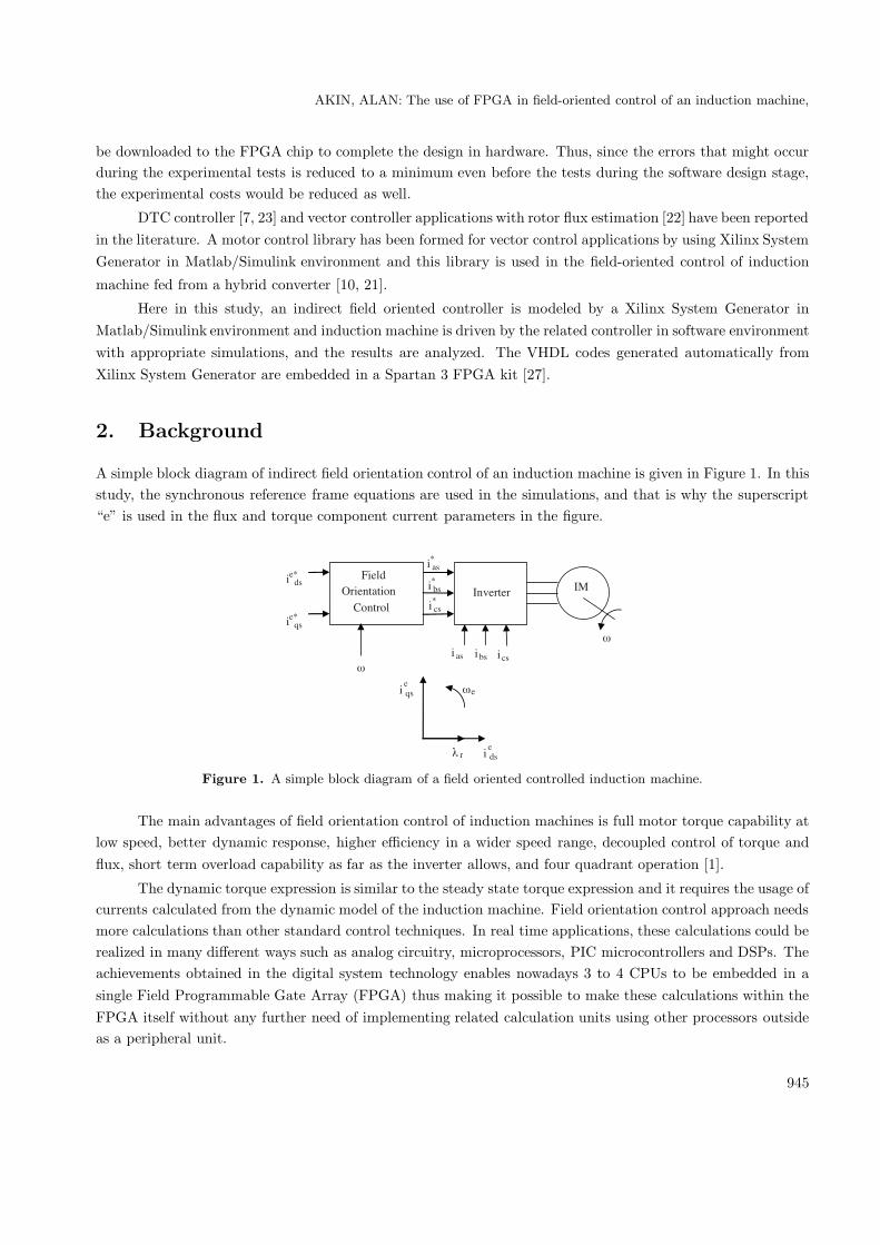
A simple block diagram of indirect field orientation control of an induction machine is given in Figure 1. In thisstudy, the synchronous reference frame equations are used in the simulations, and that is why the superscript“e” is used in the flux and torque component current parameters in the figure.
������������ ����
������ ��
����
����
�����
�����
�
�
����
����
����
� �� � �� � ��
Figure 1. A simple block diagram of a field oriented controlled induction machine.
The main advantages of field orientation control of induction machines is full motor torque capability atlow speed, better dynamic response, higher efficiency in a wider speed range, decoupled control of torque andflux, short term overload capability as far as the inverter allows, and four quadrant operation [1].
The dynamic torque expression is similar to the steady state torque expression and it requires the usage ofcurrents calculated from the dynamic model of the induction machine. Field orientation control approach needsmore calculations than other standard control techniques. In real time applications, these calculations could berealized in many different ways such as analog circuitry, microprocessors, PIC microcontrollers and DSPs. Theachievements obtained in the digital system technology enables nowadays 3 to 4 CPUs to be embedded in asingle Field Programmable Gate Array (FPGA) thus making it possible to make these calculations within theFPGA itself without any further need of implementing related calculation units using other processors outsideas a peripheral unit.
945
Turk J Elec Eng & Comp Sci, Vol.18, No.6, 2010
2.1. Synchronous reference frame dynamic model of induction machine
The synchronous reference frame equations in d- and q-axis model of the induction machine are:
veqs = rsi
eqs + pλe
qs + weλeds (1)
veds = rsi
eds + pλe
ds − weλeqs (2)
veqr = 0 = rri
eqr + pλe
qr + (we − wr) λedr (3)
vedr = 0 = rri
edr + pλe
dr − (we − wr)λeqr (4)
λeqs = Lsi
eqs + Lmieqr (5)
λeds = Lsi
eds + Lmiedr (6)
λeqr = Lmieqs + Lri
eqr (7)
λedr = Lmieds + Lri
edr . (8)
Here, p denotes the differential operator d/dt. The torque expression in de , qe variables is given as
T =32
P
2Lm
Lr
(λe
drieqs − λe
qrieds
). (9)
If it is rewritten in complex vector notation it can be given in the form
T =32
P
2Lm
LrIm
(λe
qdr × ie∗qds
)(10)
where Im denotes the imaginary part of the complex product, and where
λeqdr = λe
qr − jλedr (11)
ieqds = ieqs − jieds (12)
ie∗qds = ie∗qs − jie∗ds. (13)
It was shown that the desired torque control could be achieved if the current component that produced therotor flux and the current component that produced torque could be decoupled. To further illustrate this, therotor flux λe
qdr is allowed to be aligned with the d-axis so that
λedr = λe
qdr = λeqr − jλe
dr (14)
andλe
qr = 0. (15)
If the constraints given in equations (14) and (15) are maintained, equations (5)–(8) can be represented by the
vector diagram in Figure 2 [28].
946
AKIN, ALAN: The use of FPGA in field-oriented control of an induction machine,
edr
qre
dse
i qs
qdse
q-axis
d-axis
λ
ii
i
Figure 2. Induction machine vector diagram with λeqr set to zero.
This vector diagram illustrates the field oriented control concept in de , qe variables. Using equations(14) and (15) a new torque equation can be defined. Setting λe
qr to zero in equations (7), (9) and (10), the new
torque equation becomes
T =32
P
2Lm
Lr
(λe
drieqs
). (16)
Figure 3. The block diagram of complete system model including the controller in Matlab Simulink designed for the
indirect field oriented controlled induction machine.
This torque equation only holds when field-orientation has been achieved. On the other hand, for fieldoriented control, the slip frequency is defined by
swe =rr
Lr
Lm
λedr
ieqs (17)
If equations (3) and (4) are combined using the above constraints, the rotor flux equation in the de , qe
947
Turk J Elec Eng & Comp Sci, Vol.18, No.6, 2010
representation becomes
λedr =
Lm(1 + Lr
rrp)ieds (18)
Equations (17) and (18) are also valid only when field orientation has been achieved.
To implement the related control scheme the reference stator current components i∗as , i∗bs , i∗cs must be
produced for the induction machine [28].
3. Usage of Xilinx System Generator in the controller design
Matlab Simulink software package provides a powerful high level modeling environment for people who areinvolved in system modeling and simulations. Xilinx System Generator Tool developed for Matlab Simulinkpackage is widely used for algorithm development and verification purposes in Digital Signal Processors (DSP)
and Field Programmable Gate Arrays (FPGAs). System Generator Tool allows an abstraction level algorithmdevelopment while keeping the traditional Simulink blocksets, but at the same time automatically translatingdesigns into hardware implementations that are faithful, synthesizable, and efficient [29].
Here in this study, an indirect field oriented controlled induction machine driven by a Voltage SourceInverter (VSI) is analyzed by using a Matlab Simulink model. The control signals for the VSI in the related modelare generated by the Xilinx FPGA chip. But, the FPGA chip needs Very-high-speed Hardware DescriptionLanguage (VHDL) codes to generate the control signals for the related controller. Normally, Matlab SimulinkPackage does not provide an interface for the VHDL needed for the controller to be embedded in the FPGA chip.However, the Xilinx System Generator Tool provides such an interface, that is, a control algorithm developedby Xilinx System Generator Tool convenient to be used with traditional Simulink blocksets can be translatedto the VHDL codes needed for the controller to be embedded in the FPGA chip.
The following section briefly introduces system modeling using the Xilinx System Generator Tool.
3.1. System Modeling Using the Xilinx System Generator
The formation of a DSP design begins with a mathematical description of the operations needed for the controllerand ends with the hardware realization of the algorithm. The hardware implementation is rarely faithful to theoriginal functional description, instead it is faithful enough. The challenge is to make the hardware area andspeed efficient, while still producing acceptable results.
In a typical design flow supported by System Generator, the following steps are followed:
1. Describe the algorithm in mathematical terms;
2. Realize the algorithm in the design environment, initially using double precision;
3. Trim double precision arithmetic down to fixed point;
4. Translate the design into efficient hardware [29].
3.2. Real Time System Modeling via Simulink
In this study, Xilinx FPGA application board is taken as a basis for a real time application. When thecontrol algorithm design of the controller is completed in Matlab Simulink environment by using Xilinx System
948
AKIN, ALAN: The use of FPGA in field-oriented control of an induction machine,
Generator, it can be translated automatically into VHDL programming language and then can be embeddedinto the Xilinx FPGA application board.
Here, the Matlab Simulink environment forms the basis for the design of the controller utilized for theindirect field orientation control of induction machine. The difference in this design is that it includes not onlythe realization of the mathematical model to represent the natural behavior of the system controlled, but alsothe realization of the controller using FPGA. Xilinx blocksets used in the design obtained by the Xilinx SystemGenerator can be added to the Matlab Simulink library and used by the Simulink Software.
The block diagram of complete system model including the controller in Matlab Simulink developed forthe indirect field oriented controlled induction machine is shown in Figure 3. The sub-block called Spartan 3represents the model of the FPGA based controller.
Required control algorithms within the Spartan 3 block are designed digitally with Xilinx blocksets whosegeneral block diagram view is given in Figure 4. Later, they are added to the Matlab Simulink library, and therealization of required controller is completed by running the Spartan 3 block together with the other Simulinkblocksets in the system, namely, the induction machine and inverter blocks.
Figure 4. General block diagram view of the controller design (inside view of Spartan-3 in Figure 3).
The tests for the indirect field oriented controlled induction machine using FPGA based controller arecarried out using a Matlab Simulink Model. The system response for the positive and negative speed referencesand the loading and unloading performances are investigated through the simulations using the related model.
Here, all the control blocks and related sub-blocks of the design developed using Xilinx Blocksets inMatlab Simulink Environment are shown and explained.
The system model developed for each subblock is explained further in the following subsections.
3.3. Design Stages for the FPGA Based Controller
In this study, the design stages for the required arithmetic and logical operations for the field oriented controllerare carried out in a hierarchical and modular fashion. In this way, the construction, development and errorchecking steps are made easy. The general view of the complete controller design is given in Figure 4, and thesub-blocks of the design can be described as follows:
• Speed Error Block
• Proportional Integral (PI) Controller and Torque Reference Limiter Block
949
Turk J Elec Eng & Comp Sci, Vol.18, No.6, 2010
• Rotor Field Angle Generation Block
• de -qe Synchronous Reference Frame → abc Three Phase Transformation Block
• Inverter Switching Signals Generation Block
3.3.1. Speed Error Block
The indirect field orientation control of the induction machine is realized with a speed regulator. A speederror block is a straight forward block where the difference between the reference speed and measured speed iscalculated. Inputs of this block are reference speed and the measured speed. The output of this block is thedifference between the two speeds. This block is easily realized with a Xilinx difference block.
3.3.2. Proportional Integral (PI) Controller and Torque Reference Limiter Block
The speed error obtained from the speed error block is applied as input to both the Proportional (P) block and
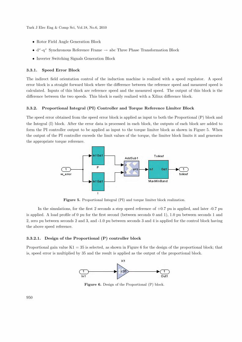
the Integral (I) block. After the error data is processed in each block, the outputs of each block are added toform the PI controller output to be applied as input to the torque limiter block as shown in Figure 5. Whenthe output of the PI controller exceeds the limit values of the torque, the limiter block limits it and generatesthe appropriate torque reference.
Figure 5. Proportional Integral (PI) and torque limiter block realization.
In the simulations, for the first 2 seconds a step speed reference of +0.7 pu is applied, and later -0.7 puis applied. A load profile of 0 pu for the first second (between seconds 0 and 1), 1.0 pu between seconds 1 and2, zero pu between seconds 2 and 3, and -1.0 pu between seconds 3 and 4 is applied for the control block havingthe above speed reference.
3.3.2.1. Design of the Proportional (P) controller block
Proportional gain value K1 = 35 is selected, as shown in Figure 6 for the design of the proportional block; thatis, speed error is multiplied by 35 and the result is applied as the output of the proportional block.
Figure 6. Design of the Proportional (P) block.
950
AKIN, ALAN: The use of FPGA in field-oriented control of an induction machine,
3.3.2.2. Design of the Integral (I) controller block
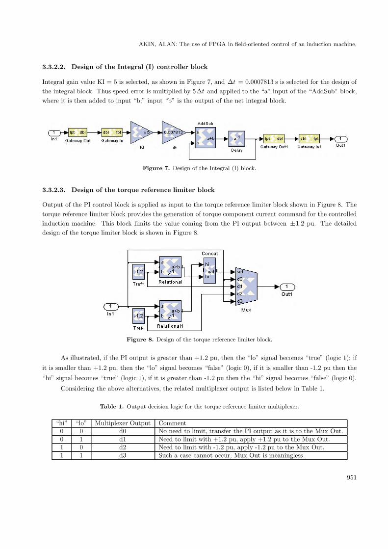
Integral gain value KI = 5 is selected, as shown in Figure 7, and Δt = 0.0007813 s is selected for the design ofthe integral block. Thus speed error is multiplied by 5Δt and applied to the “a” input of the “AddSub” block,where it is then added to input “b;” input “b” is the output of the net integral block.
Figure 7. Design of the Integral (I) block.
3.3.2.3. Design of the torque reference limiter block
Output of the PI control block is applied as input to the torque reference limiter block shown in Figure 8. Thetorque reference limiter block provides the generation of torque component current command for the controlledinduction machine. This block limits the value coming from the PI output between ±1.2 pu. The detaileddesign of the torque limiter block is shown in Figure 8.
Figure 8. Design of the torque reference limiter block.
As illustrated, if the PI output is greater than +1.2 pu, then the “lo” signal becomes “true” (logic 1); if
it is smaller than +1.2 pu, then the “lo” signal becomes “false” (logic 0), if it is smaller than -1.2 pu then the
“hi” signal becomes “true” (logic 1), if it is greater than -1.2 pu then the “hi” signal becomes “false” (logic 0).
Considering the above alternatives, the related multiplexer output is listed below in Table 1.
Table 1. Output decision logic for the torque reference limiter multiplexer.
“hi” “lo” Multiplexer Output Comment0 0 d0 No need to limit, transfer the PI output as it is to the Mux Out.0 1 d1 Need to limit with +1.2 pu, apply +1.2 pu to the Mux Out.1 0 d2 Need to limit with -1.2 pu, apply -1.2 pu to the Mux Out.1 1 d3 Such a case cannot occur, Mux Out is meaningless.
951
Turk J Elec Eng & Comp Sci, Vol.18, No.6, 2010
3.3.3. Rotor field angle generation block
The block which is designed to generate the rotor field angle shown in Figure 4 as “teta” block is composed ofthree Xilinx sub-blocks. The general view of rotor field angle calculator block is shown in Figure 9.
Figure 9. Detail design of the Teta block in Figure 4. Block converts mechanical rotor field angle θe to the electrical
angle information.
One of the sub-blocks called as “swe” takes the torque component current command as input, andgenerates the electrical slip-frequency related angle, θs , assuming constant and rated flux-linkage level for themachine. This block is shown in Figure 10 and will be explained more in detail later.
�
���
����������
���
�
����
���������
����������
���
�
����
���������
�����
���
�
����
����
����!������
"�!����
#$ ���
%��&�'(��
��� #$
%��&�'(�� ��
)���'�
* +
���,
�-.�/��0
����
-.�/��0
����
. 1/�,
���,
� �0.2
����
���������3�
�
�
�
4��5���
�
��
Figure 10. Detail design of the block labeled swe in Figure 9; also may be known as the Electrical Slip-Frequency
Related Angle Generation Block.
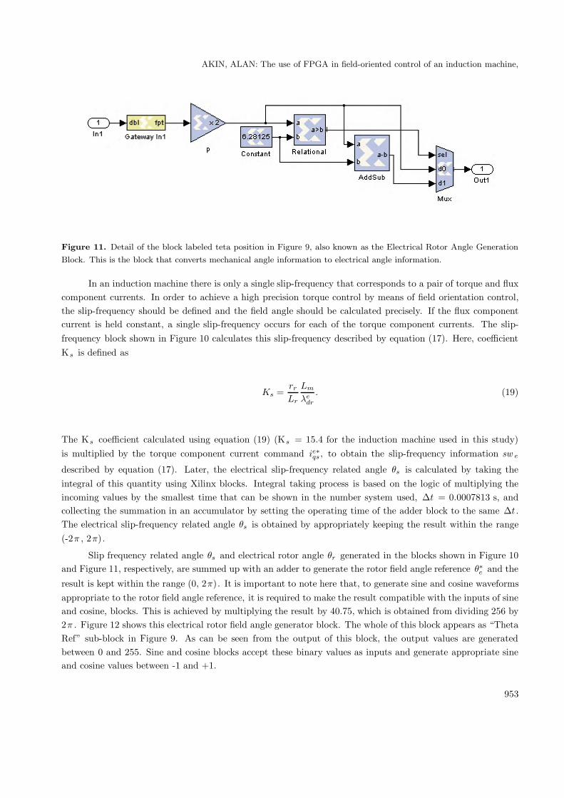
The other sub-block called as “teta position” in Figure 9 takes the mechanical angle information andconverts it to the electrical angle information. This block is shown in Figure 11. Here, the mechanical angleinformation coming from the encoder is multiplied by 2 which is the pole pair number for the machine considered.Since the result would overflow and be out of 2π range in some cases, the correct value for the electrical angleis generated between 0 and 2π range by means of Xilinx comparator and subtracter blocks.
952
AKIN, ALAN: The use of FPGA in field-oriented control of an induction machine,
Figure 11. Detail of the block labeled teta position in Figure 9, also known as the Electrical Rotor Angle Generation
Block. This is the block that converts mechanical angle information to electrical angle information.
In an induction machine there is only a single slip-frequency that corresponds to a pair of torque and fluxcomponent currents. In order to achieve a high precision torque control by means of field orientation control,the slip-frequency should be defined and the field angle should be calculated precisely. If the flux componentcurrent is held constant, a single slip-frequency occurs for each of the torque component currents. The slip-frequency block shown in Figure 10 calculates this slip-frequency described by equation (17). Here, coefficientKs is defined as
Ks =rr
Lr
Lm
λedr
. (19)
The Ks coefficient calculated using equation (19) (Ks = 15.4 for the induction machine used in this study)is multiplied by the torque component current command ie∗qs, to obtain the slip-frequency information sw e
described by equation (17). Later, the electrical slip-frequency related angle θs is calculated by taking theintegral of this quantity using Xilinx blocks. Integral taking process is based on the logic of multiplying theincoming values by the smallest time that can be shown in the number system used, Δt = 0.0007813 s, andcollecting the summation in an accumulator by setting the operating time of the adder block to the same Δt .The electrical slip-frequency related angle θs is obtained by appropriately keeping the result within the range(-2π , 2π).
Slip frequency related angle θs and electrical rotor angle θr generated in the blocks shown in Figure 10and Figure 11, respectively, are summed up with an adder to generate the rotor field angle reference θ∗e and the
result is kept within the range (0, 2π). It is important to note here that, to generate sine and cosine waveformsappropriate to the rotor field angle reference, it is required to make the result compatible with the inputs of sineand cosine, blocks. This is achieved by multiplying the result by 40.75, which is obtained from dividing 256 by2π . Figure 12 shows this electrical rotor field angle generator block. The whole of this block appears as “ThetaRef” sub-block in Figure 9. As can be seen from the output of this block, the output values are generatedbetween 0 and 255. Sine and cosine blocks accept these binary values as inputs and generate appropriate sineand cosine values between -1 and +1.
953
Turk J Elec Eng & Comp Sci, Vol.18, No.6, 2010
Figure 12. Electrical Rotor Field Angle Generator Block (detail of the block labeled Teta Ref in Figure 9); where
θ∗c = θs + θr .
The following equation summarizes the relation between the θe in radians and θ∗e in binary format:
θ∗e = θe2THETA−WIDTH
2π= θe
28
2π= θe
2562π
. (20)
Parameter θe , which has radian unit, is the output of the block labeled “AddSub1” in Figure 12. To convert
the θe in radians to binary format, θe is multiplied by 2THETA−WIDTH and divided by 2π . The THETA −WIDTH in our case is 8-bit, so 28 is equal to 256.
The sine and cosine blocks receive θ∗e in binary format as input and generate sine and cosine valuesaccording to the relation
[ −θ∗e2OUTPUT WIDTH−2
,+θ∗e
2OUTPUT WIDTH−2=
−θ∗e28
,+θ∗e28
=−θ∗e256
,+θ∗e256
]. (21)
3.3.4. Transformation block from the d, q synchronous reference frame to the a, b, c statorreference frame: (de , qe) → (a, b, c)
The transform block from the d, q synchronous reference frame to the a, b, c stator reference frame, denotedby the sub-block labeled “Spartan-3” in Figure 3, is shown in Figure 4 as the “DQ-ABC2” sub-block.
The sub-blocks required to complete the transformation are shown in Figure 13. One of these sub-blocksis labeled “Sincos” and the other is labeled “Subsystem.”
Figure 13. Sub-blocks required to complete the dq-abc transformation (DQ-ABC2 Block in Figure 4).
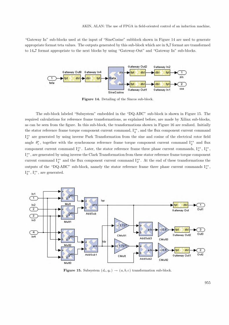
“Sincos” sub-block shown in Figure 13 generates sin(θ) and cos(θ) outputs that corresponds to the input“teta” values which vary in between 0 and 256, as explained in the “tetaref” sub-block. “Gateway-Out” and
954
AKIN, ALAN: The use of FPGA in field-oriented control of an induction machine,
“Gateway In” sub-blocks used at the input of “SineCosine” subblock shown in Figure 14 are used to generateappropriate format teta values. The outputs generated by this sub-block which are in 9 7 format are transformedto 14 7 format appropriate to the next blocks by using “Gateway-Out” and “Gateway In” sub-blocks.
Figure 14. Detailing of the Sincos sub-block.
The sub-block labeled “Subsystem” embedded in the “DQ-ABC” sub-block is shown in Figure 15. Therequired calculations for reference frame transformations, as explained before, are made by Xilinx sub-blocks,as can be seen from the figure. In this sub-block, the transformations shown in Figure 16 are realized. Initiallythe stator reference frame torque component current command, Is∗
q , and the flux component current command
Is∗d are generated by using inverse Park Transformation from the sine and cosine of the electrical rotor field
angle θ∗e , together with the synchronous reference frame torque component current command Ie∗q and flux
component current command Ie∗d . Later, the stator reference frame three phase current commands, Is∗
a , Is∗b ,
Is∗c , are generated by using inverse the Clark Transformation from these stator reference frame torque component
current command Is∗q and the flux component current command Is∗
d . At the end of these transformations the
outputs of the “DQ-ABC” sub-block, namely the stator reference frame three phase current commands Is∗a ,
Is∗b , Is∗
c , are generated.
Figure 15. Subsystem (de, qe ) → (a, b, c) transformation sub-block.
955
Turk J Elec Eng & Comp Sci, Vol.18, No.6, 2010
������ 6��*7���#������
������ ���*7���#������
� ���
� ���
� ���
� ���
� ���
��
� ���
� ���
Figure 16. The function of the “Subsystem” sub-block.
If the generated a, b, c phase current commands are processed by comparing them with the measured anddigitized a, b, c phase currents in the Hysteresis Control Sub-block, shown in Figure 17, the inverter switchingsignals at the output are generated. Initially the difference between the command and the measured currentsare obtained, later these differences are applied to the inputs of the sub-blocks which contribute to hysteresiscontrol, and logic-1 or logic-0 level signals are generated at the outputs to achieve the appropriate switching.
�
���
��
���
���
5���'���,
��
���
���
5���'����
��
���
���
5���'���
���
#$ ���
%��&�' ��8
#$ ���
%��&�' ��/
#$ ���
%��&�' ��1
#$ ���
%��&�'(��-
#$ ���
%��&�' ��0
#$ ���
%��&�' ��2
#$ ���
%��&�' ��,
#$ ���
%��&�' ���
#$ ���
%��&�' ����
#$ ���
%��&�' ���
#$ ���
%��&�' ���
#$ ���
%��&�'(��
��� #$
%��&�'(�8
��� #$
%��&�'(�/
��� #$
%��&�'(�1
��� #$
%��&�'(�-
��� #$
%��&�'(�0
��� #$
%��&�'(�2
��� #$
%��&�'(�,
��� #$
%��&�'(��
��� #$
%��&�'(���
��� #$
%��&�'(��
��� #$
%��&�'(��
��� #$
%��&�'(�
�����������
�
�
�
9����,
�����������
�
�
�
9�����
�����������
�
�
�
9�����
��
��
�
��
�
��
Figure 17. Hysteresis control sub-block.
Figure 18. The “Subsystem” sub-blocks appearing in Figure 17 form the hysteresis control for a single phase.
It is worth to note here that although the switching signals are at 400 kHz in this block, the frequencyis reduced to 20 kHz in the Hysteresis Control Block by appropriate gateway connections. This value can bechanged and adjusted to any other value by the user.
956
AKIN, ALAN: The use of FPGA in field-oriented control of an induction machine,
3.4. Simulation of the system modeled in Matlab Simulink with the controller
embedded into a Xilinx Spartan-3 FPGA designed using the Xilinx system
generator
The indirect field-oriented controlled induction machine, whose controller is embedded into a Xilinx Spartan-3Field Programmable Gate Array (FPGA) by means of the Xilinx System Generator Toolbox, is simulated via acomplete system modeled in Matlab Simulink environment, as shown in Figure 3. Design details of the controllerdeveloped using Xilinx System Generator are provided in the preceding sections.
The induction machine is initially operated as a motor with a 0.7 pu speed reference applied during thefirst 2 seconds and -0.7 pu for the next 2.5 seconds. The machine is operated at no load during the first second,then it is loaded with 1.0 pu load during the next second, it is unloaded for the following 1.5 seconds, and loadedwith -1.0 pu for the last second of simulation time interval. The actual speed obtained from the simulation isshown in Figure 19. It is important to note that the signals are represented in per unit (pu) values in simulationsand it is required to multiply them by their respective base values to be able to find the corresponding realvalues.
.0 � �.0 � �.0 , ,.0 2 2.0� ./
� .-
� .2
� .�
.�
.2
.-
./
Figure 19. The actual speed for the simulated indirect field oriented controlled.
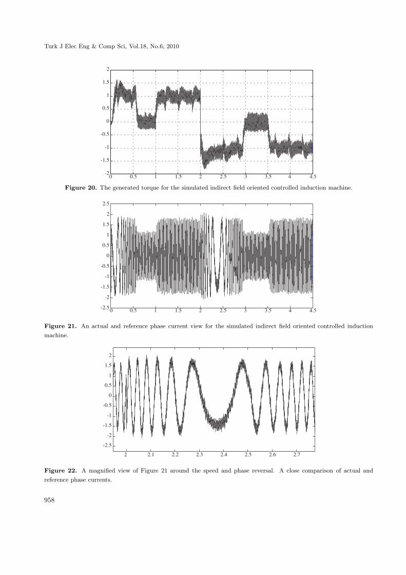
To be able to achieve the related speed regulation a torque reference is generated and regulated dependingon the load torque applied. Figure 20 shows the load torque versus generated torque of the machine for theoperation described above.
For the same operating conditions, the reference and the actual machine currents are provided in Figure21. A magnified view of these currents around the speed and phase reversal of the machine is given in Figure22.
The resources spent for the related design in Spartan 3 xc3s200 FPGA board can be observed after thesimulation is run by using the resource estimator block. For the design used in this study, resources spent arelisted in Table 2 with the results represented in percentage of total related resources.
957
Turk J Elec Eng & Comp Sci, Vol.18, No.6, 2010
.0 � �.0 � �.0 , ,.0 2 2.0��
��.0
��
� .0
.0
�
�.0
�
Figure 20. The generated torque for the simulated indirect field oriented controlled induction machine.
.0 � �.0 � �.0 , ,.0 2 2.0��.0
��
��.0
��
� .0
.0
�
�.0
�
�.0
Figure 21. An actual and reference phase current view for the simulated indirect field oriented controlled induction
machine.
� �.� �.� �., �.2 �.0 �.- �.1
��.0
��
��.0
��
� .0
.0
�
�.0
�
Figure 22. A magnified view of Figure 21 around the speed and phase reversal. A close comparison of actual and
reference phase currents.
958
AKIN, ALAN: The use of FPGA in field-oriented control of an induction machine,
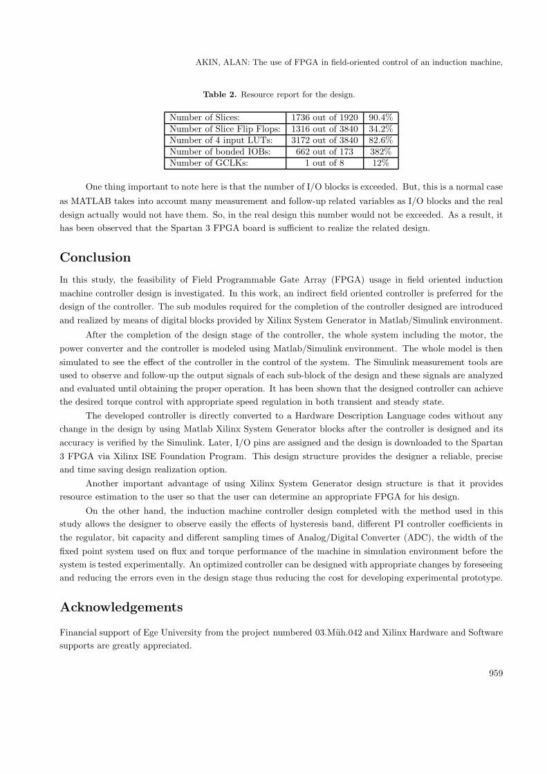
Table 2. Resource report for the design.
Number of Slices: 1736 out of 1920 90.4%Number of Slice Flip Flops: 1316 out of 3840 34.2%Number of 4 input LUTs: 3172 out of 3840 82.6%Number of bonded IOBs: 662 out of 173 382%Number of GCLKs: 1 out of 8 12%
One thing important to note here is that the number of I/O blocks is exceeded. But, this is a normal case
as MATLAB takes into account many measurement and follow-up related variables as I/O blocks and the realdesign actually would not have them. So, in the real design this number would not be exceeded. As a result, ithas been observed that the Spartan 3 FPGA board is sufficient to realize the related design.
Conclusion
In this study, the feasibility of Field Programmable Gate Array (FPGA) usage in field oriented inductionmachine controller design is investigated. In this work, an indirect field oriented controller is preferred for thedesign of the controller. The sub modules required for the completion of the controller designed are introducedand realized by means of digital blocks provided by Xilinx System Generator in Matlab/Simulink environment.
After the completion of the design stage of the controller, the whole system including the motor, thepower converter and the controller is modeled using Matlab/Simulink environment. The whole model is thensimulated to see the effect of the controller in the control of the system. The Simulink measurement tools areused to observe and follow-up the output signals of each sub-block of the design and these signals are analyzedand evaluated until obtaining the proper operation. It has been shown that the designed controller can achievethe desired torque control with appropriate speed regulation in both transient and steady state.
The developed controller is directly converted to a Hardware Description Language codes without anychange in the design by using Matlab Xilinx System Generator blocks after the controller is designed and itsaccuracy is verified by the Simulink. Later, I/O pins are assigned and the design is downloaded to the Spartan3 FPGA via Xilinx ISE Foundation Program. This design structure provides the designer a reliable, preciseand time saving design realization option.
Another important advantage of using Xilinx System Generator design structure is that it providesresource estimation to the user so that the user can determine an appropriate FPGA for his design.
On the other hand, the induction machine controller design completed with the method used in thisstudy allows the designer to observe easily the effects of hysteresis band, different PI controller coefficients inthe regulator, bit capacity and different sampling times of Analog/Digital Converter (ADC), the width of thefixed point system used on flux and torque performance of the machine in simulation environment before thesystem is tested experimentally. An optimized controller can be designed with appropriate changes by foreseeingand reducing the errors even in the design stage thus reducing the cost for developing experimental prototype.
Acknowledgements
Financial support of Ege University from the project numbered 03.Muh.042 and Xilinx Hardware and Softwaresupports are greatly appreciated.
959
Turk J Elec Eng & Comp Sci, Vol.18, No.6, 2010
References
[1] BPRA043, “Digital Signal Processing Solution for AC Induction Motor Application Note”, Texas Instruments Inc.,
www.ti.com, 1996.
[2] BPRA073, “Field Orientated Control of 3-Phase AC-Motors Literature ′′, Texas Instruments Europe Inc.,
www.ti.com, 1998.
[3] B. Hariram, N. S. Marimuthu, “A VHDL Library of Modules for Vector Control of Induction Motor”, International
Journal of Electrical and Power Engineering 1 (2), pp. 225-259, Medwell Journals, 2007.
[4] U. Baader, M. Depenbrock, G. Gierse, “Direct self control (DSC) of inverter-fed-induction machine, a basis for
speed control without speed measurement”, IEEE Transaction on Industrial Applications, Vol 28, pp. 581- 588,
1992.
[5] “Direct self-control of the flux and rotary moment of a rotary-field machine”, U.S. Patent 4 678 248., 1987.
[6] I. Takahashi, T. Noguchi, “A new quick response and high efficiency control strategy of an induction machine”,
IEEE Transactions on Industrial Applications, Vol. 22: pp. 820-827, 1986.
[7] S. K. Sahoo, G. T. R. Das, V. Subrahmanyam, “Implementation and Simulation of Direct Torque Control Scheme
with the Use of FPGA Circuit”, ARPN Journal of Engineering and Applied Sciences, Vol. 3, No. 2, ISSN: 1819-6608,
2008.
[8] K. Tazi, E. Monmasson, “Single-Chip DSP Based Speed Control of Two AC-Machine”, Speedam, Sorrento (Italy),
pp. P4-33 to P4-38, 1998.
[9] A. Aounis, S. E. Cirstea, M. N. Cirstea, “Reusable VHDL Architectures for Induction Motor PWM Vector Control,
Targeting FPGAs”, IEEE, 2006.
[10] J. Vasarhelyi, M. Imecs, C. Szabo, I. I. Incze, T. Adam, “FPGA Implementation of the Reconfigurable Control
System for AC Drives Fed by Tandem Converter”, 2005.
[11] J. F. Herbert, S. Beierke, “Universal PWM-Unit with DSP Interface realized in a TI-FPGA 1280”, Texas Instru-
ments 1994.
[12] M. Cirstea, A. Aounis, M. Mccormick, “Rapid Prototyping of Induction Motor Vector Control System Based
on Reusable VHDL Digital Architectures and FPGA Implementation”, PCIM 2002 Power Electronics Intelligent
Motion Power Quality, Nuremberg, Germany, pp. 199-203, May 14-16, 2002.
[13] M. Imecs, I. I. Incze, Vasarhelyi J., Cs. Szabo, “Tandem Converter Fed Induction Motor Drive Controlled With Re-
Configurable Vector Control System”, PCIM 2001 Power Electronics Intelligent Motion Power Quality, Nuremberg,
Germany, pp. 341-346, June 19-21, 2001.
[14] P. Poure, F. Aubepart, F. Braun, “ICs for real time Motion Control: A design methodology for rapid
prototyping ′′ ,PCIM 2001 Power Electronics Intelligent Motion Power Quality, Nuremberg, Germany, pp. 211-216,
June 19-21, 2001.
[15] K. Tazi, E. Monmasson, J. P. Louis, “Description of an entirely reconfigurable Architecture Dedicated to the Current
Vector Control of a Set of AC Machines”, Proceedings of IECON’99, pp.1415-1420, 1999.
960
AKIN, ALAN: The use of FPGA in field-oriented control of an induction machine,
[16] S. Ferreira, F. Haffner, L. F. Pereira, F. Moraes, “Design and Prototyping of Direct
[17] Torque Control of Induction Motors in FPGAs”, Proceedings of the 16th Symposium on Integrated Circuits and
Systems Design (SBCCI’03), IEEE, 2003.
[18] F. AubBpart, P. Poure, C. Girerd, Y.A. Chapuis, F. Braun, “Design and Simulation of ASIC-based System Control:
Application to Direct Torque Control of Induction Machine”, ISIE’99 Bled, Slovenia, IEEE, 1999.
[19] S. J. Kim, H. J. Lee, S. K. Kim, Y. A. Kwon, “ASIC Design for DTC Based Speed Control of Induction Motor”,
ISIE 2001, Pusan, Korea, IEEE, 2001.
[20] T. Takahashi, J. Goetz, “Implementation of Complete AC Servo Control in a Low Cost FPGA and Subsequent
ASSP Conversion”, IEEE, 2004.
[21] G. G. Parma, V. Dinavahi, “Real-Time Digital Hardware Simulation of Power Electronics and Drives”, IEEE
Transactions on Power Delivery, Vol. 22, No. 2, pp.1235-1246, 2007.
[22] J. Vasarhelyi, M. Imecs, C. Szabo, Ioan Iov Incze, “FPGA Implementation Vector Control Of Tandem Converter
Fed Induction Machine”, In 6 th International Symposium of Hungarian, Researchers on Computational Intelligence,
Budapest, Magyar, 2005.
[23] J. G. Mailloux, S. Simard, R. Beguenane, “Implementation Of Division And Square Root Using XSG for FPGA
Based Vector Control Drives”, International Journal of Electrical and Power Engineering 1 (5); pp. 524-529; 2007;
ISSN: 1990-7958, Medwell Journals, 2007.
[24] F. Ricci, H. L. Luy, “Modeling and Simulation of FPGA Based Variable-Speed Drives Using Simulink”, Mathematics
and Computers in Simulation, Volume 63, Issue 3-5, pp. 183-195, ISSN: 0378-4754, 2003.
[25] M. Ownby, W. H. Mahmoud, “A Design Methodology for Implementing DSP with Xilinx System Generator for
Matlab”, IEEE, 2002.
[26] J. Ou, V. K. Prasanna, “Pygen: A MATLAB/Simulink Based Tool For Synthesizing Parameterized and Energy
Efficient Designs Using FPGAs”, Proceedings of the 12th Annual IEEE Symposium on Field-Programmable Custom
Computing Machines (FCCM’04), IEEE, 2004.
[27] A. Fakhfakh, S. Feki, Y. Herve, A. Walha, N. Masmoudi, “Virtual Prototyping in Power Electronics Using VHDL-
AMS Application to the Direct Torque Control Optimisation”, Journal of Applied Sciences 6 (3): pp. 572-579,
ISSN:1812-5654, Assian Network for Scientific Information, 2006.
[28] O. Akın, “The Use of FPGA in Field Oriented Control of an Induction Machine” M. Sc. Thesis, Ege University
Natural and Applied Science Institute, 2005.
[29] J. M. Loehrke, “A Digital Implementation of Feed-forward Field Oriented Control ′′ , Master of Science Thesis,
University of Wisconsin-Madison, Electrical Engineering Department, 1985.
[30] Xilinx Corp., “Xilinx System Generator v2.1 Reference Guide for Simulink ′′ , www.xilinx.com.
[31] M. N. Cirstea, A. Dinu, J. Khor, M. McCormick, “Neural and Fuzzy Logic Control of Drives and Power
Systems ′′ ,Elsevier Science Ltd., Oxford, 2002.
961
Turk J Elec Eng & Comp Sci, Vol.18, No.6, 2010
[32] M. P. Kazmierkowski, R. Krishnan, F. Blaabjerg, J. D. Irwin, “Control in Power Electronics: Selected
Problems ′′,Academic Press, 2002.
[33] A. Karabıyık, “Implementation of a Wavelet Neural Network Using Field Programmable Gate Array”, M. Sc.
Thesis, Ege University Natural and Applied Science Institute, 2005.
[34] T. A. Lipo, D. W. Novotny, Vector Control and Dynamics of AC Drives, 1st Ed., New York, Oxford University
Press, 1996.
[35] S. Redpath, “Vector control of AC motors using low-cost MCUs ′′ , NEC Electronics Corp., 2003.
[36] G. S. Roberts, “Design and Implementation of a Three-Phase Induction Motor Control Scheme ′′ , Thesis Project,
Department of Information Technology and Electrical Engineering, the University of Queensland, 2001.
[37] M. Cirstea, A. Aounis, M.McCormick, P. Urwin, L. Haydock; “Induction Motor Drive System Modeled in VHDL”,
IEEE, 2000.
[38] F. Ricci, H. L. Luy, “An FPGA-Based Rapid Prototyping Platform for Variable-Speed Drives”, Industrial Elec-
tronics Society, Vol. 2, pp. 1156-1161, IEEE, 2002.