152
The White Book of ELI Nuclear Physics Bucharest-Magurele, Romania The ELI-Nuclear Physics working groups
The White Book of ELI Nuclear Physics
Bucharest-Magurele, Romania
The ELI-Nuclear Physics working groups
Contents
1 Foreword 4
2 Executive Summary 52.1 Basic Objectives . . . . . . . . . . . . . . . . . . . . . . . . . . . . . . . . . . . . . . . 52.2 The Scientific Case of ELI-Nuclear Physics . . . . . . . . . . . . . . . . . . . . . . . . 6
3 Conceptual Design Report for the multi-PW laser systemat ELI Nuclear Physics Facility 113.1 Introduction . . . . . . . . . . . . . . . . . . . . . . . . . . . . . . . . . . . . . . . . . . 113.2 Laser Architecture and Technical Layout . . . . . . . . . . . . . . . . . . . . . . . . . . 12
3.2.1 Introduction . . . . . . . . . . . . . . . . . . . . . . . . . . . . . . . . . . . . . 123.2.2 Direction of implementation . . . . . . . . . . . . . . . . . . . . . . . . . . . . . 133.2.3 Front end . . . . . . . . . . . . . . . . . . . . . . . . . . . . . . . . . . . . . . . 143.2.4 High rep rate PW amplifiers . . . . . . . . . . . . . . . . . . . . . . . . . . . . 183.2.5 High energy amplifiers . . . . . . . . . . . . . . . . . . . . . . . . . . . . . . . . 193.2.6 ELI-NP multi-PW laser system conceptual design . . . . . . . . . . . . . . . . 203.2.7 ELI-NP laser building sketch . . . . . . . . . . . . . . . . . . . . . . . . . . . . 21
3.3 Pulse Compression . . . . . . . . . . . . . . . . . . . . . . . . . . . . . . . . . . . . . . 223.4 Alignment and Diagnostics . . . . . . . . . . . . . . . . . . . . . . . . . . . . . . . . . 233.5 Pulse shaping . . . . . . . . . . . . . . . . . . . . . . . . . . . . . . . . . . . . . . . . . 243.6 Control, supervision system (C2S) . . . . . . . . . . . . . . . . . . . . . . . . . . . . . 243.7 Coherent beam combining . . . . . . . . . . . . . . . . . . . . . . . . . . . . . . . . . . 263.8 Laser Beam Transport System . . . . . . . . . . . . . . . . . . . . . . . . . . . . . . . 273.9 Further infrastructure . . . . . . . . . . . . . . . . . . . . . . . . . . . . . . . . . . . . 27References . . . . . . . . . . . . . . . . . . . . . . . . . . . . . . . . . . . . . . . . . . . . . . 29Glosary . . . . . . . . . . . . . . . . . . . . . . . . . . . . . . . . . . . . . . . . . . . . . . . 30
4 Infrastructure Producing High Intensity Gamma Raysfor ELI Nuclear Physics Pillar 324.1 Introduction . . . . . . . . . . . . . . . . . . . . . . . . . . . . . . . . . . . . . . . . . 324.2 First stage warm linac in X-band RF plus 532nm laser . . . . . . . . . . . . . . . . . 33
4.2.1 Description . . . . . . . . . . . . . . . . . . . . . . . . . . . . . . . . . . . . . . 334.2.2 Specifications of the ELI-NP machine . . . . . . . . . . . . . . . . . . . . . . . 394.2.3 Possible upgrade in future . . . . . . . . . . . . . . . . . . . . . . . . . . . . . . 41
4.3 Second stage 100 mA Energy Recovery Linac . . . . . . . . . . . . . . . . . . . . . . . 414.4 Conclusions . . . . . . . . . . . . . . . . . . . . . . . . . . . . . . . . . . . . . . . . . . 42References . . . . . . . . . . . . . . . . . . . . . . . . . . . . . . . . . . . . . . . . . . . . . . 43Glosary . . . . . . . . . . . . . . . . . . . . . . . . . . . . . . . . . . . . . . . . . . . . . . . 44
5 The Scientific Case of ELI Nuclear Physic Pillar 485.1 Introduction to Envisioned Experiments at ELI Nuclear Physics Facility . . . . . . . . 485.2 Experiments with the APOLLON-type Laser used stand-alone . . . . . . . . . . . . . 49
1

5.2.1 Production of Neutron-Rich Nuclei around the N = 126 Waiting Pointof the r-Process via the Fission-Fusion Reaction Mechanismusing a Laser-Accerated Th Beam . . . . . . . . . . . . . . . . . . . . . . . . . 49
5.2.2 From Radiation Pressure Acceleration (RPA) and Laser-Driven Ion Pistonsto Direct Laser Acceleration of Protons at Intensities up to 1024W/cm2 . . . . 51
5.2.3 Deceleration of Very Dense Electron and Ion Beams . . . . . . . . . . . . . . . 535.2.4 The development and application of ultra-short duration high brilliance
gamma rays probes for nuclear physics . . . . . . . . . . . . . . . . . . . . . . . 555.2.5 A Relativistic Ultra-thin Electron Sheet used as a Relativistic Mirror
for the Production of Brilliant, Intense Coherent γ-Rays . . . . . . . . . . . . . 565.2.6 Nuclear Techniques for Characterization of Laser-Induced Radiations . . . . . . 585.2.7 Modelling of High-Intensity Laser Interaction with Matter . . . . . . . . . . . . 625.2.8 Studies of enhanced decay of 26Al in hot plasma environments . . . . . . . . . 645.2.9 Nuclear phases and symmetries . . . . . . . . . . . . . . . . . . . . . . . . . . . 66
5.3 APOLLON-Type Laser + γ/e− Beam . . . . . . . . . . . . . . . . . . . . . . . . . . . 695.3.1 Probing the Pair Creation from the Vacuum in the Focus of
Strong Electrical Fields with a High Energy γ Beam . . . . . . . . . . . . . . 695.3.2 The Real Part of the Index of Refraction of the Vacuum
in High Fields: Vacuum Birefringence . . . . . . . . . . . . . . . . . . . . . . . 725.3.3 Cascades of e+e− Pairs and γ-Rays triggered by
a Single Slow Electron in Strong Fields . . . . . . . . . . . . . . . . . . . . . . 745.3.4 Compton Scattering and Radiation Reaction
of a Single Electron at High Intensities . . . . . . . . . . . . . . . . . . . . . . . 805.3.5 Nuclear Lifetime Measurements by Streaking Conversion
Electrons with a Laser Field. . . . . . . . . . . . . . . . . . . . . . . . . . . . . 875.4 Stand-alone γ/e− Facility for Nuclear Spectroscopy . . . . . . . . . . . . . . . . . . . 90
5.4.1 Measuring Narrow Doorway States, embedded in Regions of High Level Densityin the First Nuclear Minimum, which are identified by specific(γ, f), (γ, α), (γ, p), (γ, n) Reactions and allow to map out theNuclear Potential Landscape . . . . . . . . . . . . . . . . . . . . . . . . . . . . 90
5.4.2 Precision Tests of Fluctuating Quantities in Nuclear Physics of Highly ExcitedNuclear Levels in Comparison to Random-Matrix-Theory and Quantum Chaos 91
5.4.3 Precision measurement of the dipole polarizability αD of 208Pbwith high intensity, monoenergetic MeV γ-radiation for the evaluationof neutron skin and the enhancement of UNEDF theory . . . . . . . . . . . . . 93
5.4.4 Use of high-resolution inelastic electron scattering to investigatedeformed nuclear shapes and the scissors mode . . . . . . . . . . . . . . . . . . 95
5.4.5 Parity violation in a (e, e′
) process . . . . . . . . . . . . . . . . . . . . . . . . . 975.4.6 Nuclear Transitions and Parity-violating Meson-Nucleon Coupling . . . . . . . 1025.4.7 Study of pygmy and giant dipole resonances in lead isotopes by direct γ excitation1045.4.8 Gamma scattering on nuclei
The Pygmy Dipole Resonance (PDR) of deformed nuclei . . . . . . . . . . . . . 1055.4.9 Fine-structure of Photo-response above the Particle Threshold:
the (γ ,α), (γ,p) and (γ ,n) Reactions . . . . . . . . . . . . . . . . . . . . . . . 1105.4.10 Nuclear Resonance Fluorescence on Rare Isotopes and Isomers . . . . . . . . . 1145.4.11 Multiple Nuclear Excitons . . . . . . . . . . . . . . . . . . . . . . . . . . . . . . 115
5.5 Stand-alone γ/e− Facility for Astrophysics . . . . . . . . . . . . . . . . . . . . . . . . 1175.5.1 Neutron Capture Cross Section of s-Process Branching Nuclei with Inverse
Reactions . . . . . . . . . . . . . . . . . . . . . . . . . . . . . . . . . . . . . . . 1175.5.2 Measurements of (γ, p) and (γ, α) Reaction Cross Sections for p-Process Nucle-
osynthesis . . . . . . . . . . . . . . . . . . . . . . . . . . . . . . . . . . . . . . . 1195.6 Applications and Industry Relevant Developments at ELI-NP . . . . . . . . . . . . . 121
5.6.1 Industrial Applications for the Management of Nuclear Materials . . . . . . . . 1215.6.2 Radioscopy and Tomography . . . . . . . . . . . . . . . . . . . . . . . . . . . . 126
2
5.6.3 High Resolution, high Intensity X-Ray Beam . . . . . . . . . . . . . . . . . . . 1285.6.4 Producing of medical isotopes via the (γ, n) reaction . . . . . . . . . . . . . . 1325.6.5 Medical Radioisotopes produced by γ Beams . . . . . . . . . . . . . . . . . . . 1325.6.6 Extremely BRIlliant Neutron-Source produced via the (γ, n) Reaction
without Moderation (BRIN) . . . . . . . . . . . . . . . . . . . . . . . . . . . . 1355.6.7 Neutron diffraction techniques for materials science . . . . . . . . . . . . . . . . 1365.6.8 Dual-range Instrumentation for Wide Applicability Neutron Techniques . . . . 1385.6.9 Intense BRIlliant Positron-Source produced via the (γ, e+e−) Reaction (BRIP) 1405.6.10 Intense BRIlliant Positron-Source: Positrons in Applied Physics . . . . . . . . 1405.6.11 Positron-excited Auger Electron Spectroscopy (PAES) . . . . . . . . . . . . . . 1415.6.12 Positron Annihilation Spectroscopy (PAS) . . . . . . . . . . . . . . . . . . . . . 1445.6.13 AGPAS technique with high energy gamma beams . . . . . . . . . . . . . . . . 1475.6.14 Testing of radiation effects on commercial optical fibers . . . . . . . . . . . . . 1485.6.15 Materials research in high intensity radiation fields . . . . . . . . . . . . . . . . 148
3
1 Foreword
This report contains a comprehensive description of the new international research infrastructure, theExtreme Light Infrastructure - Nuclear Physics facility (ELI-NP), emphasizing the physics which canbe addressed with it. The report has been prepared from contributions by many people from variouslaboratories throughout the world. Their contributions have be merged by a group of editors. This re-port at the same time demonstrates that ELI-NP can count on a large international user community.Here the extreme light infrastructure consisting of two components: a very high intensity laser system(10-30 PW) and a very brilliant, intense γ beam of up to 19 MeV, 0.1 % band width and 1013γ/s .With this report we demonstrate our deep conviction that this infrastructure will create a new Euro-pean laboratory with a broad range of science covering new nuclear physics, astrophysics, fundamentalhigh field physics as well as applications in nuclear materials, radioactive waste management, materialscience and life sciences.
For the realization of ELI-NP we envisage the design of the facility to allow a flexible layout of theexperiments and the possibility for further upgrading according to the available resources. The ELI-NPfacility will be built in such a way to accommodate its future growth, for example:
• to include after 2016 new experiments and to upgrade the laser power and gamma beam intensityand energy
• after 2020 to include the most ambitious and far reaching projects as well as the ones that areyet to be discovered. It may include an upgrade of the γ beam facility, using a superconductingenergy recovery linac reaching to higher intensities of 1015γ/s and improved bandwidth
4

2 Executive Summary
2.1 Basic Objectives
ELI will be the only European and International Centre for high-level research on ultra-high intensitylaser, laser-matter interaction and secondary sources with unparalleled possibilities. Its pulse peakpower and briefness will go beyond the current state-of-the-art by several orders of magnitude. Becauseof its unique properties, this multidisciplinary facility will provide magnificent new opportunities tostudy the fundamental processes unfolded during light-matter interaction.ELI will create a platform, where Extreme Light applications for the benefit of society will be dynam-ically promoted. In its mission ELI will practice a vigorous technology transfer to European SMEsand large firms. High on ELI agenda will be the training of aspiring scientists and engineers in thenumerous disciplines associated with the Extreme Light.The ELI project, a collaboration of 13 European countries, will comprise four pillars:
• High Energy Beam Science devoted to the development and usage of dedicated beam lines withultra short pulses of high energy radiation and particles reaching almost the speed of light (100GeV).This part of ELI will be realized in Prague (Czech Republic)
• Attosecond Laser Science designed to conduct temporal investigation of electron dynamics inatoms, molecules, plasmas and solids at attosecond scale (10−18) sec.Szeged (Hungary) will host the short pulse pillar of ELI.
• Laser-based Nuclear Physics:The third site in Magurele (near Bucharest/Romania) will focus on laser-based nuclear physics.While atomic processes are well suited to the visible or near visible laser radiation, as a thirdpillar ELI-NP will generate radiation and particle beams of higher energy and with brilliancesuited to studies of nuclear and fundamental processes.
• Ultra High Field Science that will explore relativistic laser-matter interaction in an energy rangewhere totally new phenomena like radiation dominated interaction become dominant.The decision on the location of the technologically most challenging pillar will be taken in 2012after validation of the technology.
For ELI-NP it is foreseen to install in the first stage (2011-2015) two arms of the APOLLON-typelaser, each with a power of 10 PW. A highly brilliant γ beam will be generated via the laser interactionwith a brilliant bunched electron beam. Thus ELI-NP will allow either combined experiments betweenthe high-power laser and the γ beam or stand-alone experiments.For the Extreme Light Infrastructure - Nuclear Physics facility (ELI-NP) two new central instrumentsare planned:
1. A very high intensity laser beam, where two 10 PW Apollon-type lasers are coherently added tothe high intensity of 1023 − 1024W/cm2 or electrical fields of 2 · 1015V/m.
2. A very intense, brilliant, very low bandwidth, high-energy γ beam, which is obtained by inco-herent Compton back scattering of a laser light on a very brilliant, intense, classical electronbeam.
This infrastructure will create a new European laboratory with a broad range of science coveringfrontier fundamental physics, new nuclear physics and astrophysics as well as applications in nuclearmaterials, radioactive waste management, material science and life sciences.
5

2.2 The Scientific Case of ELI-Nuclear Physics
In this project we want to use a very high intensity laser and a very brilliant, intense γ beam to achievemajor progress in nuclear physics and its associated fields like the element synthesis in astrophysicsand many new applications or even to observe in fundamental physics the first catalysed pair creationfrom the quantum vacuum.At the Extreme Light Infrastructure - Nuclear Physics facility will be possible to perform eithercombined experiments between the high-power laser and the γ beam or stand-alone experiments usingeach of these major instruments.We should first place the laser developments into the right perspective. Typical nuclear excitationenergies are of the order of 100 keV – 1 MeV and typical nuclear radii are below 10 fm. Thus relevantelectrical field strengths in a nucleus, which change the dynamics, are of the order of 100 keV/(e·10fm)=1019V/m and as such much beyond the Sauter field strength for pair creation from the vacuum of1.3·1018V/m [5]. Since fields beyond the Sauter field cause cascades of e+e− pairs and limit the field tothe Sauter field, it is impossible to reach laser fields which directly influence the internal dynamics ofnuclei significantly. On the other hand, ion acceleration using high power laser allows to produce 1015
times more dense ion beams than achievable with classical acceleration. The cascaded fission-fusionreaction mechanism can then be used to produce very neutron-rich heavy nuclei for the first time.These nuclei allow to investigate the N = 126 waiting point of the r-process in nucleosynthesis. Withthis type of new laser acceleration mechanism very significant contributions to one of the fundamentalproblems of astrophysics, the production of the heavy elements beyond iron in the universe can beaddressed. According to a recent report by the National Research Council of the National Academy ofScience (USA), the origin of the heaviest elements remains one of the 11 greatest unanswered questionsof modern physics [1].The second instrument, the intense, brilliant γ beam, is envisaged to provide a photon flux of I =1013/[s (100 µm)2], or – introducing the maximum Breit-Wigner cross section λ2/π for 5 MeV γ quantaof (≈ 100 fm)2 – a flux of 10−5/[s (100 fm)2], thus demonstrating the limitations by the presentlyachievable photon flux, where e.g. pump-probe experiments will remain impossible. The reflectingrelativistic mirror probably will work at larger wave length. However it is a high risk that the reflectingrelativistic mirror with 1014 photons per shot and (µm)2 will also be realized for MeV energies. If so,double excitation and pump-probe experiments in nuclear physics would become possible for the firsttime. The main achievements with the γ beam facility probably will occur with high resolution athigher nuclear excitation energies. Identifying the new neutron halo isomers closely below the neutronbinding energy would open a new field of nuclear spectroscopy. Thus the nuclear physics experimentshave to be carefully designed and it has to be considered that the success of lasers in atomic physicscannot simply be duplicated in nuclear physics due to the very different scales and dimensions.The γ beam will have unique properties in world wide comparison and opens new possibilities for highresolution spectroscopy at higher nuclear excitation energies. They will lead to a better understandingof nuclear structure at higher excitation energies with many doorway states, their damping widths, andchaotic behaviour, but also new fluctuating properties in the time and energy domain. The detailedinvestigation of the pygmy dipole resonance above and below the particle threshold is very essential fornucleosynthesis in astrophysics. The γ beam also opens many new possibilities for applications. Theγ beam itself can be used to map the isotope distributions of nuclear materials or radioactive wasteremotely via Nuclear Resonance Fluorescence (NRF) measurements [6]. At lower energies around 100keV the high resolution of the beam is very important for protein structural analysis. In addition wewant to produce low energy, brilliant, intense neutron beams and low energy, brilliant, intense positronbeams, which open new fields in material science and life sciences. The possibility to study the sametarget with these very different brilliant beams will be unique and advance science much faster.The high power laser allows for intensities of up to 1024W/cm2. Here very interesting synergies areachievable with the γ beam and the brilliant high energy electron beam to study new fundamentalprocesses in high field QED. When the γ beam is injected into the focus of the high intensity laser,which in this special case consists of a standing E-field of two focused lasers, the most recent non-perturbative QED calculations predict that one can observe already at 1024 W/cm2 the catalytic paircreation from the vacuum [2–4]. If confirmed, this would constitute a very basic non-perturbative
6

Table 1: Overview of the main areas of the scientific case of ELI-NP
Science Case of ELI-NP
Basic Science Applications
Fundamental physics of perturbative andnon-perturbative high-field QED:– pair creation, high energy γ rays, birefrin-gence of the quantum vacuum
Developing nuclear resonance fluorescence(NRF) for nuclear materials and radioactivewaste management:– 235U,239Pu, minor actinides, neutron pois-son
High-resolution nuclear spectroscopy:(γ, γ′), (γ, n), (γ, p), (γ, α), (e, e′), (e, e′γ),(γ, f)– neutron halo isomers, chaotic propertiesof nuclear states, nuclear potential land-scape, parity-violating meson-nucleon cou-pling, pygmy dipole resonance
Brilliant γ, X, n, e+, e− micro beams inmaterial science and life science:
– (γ, n) reaction at threshold for lowenergy neutrons, (γ, e+e−) reaction at 2-3MeV for cold positrons
Astrophysics of the r-, s-, p-processes in nu-cleosynthesis:– masses of waiting point nuclei, pygmy res-onance
Developing techniques of laser accelerationand of a brilliant γ beam for nuclear physics:– relativistic mirrors
textbook QED result. Also the radiation damping theory could be tested very accurately with thevery brilliant electron beam injected into the laser focus. Here reflected high-energy γ quanta andcascades of e+e− pairs could be studied as a function of the γ factor of the electron beam and the laserfield strength. While the predictions for radiation damping will probably be correct in the perturbativeregime, the different theoretical approximations can be tested very sensitively for nonlinear radiationdamping. On the other hand, the central questions of high-field QED for the ultra-relativistic laser-plasma interaction with I ≥ 1024 W/cm2 including all new corresponding applications will be subjectof the 4th pillar of ELI on ultra-high fields.Amongst other goals, the envisaged new nuclear physics spectroscopy aims at a much better under-standing of highly excited chaotic nuclear resonances, while up to now nuclear physics – due to thefacilities – focused more on various lower lying vibrational and rotational nuclear states with morecollective nuclear motion. Also the transition from collective to chaotic motion is of large interest.Though the basic ideas of a compound nuclear state were already formulated by N. Bohr in 1936 [7],now we have a much more detailed theory of these states within the framework of random-matrix the-ory [8] and conceptual pictures like quantum chaos. Due to the new experimental possibilities withinELI-NP, new theoretical predictions for experiments are introduced [9]. One example: A nuclear stateexcited by a γ pulse below the particle threshold is predicted to decay exponentially in time via γquanta, while a state above the particle threshold shows a different decay law resulting from foldingan exponential function with a power law. To verify these new decay laws in the attosecond andzeptosecond time range will be quite an experimental challenge, however, at the same time it wouldconstitute an essential confirmation of random matrix theory. In the energy domain other knownproperties of compound nuclear states like Ericson fluctuations [12] or long range energy correlationswill be studied in a systematic way. If double excitations become possible with the relativistic mirrorγ beam, the excited state can be treated with random-matrix theory similar to the double giant dipoleexcitation [10]. Here the new laser based measuring technologies will start a much better understand-ing of these high lying states and will lead to a reincarnation of nuclear physics, where the MeV photonpulses with much shorter wavelength and much shorter pulse duration will lead to an improved insightinto compound nuclear states and quantum chaos.In the field of basic nuclear physics, a better theoretical understanding of compound nuclear reso-nances in comparison with much improved experiments will also lead to better models for the element
7
synthesis in astrophysics.On a deeper level nuclear physics is described by QCD and their effective theories like chiral symmetrybreaking and the condensate structure of low-energy QCD [11]. Here close lying resonances or thenewly planned parity violating experiments at high excitation energies are a typical example, wherewe want to determine the parity-violating effective couplings between Z0 and π, ρ and ω mesons.Compared to former γ facilities, the much improved bandwidth is decisive for the new γ beam facility.Several experiments, like the parity violation experiment, only become possible due to this muchbetter bandwidth.The large majority of γ beam experiments will profit proportionally from the betterbandwidth, because the widths of the studied nuclear levels are significantly smaller than the widthof the beam. Thus the ratio of ’good’ γ quanta within the nuclear linewidth compared to the ’bad’γ quanta outside, which undergo Compton scattering and cause background in the detectors, will besignificantly improved.Besides a wide range of fundamental physics projects, a variey of applied research will also be enabledat ELI-NP. Our compilation of these applied physics projects does not reflect a weighting of thepolitical, socio-economical or scientific importance of the projects:The project to develop techniques for remote characterization of nuclear materials or radioactivewaste via NRF will gain large importance for society in Europe. The unsolved problems of long-termstorage of radioactive waste from reactors, while having to deal with large amounts of old, insufficientlycharacterized radioactive waste requires a precise isotopic characterization in the first place. It mayeven turn out that a detailed in-situ characterization of partially used reactor fuel elements may resultin producing more usable energy in reactors for the same amount of radioactive waste.On the other hand the new production schemes of medical isotopes via the (γ,n) reactions might alsoreach socio-economical relevance. The new types of neutron and positron sources may reach largeimportance in material and life sciences; even more of the γ-facility will be upgraded in a furtherphase.
References
[1] E. Haseltine, http://discovermagazine.com/2002/feb/cover
[2] G. V. Dunne, H. Gies and R. Schutzhold, Phys. Rev. D 80, 111301 (2009) [arXiv:0908.0948 [hep-ph]].
[3] V. N. Baier and V. M. Katkov, “Pair creation by a photon in an electric field,” arXiv:0912.5250;(2009).
[4] N.B. Narozhny, Zh. Eksp. Teo. Fiz. 54, 676 (1968).
[5] F. Sauter, “Uber das Verhalten eines Elektrons im homogenen elektrischen Feld nach der relativis-tischen Theorie Diracs,” Z. Phys. 69, 742 (1931).
[6] R. Hajima et al., NIM A 608, S57 (2009).
[7] N. Bohr, Nature 137, 344 (1936).
[8] H.A. Weidenmuller and G.T. Mitchell, Random marices and chaos in nuclear Physics:Nuclearstructure, Rev. Mod. Phys. 81, 539 (2009).G.E. Michell, A. Richter and H.A. Weidenmuller, Random Matrices and Chaos in Nuclear Physics:Nuclear Reactions, arXiv:1001.2411v1[nucl-th]14 jan 2010.
[9] H.A. Weidenmuller and B. Dietz, Photonuclear Reactions induced by Intense Short Laser pulses,to be published (2010).
[10] J.Z. Gu and H.A. Weidenmuller, Nucl. Phys. A 690, 382 (2001).
[11] P. Finelli etal., Nucl. Phys. A 735, 449 (2004).N. Kaiser and W.Weise, Nucl. Phys. 836, 256 (2010).
8

J.W. Holt et al., Phys. Rev. C 81, 024002 (2010).N. Kaiser; arXiv 1003.1143 (2010).
[12] T. Ericson, Phys. Rev. Lett. 5, 430 (1960).
[13] N. Bohr and J.A. Wheeler, Phys. Rev 56, 426 (1939).A. Feshbach, C.E. Porter and V.F. Weisskopf, Phys. Rev. 96, 448 (1954).
9

Conceptual Design Report for the multi-PW laser system
at ELI Nuclear Physics Facility, Bucharest-Magurele, Romania
Editors:Jean-Paul Chambaret1, Razvan Dabu2, Daniel Ursescu2
1Institut de la Lumiere Extreme, Palaiseau, France2National Institute for Lasers, Plasma and Radiation Physics (INFLPR), Magurele, Romania
10

3 Conceptual Design Report for the multi-PW laser systemat ELI Nuclear Physics Facility
3.1 Introduction
ELI Nuclear Physics Facility, Bucharest, RomaniaThe ELI Nuclear Physics (ELI-NP) facility to be placed in Magurele, near Bucharest, in Romania, willmainly focus on laser-based nuclear physics. The ELI-NP facility will generate γ and particle beamswith high energies and brilliances suited to studies of nuclear and fundamental processes. The core ofthe facility is a laser system using Ti:Sapphire technology. In order to perform cutting edge nuclearphysics experiments, a complementary highly brilliant γ beam, with energies in the 15 MeV range, willbe generated via the laser interaction with a brilliant bunched electron beam. Thus ELI-NP will alloweither combined experiments between the high power laser and the γ beam or PW laser stand-aloneexperiments. The design of the facility is modular, reserving the space for further extension of thelaser system and allowing the extension of the experimental area at a later moment in time, accordingto the needs.The ELI-NP laser facility will use OPCPA technology at the front-end and Ti:Sapphire high-energyamplification stages, similar to the ones developed at the APOLLON-type laser system described inthe section 3.2. A front-end based exclusively on Ti:sapphire oscillator and amplifiers, with XPWfor high intensity contrast, is considered as a back-up solution. The ELI-NP laser facility will havetwo front-ends. They will temporally stretch and amplify initial ultrashort pulses with 800 nm centralwavelength to the 100 mJ level, preserving the needed large bandwidth of the 15 fs laser pulses andthe temporal contrast of the pulses in the range of 10−12. Due to the complexity of such OPCPAsystem, the alignment and maintenance time for one front-end is long. To avoid such dead-times, onefront-end is planned to operate at a time, the second one being used during the maintenance of theother front-end, significantly increasing the available beam-time of the laser facility.The pulses after the front end are split and distributed to further laser amplifiers, reaching few Joulesof energy at 10 Hz repetition rate and few tens of Joules at a repetition period of the order of fewseconds. At these energy levels, the pulses can be extracted from the laser amplification chain andrecompressed to shortest duration in vacuum compressors. Subsequently, they are distributed to thehigh repetition rate experimental areas.Alternatively, the laser pulses are further amplified in the amplification chains to energies of the order of300 J. The repetition rate of the pump lasers will restrict the repetition period of the high energy pulsesto the minutes range. Adaptive optics and optical isolation of the pulses will be implemented before theoptical compressors. The ultrashort pulses will be distributed to the high energy experimental areas,where stand-alone experiments or combined nuclear physics experiments using the highly brilliant γbeam will be performed.Coherent combination of the high power ultrashort pulses with the ultraintense and ultrashort pulsesfrom the parallel amplification chains is envisaged, in order to reach intensities of the order of 1023 Wcm−2 and above. The operation of the experiments will take place in parallel, the laser pulses beingdelivered to different experimental areas on request.The experimental program of the ELI-NP facility addresses both fundamental science research andapplication-oriented developments. Fundamental physics of perturbative and non-perturbative high-field QED, high resolution nuclear spectroscopy and astrophysics-related studies of r-, s-, and p-processes in nucleosynthesis are included in the basic scientific research. The emerging applicationsare related to the development of the nuclear resonance fluorescence (NRF) reactions for radioactivewaste management, to the use of brilliant γ, X, n, e+, e− microbeams in material science and lifescience and to the development of techniques of laser acceleration and of brilliant γ beam for nuclearphysics.The risks associated with the ELI-NP laser systems could be classified as follows:
1) final pulse duration2) spatial and temporal contrast3) high energy output in the range of 200 J/pulse and above4) coherent combination of the pulses
11

3.2 Laser Architecture and Technical Layout
3.2.1 Introduction
Based on CPA technology [1, 2], petawatt-level laser pulses make it possible to experimentally inves-tigate highly nonlinear processes in atomic, molecular, plasma, and solid-state physics and to accesspreviously unexplored states of matter.The petawatt laser power was achieved as early as 1997 [3,4], based on chirped-pulse amplification inNd:glass. Until now, other laboratories have reported petawatt-level laser systems [5–9]. A furtherincrease to 10 PW or more is limited by the following principal conditions.All devices and projects now available may be classified into three types, according to the gain mediumthey employ: (1) neodymium glass [3, 3–6, 9, 12, 14–16], (2) titanium-sapphire [7, 17], and (3) opticalparametric amplifiers with KDP and DKDP crystals [11, 12, 18, 22] (see Table 2). In all three types,energy (in the form of population inversion) is stored in neodymium ions in glass. In the first case,this energy is directly converted into the energy of a chirped pulse that is then compressed. In thesecond and third cases, the stored energy is converted into the energy of a narrowband nanosecondpulse, which, upon second-harmonic conversion, serves as the pump for chirped-pulse amplifiers. Thispump either provides population inversion in a Ti:sapphire crystal or is parametrically converted intochirped pulses in the nonlinear crystal.Peak power is determined by the duration and energy of the compressed pulses. Maximum energy isachieved in glass-based lasers, because energy that has been stored as population inversion is directlyconverted into a chirped pulse. However, the narrow bandwidth of Nd glasses typically restrictsthe compressed-pulse duration to about 500 fs. Recently a 1.1 PW laser based on hybrid opticalparametric chirped pulse amplification (OPCPA) and mixed Nd:glass amplifiers (silicate Nd:glassrod and phosphate Nd:glass disks) has been demonstrated. It produces ultra-short laser pulses of186 J energy and 167 fs duration [9]. Ti:sapphire lasers have a large-gain bandwidth, allowing pulsecompression down to 10–20 fs. Due to gain narrowing, up to now, the reported pulse duration ofhundreds of TW and PW-class Ti:sapphire laser amplifiers was at least 30 fs [6, 7, 17,19,21]. Currentcrystal growth technologies can produce commercially available Ti:sapphire crystals with an apertureof no more than 10 cm. When attempting to overcome the peta-watt energy level, such a smallaperture will limit the chirped-pulse energy due to optical breakdown and self-focusing. In the lasttime, 170 mm diameter Ti:sapphire crystals of good optical quality were obtained [22]. The perspectiveof getting in the next future laser crystals with more than 180 mm clear aperture is encouraging. Thecurrently grown Ti:sapphire crystals allow to generate maximum 5PW fs pulses.Parametric amplifiers are free of the above disadvantages. Current nonlinear KDP and DKDP crystalshave an aperture of 40 cm or more and the gain bandwidth of the DKDP corresponds to a 10–20 fsduration of the amplified pulse. At the same time, in parametric amplifiers, the energy conversionefficiency of a Nd laser mono-pulse at fundamental frequency into a chirped pulse is typically only atthe level of 10%. Also, parametric amplifiers require very-short (about 1 ns) pump pulse. Similar orlarger apertures of amplifying media are available in case of Nd:glass disks lasers.Thus, in existing approaches to petawatt and multi-petawatt lasers, the peak power is mainly limitedeither by the bandwidth (neodymium ion lasers), the crystal aperture (Ti:sapphire lasers), or theefficiency of the energy conversion from a pump wave into a signal wave and difficulties related tothe development of high energy short pulse duration pump lasers (lasers with optical parametricamplifiers). For all these laser systems, hard challenges are the manufacturing of large diameter mirrors(more than 30 cm diameter) for laser beam handling (steering, wave-front correction, focusing) andhigh energy/power laser beam characterization.Due to existing technical bottlenecks, the design and building of a 10-PW class laser is a very difficulttask. At present, the commercial femtosecond laser systems in operation reached the level of 200 TW.Few companies (Thales, Amplitude Technologies-France, National Energetics-USA) assert they areable now to build femtosecond laser systems generating up to 1 PW power. 10-PW laser projects,with deadlines in 2013-2015, are under development in United Kingdom (RAL) and France (ILE). Theabove mentioned companies also consider the possibility to reach the multi-PW level in the next fewyears. Currently, the maximum power (1.1 PW) reached by a femtosecond laser system was reportedin 2010 in the above mentioned reference [9].
12
3.2.2 Direction of implementation
The most appropriate approach to achieve the 10 PW laser power could be determined by consideringthe following factors:
1. Ability to fulfill required specifications:
a) Peak pulse power ∼10 PW or more per one amplifier chain
b) Pulse-width of the re-compressed amplified pulse 25-160 fs
c) Rep-rate 1/10 – 1/60 Hz
d) Ns & ps contrast >1012
e) Focused laser intensit:y ≥ 1023 W/cm2 (laser beam focused near the diffraction limit)
2. Existing techniques proved by the long term laser facilities operation (e.g. 200 TW Ti:sapphireCPA laser systems)
3. Existing laser components and devices necessary to reach 10 PW power (e.g. 30 cm diameterDKDP crystals, large aperture Nd:glass disks)
4. Required laser components and devices that could be probably developed in the next years (20 cmdiameter Ti:S rods; Nd:YAG, Yb:YAG, Nd:glass, diode pumped lasers; diffraction gratings, etc.)
5. Predicted technological development in the next 5 years.
6. Energy consumption/laser pulse.
7. Conditions of operation and expected laser system long-term stability.
8. Costs of the whole laser system.
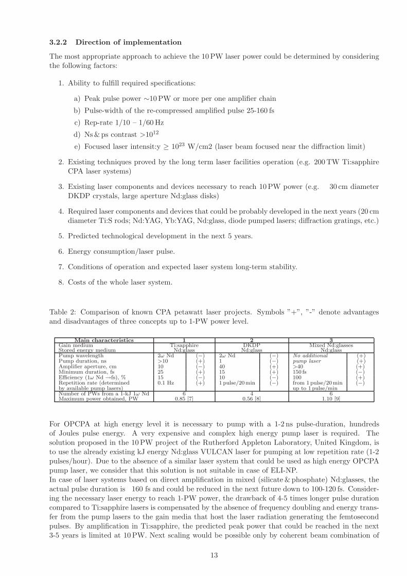
Table 2: Comparison of known CPA petawatt laser projects. Symbols ”+”, ”-” denote advantagesand disadvantages of three concepts up to 1-PW power level.
Main characteristics 1 2 3Gain medium Ti:sapphire DKDP Mixed Nd:glassesStored energy medium Nd:glass Nd:glass Nd:glassPump wavelength 2ω Nd (−) 2ω Nd (−) No additional (+)Pump duration, ns >10 (+) 1 (−) pump laser (+)Amplifier aperture, cm 10 (−) 40 (+) >40 (+)Minimum duration, fs 25 (+) 15 (+) 150 fs (−)Efficiency (1ω Nd →fs), % 15 (−) 10 (−) 100 (+)Repetition rate (determined 0.1 Hz (+) 1 pulse/20min (−) from 1 pulse/20min (−)by available pump lasers) up to 1 pulse/minNumber of PWs from a 1-kJ 1ω Nd 6 4 6Maximum power obtained, PW 0.85 [7] 0.56 [8] 1.10 [9]
For OPCPA at high energy level it is necessary to pump with a 1-2 ns pulse-duration, hundredsof Joules pulse energy. A very expensive and complex high energy pump laser is required. Thesolution proposed in the 10 PW project of the Rutherford Appleton Laboratory, United Kingdom, isto use the already existing kJ energy Nd:glass VULCAN laser for pumping at low repetition rate (1-2pulses/hour). Due to the absence of a similar laser system that could be used as high energy OPCPApump laser, we consider that this solution is not suitable in case of ELI-NP.In case of laser systems based on direct amplification in mixed (silicate & phosphate) Nd:glasses, theactual pulse duration is 160 fs and could be reduced in the next future down to 100-120 fs. Consider-ing the necessary laser energy to reach 1-PW power, the drawback of 4-5 times longer pulse durationcompared to Ti:sapphire lasers is compensated by the absence of frequency doubling and energy trans-fer from the pump lasers to the gain media that host the laser radiation generating the femtosecondpulses. By amplification in Ti:sapphire, the predicted peak power that could be reached in the next3-5 years is limited at 10 PW. Next scaling would be possible only by coherent beam combination of
13

several 10-PW Ti:sapphire femtosecond lasers. Laser systems based on direct amplification in glassesare scalable using the existing technology up to several tens of PW or even to above 100 PW in asingle amplifier arm. Laser amplification in glasses at very high energy (few kJ per pulse) in a singlelaser amplification chain imposes a limitation of the repetition rate (1 pulse every 20-30 minutes)compared to the last amplifier of a 10-PW Ti:sapphire laser that could be pumped by a number of4-8 frequency doubled Nd:glass lasers with an expected repetition rate of 1 pulse/min. Nevertheless,recent achievements in the cooling of high energy Nd:glass disk lasers predict a possible 1 pulse/minuterepetition rate of a 10-PW CPA laser with mixed Nd-doped glasses.For the above mentioned reasons, the following solutions could be considered as suitable for the ELI-NP multi-PW laser:
(1) High energy amplification in Ti:sapphire ( 30 fs pulse duration)
a) Hybrid system that consists in a Front-End based on a Ti:sapphire oscillator and OPCPAin BBO, LBO crystals, followed by high energy amplifiers with Ti:sapphire rods;
b) Front-End based on Ti-sapphire oscillator-amplifiers and high energy amplifiers withTi:sapphire rods
(2) High energy amplification in mixed Nd-doped glasses (100-150 fs pulse duration),as a back-up solution. Hybrid system that consists in a Front-End based on OPCPA in BBO,YCOB crystals, followed by high energy amplification in mixed silicate and phosphate Nd:glassrods and disks.
The basic solution for ELI-NP laser facility consists in an OPCPA Front-End and Ti:Sapphire high-energy amplification stages. A Front-End based exclusively on Ti:sapphire oscillator and amplifiers,with XPW for high intensity contrast, is considered as a back-up solution.An alternative solution is a laser system based on OPCPA Front-End and high energy amplificationin mixed Nd-doped glasses. The existence of an alternative solution is very important for diminishingthe risk of the project.In the following section we describe the solutions proposed for the laser Front-End and the high energyamplifiers chain for the high energy amplification in Ti:sapphire.
3.2.3 Front end
Three types of Front-End configurations could be considered for broadband PW-class CPA lasersystems: All Ti:Sapphire (APOLLON/ LUIRE architecture), ultra-broadband OPCPA with opticalsynchronization (APOLLON/10P architecture), and broadband OPCPA based on BBO crystals withelectronic synchronization (Houston architecture).
All Ti:Sapphire Front EndThe schematic of the Front End (LUIRE configuration) is illustrated in Figure 1 [23]. The systembegins with an ultra-broadband Ti:Sapphire oscillator using dispersive-mirror technology for broad-band intracavity group delay dispersion compensation. The oscillator pulses are stretched to 20-psafter appropriate isolation. After a 10-Hz slicer Pockels cell the pulses are amplified to about 2-mJpulse-energy in a multi-pass Ti:Sa amplifier. Also the spectrum and spectral phase can be pre-shapedby a DAZZLER Acousto-Optic Programmable Dispersive Filter to optimize the amplifier output.After recompression, the laser pulses are injected in a XPW filter in order to improve the temporalcontrast. The filter is based on the generation of a cross polarized wave relative to the incomingone in two BaF2 crystals in between two crossed polarizers [24]. The contrast improvement is givenby the extinction ratio of the pair of high quality polarizers. This filter enables also two othersimportant functions: spatial filtering and pulse duration shortening by a factor of
√3. After XPW
filter the pulses are stretched to nearly 2-ns and then amplified in three multi-pass amplifiers to about200-mJ. To compensate the gain narrowing of the multi-pass amplifiers, a MAZZLER Acousto-OpticProgrammable Gain Control Filter can be used. The Ti:Sa gain media of the multi-pass amplifiers arewater-cooled. The front-end output is coupled to the 1-PW amplifiers chain by a Faraday isolator.
14

The required performances of the 1-PW Front-End output are:• Pulse energy: Eout = 150−200 mJ;• Pulse duration: τout ≈ 2 nsec;• Pulse bandwidth: > 40-nm;• Temporal contrast (ps & ns): ∼ 1012;• Pulse repetition rate: 10-Hz;• Central wavelength: 800-nm;
:Pump lasers:
• PL1: Diode-pumped single longitudinal mode CW laser, 5-W at 532-nm wavelength, 220 VAC,1 KVA apparent power (integrated in the oscillator).
• PL2: Flash-pumped, electrooptically Q-switched Nd:YAG laser, 10-mJ output at 532-nm wave-length and 10-Hz repetition rate, supergaussian smooth spatial profile, 220 VAC, 1 KVA apparentpower.
• PL3: Flash-pumped, electrooptically Q-switched Nd:YAG laser, 100-mJ output at 532-nm wave-length and 10-Hz repetition rate, supergaussian smooth spatial profile, 0.6 KW power consump-tion, 220 VAC, 2 KVA.
• PL4: Flash-pumped, electrooptically Q-switched Nd:YAG laser 1-J / 532-nm, 10-Hz, 4-6 ns,supergaussian smooth spatial profile, 220 VAC, single phase 20 A, 6 KVA, 6 liters/minute at10-40 PSI pressure drop.
Figure 1: Schematic overview of the 1-PW front-end [23]
Table 3: Front End requirements
Apparent power 11 KVA, 1 phase, 220 VAC
Power consumption 8 KW
Cooled Water 8 liters / min, 12 C degree
Clean room class At least 50 000
Relative humidity 30 – 50 %
Clean room dimensions 5 x 6 m2
15

Ultra-broadband OPCPA Front End
The goal of this configuration is very demanding: to provide energetic ultra-broadband laser pulsesfor Ti:Sa power-amplifiers chain. The main characteristics of the output pulse are: 800-nm centralwavelength. 100-mJ energy, > 70-nm spectral bandwidth (that means after compression < 10-fs fullwidth at half-maximum duration for a squared hyperbolic secant temporal shape), 10-Hz repetitionrate.The schematic of the OPCPA Front End includes an 800-nm CPA signal chain and an 1030-nm CPApump chain, as shown in Figure 2. The 800-nm chain begins with a commercial ultrashort Ti:Sapphireoscillator-amplifier system (25-fs pulse width, 2-mJ pulse-energy, > 30-nm bandwidth at 800-nmcentral wavelength and 1 kHz repetition rate). The output of the Ti:Sa amplifier is spectrally enlargedin an argon-filled hollow-fiber to obtain ultra-broadband laser pulses of less than 10-fs duration. Thenthe pulses are injected in a XPW filter in order to improve the temporal contrast. After XPW filterthe pulse is back-reflection isolated and is chirped in a stretcher to 10 ps. The chirped pulse is thenamplified in two ultra-broadband non-collinear OPCPA stages (NOPCPA) that use BBO or LBOnonlinear crystals. The NOPCPA stages are pumped with 515-nm nanosecond pulses provided by apart of the frequency-doubled pump chain output. This pico second OPCPA process is mandatory topreserve at the same time high gain and broadbandwith.It is critically important for efficient and stable operation of the OPCPA stages to accurately syn-chronize pump and signal pulses. An all-optical synchronization technique [26, 27] is used in thisconfiguration. The pump and signal chains are injected with the same seed provided by the Ti:Saoscillator and exact synchronization can be maintained during the pump pulses are boosted to highenergies.A very weak narrowband signal of 1030-nm extracted from the broadband output pulse of the Ti:Saoscillator is used as a pump-seed. The energy of the seed pulse is further increased in an ytterbiumdoped fiber amplifier. The amplified seed is chirped and then is injected into a diode-pumped regener-ative amplifier based on potassium gadolinium tungstate crystals doped with ytterbium (Yb:KGW).The output of the regenerative amplifier (2 mJ, 700 ps, 1 kHz, 1030 nm) is injected into a chain ofdiode-pumped multipass amplifiers based on different ytterbium- doped crystals (KGW, CaF2, YAG)to reach after recompression and Frequency doubling, 100mJ unchirped energy. This picosecond pumpis used to amplifiy the signal through an OPCPA preamplifier to 10-20mJ. A 20mJ remaining partof the pump beam will be then stretched again to ns pulse duration then amplified to finally infraredpulses of 2 J energy, 2 ns duration, possibly at 100 Hz repetition rate at 1030 nm wavelength.After frequency doubling in nonlinear crystals the high-energy output (1 J pulse energy, 1.8 ns duration,0.9 nm bandwidth, 10 Hz repetition rate, 515 nm wavelength) is used to pump the final NOPCPAamplifier stage. The signal exiting the picosecond OPCPA preamplifier is then stretched again to1ns. The losses induced in the secondary stretcher (30% throughput) will be compensated in this finalNOPCPA stage. The largest issue will be to combine the chirp of the signal and the chirp of thepump beam to preserve the final compressibility of the PW pulse. The output of the first NOPCPAprovides ultra-broadband pulses of 15-mJ energy, <70-nm bandwidth, 800-nm central wavelength at100-Hz rate, that are further amplified in the final NOPCPA. During amplification, the repetition rateof the pump pulses is gradually reduced from 1-KHz at the regenerative amplifier to 10-Hz at the finalNOPCPA stage.
An active control of the spectral phase by using DAZZLER dispersive filters will be necessary forboth signal and pump pulses.
OPCPA critical design issues• Very precise time/space synchronization of signal and pump pulses;• High-intensity/ high-stability and high quality pump beams (not currently available);
OPCPA key features:• High signal gain (>1000 in a single pass crystal);
16

Figure 2: Schematic overview of the 1-PW front-end [23] YDFA, ytterbium doped fiber amplifier ;MP1-MP4, multipass amplifiers based on ytterbium- doped crystals (KGW, CaF 2, YAG); XPW, cross-polarized wave generation filter. NOPCPA, non-collinear optical parametric chirped pulse amplifiers
• Broad bandwidth (ultrashort re-compressed pulses);• Negligible thermal loading;• High signal - noise contrast ratio;• High energy pulses in available large non-linear crystals, no transversal lasing;
Table 4: OPCPA Front End requirements
Apparent power 9 KVA, 1 phase, 220 VAC
Power consumption 7 KW
Cooled Water 6 liters / min, 12 C degree
Clean room class At least 50 000
Relative humidity 30 – 50 %
Clean room dimensions 5.5 x 10.5 m2
Nanosecond OPCPA Front EndAn alternative solution is a simple electronically synchronized OPCPA Front-End. Seed pulses gen-erated by a Ti:sapphire oscillator (∼800 nm central wavelength) are stretched up to ns duration andare amplified in BBO crystals pumped by nanosecond laser pulses given by Nd:YAG lasers [9] up tofew millijoule level. The majority of the system gain is achieved in 2-4 OPCPA stages, which usenon-collinear optimized OPA geometries. A good intensity contrast of the amplified pulses is pre-served. Unlike the OPCPA based on optical synchronization with BBO crystals seeded by spectrallybroadened input pulses and pumped by picosecond pulses, the available gain bandwidth in this caseis broad-enough to amplify pulses re-compressible down to 25-30 fs, similar with the pulse durationobtained in Ti:sapphire amplifier systems.
17

3.2.4 High rep rate PW amplifiers
The stage of amplification consists of two multi-pass Ti:Sa amplifiers: a pre-amplifier and a poweramplifier. The amplifiers chain has a gain of 120-140 to yield an output pulse-energy exceeding 30 J(Figure 3). The Front End pulses are spatially filtered and magnified to an appropriate diameter, andthen are seeded into the preamplifier. After backreflection isolation, the 3-5 J output pulses of thepreamplifier are again spatially filtered and magnified and then are injected into the power amplifier.The fluence of the laser beam is maintained down to 1.5 J/cm2 and the local peaks should be below2 J/cm2 in the amplifier chain.The preamplifier is pumped by two laser beams of 8 J pulse energy provided by four nanosecondNd:YAG lasers of 4 J pulse-energy at 532 nm wavelength and 10 Hz repetition-rate. Two high-energynanosecond Nd:Glass lasers of 50 J pulse-energy at 527 nm and 0.1-0.05 Hz repetition-rate are used topump the power amplifier.The required performances of the 1-PW Amplifiers Chain output are:
• Pulse energy: Eout > 30 J;• Pulse duration; τ out ≈ 2 nsec;• Re-compressible down to 20 fs;• Pulse repetition rate: 0.1-0.05 Hz;• Central wavelength: 800 nm;
Figure 3: Schematic overview of the 1−Petawatt laser chain
Critical design issues of the Amplifiers ChainAs it is well known in femtosecond laser technology, the quality of the pump beams is a key parameterto achieve good beam quality of the amplified pulses and high efficiency. Two main factors are criticalfor the green pump beams:• Smooth spatial profile with no hot spots, to generate gain in homogeneity, a very important parame-ter in multipass power amplifiers. Combining the beam homogenization technique based on diffractiveoptical elements with the double pass pumping technique, a high-quality optical pumping could beobtained if managing carefully the coherence properties of the pump laser itself. A compromise mustbe chosen between high spatial coherence leading to high SHG conversion efficiency but 100% energymodulations (fringes) on the pump crystal, and low spatial coherence necessary for efficient smoothingbut reducing drastically the SHG efficiency. To overcome this difficulty and obtain efficient beamsmoothing and high SHG sophisticated longitudinal mode beating must be implemented in the pumposcillator to suppress the temporal coherence [28].• Low beam-quality parameter M2 for easy focusing and long Rayleigh length to achieve a good overlapof pump and infrared beams in Ti:Sa crystals. As the pump repetition rate increases, the thermaloptical power of the gain media increases proportionally and the pump waist must be reduced tomaintain the gain at a high value and this is making the M2 issue more critical.
18

• Ti:Sa cooling technique and the crystal mount design have to minimize the thermal effects inducedin gain media and the transverse lasing, in order to preserve a high gain with a Strehl ratio near thediffraction limit. Cryogenically cooling of the preamplifier Ti:sapphire rod at 10 Hz repetition rate isconsidered.• Accurate time positioning of the gain buildup curve could prevent the transverse lasing and alsoreduces ASE. This technique is based on the fine synchronization of the different pump lasers on theamplifiers chain. This technique could be efficient to reduced transverse parasitic lasing, but it must becombined with more efficient strategies consisting in careful management of the absorption coefficientof the TiSa crystal, and even more efficient, the management of the optical reflective (or scattering)properties of the crystal perimeter surfaces. Moreover for large pumping areas, the transverse ASEgain could be high enough to deplete the population inversion and reduce the amplification efficiencywithout any need of transverse oscillations. Transverse ASE management is one of the largest issuesat that level of amplification.• Alternative solution of power supplies with closed loop water cooling and chillers instead of cooledwater are considered. In this case the necessary water flow rate will be drastically diminished.
Table 5: The requirements for 1−PW Amplifier Chain
Apparent power 100 KVA, 1 phase, 220 VAC, 50 Hz, 20x25 A plugs
Power consumption 80 KW
Cooled Water 100 liters / min, 12-17 C degree
Clean room class At least 50 000
Relative humidity 30 – 50 %
Clean room dimensions 12 x 6 m2 (including the Front End)
3.2.5 High energy amplifiers
The output of the 1-PW system is injected in a high-energy amplifiers chain in order to finally increasethe pulse energy to about 300 J while keeping the bandwidth broad enough for 15-30 fs pulses. The10-PW chain consists of two multi-pass high-energy Ti:Sa amplifiers: 80-J amplifier stage and the300-J final amplifier stage operating at a repetition rate of 1 pulse per minute.These high-performance parameters require an important technological effort to develop a new genera-tion of laser components (laser mirrors, Ti:Sa crystals, pump lasers) with improved features regardingthe size, optical quality, damage-threshold, pump-beam quality and pulse-energy.Critical design issues of the 10-PW Chain
• High-quality Ti:Sapphire crystals of large sizes: 100-mm diameter and 170-mm diameter [23];• Large-size laser mirrors ( 300 mm diameter) having a high reflectivity in a bandwidth of 200-nmaround the 800-nm central wavelength and also the control of group velocity dispersion (GVD) at 2.5J/cm2 working energy density [23];• Laser mirrors with variable spectral reflectivity for each amplifier input in order to minimize thegain-narrowing effect in the Ti:Sa amplifiers [23];• 100-400 J green pump-beams with homogenized smooth spatial profile without hot spots and lowbeam-quality parameter M2 for easy focusing and long Rayleigh length to achieve a good overlap ofpump and infrared beams in Ti:Sa crystals;• Ti:Sa cooling technique and the crystal mount design in order to minimize the thermal effects inducedin gain media;• Accurate time positioning of the gain buildup curve to prevent the transverse lasing and also reducesASE. This technique involves a fine synchronization of the different pump lasers on the amplifiers chain.• Alternative solution of power supplies with closed loop water cooling and chillers instead of cooledwater are considered. In this case the necessary water flow rate will be drastically diminished.
19

Table 6: The requiremens for 10−PW Amplifier Chain
Apparent power 130 KVA, 1 phase, 220 VAC, 50 Hz, 30x25 A plugs
Power consumption 100 KW
Cooled Water 100 liters / min, 12-17 C degree
Clean room class At least 50 000
Relative humidity 30 – 50 %
Clean room dimensions 10 x 5 m2
3.2.6 ELI-NP multi-PW laser system conceptual design
The schematic drawing is shown in the figure 4. The design ofthe facility is modular, reserving the space for further extension of the laser system and allowing theextension of the experimental area later in time, according to the needs.
Figure 4: ELI-NP scheme. FE1, FE2 - Font-End based on OPCPA or Ti:sapphire amplification.A1-A5 - Ti:sapphire amplifiers.
The ELI-NP laser facility will use OPCPA technology at the front-end and Ti:Sapphire high-energyamplification stages, similar to the ones developed at the Apollon-type laser system described in thesection 3.2. A front-end based exclusively on Ti:sapphire oscillator and amplifiers, with XPW forhigh intensity contrast, is considered as a back-up solution. The ELI-NP laser facility will have twofront-ends. They will temporally stretch and amplify initial ultrashort pulses with 800 nm centralwavelength to the 30 mJ level, preserving the needed large bandwidth of the 15 fs laser pulses andthe temporal contrast of the pulses in the range of 10−12. Due to the complexity of such OPCPAsystem, the alignment and maintenance time for one front-end is long. To avoid such dead-times, onefront-end is planned to operate at a time, the second one being used during the maintenance of the
20

other front-end, significantly increasing the available beam-time of the laser facility.The pulses of 2 ns at 10 Hz repetition rate generated by the front end are amplified by A1 up to600 mJ, splitted and distributed to further A2 laser amplifiers. A1 is pumped by a 2J green (532 nm)nanosecond Nd:YAG laser. After A2 laser pulses are amplified to 3.5 J at 10 Hz repetition rate. A2 ispumped by 4 X 4 J green lasers. The Ti:sappire rod of the A2 amplifier will be cryogenically cooledfor 10 Hz operation. Using a flipper mirror these pulses can be sent to a temporal compressor and,after compression down to 25 fs, to a 100 TW reaction chamber. 35 J pulses at 0.1 Hz repetition rateare generated after amplifier A3, pumped by 4 x 25 J Nd:glass lasers. A secondary output is dedicatedto experiments at 1PW power level. At these energy levels, the laser pulses can be extracted from thelaser amplification chain and recompressed to less than 25 fs pulse duration in a vacuum compressor.Subsequently, they are distributed to the 1 PW experiments room.Alternatively, the laser pulses are further amplified in the amplification chain to energies of the orderof 300 J in the last two power amplifiers A4 and A5 with a repetition rate of at least 1 pulse/min. A4,pumped by four high energy lasers ( 50 J/pulse at 35 ns pulse duration), raises the pulse energy up to80 J with a repetition rate of 0.05 Hz. The last amplifier is pumped by 8 x 100 J green lasers coupledin 4 pairs of 200 J pump energy each. The output beam diameter of 180 mm is expanded to 400 mmbefore the 10-PW temporal compressor input. Adaptive optics and optical isolation of the pulses willbe implemented before the optical compressor.The ultrashort pulses will be distributed to the high energy experimental areas, where stand-aloneexperiments or combined nuclear physics experiments using the highly brilliant γ beam will be per-formed.Coherent combination of the high power ultrashort pulses from the parallel amplification chains isenvisaged, in order to reach intensities of the order of 1023 W cm−2 and above. The operation of theexperiments will take place in parallel, the laser pulses being delivered to different experimental areason request.
3.2.7 ELI-NP laser building sketch
The two arms of 10 PW ELI-NP laser system are placed in an area of approximate 42 x 34 m2 (figures 5and 6). A 50 x 50 m2 area would be available for further extensions of the laser system and experimentalrooms. The laser system is installed in a 10.000 class clean room (50.000 class could be consideredas a minimum requirement), thermally stabilized within ± 0.5 K, and controlled humidity of 30-50%.The actual area of the laser clean room is about 820 m2 with at least 3m height.Working conditions and radioprotection measures in each experimental room will be defined depend-ing on proposed experiments. Big area experimental rooms allow a variable configuration of radio-protection walls.
Ti:sapphire laser components and pump green laser heads are arranged inside the clean room on anetwork of rigid joint optical tables of 90 cm height from the floor, with 30 cm thickness of the tables.The level of optical axes of laser beams is about 150 mm up from the surface of optical tables in theFront-End, A1, and A2 amplifiers and 250 mm in the A3-A5 amplifiers. Optical axes of input laserbeams for 100 TW, 1 PW, and 10 PW vacuum compressors are raised up to 1.5 m from the floor byperiscopes.All power supplies are placed in a technical room of approximate 110 m2 area and 3.5 m height. Incase of pump lasers with closed loop liquid cooling, all chillers will be installed out of the building.There are two experimental rooms for each laser arm, where femtosecond laser beams of 100 TW at10 Hz and 1PW at ≥ 0.1 Hz repetition rate are available for different laser-matter interactions.If weconsider a laser system running at 10 Hz up to 100 TW power and at maximum 1Hz up to 10 PW,theestimated electrical power consumption will be 2×200 kW = 400 kW for the whole laser system. Thenecessary of cooling water flow rate depends on the technical solution chosen by the producers forpump lasers and could be estimated as maximum 2×200 l/min = 400 l/min in case that all pumplasers will be cooled by running water (no closed loop chillers).
21
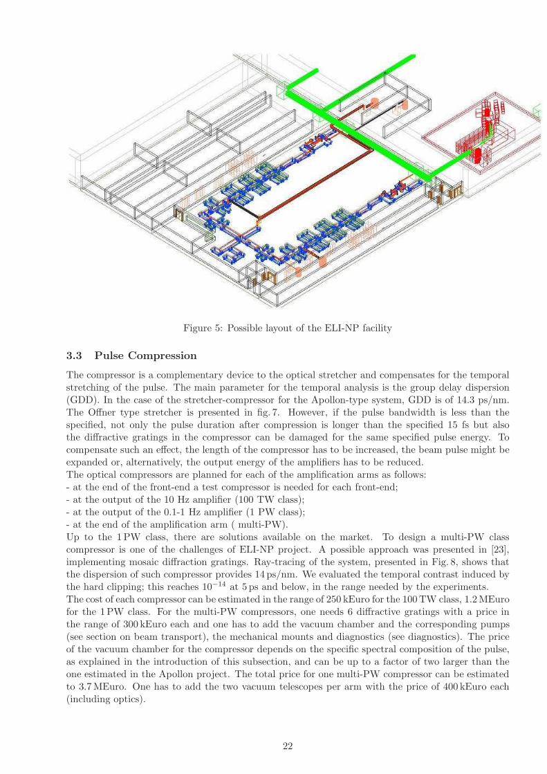
Figure 5: Possible layout of the ELI-NP facility
3.3 Pulse Compression
The compressor is a complementary device to the optical stretcher and compensates for the temporalstretching of the pulse. The main parameter for the temporal analysis is the group delay dispersion(GDD). In the case of the stretcher-compressor for the Apollon-type system, GDD is of 14.3 ps/nm.The Offner type stretcher is presented in fig. 7. However, if the pulse bandwidth is less than thespecified, not only the pulse duration after compression is longer than the specified 15 fs but alsothe diffractive gratings in the compressor can be damaged for the same specified pulse energy. Tocompensate such an effect, the length of the compressor has to be increased, the beam pulse might beexpanded or, alternatively, the output energy of the amplifiers has to be reduced.The optical compressors are planned for each of the amplification arms as follows:- at the end of the front-end a test compressor is needed for each front-end;- at the output of the 10 Hz amplifier (100 TW class);- at the output of the 0.1-1 Hz amplifier (1 PW class);- at the end of the amplification arm ( multi-PW).Up to the 1 PW class, there are solutions available on the market. To design a multi-PW classcompressor is one of the challenges of ELI-NP project. A possible approach was presented in [23],implementing mosaic diffraction gratings. Ray-tracing of the system, presented in Fig. 8, shows thatthe dispersion of such compressor provides 14 ps/nm. We evaluated the temporal contrast induced bythe hard clipping; this reaches 10−14 at 5 ps and below, in the range needed by the experiments.The cost of each compressor can be estimated in the range of 250 kEuro for the 100 TW class, 1.2 MEurofor the 1PW class. For the multi-PW compressors, one needs 6 diffractive gratings with a price inthe range of 300 kEuro each and one has to add the vacuum chamber and the corresponding pumps(see section on beam transport), the mechanical mounts and diagnostics (see diagnostics). The priceof the vacuum chamber for the compressor depends on the specific spectral composition of the pulse,as explained in the introduction of this subsection, and can be up to a factor of two larger than theone estimated in the Apollon project. The total price for one multi-PW compressor can be estimatedto 3.7 MEuro. One has to add the two vacuum telescopes per arm with the price of 400 kEuro each(including optics).
22

Figure 6: Detail of figure 5: Amplification arm layout with compresor position and beams to experi-mental areas
Figure 7: Possible Offner-type stretcher design for the front-end
3.4 Alignment and Diagnostics
For the laser diagnotics and alignment, we have envisaged a list of necessary equipments for thedifferent laser parts:1) after the fs oscillator: beam splitter, energy meter, CCD camera, quadrant photodiode detectorand motorized iris diaphragm;2) after the booster and strecher: beam splitter, energy meter, CCD camera, quadrant photodiodedetector, fast photodiode, oscilloscope;3) before the regenerative amplifier: beam splitter, energy meter, CCD camera, fast photodiode,oscilloscope;4) before the multi-pass amplifier: beam splitter, energy meter, CCD camera, fast photodiode, quad-
23

rant photodiode detector;5) at the front-end output: beam splitter, energy meter, CCD camera, fast photodiode, quadrantphotodiode detector, compressor stage for test;6) after the A1 and A2 amplifiersbeam splitter, energy meter, CCD camera, fast photodiode, quadrantphotodiode detector, motorized iris diaphragm, beam cleaning equipment;7) after A3, A4 and A5 power amplifiers: beam splitter, energy meter, CCD camera, fast photodiode,quadrant photodiode detector, motorized iris diaphragm, beam cleaning equipment;8) after the compressor: beam splitter, energy meter, CCD camera, SPIDER, autocorrelator 3rd order.
3.5 Pulse shaping
There are several methods to shape the pulse: namely spatial, temporal, spectral and phase shaping.For the spatial shaping, adaptive mirror is planned after the A2 amplifier and possibly after the finalamplifier. The cost for adaptive mirror and sensor are 300 keuro for two arms.Temporal and spectral shaping are complementary approaches in the sense that the pulse duration andspectral composition of the pulse are in a Fourier transform relation. Most of the shaping techniquesrefer to the spectral and phase shaping. One can use acusto-optic modulators for phase and amplitude,liquid crystals for 4f shaper or, in the case of OPCPA technique, spectral modulation by pump laserintensity modulation. At this moment it is unclear which of the technologies will be used.
3.6 Control, supervision system (C2S)
The monitoring and control systems study comprehends the necessities and the particularities in-volved by the complexity and dimensions of ELI-NP project, and the actual technological capabilities(including commercial equipment software and service).Regarding the ELI-NP project requirements, we identify three major types of control and monitoringsystems, as presented in fig. 9:
1. Basis control system;1. Automation;1. System and ambient monitoring and data logging;
1. Basis control system- include all control systems which assure laser synchronization devices, interlocks, optical path control,beam combination and shaping, control and command of auxiliary devices (pumping laser, vacuum
Figure 8: Possible configuration for the compressor
24
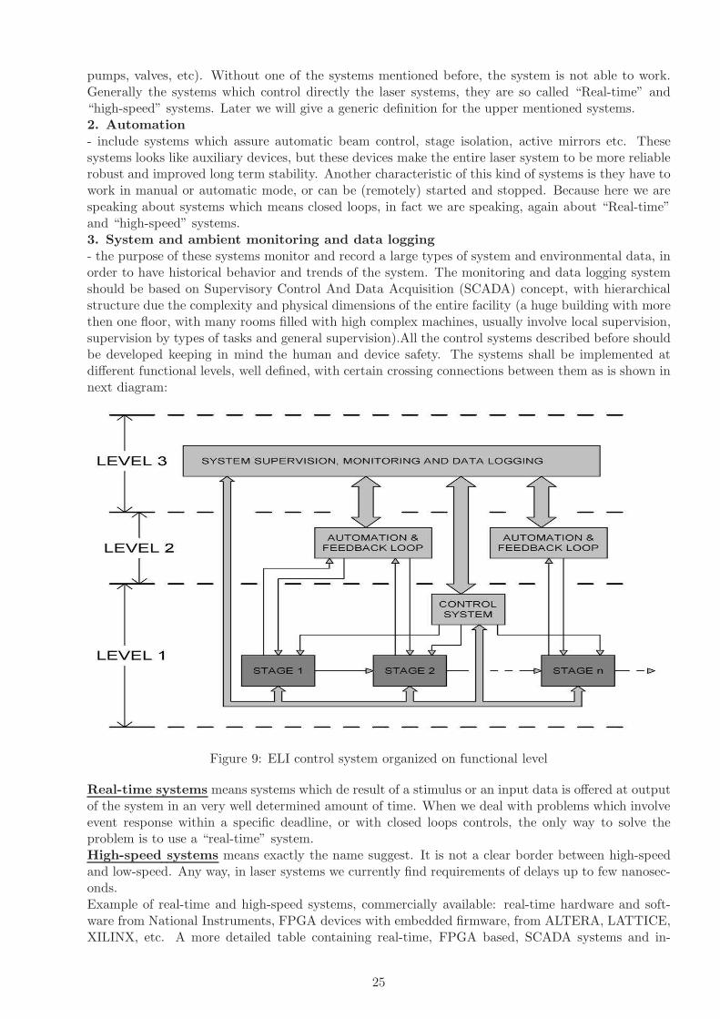
pumps, valves, etc). Without one of the systems mentioned before, the system is not able to work.Generally the systems which control directly the laser systems, they are so called “Real-time” and“high-speed” systems. Later we will give a generic definition for the upper mentioned systems.2. Automation- include systems which assure automatic beam control, stage isolation, active mirrors etc. Thesesystems looks like auxiliary devices, but these devices make the entire laser system to be more reliablerobust and improved long term stability. Another characteristic of this kind of systems is they have towork in manual or automatic mode, or can be (remotely) started and stopped. Because here we arespeaking about systems which means closed loops, in fact we are speaking, again about “Real-time”and “high-speed” systems.3. System and ambient monitoring and data logging- the purpose of these systems monitor and record a large types of system and environmental data, inorder to have historical behavior and trends of the system. The monitoring and data logging systemshould be based on Supervisory Control And Data Acquisition (SCADA) concept, with hierarchicalstructure due the complexity and physical dimensions of the entire facility (a huge building with morethen one floor, with many rooms filled with high complex machines, usually involve local supervision,supervision by types of tasks and general supervision).All the control systems described before shouldbe developed keeping in mind the human and device safety. The systems shall be implemented atdifferent functional levels, well defined, with certain crossing connections between them as is shown innext diagram:
Figure 9: ELI control system organized on functional level
Real-time systems means systems which de result of a stimulus or an input data is offered at outputof the system in an very well determined amount of time. When we deal with problems which involveevent response within a specific deadline, or with closed loops controls, the only way to solve theproblem is to use a “real-time” system.High-speed systems means exactly the name suggest. It is not a clear border between high-speedand low-speed. Any way, in laser systems we currently find requirements of delays up to few nanosec-onds.Example of real-time and high-speed systems, commercially available: real-time hardware and soft-ware from National Instruments, FPGA devices with embedded firmware, from ALTERA, LATTICE,XILINX, etc. A more detailed table containing real-time, FPGA based, SCADA systems and in-
25

dustrial communication protocols will be soon available. Another useful observation is this complexproject will contain commercially available laser systems combined with systems in situ developed.Control system team should develop in situ laser control systems, among to integrate the commerciallysystems (acquired during the entire project development) into a general shell.
The next table describes first version of Control-Command (C2) & Supervision system (C2S) forELI laser system.
Table 7: Control-command (C2) & supervision system (C2S)
Functions Equipments to control Environmental Safetyand command specs & Remarks
C2S:-provides laser safety and security forthe PSS (Personnel Safety System)-governs the operating and sequen-tial modes of the machine-integrates a general view of themachine (supervision, system states,troubles, alarms)-manages the configuration of themachine equipments-manages the generated results anddata
-security elements: door contacts,interlocks, shutters, obstructers,valves-HV supplies-lasers-oscilloscopes-multi-ways digital measuring ap-paratus-delay generators-energy-meters-spectrometers- CCD cameras-motors (mirror mounts, spatialfilter sets, diffraction gratings,translation and rotation stages, fil-ter gratings, plate holders, targetholders, holders for frequency con-version crystals)-valves, pumps, gauges-ambient sensors (temperature,humidity, dust)
• indoor use• T = (0-55) 0C,• h = (10-90)%,non-condensing• EMC:-emissions =EN 55011 Class A at 10 m-immunity =EN 61326:1997 + A2:2001• Vin = 230 V• fin = 50 Hz• Iin = 8 A
• laser• HV• X-rays-C2S requirementsare generated bythe experimenters orexperimental resultsand are destinedfor the other biginstallations
C2:-operates the distribution of the laserbeams from the pilot to the target-configures and operates the pump-ing lasers-adjusts the synchronization systems-operates the alignment and laser di-agnosis systems-operates the vacuum systems
-C2 requirementsare generated bythe laser moduledevelopers / users
3.7 Coherent beam combining
Coherent beam combining (CBC) of multiple ultra-short laser beams represents an effective solution toobtain a high power laser for both continuous wave and pulsed systems. Methods for coherent beamcombining have not been very successfully applied, although many different approaches have beeninvestigated. CBC method has been demonstrated with diode, solid-state, fiber, and gas lasers, butcurrent efforts focus on fiber lasers and diode in continuous regime. Up to now, little work is relatedto pulsed lasers in the ns range and below. However, in order to scale the intensities of ultra-shortpulse lasers in the femtosecond domain such CBC technique is needed.Coherent beam combining technique requires that the sources are coherent and relative phases ofcombined beams are precisely controlled to a small fraction of the wavelength. The main difficultyis to obtain phase coherence at high power levels in a sufficiently stable manner, working not onlyin a quiet laboratory environment but also in a mechanically more noisy industrial setting. Anotherchallenge is the need to match precisely and stably wavefronts and polarization directions.One way to coherently combine the ultrashort pulses is to take several identical ultrashort pulsesand overlap them directly on the target. Up to now no experimental report exists concerning thisapproach. However, if this works, there might be an alternative better solution that would allow toobtain significantly increased power on the target, by using laser pulses with complementing spectralcomposition.
26

One important issue in CBC relates to the mechanical stability of the entire laser amplification chainand to the possibility to measure and control the specific displacements. This might increase the costof the mechanical components along the amplification path a factor of 2 or 3. Related interferomet-ric methods for optical path stabilization are currently developed in INFLPR, within LASERLAB2European project.
3.8 Laser Beam Transport System
In order to produce petawatt laser beams, a large section of the the ELI facility will be under vacuum.A system which will comprise a large chamber (compressor) which will host optical components anda long pipe for beam transport will be pumped down by a number of forevacuum and turbomolecularpumps. Alternatively, diffusion or cryopumps could be used for rapid air evacuation inside the largestvolumes, down to 10−6 torr.COMPRESSOR CHAMBERRealization of energy amplification will be possible only by using an array of gratings for beam com-pression which will be achieved in the compressor chamber. The chamber will have a volume of 15 m3
(5 m × 1.5 m × 2 m) if the pulse contains enough bandwidth. The thickness of the chamber wallsdepend on the materials used, whether it will be aluminum or stainless steel. In principle, aluminumwill be the preferred material for weight considerations. Different solutions are currently analyzed forthe design of the chamber. The chamber will be provided with several large windows and ports whichwill allow access to the optical components hosted inside. Two large grating with diameters of up to90 cm installed on precision mounts will be the main parts of the compressor.PIPES FOR BEAM TRANSPORTThere will be 3 vacuum systems which will deliver 3 beams to one main target chamber and withthe possibility to divert 2 beams to two separate smaller target chambers. Each system will have acompressor and a long pipe with a length of 15 m, which will include elbows to transport the beambetween adjacent floors of the building. While the exact aperture of the beam has not been calculated,from the experience of other petawatt facilities it is expected that the diameter of the pipes used totransport the high-power beam (up to 10 Petawatt) will be 1 m. The thickness of the pipe wall, if Alis considered, will be about 15 mm. Sections with a length of 1.5 m will be bolted together creating a15 m long pipe.A major company (AtlasUHV), supplier of large-scale vacuum systems for experiments at NIF, Ar-gonne, Los Alamos, CERN has been queried about the price evaluation of the chamber and the pipingsystem. A first estimate indicates an initial price in the range of 200-300 k$ for the vacuum systemalone corresponding to one beam, excluding site installation.
3.9 Further infrastructure
Supporting labs and mechanical workshops has to be organized at the ELI facility. These will be fullyequipped for satisfying the demands for operation and maintenance of the equipments, preparationand running of the experiments.1. Optical workshops are required for inspection, cleaning or treatment of various optical compo-nents such as gratings, mirrors, laser crystals, etc. The workshop has to be divided in tree separateworking areas providing specific working conditions for inspection of the optical components, respec-tively for their treatment or cleaning.
Inspection area:Equipments:1 metallographic microscope (Transmission & Reflection), 2 inspection microscopes, 1 optical spec-trometer for transmission & reflection characterization, 1 spectro-ellipsometer (this layer inspection),1 profilometer, interferometers.Utilities: Clean room conditions Class 10.000, dry nitrogen.Surface: 60 m2
Cleaning area:
27

Equipments:Utilities: Clean room conditions Class 1.000, dry nitrogen.Surface: 30 m2
Treatment area:Equipments:2 lapping machines, 2 ultrasonic bath 0.5 l, 1 ultrasonic bath 10 l, 2 vacuum pumpsUtilities: compressed air, dry nitrogen, tap water, laminar air flow cabinet, air exhaust system.Surface: 50 m2
2. Target microfabrication workshop. Here the targets for experiments are produced. Thedesigned targets could have different sizes and forms on different materials. Micromachining tools andsample preparation tools are used.Equipments: diamond cutting machine, laser cutting system, laser micro-stereo-lithography system,analytical balance, optical microscopes, spin-coater, coordinate-measuring machine.Utilities: compressed air, dry nitrogen, tap water, laminar air flow cabinet, air exhaust system.Surface: 90 m2
3. Chemical workshop is used for sample preparation. It has to be a different room to the Targetmicrofabrication Room, providing the necessary conditions for safely working in chemical area. Thechemical workshop has to be placed close to the Target microfabrication room.
Equipments: 2 fume hoods, centrifuges, ph meters, analytical balance, oven, vacuum pumps, chemicalglasses and small chemistry laboratory equipment.Utilities: compressed air, tap water, air exhaust system, chemically resistant benches.Surface: 40 m2
4. Electrical workshop is need for maintenance or testing of various electronic equipments, smallequipments or electronic subsystems of the laser power supply, detectors, and control and acquisitionsystems. Here will be also assembled the electronic parts of the automations systems for the runningexperiments.Equipments: 1GHz Oscilloscope (or better), 4 service oscilloscope (4 channel each), 2 function gen-erator, 1 LCR bridge, 1 spectral analyzer, 1 network analyzer (1 line), 3 laboratory power supply, 2galvanic separators (500 VA or better), 1 bench digital multimeters, 2 portable digital multimeter, 4computers, soldering machines (iron and hot air flow), bench drilling machine, small electrical tools.Surface: 90 m2
Utilities: compressed air, fume extraction system, tap water, 3-Phase line.
5. Mechanical workshop has to be equipped with necessary machining tools for processing me-chanical parts used in experiments.Equipments: 1 professional CNC milling machines, 1 CNC metalworking, 2 small milling machines, 2small metalworking lathe, 1 bench drilling machines, band saw, hydraulic press, electric hand tools.Utilities: compressed air, tap water, 3-Phase line.Surface: 100 m2
28

References
[1] D. Strickland and G. Mourou, Opt. Commun. 56, 219 (1985).
[2] M. D. Perry and G. Mourou, Science 264, 917 (1994).
[3] D. M. Pennington, M. D. Perry, B. C. Stuart, et al., in Proceedings of the Solid State Lasers forApplication to Inertial Confinement Fusion: Second Annual International Conference, London,1997, Proc. SPIE 3047, 490–500 (1997).
[4] M. D. Perry et al., Opt. Lett. 24, 160 (1999).
[5] Y. Kitagawa, H. Fujita, R. Kodama, et al., IEEE J. Quantum Electron. 40, 281 (2004).
[6] C. N. Danson, P. A. Brummitt, R. J. Clarke, et al., Nucl. Fusion 44, S239 (2004).
[7] M. Aoyama, K. Yamakawa, Y. Akahane, et al., Opt. Lett. 28, 1594 (2003).
[8] V. V. Lozhkarev, G. I. Freidman, V. N. Ginzburg, et al., Laser Phys. Lett. 4, 421 (2007).
[9] E. W. Gaul et al., Appl. Opt. 49, 1676-1681 (2010).
[10] I. N. Ross, P. Matousek, G. H. C. New, and K. Osvay, J. Opt. Soc. Am. B 19, 2945 (2002).
[11] R. Li, Y. Leng, and Z. Xu, in Proceedings of the Conference on Lasers and Electro-Optics, 2005,p. CMB1.
[12] J. Hein, S. Podleska, M. Siebold, et al., Appl. Phys. B 79, 419 (2004).
[13] C. P. J. Barty, M. Key, J. A. Britten, et al., in Proceedings of the Conference on Lasers andElectro-Optics, OSA Trends in Optics and Photonics, San Francisco, CA, 2004 (Optical Societyof America, Washington, 2004), p. JTuG4.
[14] L. J. Waxer, D. N. Maywar, J. H. Kelly, et al., Opt. Photonics News 16, 30 (2005).
[15] E. W. Gaul, T. Ditmire, M. D. Martinez, et al., in Proceedings of the Conference on Lasers andElectro- Optics, Baltimore, 2005, p. JFB2.
[16] N. Blanchot, E. Bignon, H. Coic, et al., in Proceedings of the Topical Problems of Nonlinear WavePhysics, 2005, Proc. SPIE 5975, 0C1-0C16 (2005).
[17] J. L. Collier, O. Chekhlov, R. J. Clarke, et al., in Proceedings of the Conference on Lasers andElectro Optics, Baltimore, 2005, p. JFB1.
[18] V. V. Lozhkarev, S. G. Garanin, R. R. Gerke, et al., JETP Lett. 82, 178 (2005).
[19] V. Yanovsky et al., Opt. Express, 16, 2109-2114 (2008).
[20] S. K. Lee et al., 0.1-Hz 1-PW Ti:Sapphire Laser facility, LEI Conference, Brasov, Romania,October 16-21, 2009.
[21] Z. Wang et al., Enhance XL III facility to Petawatt power with improved front-stage amplifierand optimized output energy, LEI Conference, Brasov, Romania, October 16-21, 2009
[22] J. P. Chambaret, The Extreme Light Infrastructure Project ELI and its prototype APOLLON/ILE. “The associated laser bottlenecks”, LEI Conference, Brasov, Romania, October 16-21, 2009.
[23] Projet CPER 2007-2013 APOLLON ILE 10-PW, 2009.
[24] A. Jullien et al., Opt. Express, vol. 14, pp. 2760–2769 (2006); A. Jullien et al., Appl. Phys. B,vol. 84, pp. 409–414 (2006); L. Canova et al., Appl. Phys. Lett., vol. 92, pp. 231102 1-3 (2008).
29
[25] I. N. Ross, J. L. Collier, P. Matousek, C. N. Danson, D. Neely, R. M.Allott, D. A. Pepler, C.Hernandez-Gomez, and K. Osvay, Appl. Opt.39, 2422-3427 (2000).
[26] Y. X. Leng, X. D. Yang, H. H. Lu, L. H. Lin, Z. Q. Zhang, R. X. Li, ,D. J. Yin, and Z. Z. Xu,Opt. Eng. 43, 2994–2997(2004).
[27] Y. Leng, L. Lin, X. Yang, H. Lu, Z. Zhang, and Z. Xu, Opt. Eng. 42, 862-866 (2003).
[28] K. Ertel, C. Hooker, S. J. Hawkes, B. T. Parry and J.L. Collier, Opt. Express 16, 8039 (2008).
Glossary
BBU - beam break up;CEBAF - Continuous Electron Beam Accelerator Facility;CGrAS - Center for Gamma-ray Applied Science;DBA - Double Bend Achromats;ELI – NP - Extreme Light Infrastructures – Nuclear Physics;ERL - Energy-recovery linac;HIGS - High Intensity Gamma Source;HOM – High Order Modes;JAEA - Japan Atomic Energy Agency;JLAB-FEL - Jefferson Laboratory Free-Electron Laser;JLAMP - Jefferson Laboratory AMPlifier;KEK - High Energy Accelerator Research Organization;LAL – Laboratoire de l’Accelerateur Lineaire;LLNL - Lawrence Livermore National Laboratory;LMA - Laboratoire des Materiaux Avances;MEGa-ray - Mono-Energetic Gamma-ray;SLAC - Stanford Linear Accelerator Center;SME - Small and Medium Enterprises;T-REX - Thomson-Radiated Extreme X-ray Source;U Tokyo - University of Tokyo;
30

Infrastructure Producing High Intensity Gamma Rays
for ELI Nuclear Physics Bucharest-Magurele,
Romania
The ELI-Gamma Source working group
Editors:Dietrich Habs, Ludwig-Maximilians-Universitat MunchenMarian Toma, National Institute for Laser, Plasma and Radiation PhysicsDan Cutoiu, National Institute for Physics and Nuclear Engineering ”Horia Hulubei”
AuthorsG. Wormser1, R. Hajima2, C. Barty3
Affiliations1 Linear Accelerator Laboratory, Orsay, France2 ERL Development Group, Japan Atomic Energy Agency3 Lawrence-Livermore National Laboratory, USA
31

4 Infrastructure Producing High Intensity Gamma Raysfor ELI Nuclear Physics Pillar
4.1 Introduction
This report contains a description of the proposed infrastructure producing high intensity gamma rays,an important component of the Extreme Light Infrastructure - Nuclear Physics facility (ELI-NP). Forsimplicity reasons, we will call the infrastructure producing high intensity gamma rays ¨the γ source¨.There are four main criteria for the comparison of high intensity γ ray sources, namely: the energyof the γ beam, the total photon flux, the peak brilliance and the bandwidth.The energy of the γ rays range from a few keV to 100 MeV, although most radiation is in therange 50 keV – 6MeV.The total photon flux is measured in photons/sec at 100%BW.
The driving force behind the development of light sources is the optimization of their brilliance (orspectral brightness), which is the figure of merit of many experiments. Brilliance is defined as a functionof frequency given by the number of photons emitted by the source in unit time in a unit solid angle,per unit surface of the source, and in a unit bandwidth of frequencies around the given one. Theunits in which it is usually expressed are photons/s/mm2/mrad2/0.1%BW, where 0.l%BW denotesa bandwidth 10−3ω centered around the frequency ω. As one can appreciate from the definition,brilliance puts a premium not only on the photon flux (photons per second in a given bandwidth), butalso on the high phase space density of the photons, i.e. on being radiated out of a small area and withhigh directional collimation. Liouville’s theorem ensures that brilliance is a property of the source andnot of the optics of the beamline which delivers the photons to the experimental station. An ideal setof optical elements can only preserve the brilliance, a real one will always degrade brilliance (as somephotons get lost on the way down the beamline). The peak brilliance is defined as the instantaneouspeak value obtained at peaks of light pulses.The γ beam bandwidth is the width of the range (or band) of frequencies in which the beam energyspectrum is concentrated.The γ source will produce a very intense and brilliant γ beam (Eγ = 1 –13 MeV for the beginningand Eγ ≤ 19.5 MeV latter), which is obtained by incoherent Compton back scattering of direct laserlight with a very brilliant and intense electron beam (Ee ≤ 0.6 GeV). The experiments envisaged withthe γ source suggests the parameters of the γ beam: bandwidth equal or lower than 10−3, energy upto 19 MeV to access all GDR, total flux higher than 1013 photons/sec at 100%BW, peak brilliancehigher than 1021 photons/mm2/mrad2/s/(0.1% BW). The high flux, narrow gamma-ray bandwidthand superb brilliance requires an excellent normalized emittance for the electron beam, in the rangeof 0.5 mm mrad. In addition, it is envisioned that the gamma source will be used in conjunction withthe low repetition rate ELI-NP 10 PW laser beams for many experiments.As for the implementation of ELI-NP γ source the following two principles were accepted as guideline:
1) a staged realization of the γ source
2) a flexible design of the γ source.
The first principle permits a sequential buildup of the facility according to the available resources.The first stage may target only the most basic physics topics and the basic facility components thatneed to be started immediately and may cover the period from 2011 - 2015. The second stage mightstart from 2016 for five years, including more ambitious programs. Subsequently the third stage mightstart from 2021 for maybe ten years. This stage might include the most ambitious and far reachingproject.The second principle requires that the first stage facility has to be flexible designed in such a way asto accommodate its future growth.During the ELI-NP Executive Committee Meeting (April 12-13, 2010) three possible options for theγ source were presented: a storage ring, an energy recovery linac and a warm linac.The storage ring is based on the ThomX project [1]. The ThomX machine is conceived to provide themaximum average flux in a fixed bandwidth. Consequently, the basic scheme takes into account a very
32

important collision repetition frequency and therefore the possibility to have Compton interaction in astorage ring. Electron bunches are injected and stored in the ring and discarded in a beam dump after20 ms. To increase the pulse power of the light pulse the high average power laser is injected into apassive optical resonator (Fabry Perot cavity). Here the laser pulse is stacked on the pulse circulatingin the cavity up to its limit given by the cavity finesse. The two systems are synchronized in a waythat every turn the electron beam interacts with a laser pulse.The main difficulty of the ThomX machine comes from the fact that 50 MeV storage rings are not verystable since the electrons are not sufficiently relativistic and that in addition the electron is stronglyaffected by the dispersion introduced in the bunches by the laser and the Compton scattering. Forapplications in Nuclear Physics of interest to the ELI project, the photon energy range lies in the1-16 MeV range. This will require electron energies between 250 MeV up to 1 GeV, since in Comptonscattering, the photon energy rises quadratically with the electron energy. Preliminary simulationsshow a much stable ring dynamics therefore, besides the small inconvenient to have to build a somewhatlarger ring (ThomX 50 MeV ring diameter is only 3m, ELI machine’s one should be around 35 m),the expected photon yield should be larger for the MeV photon source. Unfortunately the majority ofthe nuclear physics experiments proposed for ELI requires a better than 10−3 FWHM which can notbe obtained by this storage ring proposal. More, a ring configuration cannot be upgraded after 2015(due to the fix diameter of the ring).The energy recovery linac [2] has excellent performance, in some respect better than the warm linac(e.g. the negligible parasite electron dump), but is in an earlier R&D stage which posses seriousconcerns regarding the 2015 ELI deadline. The estimated price is also the highest due to cryogenicstechnology. But upgrade to ERL after 2015 is possible using the warm linac configuration.The warm linac is based on the MEGa-ray project [3]. It fulfils the requirements for the γ beam andhas a well established technology.In order to guarantee a reliable and timely available technological solution for the startup phase ofELI-NP, a ¨warm¨ linac was selected. This choice ensures that ELI-NP will be the world-leadinggamma beam facility at the time of its start of operation. In the second stage, this facility could beupgraded with a 100 mA ERL.
4.2 First stage warm linac in X-band RF plus 532nm laser
4.2.1 Description
The warm linac gamma source is based on technology developed for the MEGa-ray project [3]. Thistechnology fulfils the requirements for the γ beam and is a well-established technology. This approachis based on the interaction of short pulse lasers with relativistic electrons, i.e. Compton scattering,to create ultra-bright Mono-Energetic Gamma-ray (MEGa-ray) beams. The scattered radiation isDoppler upshifted by more than 1,000,000 times and is forwardly-directed in a narrow, polarized,tunable, laser-like beam. The peak brilliance of an optimized MEGa-ray source is both revolutionaryand transformative as in Fig. 10.
Figure 10: Peak brilliance for MEGa-ray
33

MEGa-ray is a third generation Compton machine following PEIADES [4] and T-REX [5] and hasbeen optimized for peak brilliance and narrow bandwidth. The Thomson-Radiated Extreme X-raySource (T-REX) project was the precursor project to MEGa-ray and produced monochromatic, highlycollimated, tunable X-rays and gamma rays as a feasibility demonstration (see Fig. 11). With T-REXoutput researchers demonstrated an ability to use nuclear resonance flourescence to detect low densitymaterial (7Li) shielded behind higher density materials (Al and Pb).
Figure 11: Feasibility of LLNL Thomson-Radiated Extreme X-ray
The T-REX project used the S-band accelerator technology (∼4GHz and 10 MeV/m) for the accel-erating structure. This technology could be easily scaled to higher energy (GeV scale) and work athigher flux and narrower bandwidth but is not compact and is relatively costly. One compact al-ternative is laser wakefield ¨acceleration¨ which can produce acceleration gradients of 10,000 MeV/mand can thus be extremely small. This technology however has relatively large energy spread andwould produce gamma beams with >50% BW. Furthermore the lasers required for high flux wakefieldacceleration would be very large, complicated and beyond the state of the art.The best alternative is the high gradient X-band (∼12 GHz) technology developed at the SLAC Na-tional Accelerator Lab which provides a path to future compact MEGa-ray machines with up to180 MeV/m acceleration gradients. The accelerating section presented in Fig. 12 is capable of 120 MeVon aprox. 1 m length! The X-band accelerator technology was developped for the International LinearColider competition and recently has been adopted for use by CLIC, the planned next generation highenergy physics machine after LHC.LLNL’s planned Center for Gamma-ray Applied Science (CGrAS) will house the world’s first ’3rdGeneration’ MEGa-ray capability based on X-band accelerator and diode pumped laser technologies.CGrAS aims to develop compact and rapid, isotope-specific material detection, assay and imagingtechnologies and will house a gamma source with a brightness higher than 1.5×10²¹ for 2 MeV photonsenergy at 0.1% BW.The goals of MEGa-ray (Mono-Energetic Gamma ray) source at CGrAS are four fold:
a) to increase gamma-ray source precision (2 orders of magnitude better banwidth than T-REX)
b) to increase peak brilliance (6 orders of magnitude relative to T-REX)
c) to increase gamma beam flux (5 orders of magnitude relative to T-REX)
d) to reduce gamma-ray source size.
34

Figure 12: T53 accelerating structure
The project is under development and implementation phase for the construction of a precision250 MeV X-band Linac for a MeV-class Compton scattering light source and is scheduled to be fullyoperational and ready for users at the end of 2013.The linac is powered by a 400 MW, 11.424 GHz RF source and the requirements on rf phase andamplitude stability are very stringent as: 1o rf phase (243 fs), and 0.1% stability. The design includesScandiNova solid-state modulators and SLAC XL-4 klystrons with SLED-II delay lines. The RFdistribution is presented in Fig. 13.
Figure 13: X-Band RF Power Distribution
A very important subsystem is the 5.59 cell X-band RF gun (Fig. 14) which is a modified version ofSLAC’s (Arnold Vliek) original 5.49 cell X-band gun with the following optimized parameters:
• Cathode electric field: 200 MV/m
• Bunch duration: 10o, 2.5 ps
• Injection phase: optimized for each geometry; 20o for 5.59-cells
• Nominal charge: 250 pC
35

• Emittance: as low as 0.18 mm×mrad obtained for the DC photocathode using high accelerationvoltage of 500 kV and 250 pC electron bunches
• Emittance compensation magnet: anti-Helmholtz pair, 7 kG (Fig. 15)
Figure 14: The RF gun and the first accelerator stage
Figure 15: Solenoid Magnet (Anti-Helmholtz)
36
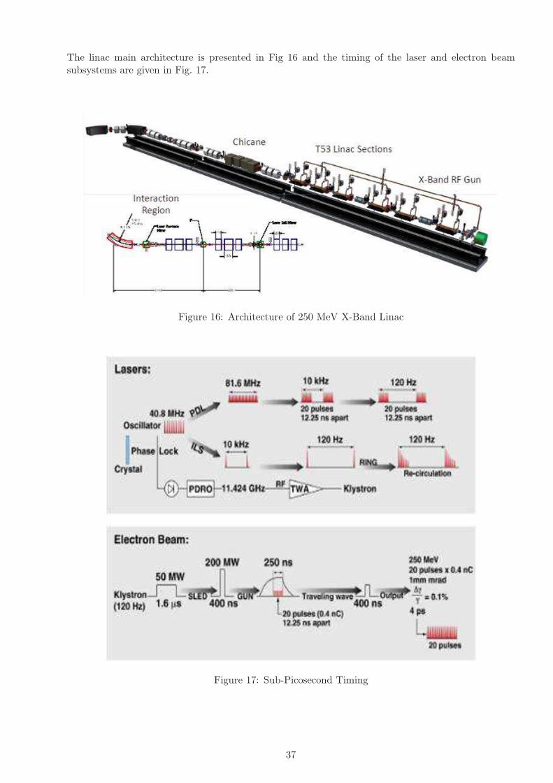
The linac main architecture is presented in Fig 16 and the timing of the laser and electron beamsubsystems are given in Fig. 17.
Figure 16: Architecture of 250 MeV X-Band Linac
Figure 17: Sub-Picosecond Timing
37

Table 8: Technical parameters for the MEGa-ray facility currently being constructed at LLNL.
Quantity Value Units
Peak gamma brilliance 1.5×10²⁰ Photons/sec/mm2/mrad2/(0.1% BW)
Effective Beam repetition 12,000 Hz (100 micro-bunches at 120 Hz rep rate)
Gammas per pulse 8×10⁷ Photons at 100% BW
Spectral beam flux 106 Photons/sec/eV
Gamma pulse duration 2 Picoseconds
Gamma collimation 0.1 mrad at 0.1% BW
Gamma bandwidth 10−3 ∆E/E
Gamma source size 10 microns
Electron beam energy 250 MeV
Laser pulse energy 0.15 Joules
Gamma-ray energy 0.5−2.3 MeV
Figure 18: MEGa-ray Facility
A brief system overview is presented in Table 8 and the facility layout is described in Fig. 18. Theinteraction laser can run reliable at the high repetition rate of 120 Hz using diode pumping. By usinga ring-down cavity for the laser pulse, within the macropulse of 120 Hz repetition rate, 100 micropulsescan be realized, increasing the overall repetition rate to 12 kHz.The predicted spectrum for the LLNL next MEGa-ray machine is shown in Fig. 19.
38

Figure 19: Predicted spectrum of an optimized MEGa-ray source at ∼2.54 MeV.
4.2.2 Specifications of the ELI-NP machine
The ELI-NP machine use identical X-band linac technology but extended from 250 MeV to 600 MeV,use identical state of the art 120 Hz diode pumped laser technology but extended from 1J to 10 Jand duplicate as much as possible the controls systems and hardware being developed for the LLNLmachine. The accelerator structure will be capable of 75 MeV/m in order to avoid higher breakdownrates and higher dark current signals. Specifications for the ELI-NP machine are listed in Table 9.
Table 9: The main specifications of the ELI-NP machine
Quantity Value Units
Peak gamma brilliance >1.5×10²¹ Photons/sec/mm2/mrad2/(0.1% BW)
Effective Beam repetition 12,000 Hz (100 micro-bunches at 120 Hz rep rate)
Gammas per pulse 8×10⁸ Photons at 100% BW
Spectral beam flux 106 Photons/sec/eV
Gamma pulse duration 2 Picoseconds
Gamma collimation 0.1 mrad at 0.1% BW
Gamma bandwidth 10−3 ∆E/E
Gamma source size 10 Microns
Electron beam energy 600 MeV
Laser pulse energy 1.5 Joules
Gamma-ray energy 1−13 (with 532 nm MeV
laser interaction)
This system will incorporate the latest in dark current noise mitigation and a fully documented andvalidated computer control system. It has to be stressed that 12,000 Hz is not the upper limit onrepetition rate for this system and that 10−3 is not the lower limit on bandwidth.Going beyond these points however will require significant R&D that is not included in the estimatesfor the ELI-NP project.Schematic of 600 MeV X-band linac and power distribution system for ELI-NP project is presentedin Fig. 20 and an overall view of the proposed γ-source is presented in Fig. 21.
39

Figure 20: Schematic of 600 MeV X-band linac and power distribution system for ELI-NP project.SLAC XL-4 klystrons and T-53 linac sections are used.
Figure 21: Overall view of the proposed ELI-NP γ source.
40
The proposed solution can be upgraded after 2015 as desired, e.g. by a 100 mA ERL. There is enoughspace to accommodate such an upgrade. Also, with a 355 nm laser instead of the 532 nm one, the γoutput could be brought to 19.5 MeV. The upgrade is not trivial.A number of significant activities are covered under this proposal. These include:1) Development and test of a high energy laser and beam recirculation system which enables a gamma-ray flux that is 100× beyond LLNL’s present machine.
a) Construction of a robust, femtosecond, fiber laser seed source that is synchronized to the linacX-band RF frequency.
b) Construction of a dispersion management system for narrowband chirped pulse amplification.c) Construction of a 10 J-class interaction drive laser system with a base repetition rate of 120 Hz.d) Construction and test of non-linear pulse recirculation hardware.e) Construction and commissioning of a full suite of laser diagnostics.
2) Development of multi-bunch X-band linac technology and hardware for creation of high brightness600 MeV electrons with an effective repetition rate of 12 kHz (see Fig.14).
a) Construction of an all fiber-laser-based photogun drive system synchronized to the linac X-bandRF frequency.
b) Construction of a high brightness, multi-bunch compatible, high gradient X-band photogun.c) Construction of 17 high gradient, X-band linac structures.d) Construction of X-band power and power distribution system consisting of 8 klystrons and
modulators.e) Construction of X-band power pulse compressor for high gradient linac operation.f) Construction of linac beam transport and dark current chicane.g) Construction of laser-electron interaction region.h) Construction and commissioning of a full suite of electron beam diagnostics.
3) Design, test and optimization of laser-electron interactions to maximize flux and/or minimizegamma-ray bandwidth.4) Generation of an integrated computer control system for all components.5) Generation of full construction, operation and maintenance documentation.Four ELI-NP scientists should participate in the R&D, construction and test of the ELI-NP hardwareat LLNL before it is shipped to Romania for installation there.
4.2.3 Possible upgrade in future
The proposed solution can be upgraded after 2015 as desired, e.g. by a 100 mA ERL. There is enoughspace to accommodate such an upgrade.
4.3 Second stage 100 mA Energy Recovery Linac
Energy-recovery linac (ERL) is a new class of accelerator which produces an electron beam of small-emittance and high-average current [6]. In an energy-recovery linac, an electron beam is acceleratedby superconducting rf linac and the beam after use is decelerated in the same linac. Thus the electronenergy is converted back into rf energy and recycled to accelerate succeeding electrons; this is ¨energyrecovery¨.This energy-recovery enables to accelerate an electron beam of high-average current with rf generatorsof small capacity. Moreover, the ERL is free from degradation of electron beam emittance caused bymultiple recirculations of electrons, because an electron bunch in the ERL goes to a beam dump afterdeceleration and another fresh electron bunch is accelerated every turn.The beam emittance of an ERL can be improved by adopting a small-emittance injector such as aphotocathode electron gun. These features, generation of an electron beam with high-average currentand small emittance, distinguish the ERL from other type of accelerators.ERL has been developed for high-power free-electron lasers [7,8] and now is considered as a platformfor future X-ray light sources [9]. The ERL can also work for a high-flux and high-brilliance gamma-raysource in combination with laser Compton scattering as shown in Fig. 22 [10,11]. A small-emittanceelectron beam from the ERL plays an essential role in the generation of high-flux and high-brilliance
41

gamma-ray generation. In the high-brilliance mode, the electron beam, εn= 0.1 mm-mrad, is almostdiffraction limited, and the on-axis gamma-ray bandwidth is dominated by monocromaticity of theelectron beam and has a symmetric spectrum, while the bandwidth in the high-flux mode is dominatedby electron beam emittance and has an anti-symmetric spectrum.
Figure 22: A schematic view of Compton gamma-ray source utilizing an energy-recovery linac (ERL)
Upgrade to 100-mA ERL can be made by adding superconducting ERL cavities under developmentin Japan [12]. After upgrade to 100-mA ERL, we can operate the gamma-ray source with parameters80 pC, 130 MHz for the high-flux mode and 8 pC, 1.3 GHz for the high-brilliance mode. The flux andbrilliance will be enhanced by 2 orders of magnitude.
4.4 Conclusions
Warm linac present and next future technology upgrades could provide for an affordable cost allrequirements imposed by ELI. This facility is expected to be the best γ source worldwide, significantlybetter than the present best facility HIγS. By leveraging the LLNL activities it is believed that theworking components for the ELI-NP machine could be constructed, tested and prepared for shippingto Romania in 3 years from the start of the project, i.e. receipt of funding.Upgrade after 2015 is possible using the existing configuration. For example with 100mA ERL currentone can get a γ flux of 5×10¹⁵ ph/sec and an incredible bandwidth of 4×10⁻⁵.The development with time of the most important parameters of the gamma ray sources (Fig. 23)shows an exponential improvement with time. The planned ELI-NP facility will have the world-widebest gamma source parameters at the start of operation. In the long run with 100 mA ERL’s onecan reach a significantly better bandwidth and peak brilliance for the gamma-beams compared to the2015 approach.
Figure 23: Development with time of the peak brilliance and bandwidth of the gamma ray sources,showing an exponential improvement with time.
42

References
[1] G.Wormser, Gamma Ray Source Working Group, http://www.eli-np.ro/documents/eli-excom-meeting/Wormser-Gamma-ray-source-working-group.pdf
[2] R.Hajima, High-Flux and High-Brightness g-ray Source Based on an Energy-Recovery Linac,http://www.eli-np.ro/executive-comittee-meeting-april-12-13.php ; R. Hajima and N. Nishimori,private communication (2010).
[3] Ch. Barty, Development of MEGaRay technology at LLNL, http://www.eli-np.ro/executive-comittee-meeting-april-12-13.php and private communication (2010)
[4] W.J.Brown et al:”Experimental characterization of an ultrafast Thomson scattering X-ray sourcewith three-dimensional time and frequency-domain analysis” Phys.Rev. ST-AB 7 0607021-1 –060702-12 (2004)
[5] F.Albert et al”Isotope specific detection of low-density materials with laser-based monoenergeticgamma-rays” Opt.Lett.35, 354-356 (2010)
[6] R. Hajima”Current status and future perspectives of energy-recovery linacs”, in Proc. 2009 ParticleAccelerator Conference (2009).
[7] G. R. Neil et al.”Sustained Kilowatt Lasing in a Free-Electron Laser with Same-Cell Energy Re-covery”, Phys. Rev. Lett. 84, 662–665 (2000).
[8] R. Hajima et al.”First demonstration of energy-recovery operation in the JAERI superconductinglinac for a high-power free-electron laser”, Nucl. Instr. Meth. A507, 115–119 (2003).
[9] S.M. Gruner et al.”Energy recovery linacs as synchrotron radiation source”, Rev. Sci. Instr. 73,1402–1406 (2002).
[10] R. Hajima et al.”Detection of radioactive isotopes by using laser Compton scattered γ-ray beams”, Nucl. Instr. Meth. A608, S57–S61 (2009).
[11] V.N. Litvinenko et al., ”Potential uses of ERL-based gamma-ray sources”, IEEE Trans. PlasmaSci. 36, 1799–1807 (2008).
[12] R. Nagai et al., submitted.
43
Glossary
BW - Band Width;CGrAS - Center for Gamma-ray Applied Science;CLIC - Compact LInear Collider;ELI-NP - Extreme Light Infrastructures - Nuclear Physics;ERL - Energy-Recovery Linac;FWHM - Full Width at Half Maximum;HIγS - High Intensity γ (Gamma) Source;LAL - Laboratoire de l’Accelerateur Lineaire;LLNL - Lawrence Livermore National Laboratory;LHC - Large Hadron Collider;LINAC - LINear ACcelerator;MEGa-ray - Mono-Energetic Gamma-ray;PLEIADES - Picosecond Laser Electron Inter-Action for the Dynamic Evaluation of Structures;RF - Radio Frequency;R&D - Research and Development;SLAC - Stanford Linear Accelerator Center;SLED - SLAC Energy Doubler;ThomX - Thomson X-ray Source;T-REX - Thomson -Radiated Extreme X-ray Source.
44

The Scientific Case of ELI Nuclear Physic Pillar
The ELI-Nuclear Physics Experiment working group
Editors:Dietrich Habs, Martin Groß, Nicolae Marginean,Florin Negoita, Peter G. Thirolf, Matthias Zepf
45

Authors
M. Apostol11, P. Boni12, D. Bucurescu11, A.Buta11, Gh. Cata-Danil20, R.Chapman26,27, C.Ciortea11,
F. Constantin11, B. Constantinescu11, V. Corcalciuc11, L. Csige21 L.C.Cune11, B. Dietz5, M.O. Dima11,
G. Dollinger23, D. Dudu11, D. Dumitriu11, N. Elkina3, A. Fedotov10, D. Fluierasu11, M. Fujiwara25,
H. Gies4, M.Ganciu17, C.Ghica19, T.Glodariu11, M. Groß3, M. Gugiu11, I.Gurgu20, D. Habs3,8,
R. Hajima2, M.N. Harakeh18, C. Harvey16, M. Hassan26,27, C.Hategan11, T. Hayakawa1 , T. Heinzl16,
A. Henig3,8, R. Horlein3,8, Ch. Hugenschmidt12, A. Ilderton16, R.A. Ionescu11, C. Ivan11, E. Ivanov11,
D.A. Jaroszynski26, D. Kiefer3,8, U. Koster22, A. Krasznahorkay21, K.W.D. Ledingham26,28,29,
A. Lupascu20, W. Ma6,8, D. Macovei19 , M. Marklund24, N. Marginean11, J. Melone26,28, M. Naumova6,
F. Negoita11, A.Negret11, D. Niculae11, S.Pain26,27, D. Pantelica11 , G. Paulus4, N. Pietralla5,
A.M. Popovici20, N. Puscas20, P.M. Racolta11, A.A. Raduta11,30, G. Rosner26, H. Ruhl3, D. Savran5,
K. Schreckenbach12, J. Schreiber8, R. Schutzhold15, T. Shizuma2, J.F. Smith26,27, K. Sonnabend5,
K.-M. Spohr26,27, M. Stafe20, C.M.Teodorescu19, P. G. Thirolf3, C.A.Ur11,31, G. Vaman11, I. Vata11,
A.M. Vlaicu19, H.A. Weidenmuller9, X.Q. Yan8,14, N.V. Zamfir11, M. Zepf13.
Affiliations
1 Advanced Photon Research Center, JAEA, Kizugawa, Kyoto, Japan2 Advanced Photon Research Center, JAEA, Tokai, Ibaraki, Japan3 Fakultat fur Physik, Ludwig-Maximilians-Universitat Munchen, Munich, Germany4 Friedrich Schiller Universitat, Jena, Germany5 Institut fur Kernphysik, TU Darmstadt, Darmstadt, Germany6 Institute of Physics, CAS, Beijing, P.R. China7 Laboratoire d’Optique Appliquee, UMR 7639 ENSTA, Palaiseau, France8 Max-Planck Institute of Quantum Optics, Garching, Germany9 Max-Planck Institut fur Kernphysik, D-69029 Heidelberg, Germany10 Moscow Engeniering Physics Institute, Moscow, Russia11 National Institute for Physics and Nuclear Engineering, Bucuresti-Magurele, Romania12 Physik-Department E21, Technische Universitat Munchen, Garching, Germany13 Queen’s University, Belfast, Northern Ireland, UK14 State Key Lab of Nuclear Physics and Technology, Peking University, Beijing, P.R. China15 Universitat Duisburg-Essen, Duisburg, Germany16 University of Plymouth, Plymouth, PL4 8AA, UK17 National Institute for Laser Plasma and Radiation Physics, Bucuresti-Magurele, Romania18 Kernfysisch Versneller Instituut, Zernikelaan 25, NL-9747 AA Groningen, The Netherlands19 National Institute for Materials Physics, Bucuresti-Magurele, Romania20 Polytechnic University, Bucuresti, Romania21 MTA, ATOMKI Debrecen, Hungary22 ILL, Grenoble, France23 University of the Bundeswehr, Munich, Germany24 Umea University, Umea, Sweden25 Osaka University, Osaka, Japan26 Scottish Universities Physics Alliance, SUPA,
27 Faculty of Engineering and Science, University of the West of Scotland, Paisley, PA1 2BE, United
Kingdom28 Department of Physics, University of Strathclyde, Glasgow, G4 0NG, United Kingdom29 AWE, Aldermaston, Reading, Berkshire, RG7 4PR, United Kingdom30 Academy of Romanian Scientists, 54 Splaiul Independentei, Bucharest 050094, Romania31 Istituto Nazionale di Fisica Nucleare, Sezione di Padova(Italy)
47

5 The Scientific Case of ELI Nuclear Physic Pillar
5.1 Introduction to Envisioned Experiments at ELI Nuclear Physics Facility
ELI Nuclear Physics is meant as an unique research facility to investigate the impact of very intenseelectromagnetic radiation (Extreme Light) on matter with specific focus on nuclear phaenomena andtheir practical applications. The extreme light is realized at ELI-NP in two ways: by very high opticallaser intensities and by the very short wavelength beams on γ-ray domain with very high brilliance.This combination allows for stand-alone experiments with a state-of-art high-intensity laser, stand-alone high resolution γ-beam experiments or combined experiments of both photon sources. In thisway it will be possible to approach a broad range of frontier research topics of modern physics, asthe production and study of radioactive species important to understand the genesis of elements inUniverse which cannot be produced at existing radioactive-beam facilities or under construction, theinvestigation of rare processes taking advantage of the acceleration of compact bunches of matterwith high-intensity lasers or the study of photonuclear processes using an unique tunable energy,high-resolution γ-ray beams.The ELI-NP high-intensity laser will be based on APOLLON-type solution and will use OPCPAtechnology at the front-end and Ti:Sapphire high-energy amplification stages. The APOLLON-typehigh-intensity laser at ELI-NP facility will have two front-ends, which will temporally stretch andamplify initial ultrashort pulses with 800 nm central wavelength to the 100 mJ level, preserving theneeded large bandwidth of the 15 fs laser pulses and the temporal contrast of the pulses in the rangeof 10−12.The pulses after the front end will be splitted and distributed to further laser amplifiers, reaching fewJules of energy at 10 Hz repetition rate and few tens of Joules at a repetition period of the order offew seconds. At these energy levels, the pulses can be extracted from the laser amplification chainand recompressed to shortest duration in vacuum compressors. Subsequently, they are distributed tothe high repetition rate experimental areas.Alternatively, the laser pulses will be further amplified in the amplification chains to energies ofthe order of 300 J. The repetition rate of the pump lasers will restrict the repetition period of thehigh energy pulses to the minutes range. Adaptive optics and optical isolation of the pulses willbe implemented before the optical mosaic compressors. The ultrashort pulses will be distributedto the high energy experimental areas, where stand-alone experiments or combined nuclear physicsexperiments using the highly brilliant γ beam will be performed.Coherent combination of the high power ultrashort pulses with the ultraintense and ultrashort pulsesfrom the parallel amplification chains is envisaged, in order to reach intensities of the order of 1023
W cm−2 and above. The operation of the experiments will take place in parallel, the laser pulsesbeing delivered to different experimental areas on request. Depending on technological developments,an upgrade of the high-intesity laser system in a second stage might be possible, allowing to obtainintensities above 1024 W cm−2.The γ source of ELI-NP will produce a very intense and brilliant γ beam (Eγ = 14 -16 MeV forthe beginning and Eγ ≤ 19 MeV in a second stage), which is obtained by incoherent Compton backscattering of direct laser light with a very brilliant and intense electron beam (Ee ≤ 0.6 GeV).The experiments envisaged with the γ source definded severe constraints for the parameters of the γbeam: bandwidth equal or higher than 10−3, energy up to 19 MeV to access all GDR, repetition ratein the range of kHz to get about 1 event/pulse in the detector, total flux higher than 1013 photons/sec,peak brilliance higher than 1022 photons mm−2 mrad−2 s−1 (0.1% BW)−1 in order to improve the ratioeffect-background; the high flux and superb brilliance requires an excellent normalized emittance forthe electron beam (in the range of 0.25 mm mrad). The solution adopted for producing the 600 MeVelectron beam is to use a 120 Hz warm LINAC accelerator, similar with the accelerator foreseen forthe MEGa-ray project of LLNL. The reflective laser for the production of γ-rays will run reliable atthe high repetition rate of 120 Hz using diode pumping. By using a ring-down cavity for the laserpulse, within the macropulse of 120 Hz repetition rate, 100 micropulses can be realized, increasing theoverall repetition rate to 12 kHzUpgrade to 100-mA ERL will be possible in a second stage, by adding superconducting ERL cavities
48
currently under development in Japan. After upgrade to 100-mA ERL, it will be possible operate thegamma-ray source with parameters 80 pC, 130 MHz for the high-flux mode and 8 pC, 1.3 GHz forthe high-brilliance mode. Consequently, the flux and brilliance will be further enhanced by 2 ordersof magnitude, paving the way toward new experimental challenges at the frontier of physics.
5.2 Experiments with the APOLLON-type Laser used stand-alone
The APOLLON-type laser beam will not produce effects on nuclear dynamics directly, but the laserwill be used for ion acceleration or to produce relativistic electron mirrors by laser acceleration followedby a coherent reflection of a second laser beam in order to generate very brilliant X-ray or γ beams.We plan to use these beams later to produce exotic nuclei or to perform new γ spectroscopy exper-iments in the energy or time domain. Most of the experiments proposed in this subsection may bedone, with some limitations, at laser intensities of 1023 W/cm2, and several other experiments requirelaser intensity of 1024 W/cm2. The production of the electron sheet as relativistic mirror needs laserintensity of 1024 W/cm2, and the fission-fusion mechanism to produce neutron-rich nuclei can be in-vestigated as proof-of-principle at 1023 W/cm2, but the real production experiments require intensitiesof 1024 W/cm2 and greater.
5.2.1 Production of Neutron-Rich Nuclei around the N = 126 Waiting Pointof the r-Process via the Fission-Fusion Reaction Mechanismusing a Laser-Accerated Th Beam
D. Habs1 and P.G. Thirolf11 Ludwig Maximilians University, Munich (Germany)
According to a recent report by the National Research Council of the National Academy of Science(USA), the origin of the heaviest elements remains one of the 11 greatest unanswered questions ofmodern physics [1]. While the lower path of the r-process for the production of heavy elements is wellexplored, the nuclei around the N = 126 waiting point critically determine this element productionmechanism, and at present basically nothing is known about these nuclei. We propose to produceneutron-rich nuclei in the range of the astrophysical r-process (the rapid neutron-capture process)around the waiting point N = 126 [2–4] by fissioning a dense thorium ion bunch with about 7 MeV/uin a ca. 3 mm thick thorium target (covered by a thin carbon layer), where the light fission fragments ofthe beam fuse with the light fission fragments of the target. Via laser Radiation Pressure Acceleration(RPA) [10, 11] we are able to produce very efficiently bunches of solid state density of 232Th withabout 7 MeV/u, which pass through a thin carbon layer and desintegrate into light and heavy fissionfragments. In addition light ions (H,C) from the CH2 backing of the first Th target will be acceleratedas well, inducing the fission process of 232Th in the second, thick Th foil. The expected stronglyreduced stopping power for these very dense ion bunches helps to obtain intense fission fragmentbeams. The high density of the bunch and the target furthermore leads to a reasonable fusion yield.In contrast to classical radioactive beam facilities, where intense, low density radioactive beams ofone isotope are merged with stable targets, we here study the fusion between neutron-rich short-lived target-like nuclei and neutron-rich, short-lived projectile-like nuclei. Since each of these massdistributions consists of a multitude of isotopes, we exploit the fluctuations in neutron number of bothtarget and beam fragment to reach more neutron-rich nuclei. Also the neutron transfer before thefirst fission reaction will increase the fluctuations in neutron number of the light fission fragments.The new acceleration scheme allows to reach this so far unexplored region of neutron-rich nuclei withimportance to nuclear physics and astrophysics. One expects for the 20 PW APOLLON-type laserwith 300 J about 1012 accelerated thorium ions with a 9 µm beam diameter, 30 nm bunch length and0.1 Hz repetition rate. This should result in about 105 − 106 ions/shot of fused neutron-rich nucleiwith masses close to A = 180 − 190. In a velocity filter the other species with A ≈ 232, A ≈ 140and A ≈ 100 can be separated from the beam-like nuclei of interest with A = 180 − 190. Since theyield of very neutron-rich fusion products grows strongly nonlinearly with laser energy, a final use ofseveral coincident APOLLON-like lasers could be very advantageous, especially since the detection ofthe new ms-isotopes should be rather straightforward.
49

Radiation Pressure Acceleration (RPA) with solid state density ion bunches, which are about 1015
times more dense than classically accelerated ion bunches, allows for a high probability that generatedfission products fuse again, when the thorium beam strikes a second close Th target. The fissionfragments have a 1/sin(Θ) angular distribution and thus are predominantly emitted in beam directionand stay within the cylinder volume defined by the small spot diameter of the first Th target. In thistwo-step reaction neutron-rich light fission fragments of the beam fuse with neutron-rich light fissionfragments of the target and we can reach more neutron-rich nuclei than with classical radioactivebeams only. The produced beam of new radioactive nuclei will be analyzed with a (gas-filled) recoilseparator, where the technical optimization is well known and one gets a very good suppression ofbackground for nearly symmetric fusion reactions. The small repetition rate of the 20 PW APOLLON-type lasers of about 0.02 Hz with very short production pulses is stretched by the β-decay half-livesof the produced nuclei to counting rates acceptable to nuclear detectors. Very neutron-rich nuclei stillhave small production cross sections, because weakly bound neutrons (BN ≥ 3 MeV) are evaporatedeasily. It is important that the hindrance of fusion for nearly symmetric systems (break-down offusion) only sets in for projectile and target masses heavier than 100 u [8, 9]. Thus for the fusion oflight fission fragments we expect an unhindered fusion evaporation process. The velocity filter has tosuppress the many fused nuclei close to the valley of stability. Here we want to look specifically fornuclei close to the waiting point at N = 126 of the r-process, which is decisive for the astrophysicalproduction of heavy elements and was not accessible until now. We estimate sufficient rates for theseinteresting nuclei. We envision having behind the velocity filter a gas stopping cell for the preparationof the ions [10] prior to their injection into a Penning trap [11], where nuclear masses can be measuredwith high accuracy, thus giving access to nuclear binding energies.
References
[1] E. Haseltine, http://discovermagazine.com/2002/feb/cover
[2] K.L. Kratz et al., Prog. in Part. and Nucl. Phys. 59, 147 (2007).
[3] M. Arnould, S. Griely, K. Takahashi, Phys. Rep. 450, 97 (2007).
[4] I.V Panov and H.-Th. Janka, Astr. Astroph. 494, 829 (2009).
[5] A. Henig et al., Phys. Rev. Lett. 103, 245003 (2009).
[6] T. Tajima, D. Habs, X. Yan, Laser Acceleration of Ions for Radiation Therapy, RAST 2, 221(2009).
[7] G. Munzenberg et al., Nucl. Instr. Meth. 161, 65 (1979).
[8] A.B. Quint et al., Z. Phys. A 346, 119 (1993).
[9] W. Morawek et al., Z. Phys. A 341, 75 (1991).
[10] J.B. Neumayr et al., Nucl. Instr. Meth. B244, 489 (2006).
[11] M. Block et al., Nature 463, 785 (2010).
50

5.2.2 From Radiation Pressure Acceleration (RPA) and Laser-Driven Ion Pistonsto Direct Laser Acceleration of Protons at Intensities up to 1024W/cm2
D. Habs1, A. Henig1, J. Schreiber1, R. Horlein1, X.Q. Yan2 and M. Zepf31 Ludwig Maximilians University, Munich (Germany)2 State Key Lab of Nuclear Physics and Technology, Peking University, Beijing, (P.R. China)2 Queen’s University Belfast, Northern Ireland (UK)
Since the pioneering work that was carried out 10 years ago [1–4], the generation of highly energeticion beams from laser-plasma interactions has been investigated in much detail in the regime of targetnormal sheath acceleration (TNSA) [5]. Creation of ion beams with small longitudinal and transverseemittance and energies extending up to tens of MeV fueled visions of compact, laser-driven ion sourcesfor applications such as ion beam therapy of tumors, fast ignition inertial confinement fusion or thegeneration of neutron-rich nuclei. However, new pathways are of crucial importance to push the currentlimits of laser-generated ion beams further towards parameters necessary for those applications.To overcome the limitations of TNSA, a novel mechanism which is referred to as Radiation PressureAcceleration (RPA) was proposed [6–9]. Here, much thinner foil targets of only nanometers are usedso that the laser transfers energy to all electrons located within the focal volume. While for TNSA theaccelerating electric field that is generated by hot electrons is stationary and ion acceleration is spatiallyseparated from laser absorption into electrons, in RPA a localized longitudinal field enhancementis present that co-propagates with the ions as the accompanying laser pulse pushes the electronsforward. By changing the laser polarization to circular, electron heating and expansion are efficientlysuppressed, resulting in a phase-stable acceleration that is dominated by the laser radiation pressureand is maintained for an extended time. Thus, the whole target is accelerated ballistically as a quasi-neutral, dense plasma bunch like a light sail. Just recently, this novel acceleration process has beenobserved for the first time in an experiment at intensities of 5×10¹⁹ W/cm2 [10,11] and pulse energiesbelow 1 J, generating a peaked spectrum of C6+ ions. Compared to quasi-monoenergetic ion beamgeneration within the TNSA regime [12], a more than 40 times increase in conversion efficiency wasachieved.A large number of theoretical studies lately predicted further improvement of the ion beam character-istics in terms of conversion efficiency as well as peak energy and monochromaticity when significantlyhigher laser pulse energies and intensities are used [13–17]. In particular, it is expected that the RPAprocess progresses much more stably when ions reach relativistic velocities already in the initial hole-boring phase before the whole target is set in motion (i.e., before the light sail stage). At intensitiesaround 1023 W/cm2 simulations show that protons become relativistic within one half-cycle of the laserpulse and acceleration by the laser radiation pressure is dominant even for linear polarization in whatis referred to as the laser-piston regime [18,19]. Here, the target can be viewed as a relativistic plasmamirror with Lorentz factor γ being propelled by the reflected laser and the laser-to-ion conversionefficiency η = 1 − 1/(4γ2) approaches unity in the ultrarelativistic limit.In all ion acceleration mechanisms discussed so far, the laser energy was not directly transfered toions but mediated by electrons instead. For even higher laser intensities of ∼ 5 × 1024 W/cm2 at awavelength of 1 µm, protons can be driven to relativistic velocities directly by the laser field. Thisregime of direct ion acceleration has not been studied in simulations so far since the new phenomenonof radiation damping strongly changes the laser-plasma interaction and is also expected to occur at1024 W/cm2, hence preventing the straightforward application of existing PIC codes [20,21]. Basicallyall theories of radiation damping suffer from more or less severe intrinsic inconsistencies [22] and onlyby comparison with experiment the proper theory can be established.Employing the APOLLON-type laser unprecedented intensities on the order of 1024 W/cm2 becomeavailable for experiments, allowing for improved RPA and for the first time study of the laser-pistonregime as well as direct proton acceleration. According to theory, mono-energetic solid density ionbunches are expected at laser-to-ion conversion efficiencies approaching unity. Such a novel compaction source could serve a wealth of experiments and applications, with an example being given by theproduction of neutron-rich nuclei around the N=126 waiting point as described in project 4.1.
51

References
[1] E. L. Clark et al., Phys. Rev. Lett. 85(8), 1654–1657 (2000).
[2] A. Maksimchuk et al., Phys. Rev. Lett. 84(18), 4108–4111 (2000).
[3] R. A. Snavely et al., Phys. Rev. Lett. 85(14), 2945–2948 (2000).
[4] S. P. Hatchett et al., Phys. Plas. 7(5), 2076–2082 (2000).
[5] S.C. Wilks et al., Phys. Plasma 8, 542 (2001).
[6] A. Macchi et al., Phys. Rev. Lett. 94(16), 165003 (2005).
[7] O. Klimo et al., Phys. Rev. ST Accel. Beams 11, 031301 (2008)
[8] A.P.L. Robinson et al., New J. of Phys. 10, 013021 (2008).
[9] X. Q. Yan et al., Phys. Rev. Lett. 100(13), 135003–4 (2008).
[10] A. Henig et al., Phys. Rev. Lett. 103, 245003 (2009).
[11] T. Tajima, D. Habs, X. Yan, Laser Acceleration of Ions for Radiation Therapy, RAST 2, 221(2009).
[12] B. M. Hegelich et al., Nature, 439, 441–444 (2006).
[13] X. Q. Yan et al., Phys. Rev. Lett., 103(13), 135001 (2009).
[14] B. Qiao et al., Phys. Rev. Lett. 102, 145002 (2009).
[15] A.P.L. Robinson et al., Plasma Phys. Control Fusion 51, 024004 (2009).
[16] A. Macchi et al., Phys. Rev. Lett. 103, 085003 (2009).
[17] A. Macchi et al., Radiation pressure acceleration of ultrathin foils, New J. Phys. (2010), in press.
[18] T. Esirkepov et al., Phys. Rev. Lett. 92, 175003 (2004).
[19] F. Pegoraro and S.V. Bulanov, Phys. Pev. Lett. 99, 065002 (2007).
[20] T. Schlegel et al., Phys. Plas., 16, 083103 (2009).
[21] M. Chen et al., Radiation reaction effects on ion acceleration on laser foil acceleration,arXiv:0909.5144v1(2009).
[22] I.V. Sokolov, JETP 109, 207 (2009).
52

5.2.3 Deceleration of Very Dense Electron and Ion Beams
D. Habs1, A. Henig1, J. Schreiber1, R. Horlein1, W. Ma2 and M. Zepf3, D.Dumitriu4,C.Ciortea4, M.Gugiu4, D. Fluerasu4
1 Ludwig Maximilians University, Munich (Germany)2 Institute of Physics, CAS, Beijing, (P.R. China)3 Queen’s University Belfast, Northern Ireland (UK)4 IFIN-HH, Bucharest, Romania
In nuclear physics the Bethe-Bloch formula [2] is used to calculate the atomic stopping of energeticindividual electrons [1] by ionization and atomic excitation:
−[dE
dx]I = K · z2 Z
A
1
β2
[
1
2ln
2mec2β2γ2Tmax
I2− β2 − δ
2
]
(1.1)
and ions:
−dE
dx= 4πne
Z2eff e4
mev2(4πǫ0)2
[
ln
(
2mev2
I(1 − β2)
)
− β2
]
(1.2)
where I is the ionization potential, ne the density of the electrons, me the mass of the electron, vis the ion velocity, β = v/c, Tmax is the maximum kinetic energy which can be imparted to a singleelectron in a single collision, and Zeff is the effective charge of the ions.For relativistic electrons the other important energy loss is bremsstrahlung with:
−[dE
dx]R = (4πne/(mec
2))Z
137π(γ − 1)ln(183Z−1/3) (1.3)
The approximate ratio of the two loss processes [2] is:
[dE
dx]I/[
dE
dx]R = EZ/1600mc2 (1.4)
Thus radiation loss is dominant for high energy electrons e.g. E≥ 100 MeV and Z=10. If, however (seebelow), the atomic stopping becomes orders of magnitude larger by collective effects, the radiationloss can be neglected.For laser acceleration the electron and ion bunch densities reach solid state densities, which are about15 orders of magnitude larger compared to beams from classical accelerators. Here collective effectsbecome important. One can decompose the Bethe-Bloch equation according to Ref. [3] into a firstcontribution describing binary collisions and a second term describing long range collective contribu-tions:
−dE
dx= 4πne
Z2eff e4
mev2(4πǫ0)2[
ln(mev2/e2kD) + ln(kDv/ωp)
]
(1.5)
Here kD is the Debye wave number and ωp is the plasma frequency of the electrons. Similar to bubbleacceleration [4] but now with opposite phase for deceleration a strong collective field is built up by theblown-out electrons that decelerates them much faster than the processes that take effect for individualcharged particles. Typical electric fields E are:
E = meωp · v · nb
ne e(1.6)
where nb is the charge density of the bunch. In Ref. [6] we discuss this mechanism of collectivedeceleration of a dense particle bunch in a thin plasma, where the particle bunch fits into part of theplasma oscillation and is decelerated 105 − 106 stronger than predicted by the classical Bethe-Blochequation [2] due to the strong collective wakefield. For ion deceleration we want to use targets with
53

suitable low density. These new laws of deceleration and stopping of charged particles have to beestablished to use them later in experiments in an optimum way.We may also discuss the opposite effect with a strongly reduced atomic stopping power that occurswhen sending an energetic, solid state density ion bunch into a solid target. For this target theplasma wavelength (λp ≈1 nm) is much smaller than the ion bunch length (≈ 100 nm) and collectiveacceleration and deceleration effects cancel each other. Only the binary collisions are important.Hence, we may consider the dense ion bunch as consisting of 300 layers with A distances. Here thefirst layers of the bunch will attract the electrons from the target and – like a snow plough – willtake up the decelerating electron momenta. The predominant part of the ion bunch is screened fromelectrons and we expect a ≈ 102 fold reduction in stopping power. The electron density ne is stronglyreduced in the channel because many electrons are driven out by the ion bunch and the laser. Againall these effects have to be studied in detail.It is expected that the resulted very dense electron and ion bunches should have a time evolution(decay in time) and the decay products are emitted at different times and angles. Therefore, forcharacterization of the dense bunches and their time evolution, the detection system need to capturethe decay products, emitted at different times (analogous to time of flight measurements), and measuretheir angular distributions. Of course, the temporal evolution which can be followed vary greatlydepending on the temporal resolution of the diagnosis system. In a preliminary phase, it is expectedthat electrons and ions are emitted due to the Coulomb explosion of a part of the initially formedbunch (pre-bunch emission) . Then, the remained bunch will have a slower temporal evolution, whichcan be followed in dependence of its time of flight in free space. The experimental study of decelerationof dense, high speed bunches of electrons and ions will require:
• Bunch’s characterization in free space: its components, their energies and the ion charge states,their angular distribution and temporal evolution; due to the large number of particles, thedetection solid angles must be small (of the order of 10−7 sr or less).
• Tracking the changes introduced by bunch’s passing through different materials (solid or gas)and their deceleration study. Studies will be carried out depending on laser power and targettype and thickness and for deceleration - depending on material type and its thickness.
The same detection system could be used for both diagnosis in free space and diagnosis after passingthrough a material. A rapid characterization may be done with a Thomson parabola ion spectrometer,and an electron magnetic spectrometer, implying measurements of the emissions at different times andpossibly their angular distribution, in the case they are relevant. A more complete analysis will requirea diagnosis system working in real-time, using magnetic spectrometers and detection systems with highgranularity or with position sensitive reading in the focal plane (e.g., stacks of∆E-E detectors, withionization chambers and Si or scintillation detectors). Even if the laser pulse frequency is small, thenuclear electronics can be triggered in the usual way.
References
[1] Particle Data Group, Phys. Rev. D 66, 010001 (2002).
[2] S. Segre, Nuclei and Particles, 2nd edition, W.A. Benjamin, RA, London (1977)
[3] S. Ichimaru, Basic Principles of Plasma Physics: A Statistical Approach, Benjamin, Reading, MA(1973).
[4] A. Pukhov and J. Meyer-ter-Vehn; Appl. Phys. B74, 355 (2002).
[5] H. -C. Wu et al., Collective Deceleration, arXiv:0909.1530v1 [physics.plasm-ph] (2010).
54

5.2.4 The development and application of ultra-short duration high brilliancegamma rays probes for nuclear physics
D.A. Jaroszynski1, G.Rosner1, M.Ganciu2, N.V. Zamfir3,Gh.Cata-Danil3, NMarginean3
1 Scottish Universities Physics Alliance, SUPA,2 Institute of Lasers, Plasma and Radiation, Bucharest-Magurele (Romania)3 National Institute for Physics and Nuclear Engineering, Bucharest-Magurele (Romania)
The radiation sources that will be set up in the ELI-NP Bucharest laboratory will provide uniqueprobes for investigating the structure of matter on unprecedented temporal and spatial scales. Inaddition, they could provide users with the means to create ”extreme” states of matter. An importantlong term objective of the ELI project will be to produce very intense electric fields, approaching1017 V/m, where QED effects become evident. Furthermore, the proposed narrow bandwidth gammasources based on Compton back-scattering will give unique opportunities to investigate nuclear struc-ture and nuclear processes.To provide the groundwork for the teams enable them to take advantage of the proposed ELI facilitieswe will set up a collaborative Scottish-Romanian programme, which includes a strong training elementdrawing on the expertise in nuclear, plasma, accelerator physics of the two teams, to develop the newtechniques that are necessary to probe matter using gamma rays and ultra-short duration bright elec-tron bunches. This programme will include the development of high brilliance femtosecond durationgamma ray sources based on the laser-plasma wakefield accelerator. The source development, whichis currently part of the Strathclyde team’s ALPHA-X project, will include scaling up of a betatronlaser-wakefield radiator from the current 200 keV (600 keV critical photon energy) to the range of 1–10MeV, and beyond. This will be achieved by increasing the energy of the beams from the laser-drivenplasma wakefield accelerator to several GeV by lowering the plasma density and increasing the laserintensity. The measured peak brilliance is currently in excess of 1022 phot/sec/mm2/mrad2/0.1%BW. This will be increased by several orders of magnitude when the photon energy is scaled up to the1-10 MeV range. The expected photon flux should be in the range of 1010–1012 photons/s dependingon the laser repetition rate. The proposed experimental work will be carried out initially using thecurrent 30 TW ALPHA-X laser, and then on the new SCAPA 200–300 TW laser, which will becomeoperational in 2011-2012. The femtosecond duration polarised gamma ray source should provide aunique opportunity for developing new radiation delivery methods (focussing), time dependent pump-probe techniques and detectors necessary for the future ELI nuclear physics programme. It will alsoprovide a very useful complementary source to the proposed Compton backscatter source because ofits unique time structure. Furthermore, the electron bunches, with energies up to several GeV, couldalso be used directly in nuclear experiments.One aspect of the programme will be collaboration in the development of the plasma media necessaryfor supporting the high electrostatic fields, and the transport of the ultra-short electron bunches.In addition to building on the existing collaboration between the Scottish and Romanian teams wewill enlarge the collaboration to include all interested parties. It is the intention to provide trainingopportunities not only for new students and postdoctoral researchers entering this new and excitingfield but also for the more senior scientists who will require retraining to develop new expertise in thisrapidly evolving field. It is clear that to take full advantage of the new facilities new expertise will beneeded in Romania. The hope is that this collaboration will help to provide this training while alsogrowing competence within the wider ELI consortium.An important adjunct to the source and technique development part of the collaboration is the de-velopment of a solid scientific applications programme. There are many opportunities that could beexplored. With a view to furthering the overall goals of the ELI-NP project the Scottish-Romanianteams will use the radiation and particle beams at Strathclyde to carry out several initial studies ofphoto-nuclear isotope generation, which could have an impact on the development of new methods forthe treatment of nuclear waste, or for the manufacture of medical isotopes. The gamma ray energyrange of 1–15+ MeV covers several interesting spectral regions from giant to pigmy dipole resonances.Even though the relatively broad spectral width of betatron sources may not be immediately usefulfor directly studying these photonuclear processes spectroscopically, there are opportunities that take
55

advantage of the short temporal duration of the gamma ray pulses, which is of the order of 1 fem-tosecond, and could be decreased to several attoseconds. Another important part of the collaborationwill include the study of radiation reaction in highly radiating systems such as betatron radiation inion channels and also the collective scattering processes in plasma using the ultra-short duration highpeak brightness and dense electron bunches from wakefield accelerators.
5.2.5 A Relativistic Ultra-thin Electron Sheet used as a Relativistic Mirrorfor the Production of Brilliant, Intense Coherent γ-Rays
D. Habs1,2, D. Kiefer1,2, R. Horlein1,2 and X.Q. Yan2,3
1 Ludwig Maximilians University, Munich (Germany)2 Max-Planck Institute of Quantum Optics, Garching (Germany)2 State Key Lab of Nuclear Physics and Technology, Peking University, Beijing, (P.R. China)
In Ref. [1] we have proposed the use of an intense laser to drive a very dense electron sheet out ofan ultra-thin Diamond-Like-Carbon (DLC) foil. The sheet then surfs on the half-wave of the laserpulse and gains a relativistic energy characterized by γ = 1/
√
1 − β2 with the total velocity β = v/c.We also introduce γx = 1/
√
1 − β2x with the velocity βx = vx/c normal to the electron sheet. This
relativistic electron mirror is expected to allow the reflection of a second laser beam for very brilliant,very intense, coherent X ray and γ beams with many unique applications.Kulagin et al. [2, 3] showed that the produced flat electron sheet stays together for some µm, havingenergies of γ ≈ a, where a is the dimensionless laser intensity parameter. This γ is different from theγ = 1 + a2/2 calculated for a single electron, which probably is to high for a dense electron sheet. Wehave experimentally observed this production of electron sheets for the first time at the Trident laserin Los Alamos for 500 fs laser pulses [4] and also at the laser of the Max Born Institute in Berlin withtheir 35 fs laser pulses [5].If one would reflect optical photons of energy E0 = 1 eV normally from this electron sheet withan energy characterized by γx, one naively would expect to obtain reflected γ photons of energyEγ = 4 · γ2
x · E0. However, Wu et al. [6, 7] showed that the electron sheet also acquires a transverse
velocity component vx from the transverse laser E-field. Only later the ~v × ~B force leads to thedominant forward acceleration. The transverse velocity causes a much smaller Doppler boost of thereflected γ photons of Eγ = 4 · γ2
x · E0 = 2 · γ · E0, where γ is the total γ. However, recently Wuet al. [8] showed that one should place a second foil of about 2 times the skin depth (15 nm) ina 1-2 µm distance behind the first target foil, where the accelerating laser pulse is reflected. Thereflected laser pulse completely cancels the transverse velocity component vx, but basically leaves thelongitudinal velocity component unchanged. In this way the originally expected full Doppler boost ofthe γ photons with Eγ = 4 · γ2E0 is recovered. While the preliminary simulations of Wu et al., [8] arevery impressive more realistic ultrathin foils with much larger ne/nc for 1nm foils are required. Thepresent simulations correspond to independent individual electrons, while then collective effects likeexpansion of the foil become important.We invented a special target design with ultra-thin DLC foils and a very low-density carbon nanotubetarget as a spacer inbetween, in order to realize such a target for a perfectly reflecting electronsheet. The dense electron sheet then traverses the reflector target and shortly behind the reflector isbombarded with the second laser pulse (split off from the APOLLON-type laser with wavelength λ0)to produce the γ photons with λγ = λ0/4γ
2. The thickness d of the electron sheet determines up towhich γ energy a coherent reflection occurs. In the inner rest frame of the electron sheet the photonshave the wavelength λi = λ0/2γ before reflection. The requirement is λi/2 ≤ d. Possibly the electronsheet is compressed during acceleration and also by the interaction with the reflected laser, reducingthe thickness d. If we use d = 1 nm and λ0 = 1 µm and γ = 250, we obtain reflected γ-photons of≈ 250 keV. These γ pulses would be coherent and would have a pulse length of a few zeptoseconds.Since we will have about N ≈ 109 − 1010 coherently reflecting electrons, the reflected amplitude isincreased by N . If we assume a spot diameter of the reflected laser pulse of 3 µm, we obtain a largereflectivity (1%) and expect due to the energy conservation of the laser accelerated electron sheet≈ 1014 γ/shot with (6 µm)2, (≈ 5 mrad)2, 10−20 s and 0.1 % BW. Thus a rough estimate of the
56

peak brilliance is 1037/[s (mm mrad)2 0.1 %BW]. With the APOLLON-type laser we easily can realizea = 250, but require in addition a very high contrast of 1016 for the survival of ultrathin foils duringthe prepulse. In this context careful experimental studies have to be performed aiming to characterizepotential effects of reflectivity modifications by distortions of the reflecting mirror foil during the laserinteraction.In Ref. [9] we showed that a much larger reflecting force should occur, since the transition from theLorentz force to the radiation damping force is strongly enhanced. While the Lorentz force scales withcharge e, the radiation damping force or Landau-Lifshitz term scales with (2
3e3
mc3) [10] und thus if N
electrons act coherently, the Lorentz force is proportional to N , while the Landau-Lifshitz force scaleswith N2 and thus one obtains an acceleration due to radiation damping which is N fold enhanced.Thus 102 larger γ-energies may be reflected, reaching energies in the 25 MeV range. Here the ensembleof all electrons reflects like one macro-particle, which then takes up the recoil momentum as a whole.The electron sheet is trapped between the potential of the strongly reflecting laser and the Coulombpotential of the more backward layers of the electron sheet. This binding together of the electrons to amacroparticle is essential to result in a Mossbauer-like reflection scenario. If the Landau-Lifshitz forcebecomes dominant and higher order terms of the Landau-Lifshitz expansion series become important,even higher orders of N become relevant.If these coherent intense γ pulses become available, many proposed experiments of ELI-NP withthe incoherent γ beam like pair creation from the vacuum or excited multiple nuclear excitons willgive orders of magnitude better results. Furthermore pump-probe experiments with two consecutiveexcitations of nuclei will become possible, which open a new field of studying highly excited statesdescribed by random matrix theory [6].
References
[1] D. Habs et al., Appl. Phys. B 93, 349 (2008).
[2] V.V. Kulagin et al., Phys. Rev. Lett. 99, 124801 (2007).
[3] V.V Kulagin et al., Phys. Rev. E 80 , 016404 (2009).
[4] D. Kiefer et al., Eur. Phys. J. D 55, 427 (2009).
[5] D. Kiefer et al., to be published.
[6] H.-C. Wu and J. Meyer-ter-Vehn., Eur. Phys. J. D 55, 443 (2009).
[7] J. Meyer-ter-Vehn and H.-C. Wu, Eur. Phys. J. D 55, 433 (2009).
[8] H.-C. Wu et al., Laser-like X-Ray Sources Based on Optical Reflection from Relativistic ElectronMirror, arXiv:1003.1739v2 (2010).
[9] D. Habs et al., Proposed studies of radiation damping in laser interaction with an ultra-thin coher-ently refelcting electron sheet, regarded as a macro-particle, ,Brasov Romania Conference, AIP1228,287 (2009).
[10] L.D. Landau and E.M. Lifschitz; Klassische Feldtheorie, Volume 2, chapter 76, Verlag HarriDeutsch, 1992.
[11] J.Z. Gu and H.A. Weidenmuller, Nucl. Phys. A 690, 382 (2001).
57

5.2.6 Nuclear Techniques for Characterization of Laser-Induced Radiations
D.Bucurescu1, Gh.Cata-Danil1, C. Ivan1, N.Marginean1, F.Negoita1, C.A.Ur1,2 andN.V. Zamfir1
1 National Institute for Physics and Nuclear Engineering, Bucharest-Magurele (Romania)2 Istituto Nazionale di Fisica Nucleare, Sezione di Padova(Italy)
During the last decade it was experimentally proved that when a high-intensity laser beam hits atarget it induces ionization and acceleration processes. Consequently, several kinds of radiations wereobserved following the irradiation: accelerated electrons, protons and ions arising from the primaryionization and acceleration process, but also neutrons and a very intense gamma flux generated insecondary processes as bremsstrahlung and nuclear reactions. The investigation of laser-based acceler-ation process and of the radiations generated in this way evolves very fast and there is a stringent needto collect experimental data in a systematic way in order to understand and properly evaluate the po-tential use of high-intensity lasers for nuclear physics experiments and applications. To be performedefficiently such systematic investigations require dedicated infrastructure and implies significant devel-opments of detection techniques. Inside ELI-NP we propose therefore to adapt and develop moderntechniques currently used in nuclear spectroscopy in order to build the detection infrastructure neededfor systematic investigation of laser-induced radiations.
General overviewWe briefly outline several characteristics of the laser-induced radiations as known in the present:
• Large particle and photon fluxes are produced in a very short (below 1 picosecond) time interval.
• Several kinds of radiations are generated in primary and secondary processes: electrons, protons,heavy ions, X and gamma rays. Each of these is distributed in a specific energy range, stronglydepending on the irradiated target and on the power of the laser source.
• The emittance is different for different radiation types, i. e. electrons are better focused andprotons or heavier ions have a relatively broad angular distribution.
According to the processes that lead to the generation of these radiations, one can classify them asfollows:Radiations arising from primary processes: These are accelerated electrons, protons and heavierions, with energies and angular distributions strongly depending on the acceleration scheme, irradiationgeometry and target characteristics. The well established acceleration scheme at laser intensities upto 1020 W/cm2 is the so-called Target Normal Sheath Acceleration e. g. [1], when the electrons arepushed out from the target, form a negative charge cloud and the ions from the target are acceleratedby the electrostatic potential created in this way. TNSA is low-efficiency accelerating mechanism,where the maximum ion energy scales with the square root of the laser intensity. Recently anotheracceleration mechanism was experimentally evidenced, the Radiation Pressure Acceleration [2]. Whena nanometer-thick foil is irradiated with circular polarized high intensity laser pulse appears a coldcompression of electron sheet followed by the acceleration of ions in the rectified dipole field createdbetween electrons and ions. In this way are created macroscopically neutral bunches of ions andelectrons traveling at the same speed. This RPA mechanism is more efficient than TNSA and scaleslinearly with the laser intensity. At laser intensities of 1024 W/cm2 and higher, the H and He nucleiare expected to enter the relativistic regime, when they will be accelerated directly by the laser asthe electrons for laser intensities greater than 1018 W/cm2. The electron energies obtained in thepresent are up to several hundreds of MeV, while for heavy ions are about several MeV/nucleon andare expected to increase with one-two orders of magnitude at ∼ 10 PW, 1024 W/cm2 lasers.Radiations from secondary processes: Following the interaction of accelerated electrons withmatter an intense flux of bremsstrahlung photons is produced. This brilliant gamma flux might furtherproduce photonuclear reactions. In addition, depending on their energy, the nuclei accelerated fromthe primary target might produce nuclear reactions. All these lead to the emission of a large varietyof secondary radiations: neutrons, charged particles and gamma rays.
58
Taking into account the high instantaneous flux and the relatively low repetition rate specific tothe present high-intensity lasers, the well-established event-counting and coincidence techniques fromnuclear spectroscopy are very difficult to be applied directly. Instead, simple nuclear spectroscopytechniques as analysis of activated samples or Thomson spectrometers coupled with CR-39 plastictrack detectors were used until now. These techniques are not real-time and provide informationabout the investigated radiation field in minutes or even hours after the irradiation. Recently severalexperiments e.g. [3] were performed using a microchannel plate (MCP) with phosphorous screen, whichprovides almost real-time response as track detector. A systematic and efficient investigation of laser-induced radiations requires further optimization of currently used diagnosis techniques and furtherdevelopment of new methods. In nuclear spectroscopy the high-resolution experiments are performedin an event-by-event mode, which means recording into so-called ”events” the radiations detected ina time window typically ranging from nanoseconds to microseconds. Obviously the ”prompt flash”of radiation produced by a high-power laser beam hitting a target would be recorded as one event, ifthe detectors were not already overloaded by the intense radiation flux. The event-by-event way tomeasure is based on accumulating statistics; therefore using it in combination with the low repetitionrate of the high power lasers constitutes a challenge for the nuclear spectroscopy technology of presentdays. The solution is to use state-of-art high granularity detectors, in which case every single detectorelement will see a reduced flux of radiation and will be active even during the ”prompt flash”. Thegranularity might compensate partially also the low repetition rate since there are many elementsdetecting coincident radiations, and sensible statistics can be obtained in a reasonable amount oftime. Several high-granularity detection systems and associated digital electronics are presently usedand some others are under development. The scope is to use them to the high intensity and radioactivebeam facilities under construction. One example is the European AGATA project, which developsa state-of-art highly segmented HPGe gamma detectors array to be used in sites like FAIR/GSI(Germany) or SPIRAL2/GANIL (France). There is a striking similarity between the experimentalconditions expected at FAIR and the ones encountered in working with laser-induced radiations, sincein both cases there is a ”prompt flash” the detection system must stand, then recover and continueto measure. Thus many ongoing developments in nuclear radiation detector technology will findimmediate use in spectroscopic studies with laser-induced radiations.
Spectroscopy of accelerated heavy ionsThe main characteristics needed for the understanding of the laser-induced ion acceleration are
energy, charge-state and angular distributions as well as their absolute number per pulse. As statedbefore direct event-counting methods typical for nuclear spectroscopy are very difficult to apply forthe detection of the prompt radiation produced by the laser pulse. Thus several alternative techniquesmust be used, in parallel with an intense R&D activity for the development of faster response, high-resolution spectroscopic methods suitable for the spectroscopy of laser-induced radiations. Presently,for the spectroscopy of laser-accelerated ions several experimental techniques are suitable for use andfurther development.Activation techniques: basically consist in placing a stack of thin foils in front of the beam, to be acti-vated by the beam particles. The radioactivity of each foil is measured individually after irradiation,in this way the incident beam intensity can be estimated. The beam energy distribution might beestimated using threshold reactions or from the de-convolution of the number of final reaction prod-ucts in each foil when the beam energy dependence of the cross section of reaction in which they wereproduced is reliably known. The activation method is mostly suited for proton beams, where the re-actions cross-sections are better known and have well-defined threshold behavior. This method mightbe further refined using low-background, high-efficiency HPGe spectrometer stations. Besides theoptimized shielding for low-background counting, the HPGe detectors can have BGO anti-Comptonshields which will reject the Compton scattering background and will improve the peak-to-total ratio,thus the spectrometer sensitivity. The ”response time” of the method can be increased using in paral-lel several counting stations, as it was demonstrated in Ref. [4] where several scintillator were used inparallel. Low-granularity angular distributions can also be obtained if an array of foil stacks is used;in this case the radioactivity per foil will be lower and very efficient counting spectrometers must beused.
59
Thomson spectrometers: are compact devices using a configuration with parallel static electric andmagnetic fields to deviate ions on a parabolic trajectory according to the mass-over-charge ratio andenergy. With Thomson spectrometers one can measure the charge-state and energy distributions ofthe accelerated ions, on the limits defined by the acceptance of the spectrometer and the sensitivity ofthe detection system. The Thomson spectrometer is normally used coupled with CR-39 plastic trackdetectors, thus the ”response time” of this detection system is long. Being compact devices, arraysof Thomson spectrometers can be used to increase the granularity and to cover a larger solid angle.With proper collimation a Thomson spectrometer might be used for preselecting ions with definedA/q ratio or energy range, which can be further analyzed by large-acceptance magnetic spectrometerswith a faster response time for the focal plane detectors.Scintillation-based techniques with digital image recording: few experimental solutions were alreadyinvestigated, i.e. the coupling of a Multi-Channel Plate with a phosphorus screen at the exit froman Thomson spectrometer and digital acquisition of the image obtained during the irradiation withheavy ions. An interesting development came very recently from RAL(UK), when the image obtainedon very fast plastic scintillator foils at irradiation with laser-accelerated protons was recorded withgated CCD cameras, avoiding in this way the signals by electrons or X-rays [5]. With this detectiondevice were obtained relatively precise angular distributions of protons integrated over several energyranges defined by the thickness of the scintillation foil. The scintillator-gated CCD camera detectionhas almost instant response time and can be used continuously for many successive laser shots, beingthus a very promising technique.De-convolution of the pulse shape (proposed development): with a very fast plastic scintillator coupledwith a fast phototube one can obtain a well-defined detector signal for one charged particle, signal withfew nanoseconds width. When the detector is irradiated with a bunch of ions the output signal canbe recorded with a (triggered) high-frequency digitizer. If the temporal dispersion of the ion bunch islarger than the standard one-particle signal width the output signal will have a pulse shape functionof the distribution of the ion bunch in time. This temporal dispersion can be obtained with time-of-flight techniques. In this way it will be possible to obtain an estimate of the velocity distribution ofthe ions inside the bunch from the de-convolution of the digitally recorded pulse shape. The energydistribution of the ions can be thus obtained. This kind of detector is appropriate for the constructionof medium granularity arrays with small individual elements, and can provide also information aboutthe angular distribution of the ions. The saturation effects, which might appear when the scintillatoris irradiated with high dose, must be taken into account when the detector is designed. Moreover,special geometries with light guides should be investigated in order to prevent the accelerated electronstravelling faster than the ion beam to enter directly in the phototube.Dispersion magnetic spectrometers with large momentum acceptance and relatively small coverageof the solid angle might become a powerful tool to investigate the energy, charge-state and angulardistributions of the ions. The magnetic spectrometer design can be similar to that of existing large-acceptance heavy-ion spectrometers like VAMOS or PRISMA: one quadrupole element to enhancecollection followed by a large magnetic dipole for dispersion and a large ( 1 m) focal plane detectionarea. The particular conditions for the laser-accelerated ions prevent the use of any start detectorsand ion-by-ion counting, thus a small entrance opening of the spectrometer is required and the ”start”signal for the time-of-flight must be given by the laser pulse. In the focal plane special detectors shouldbe designed, since more than one ion per pulse will be detected. Digital recording of a scintillationimage might be a possibility, with the limitation that the time-of-flight information will be lost. A moresuitable solution, which needs technical developments, is based on fast scintillators and de-convolutionof digital signals idea described above. A high granularity focal-plane array of fast scintillators can beconstructed at reasonable price. With this focal plane detector the ”stop” signal for the time-of-flightcan be obtained with good resolution, therefore the velocity distribution of the ions will be measuredwith higher precision. In order to simplify the image obtained in the focal plane, devices like theThomson spectrometer or a Wien velocity filter might be used.
Spectroscopy of accelerated electronsSimilar with protons and heavier ions, the parameters that must be measured for accelerated elec-
trons are energy and angular distributions as well as the beam intensity. However, not having to
60
deal with charge-state distribution simplifies the design of electron spectrometers, and the small massrespect to protons allows more compact solutions. Although the techniques used for detection of laser-accelerated electrons are relatively well established, further developments might significantly improvethem as well.Characteristic X-ray tracers, based on the observation of K? lines (typically of Cu) focused in crystalsare a powerful tool to measure the angular distribution of electrons with high resolution [6]. Thismethod is however limited, and cannot provide the energy distribution for the electron beam.it Thomson spectrometers can be used for electrons as well, with the advantages and disadvantagesmentioned in the previous section. With these devices one can obtain the energy distribution withmoderate resolution and also the beam intensity.Scintillation foils with triggered CCD camera might be used to detect the angular distribution. As forthe X-ray tracers, the information obtained about energy distribution is rather limited.Magnetic spectrometers based on dispersion are very efficient for measuring the energy distributionof the electrons with high resolution. Typically, in the focal plane are placed track detectors or aphosphor screen imaged on a CCD camera. A possible use of fast scintillators in the focal planewould give also the time-of-flight of the electrons and might further improve the quality of energymeasurements.
References
[1] S.C. Wilks et al., Phys. Plasmas 8, 542 (2001).
[2] A. Henig et al., Phys. Rev. Lett. 103, 245009, (2009).
[3] H. Schwoerer et al., Nature 439, 445 (2006).
[4] M.M Aleonard et al., NATALIE, a multidetector system for activation techniques to character-ize laser produced energetic particles, ELI Nuclear Physics Workshop, Bucharest, Feb. 2010,http://eli-np.ro.
[5] J.S. Green et al., CFL Ann. Rep. 2008/2009, p. 311.
[6] B. Ramakrishna et al., CLF Ann. Rep. 2008/2009, p. 34.
61
5.2.7 Modelling of High-Intensity Laser Interaction with Matter
M.Apostol1 M.Ganciu2 L.C.Cune1 and G.Vaman1
1Institute of Physics and Nuclear Engineering, Magurele-Bucharest2Institute of Lasers, Plasma and Radiation, Magurele-Bucharest
One of the most interesting prospects of both fundamental and applied research opened up in 1979,with an important paper by Tajima and Dawson,[1] who suggested that pulses of electrons couldbe accelerated up to relativistic energies by high-intensity laser beams. In the 1990s this suggestionbecame reality by a revolutionary technique discovered by Mourou and collaborators,[2] who succeededin producing such high-intensity lasers. Today, bunches of electrons up to energies in the GeVs rangeare currently produced by this method, as well as accelerated ions (including heavy ions) and associatedintense gamma radiation. Such new tools offer a unique and challenging occasion of both fundamentaland applied studies of a large variety of new phenomena, pertaining to both condensed matter physicsand nuclear physics, involving mainly the interaction of high-intensity electromagnetic radiation withmatter and its constituents. It is the purpose of the present research project to pursue theoreticaland experimental studies in this subject, with the general aim of further enhancing our understandingof such complex phenomena. Recently, the present authors developed a new concept regarding theelectron acceleration by high-intensity polaritonic laser pulses.[3, 4] The novelty consists in identifyingthe plasmon and polariton elementary excitations of the electromagnetic field interacting with an idealplasma, realizing that plasma oscillations, in contrast with polaritons, cannot be propagated with agroup velocity, constructing a polaritonic wave packet and highlighting the key control parameters ofsuch an object. According to our preliminary studies, the electrons can be accelerated appreciablyin a rarefied plasma, e.g. up to cca 17 MeV for a plasma density 1018cm−3. The acceleration energydoes not depend on the laser intensity. On the contrary, the number of electrons in the pulse goes likethe square root of the laser intensity, and, at the same time, as the 3/2-power of the pulse size. Forinstance, for a laser intensity 1018W/cm2 and a pulse size 1 mm we may get a number of acceleratedelectrons as high as 1011 per pulse. It is for the first time that the number of electrons in the pulseis computed by a theory which looks consistent. It is also shown that the efficiency process goes likethe inverse square root of laser intensity. The 10-pettawatt laser at ELI-NP, Magurele-Bucharest,offers the possibility of testing experimentally such theoretical predictions. We emphasize that thecurrent research in this subject is exclusively based on numerical simulations and modelling, requiringsometimes huge computational resources, like 500 state-of-the-art processors running continuously for2 years,[5] in contrast with our theory which is practically entirely analytic.Specifically, our first goal is to test the dependence of the electron flux on the laser intensity and pulsesize in the range 1018W/cm2, size 1 mm to 1022W/cm2, size ∼10microns. The second goal is to test theacceleration energy over a wide range of plasma densities, from 1017cm−3 to 1021cm−3. These two goalswill be achieved by a typical experiment of electron acceleration by laser pulses, involving, in particular,the focusing on various regions of an inhomogeneous plasma (created by usual ultrasonic nozzles),increasing the plasma density by applying high pressure (up to 100 torr), and measuring the electronenergy by usual techniques of stopping power in thin metallic foils[6]. The general experimentalapproach will follow closely the one employed in Ref. [7]. Detailed specifications of the experimentwill be shortly presented. The third goal pertains to further theoretical studies, regarding both therefinement of the present theoretical model and its extension to higher plasma densities, accelerationof injected electrons, destabilization of the pulse by a second laser pulse, characterization of the wakefield by reflection and refraction of a laser beam, as well as the role of the polaritonic pulses in themechanism of ”collective” acceleration of ions in thin foils (the usual mechanism of light pressure).The research in the polaritonic pulse as described above is the first main theme of the present project.Its second theme regards the highly-interesting question of whether a gamma-ray laser could be possi-ble. As it is well-known, this idea was pursued both theoretically and experimentally by many groupsof researchers all around the world, without success yet, or with controversial, ambiguous results. Itseems that the current consensus is that such a process would in fact be impossible, though, however,the convincing reason and motivation are still missing.Recently, a new idea emerged, of coupling a two-level nuclear system (for instance a giant resonance)with the bremsstrahlung gamma (or X-ray) radiation produced by fast electrons accelerated by high-
62

intensity laser pulses[8]. This may raise hope for an efficient pumping, and may give a new impetus tothe research in the field. Consequently, it is the second theme of the present project to pursue studies,both experimental and theoretical, in this matter. Such studies are essentially based on the previousexperience of the authors in, on one hand, creating directional sources of high-intensity X-rays bythe cruise effect of accelerated electrons conducted over the surface of dielectric fibres,[8] and, on theother hand, theoretical studies of coherent interaction of matter with electromagnetic field.[9] A super-radiance transition was shown to occur in polarizable matter coupled with electromagnetic radiation,provided a certain critical condition imposed upon the strength of the coupling is fulfilled. While insome special cases of atomic matter such a transition may indeed occur, in a nuclear two-level systemit is beyond any hope. However, in the presence of a sufficiently high external field, the coherentinteraction may, in principle, lead to a lasing effect.The fourth goal of the present research project is to analyze the mechanism of the coherent lasingeffect and to provide numerical estimates for a possible gamma-ray (or X-ray) laser. Such estimationswill be corroborated with the results of the fifth goal of the project, which consists in experimentalcharacterizaton of the cruise effect with highly-energetic electrons provided by the high-intensity laserand their production of X- and, possibly, gamma rays. Apart from a basic advance in fundamentalknowledge, we hope that such a combined research may help in settling the question of the possibilityof a gamma-ray laser.
References
[1] T. Tajima and J. M. Dawson, Phys. Rev. Lett. 43 267 (1979).
[2] G. Mourou et al, Revs. Mod. Phys. 78 309 (2006).
[3] M. Apostol and M. Ganciu, J. Theor. Phys. 186 1 (2010).
[4] M. Apostol, Seminar, Institute of Atomic Physics, April 8, 2010, http://www.ifa-mg.ro/
[5] See, for instance, S. F. Martins et al, Nature Physics 6 311 (2010).
[6] M. Ganciu, Seminar, Institute of Atomic Physics, May 6, 2010, http://www.ifa-mg.ro/
[7] A. Giulietti et al, Phys. Rev. Lett. 101 105002 (2008).
[8] See, for instance, M. Ganciu, Final Report, Contract F61775-00-WE061, September 2001(http://handle.dtic.mil/100.2/ADA398179), and M. Ganciu, Seminar, Institute of AtomicPhysics, May 20, 2010, http://www.ifa-mg.ro/
[9] M. Apostol, Phys. Lett. A373 379 (2009).
[10] M. Apostol, Seminar, Institute of Atomic Physics, May 13, 2010, http://www.ifa-mg.ro/
63

5.2.8 Studies of enhanced decay of 26Al in hot plasma environments
K.-M. Spohr1,2, S.D. Pain1,2, K.W.D. Ledingham1,3,4, S. Brien1,2,R. Chapman1,2, M. Hassan1,2 J. Melone1,3, J.F. Smith1,2
1 Scottish Universities Physics Alliance, SUPA,2 Faculty of Engineering and Science, University of the West of Scotland,Paisley, PA1 2BE, United Kingdom3 Department of Physics, University of Strathclyde, Glasgow, G4 0NG, United Kingdom4AWE, Aldermaston, Reading, Berkshire, RG7 4PR, United Kingdom
Properties of unstable nuclei which play a key role in explosive stellar environments have been theparamount interest of astrophysical nuclear research since its emergence more than 50 years ago [1].With the projected ELI intensities, a new world of possibilities opens up to study their behavior forthe first time under the extreme temperature and pressure conditions present in the inner cores ofplanets and stars. The quest to study nuclear astrophysics with ELI should focus on the most promi-nent puzzling systems. Hence the SUPA collaboration proposes to study the possible enhancement ofthe decay of the long-lived 26Al radioisotope in astrophysical environments with ELI. This endeavorwould be a complementary effort to already established successful experimental research projects ofcurrent SUPA physicists (S.D. Pain) at the Holifield Radioactive Ion Beam Facility at Oak Ridge.The γ-ray mapping of the 26Al decay across the galaxy provides one of the most interesting constraintson nuclear physics parameters in astrophysical environments. The 26Al nucleus was the first radioiso-tope detected in the interstellar medium, by the observation of the characteristic 1809 keV γ-emissionassociated with the decay of its ground state [2]. As the half life 26gsAl (5+) state is 7.2×10⁵ years,the presence of this nucleus provides evidence of ongoing galactic nucleosynthesis. Wolf-Rayet starsand Asymptotic Giant Branch (AGB) stars and novae [3] have been suggested as possible sources ofthe origin of 26Al. At a temperature of T=0.03 GK, the 26gsAl(p,γ)27Si reaction is expected to bethe main destruction mechanism for the 26Al isotope. However, at these hot stellar temperatures, thedominant contribution to the 26gsAl(p,γ)27Si reaction rate is capture through low-lying resonances, forwhich the strengths have not been measured and an experimental benchmarking of theoretical studies,such as Hauser-Feshbach based calculations [4], remains elusive. The disintegration process of 26Alis further intricated by the presence of a 0+ isomer at 228 keV above the ground state. This isomerwhich originates like the ground state from the coupling of the two unpaired nucleons in the odd-odd26Al system, is prohibited to decay into 26gsAl due to the large spin difference.26mAl decays via β+
emission with T1/2 = 6.35 s directly to 26gsMg (0+). This is a very specific and complicated scenario.Equilibration between 26gsAl and 26mAl can only proceed via the coupling through a sequence of in-termediate states (IS), for which no branching ratios are experimental established.Theoretical work [5] based on shell-model calculations predicts the a dramatic reduction of the ef-fective life time τeff (26gsAl) by a factor of 109 within the temperature range from 0.15 to 0.4 GK,superseding previous estimates by Ward and Fowler [6] by orders of magnitude. This significantdecrement of τeff is due to a variety of physical processes triggered and influenced by hot plasma en-vironments which will gradually become accessible with the emerging ELI project. At high densitiesthe increasing Fermi energy of the electron opens up electron capture channels otherwise energeticallyforbidden. Moreover, hot bremsstrahlung radiation will lead to an enhancement of the coupling ofground and isomeric state via the manifold of known as well as hitherto unresolved IS at several MeVwhere the nuclear level density is high. The population of these states and thus their contributionto the true astrophysical disintegration rate, will reflect an overlap of Boltzmann distributions fromground and excited state in the hot and dense environmental conditions provided [7]. The ELI lasersystem will deliver energetic particle and radiation bursts of sufficient intensity to create planet andstellar-like environmental conditions. Most importantly these radiation pulses are ultrashort in timeand synchronous, thus providing ideal conditions for an ’astrophysical laboratory’ capable of resolv-ing ps time scales. In a first instance, we want to expose a miniature 26Al target specimen to anisochorically heated environment with ELI. Work by Patel et al. shows that isochorical heating bylaser induced thermally distributed proton beams with end-energies of only a few MeV can be usedto create very localised (⊘=50µm) high energy-density plasma states [8]. In this study a ’modest’
64

10 J, 100 fs high intensity laser system was able to produce several tens of eV within the ps timedomain. The ELI system, even in the first phase, will be able to surpass this values by several ordersof magnitude, especially once the onset of the pressure dominant acceleration regime is established aspredicted by Esirkepov [9]. For increasing laser intensity the electromagnetic field will eventually startto directly interact with the nucleus, thus presumably contributing further to an enhancement of thedecay probability. In all instances the spatial confiment of particles and radiation emerging from laseracceleration will help this particular investigation tremendously. The isotope 26Al is only available inminute quantities, which will just allow the production of miniature pellet targets or thin layers onbacking or radiator materials. The onset of an enhanced transition rate and the coupling of groundand isomeric state via IS can be deciphered via the 511 keV annihilation radiation following the β+
decay of 26mAl. The coincident 511 keV photons are measurable with semiconductor or scintillationdetector systems and would exhibit a characteristic temporal behaviour with T1/2 = 6.35 s. Ideally, afast target transportation would need to be developed to retrieve the target probe from the interactionzone after irradiation.We are aware of the many conceptual and technical aspects that need to be addressed prior to suchan experimental engagement with ELI. Most importantly, once ELI parameters are firmly established,precise yield estimates have to be undertaken. Furthermore we have to consider the reaction yieldfor the 26Al(γ,n)25Al channel with Sn(26Al)=11.4 MeV which also causes the emergence of 511 keVannihilation radiation with T1/2=7.18 s, as 25Al is a β+ emitter. This suggests e.g. the use of neutrondetectors for discrimination. Moreover, as the decay of 25Al also produces a coincident 1612 keV γ-raywith low branching, intensity measurements with a high resolution germanium detector will allow toestimate the background contribution from this intruding reaction channel. To achieve isochoricalheating, a series of conceptual studies have to be performed to derive an ideal setup for the minia-ture aluminum targets, which will include fabrication, alignment and the encapsulation of the tinyprobes. Additionally, as particle reaction channel yields have to be estimated, Hauser-Feshbach cal-culations have to be performed for increasing temperatures [10]. Besides theoretical codes, GEANT4,SRIM [11] and LASNEX [12] simulations need to be undertaken. Furthermore there may be a needto development of a special target chamber due to the radioactivity of the target probe. We alsopropose to implement prima facie experiments on bulk targets of stable isotopes that have a low-lyingisomeric states with similar life-times as proof of concept studies (e.g. 107,109Ag). Results will be firstand foremost interpreted in light of the theoretical evaluations shown in [5]. The study of 26Al couldbecome a benchmark experiment as it would manifest ELI as a novel accelerator system, providing en-vironments of astrophysical interest. It will align and allow a further development of existing projectswith radioactive beam facilities that will deliver a lot of interesting results for nuclei of pronouncedastrophysical interest in the next years.
References
[1] Burbidge E.M, Burbidge G.R., Fowler W.A. and Hoyle F., Rev Mod Phy 29, 547, 1957
[2] Mahoney, W.A., et al., Astrophys. J. 286, 578, 1984.
[3] Prantzos, N. and Diehls R., et al., Phys. Rep. 267, 1, 1996.
[4] Hauser, W. and Feshbach H., Phys. Rev. 87, 366, 1952.
[5] Coc A. et al., Phys. Rev. C 61, 015801, 1999.
[6] Ward, R.A. and Fowler W.A., Astrophys. J. 238, 266, 1980.
[7] Utsunomiya, H et al. Nucl. Phys. A 777, 459, 2006.
[8] Patel P.K. et al., Phys. Rev. Lett. 91, 125004, 2003.
[9] Esirkepov T. et al., Phys. Rev. Lett. 92, 175003, 2004.
[10] Rauscher T. et al., arXiv:astro-ph/9609012v1, 1996.
65

[11] Biersack J.P. and Haggmark L., Nucl. Instr. and Meth. 174, 257, 1980.
[12] Zimmermann, G.B. and Kruer W.L., Phys. Controlled Fusion 2, 51, 1975.
5.2.9 Nuclear phases and symmetries
A. A. Raduta1,2
1)Institute of Physics and Nuclear Engineering, Bucharest, POB MG6, Romania2)Academy of Romanian Scientists, 54 Splaiul Independentei, Bucharest 050094, Romania
Nuclear clustersThe laser beam of ELI carries a huge amount of energy and therefore it is expected that nuclei loosetheir identity being melt into a nucleonic plasma. Such a scenario reminds us the way metallic clustersare prepared, the melting process being followed by an adiabatic cooling which result in obtaining acluster of atoms characterized by an inter-atomic distance larger than that of molecules and smallerthan that of a compound system. This field, although very old (in Middle Eve the coloured glasswas prepared by inserting clusters of metals in the melted glass) [1-3], was developed very rapidlysince 1985 when Knight [4] discovered a shell structure for spherical clusters. Using the mean fieldapproach theoretical methods were formulated also for deformed clusters [5-8]. Actually the studies onatomic clusters may be considered precursors of nanoscience which put much emphasis on the possibletechnological consequences. Similarly, one could expect that cooling the nuclear system a cluster couldshow up. The idea of nuclear clusters was advanced long time ago by Broomley and Greiner’s groupin connection with nuclear molecules. Nuclear molecules, in their model, are formed out for a veryshort time in a heavy ion collision [9].
Superheavy nucleiSince Mendeleev invented the Periodic Table people searched for new elements. Nowadays the elementsto be discovered are supposed to be short lived nuclei and most probable to be with Z close to thestability islands. Where is that stability island is established by theoretical models describing thebinding energy as function of Z. The first calculations predicted Z=114 and several years later a morerealistic calculation suggested Z=118 to be the magic number for protons. The difficulties in achievinga superheavy element consists in choosing the most suitable pair of projectile and target nuclei. Thathappens because a composite system with Z=Z1+Z2 is characterized by a high Coulombian barrier andtherefore requires a large bombarding energy. On the other hand at such a high energy the channel ofneutron evaporation is open. If the Coulombian barrier is diminished by heating the two componentsof the superheavy nucleus, one may have a chance to get superheavy elements by overcoming thedifficulties raised by the barrier.
Superdense nuclear matterAnother way of diversifying the microscopic world is to study a given nucleus in extreme conditionssuch as a superdense metastable state. Long time ago, in a collaboration with Giu Do Dang (Orsay)[10], we calculated the energy of 12C as a function of nucleon density using Skyrme interactions and analternative layer structure for nucleons in a spherical shell model states. To our surprise we found outthat this function exhibits two minima, the superdense one being situated at about 30 MeV above theground state. The secondary minimum is determined by the tensorial forces between two consecutivelayers. Identifying with ELI a superdense state of a heavy nucleus would be a major contribution tothe field of nuclear structure and nucleon-nucleon interaction.Nuclear properties measured in the domain of low energy are associated to the so called cold nuclei.However nuclei might be heated in the process of a relativistic heavy ion collisions [11,12]. With theEli device the nuclei are heated by the laser beam. Many properties of the heated system are modifiedby increasing the temperature. Here is a short list of them: nuclear density, the compressibility, thenucleon binding energy, the position and the width of the giant resonances, the decaying properties ofthe nuclear levels. All these features could be studied experimentally with Eli.
66

It is interesting to remark that in the traditional experiments the nuclear levels are excited, for example,by Coulomb interaction of the projectile and the target. This suggests that a coincidence experimentof a laser beam and a hevy ion collision allow us to study the temperature dependence of the nuclearcollective levels. In this way one could see whether the symmetries of the could system are preservedor violated.
Parity ViolationAiming at solving the τ − θ puzzle T. D Lee and C. N. Yang [11] advanced the hypothesis that parityis not conserved by weak interactions. This idea was confirmed by the famous experiment of Wu etal [12]. In this experiment the electrons resulting from the decay
60Co →60 Ni + e− + ν (1.7)
were recorded.In this experiment the nuclei of Co were kept at a very low temperature (0.1K) andplaced in an intense magnetic field. The ground state of Co is 5+ while that of Ni is 4+.Since thetransition is changing the spin with a unity it is of Gamow- Teller type. Moreover the transition isan allowed transition. At a space reflection transformation the nuclear angular momentum (an axialvector) and magnetic field do not change while the spin and the direction of electron and neutrinosmotion are changed. If the process is invariant to the space reflection, the number of electrons emittedto the direction of the nuclear angular momentum would be equal to the number of electrons emittedin the opposite direction. The result was that electrons were emitted predilectly to the directionopposite to the nuclear angular momentum. The conclusion was that the electron helicity is negative.The linear momentum conservation requires that the anti-neutrino has the right hand helicity. Thefinal conclusion was that parity is not conserved during the beta decay.Parity is a symmetry which is met everywhere. For example an axially deformed nucleus has a paritysymmetry while an octupole deformed nucleus does not exhibit a parity symmetry. Indeed, there existsno point O in space, with the property that the image of an arbitrary point of the nuclear surface, withrespect to O, is a point belonging also to the nuclear surface. We say that such a surface emerges froma quadrupole deformed nucleus by a spontaneous breaking of the space reflection symmetry. Sinceany symmetry breaking is associated to a new nuclear phase one expects that nuclei with octupoledeformation exhibit new properties [15,16]. Coming back to beta decay, the electroweak interactionmay change a right handed component into a left handed component for neutrino. At ELI one couldprepare nuclei with large neutron excess and having an octupole deformed shape. Due to the neutronexcess such nuclei are unstable due to their β− decay [17-19]. Since the mean field of the single nucleonmotion has not a good parity symmetry one expects that the asymmetry in the beta decay rate foroctupole deformed nuclei is particularly large.
References
[1] W. A. Heer, Rev. Mod. Phys. 65 (1993) 611.
[2] M. Brack, Rev. Mod. Phys. 65 (1993) 677.
[3] Vitaly V. Kresin, Physics Reports 220 (1992) 1.
[4] K. Knight et al., Phys. Rev. Lett. 52 (1984) 2141.
[5] K. Clemenger, Phys. Rev. B32 (1985) 1359.
[6] A. A. Raduta, Ad. R. Raduta and Al. H. Raduta, Phys. Rev. B 59 (1999) 8209.
[7] A. A. Raduta, E. Garrido and E. Moya de Guerra, Eur. Phys. Jour. D 15 (2001) 65.
[8] A. A. Raduta, R. Budaca and. Al. H. Raduta, Phys. Rev. A 79 (2009) 023202.
[9] W. Greiner, J. Y. Park and W. Scheid, Nuclear Molecules, World Scientific, 1995.
[10] Giu Do Dang and A. A. Raduta, J. Physique, Letters, 41 (1980) 585.
67

[11] D. Spencer, Il Nuovo Cimento, Vol. 105 A, No 1 (1992) 47.
[12] W. Greiner, H. Stocker, Scientific American (ISSN0036-8733) vol. 252 (1985) 76-82,84,86,87.
[13] T. D. Lee, C. N. Yang, Phys. Rev. 104 (1956) 254.
[14] C. S. Wu, et al., Phys. Rev. 105 (1957) 1413.
[15] A. A. Raduta, Al. H. Raduta and C. M. Raduta, Phys. Rev. C 74 (2006) 044312.
[16] A. A. Raduta and C. M. Raduta and A. Faessler, Phys. Rev. C 80 (2009) 044327.
[17] A. A. Raduta et al., Phys. Rev. C69 (2004) 064321.
[18] A. A. Raduta et al., Phys. Rev. C 71 (2005) 034317.
[19] A. A. Raduta and C. M. Raduta, Phys. Lett. B 647 (2007) 171.
68

5.3 APOLLON-Type Laser + γ/e− Beam
All experiments listed in this subsection require laser intensity of 1024 W/cm2, except the streak-ing technique to measure nuclear lifetimes, where the time-definition of the laser pulse is a criticalparameter. Combining the high-intensity laser system with the gamma beam represent a big tech-nical challenge for the project, considering both the spatial overlap of the beams and their temporalsynchronization.
5.3.1 Probing the Pair Creation from the Vacuum in the Focus ofStrong Electrical Fields with a High Energy γ Beam
R. Schutzhold1. H. Gies2, G. Paulus2, C. Harvey4, A. Ilderton4, T. Heinzl4, D. Habs3, M. Gross3
and P.G. Thirolf31 University Duisburg-Essen,, Duisburg (Germany),2 Friedrich Schiller Universitat, Jena (Germany),3 Ludwig Maximilians University, Munich (Germany),4 University of Plymouth, Plymouth, PL4 8AA (UK)
The experiments will allow for a new experimental window into the largely unexplored domain ofnonperturbative quantum electrodynamics (QED). This has implications not just for QED, but alsofor fundamental issues in quantum field theory, as well as nuclear, atomic, plasma, gravitational andastro-physics. Whereas there are impressive confirmations of the precision of perturbative QED, weknow very little about the nonperturbative regime of QED, arising in ultra-strong external fields.The long-standing spectacular prediction of spontaneous decay of the vacuum in terms of Schwingerpair production, i.e., production of electron-positron pairs, in strong electric fields exists already sincethe early days of quantum field theory [1–3]. Based on constant-field calculations, this break-down ofthe vacuum is expected to occur near a critical field strength E ∼ Ecr = m2c3/(e~) ≃ 1.3×10¹⁶V/cm.The rate of pair creation is given by:
Re+e− =e2E2
4π3
∞∑
n=1
1
n2exp(−nπ
Ecr
E) (1.8)
The critical intensity Icr = 4.3 · 1029W/cm2 is still orders of magnitude beyond upcoming future lasercapacities.Recent new theoretical ideas suggest that lasers such as those planned for ELI may be able to reachthis elusive and exponentially suppressed nonperturbative regime. The Schwinger mechanism can bedynamically assisted [4] by superimposing a strong electric field with a weak but rapidly varying field.Thereby, it is possible to enhance significantly the pair creation rate, as the effective spectral gapbetween the electron states and the Dirac sea, i.e., the relativistic tunneling barrier, is decreased. Arealistic experimental scenario is given by a new catalysis mechanism for Schwinger pair production [5],where a strongly focused optical laser pulse in a purely electric standing wave mode is superimposed bya plane-wave γ-ray probe beam. This superposition leads to a dramatic enhancement of the expectedyield of e+e− pairs, and brings the vacuum pair production effect significantly closer to the observableregime.While in Ref. [4,5] only probe γ beams up to 1 MeV have been discussed, Baier and Katkov recentlygave a comprehensive overview in pair creation in constant electric field reaching up to 10 GeV forthe γ beams [8]. The basic results for such high energy γ beams where even obtained in 1968 byN.B. Naroshny [9]. The dominant exponential dependance of the rate of pair creation in a field withfield strength E and incoherent γ beam photons of high energy ~ω is given by:
Re+e− ∝ exp(−8
3
Ecr
E
mc2
~ω) (1.9)
The equations shows that for a 100 MeV γ quantum the pair creation is similar to Schwingers formularwith a 200 fold increased E-field. The formular again corresponds to exponentially suppressed non-perturbative regime. The expoments in the equations depend on the two Lorentz invariant quantities
69

f=e2F 2µ,ν/2m4 and κ = [e2(kµFµ,ν)2]1/2/m3, where Fµ,ν is the electromagnetic field tensor of the laser
and kµ is the 4-momentum of the high energy photons.Figure 24 shows the number of pairs produced by an incident high-energy photon, traversing a strongelectric field of 1µ length, as a function of incoming photon frequency ω during one day of operation.The strong field is assumed to be produced in a standing-wave mode of a focussed laser beam at anintensity of I = 1024W/cm2. The two curves correspond to two sets of parameters: 1013 high-energyphotons per pulse with 1 shot per minute repetition rate (blue curve), and 1015 high-energy photonsper pulse with 100 kHz repetition rate (purple curve). We observe that the threshold of 1 pair perday is crossed right near ω ≃ 10 . . . 20MeV. Beyond this threshold, i.e. for higher photon frequency orhigher field strength, pair production increases exponentially as is characteristic for a nonperturbativephenomenon.
Figure 24: Number of pairs produced by an incident high-energy photon of frequency ω, traversinga strong electric field of 1µ length, during one day of operation. The strong field corresponds to alaser intensity of I = 1024W/cm2. Parameter sets: 1013 high-energy photons per pulse with 1 shot perminute repetition rate (blue curve), and 1015 high-energy photons per pulse with 100 kHz repetitionrate (purple curve).
This prediction has been confirmed with very different theoretical methods [6, 7], pointing towards aclose conceptual connection between Schwinger pair production, Hawking radiation of black holes andthe decay of metastable strings.The proposal of a catalyzed Schwinger mechanism on the one hand introduces a strong amplificationmechanism for pair production by a tunnel barrier suppression, but on the other hand fully preservesthe nonperturbative character of the Schwinger mechanism. Its experimental discovery has thepotential to open up an entirely new domain in the parameter space of quantum field theories, withthe prospect of further fundamental discoveries as well as practical applications.
The tremendous increase in catalytic pair creation by about 35 orders of magnitude when going from10 MeV to 100 MeV γ quanta shows that we should produce a γ beam up to 100 MeV by usingsurface harmonic for the linear Compton backscattering γ facility. The 10. harmonic compared tothe first harmonic has a ≈ 103 times reduced yield, but is overwelmed by the factor of ≈ 1035 for pairproduction. Thus high flux, very high energy γ with small emittance have to be optimized. The singleshot laser for the γ ray generation first produces high harmonics, which then are Doppler boosted inenergy via the relativistic electron bunch. Apparently for the very high energy γ-quanta ≈ 100MeVone quantum produces several e+e− pairs in the APOLLON-type laser focus and we can study thisproduction in detail as a function of the energy of the γ quanta and the intensity in the laser focusand will not have counting rate problems. For the detection of the e+e− pairs we need magneticspectrometers with good acceptance angle, where the electric laser field boosts the energies of theelectrons and positrons to about 1 GeV.
70

Once such an electron-positron pair is produced, it may be possible that these electrons and positronsget accelerated in the laser focus that much, that cascades of pairs develop, which drastically changethe signal for detection of pair creation by cascading. If on the other hand a single electron can inducesuch cascades of pairs, one has to be more concerned about background reactions e.g. from imperfectvacuum conditions, and optimizing the vacuum in the laser focus will become a serious experimentalissue. Thus finally it may even be advantageous to perform catalytic pair creation under conditions,where a single slow electron cannot induce these cascades of pairs – the sparking of the vacuum – tosuppress contributions from insufficient vacuum conditions. While A.R. Bell and J.G. Kirk [15] predictcascades of pairs already for 1024W/cm2, Ruhl et al. in dedicated numerical simulations expect thisonly for higher intensities (see chapt.6.3). It may be a large advantage if the focused laser or thehigh energy γ beam do not produce cascades of positron electron pairs from a single slow electron orpositrons but the pair creation only shows up in their joint action.
References
[1] F. Sauter, “Uber das Verhalten eines Elektrons im homogenen elektrischen Feld nach der relativis-tischen Theorie Diracs,” Z. Phys. 69, 742 (1931).
[2] W. Heisenberg and H. Euler, “Consequences of Dirac’s Theory of Positrons”, Z. Phys. 98, 714(1936); English translation at arXiv:physics/0605038.
[3] J. Schwinger, “On gauge invariance and vacuum polarization”, Phys. Rev. 82 (1951) 664.
[4] R. Schutzhold, H. Gies and G. Dunne, Phys. Rev. Lett. 101, 130404 (2008) [arXiv:0807.0754[hep-th]].
[5] G. V. Dunne, H. Gies and R. Schutzhold, Phys. Rev. D 80, 111301 (2009) [arXiv:0908.0948 [hep-ph]].
[6] A. Monin and M. B. Voloshin, Phys. Rev. D 81, 025001 (2010) [arXiv:0910.4762 [hep-th]].
[7] A. Monin and M. B. Voloshin, arXiv:1001.3354 [hep-th].
[8] V. N. Baier and V. M. Katkov, arXiv:0912.5250 [hep-ph].
[9] N.B. Narozhny, Zh. Eksp. Teo. Fiz. 54, 676 (1968).
[10] A. R. Bell and J. G. Kirk, Phys. Rev. Lett. 101, 200403 (2008); J. G. Kirk, A. R. Bell and I. Arka,arXiv:0905.0987 [hep-ph].
71

5.3.2 The Real Part of the Index of Refraction of the Vacuumin High Fields: Vacuum Birefringence
C. Harvey1, A. Ilderton1, T. Heinzl1, M. Marklund2, D. Habs3 and P.G. Thirolf31 University of Plymouth, Plymouth, PL4 8AA (UK)2 University of Umea, SE-901 87 Umea (Sweden)3 Ludwig Maximilians University, Munich (Germany),
In ultra-high laser fields the vacuum shows a changed index of refraction, where the imaginary partcorresponds to the electron positron pair creation (discussed in the preceeding proposal) and thereal part results in a birefingence for light traversing the laser focus. Both quantities are related bya Kramers-Kronig relation [1] to the same integal of the polarisation tensor. Thus again we learnsomething about nonperturbative QED, however the measurement of the birefringence appears moredifficult and the production of positron electron pairs for the imaginary part is a very unique signature.The polarized vacuum acts as a medium with preferred directions dictated by the external fields whichwe assume to be generated by a high-power laser of frequency ω. Accordingly, there are two differentrefractive indices for electromagnetic probe beams of different polarization states. These are
n± = 1 +αǫ2
45π
11 ± 3 + O(ǫ2ν ′2)
1 + O(αǫ2)
, (1.10)
to the lowest order in (dimensionless) laser intensity ǫ2 ≡ E2/E2cr = (a0ν)2 and probe frequency
ν ′ = ω′/m. Note the frequency dependence in terms of the product ǫν ′ which is essentially the Lorentzinvariant κ ≡ e
√
(Fµνk′ν)2/m3 = 2ǫν ′. Adopting an optimal value of a0 ≃ 5 × 10² corresponding to
an intensity of 1024 W/cm2 and an X-ray probe of ω′ = 500 keV, one may achieve values as high asǫ ≃ 10−3 and ν ′ ≃ 100.The experimental proposal [5] is to send a linearly polarized probe beam of sufficiently large frequencyω′ into a high-intensity region of extension d generated by one laser beam (or two counter-propagatinglaser beams) and measure the ellipticity signal, δ2 ∼ ν ′2(n+ − n
−)2 caused by a phase retardation of
one of the polarization directions, see Fig. 25.
d
e
B
E
45
linear pol. elliptical pol.
zλ
high I, ω
e+
e
Figure 25: Schematic experimental setup to measure vacuum birefringence via an ellipticity signal.
To the leading order in probe frequency ν ′ and intensity parameter a20, assuming a laser photon energy
ω = 1 eV, one finds a signal of size
δ2 = 1.1 × 10⁻¹⁷
(
d
µma2
0 ν ′
)2
(1.11)
which grows quadratically with the dimensionless parameters ν ′ and a20 as well as the spot size d
(taken to be the Rayleigh length). For ELI one expects a maximal value of δ2 ≃ 10−4, assumingν ′ = 100, a0 = 5×10² and d = 10 µm. γ ray polarimetry via NRF should be sensitive to ellipticities ofabout 10−4. So one indeed requires intensities in the upper range of ELI specifications (1024 W/cm2).However, the situation changes if one could produce polarized photon beams of MeV energies. Then
72
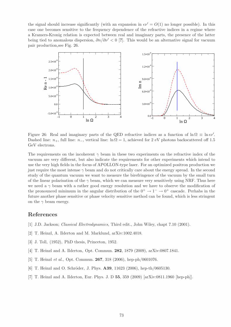
the signal should increase significantly (with an expansion in ǫν ′ = O(1) no longer possible). In thiscase one becomes sensitive to the frequency dependence of the refractive indices in a regime wherea Kramers-Kronig relation is expected between real and imaginary parts, the presence of the latterbeing tied to anomalous dispersion, ∂n/∂ν ′ < 0 [?]. This would be an alternative signal for vacuumpair production,see Fig. 26.
-1 0 1 2 3 4ln Ω
-5.0×10⁻⁹
0.0
5.0×10⁻⁹
1.0×10⁻⁸
1.5×10⁻⁸
2.0×10⁻⁸
2.5×10⁻⁸
Re
n -
1
-1 0 1 2 3 4ln Ω
0.0
3.0×10⁻⁹
6.0×10⁻⁹
9.0×10⁻⁹
1.2×10⁻⁸
1.5×10⁻⁸
Im n
Figure 26: Real and imaginary parts of the QED refractive indices as a function of ln Ω ≡ ln ǫν ′.Dashed line: n+, full line: n−, vertical line: ln Ω = 1, achieved for 2 eV photons backscattered off 1.5GeV electrons.
The requirements on the incoherent γ beam in these two experiments on the refractive index of thevacuum are very different, but also indicate the requirements for other experiments which intend touse the very high fields in the focus of APOLLON-type laser. For an optimized positron production wejust require the most intense γ beam and do not critically care about the energy spread. In the secondstudy of the quantum vacuum we want to measure the birefringence of the vacuum by the small turnof the linear polarisation of the γ beam, which we can measure very sensitively using NRF. Thus herewe need a γ beam with a rather good energy resolution and we have to observe the modification ofthe pronounced minimum in the angular distribution of the 0+ → 1− → 0+ cascade. Perhabs in thefuture another phase sensitive or phase velocity sensitive method can be found, which is less stringenton the γ beam energy.
References
[1] J.D. Jackson; Classical Electrodynamics, Third edit., John Wiley, chapt 7.10 (2001).
[2] T. Heinzl, A. Ilderton and M. Marklund, arXiv:1002.4018.
[3] J. Toll, (1952), PhD thesis, Princeton, 1952.
[4] T. Heinzl and A. Ilderton, Opt. Commun. 282, 1879 (2009), arXiv:0807.1841.
[5] T. Heinzl et al., Opt. Commun. 267, 318 (2006), hep-ph/0601076.
[6] T. Heinzl and O. Schroder, J. Phys. A39, 11623 (2006), hep-th/0605130.
[7] T. Heinzl and A. Ilderton, Eur. Phys. J. D 55, 359 (2009) [arXiv:0811.1960 [hep-ph]].
73
5.3.3 Cascades of e+e− Pairs and γ-Rays triggered bya Single Slow Electron in Strong Fields
H. Ruhl1, N. Elkina1 and A. Fedotov1
1 Department of Physics, LMU Munich, 80333 Munich (Germany)
Vacuum breakdown Field assisted vacuum breakdown is likely to be important at intensitiesenvisioned at ELI. Recently Bell and Kirk [1,2] prediced a prolific pair production at laser intensitiesapproaching 1024W/cm2 by analytic methods. Here we consider a scenario where a single slow electronis initially present in a very intense electromagnetic field. In the context of those strong external fieldsthe latter electron is capable of emitting photons at enhanced rates, which in turn seed e+e−-pairs.The process leads to a multiplication effect and sets in about two orders of magnitude in the externalfield earlier than the production of a pair from photons only. The simuations show that pair creationis overestimated by analytic models.
The quantum efficiency parameter In order to observe the emission of a photon in the contextof a strong electromagnetic field it is necessary to maximize the external electric field at the locationof an electron or positron. Calculations done by Nikishov and Ritus identify the quantum efficiencyparameter for the emission of radiation from charges
χe =e~
m3c4
√
− (Fµνpν)2 =
γ
Es
√
√
√
√
(
~E + ~v × ~B)2
−(
~v · ~E
c
)2
, (1.12)
where
γ =
√
1 +~p2
m2c2, ~v =
c~p√
m2c2 + ~p2, Es =
m2 c3
e ~= 1.32 · 1018 V
m(1.13)
that has to be as large as possible. The parameter χe can be calculated for simple situations neglectinghard photon emission. If a circularly polarized standing wave is assumed to be present at the positionof an electron, where ~B = 0 holds, the equations of motion of an electron initially at rest in the fieldof the latter are
d~p
dt= −e ~E , ~p(0) = 0 , (1.14)
where
~E(t) = E0
(
cos ωtsin ωt
)
. (1.15)
The solutions for ~p(t) is
~p(t) = −eE0
ω
(
sinωt1 − cos ωt
)
(1.16)
and for ~v(t)
~v(t) = − eE20
m ω γ(t)
(
sinωt1 − cos ωt
)
, (1.17)
where γ(t) is
γ(t) =
√
1 + 4 a2 sin2 ωt
2, a =
eE0
m ω c. (1.18)
74

0 0.5
1 1.5
2 2.5
3 3.5
4 4.5
5
0 2 4 6 8 10 12
ωt
χe(t
)
Figure 27: The parameter χe(t) for a circular polarized electric field at a = 1000 and ω = 1.88·1015 s−1.
Now χe(t) can be calculated to be
χe(t) =E0
Es
√
1 + 4 a2 sin2 ωt
2− a2 sin2 ωt
2=
a ~ ω
m c2
√
1 + 4 a2 sin4 ωt
2, (1.19)
where
~
m c2= 1.288 · 10−21 sec . (1.20)
Figure 27 shows χe(t) neglecting the emission of hard photons.
Hard photon emission and pair production If hard photon emission is included χe(t) has tobe computed numerically since the momentum of the emitting electron changes in the course of hardphoton emission. We make the following assumptions
~k =~p
p
ω
c, ~p
′
=~p
p
√
(
√
m2c2 + p2 − ~ ω
c
)2
− m2c2 , p > 0 , θ ≈ 1
2γ, (1.21)
where ~k is the photon wave vector, ~p′
is the post-emission electron vector, and θ is the angle betweenemitting electron and emitted photon. Figure 28 shows χe(t) with hard photon emission included.Due to hard photon emission the parameter χe(t) is essentially prevented from becoming large. Thered line in the figure shows the case without photon emission. The blue lines give χe(t) with photonemission included. Since pairs are generated at arbitrary phase of the external field (blue lines at latertimes) their quantum efficiency parameters χe(t) can become very large (be above the red line). Asimilar parameter holds for the production of a e+e−-pair from a photon
χγ =e~
2
m3c4
√
− (Fµνkν)2 =~ω
mc2
1
Es
√
√
√
√
(
~E +c~k
k0× ~B
)2
−(
~k · ~E
k0
)2
, (1.22)
where k0 = ω/c and ~k is obtained from Eqn. (1.21).
75

Figure 28: The parameter χe(t) from numerical computation including hard photon emission at a =3000 and ω = 1015 s−1.
Transition rates in strong external fields The total transition rate for photon emission in thelimit of χe(t) ≫ 1 is given by
Wγ(t) ≈ α m2 c4
~ ǫ(t)χ
2
3e (t) =
αm c2
~
√
1 + 4 a2 sin2 ωt2
(
a ~ ω
m c2
√
1 + 4 a2 sin4 ωt
2
)2
3
. (1.23)
The transition rate for photon emission neglecting hard photon emission at a = 1000 and ω =1.88 · 1015 s−1 is plotted in Figs. 29 and 30. The total transition rate for pair creation in the limit ofχγ(t) ≫ 1 is given by
We+e−(t) ≈ α m2 c4
~ ǫ(t)χ
2
3γ (t) . (1.24)
The pair creation rates have to be computed numerically. However, at large electron energies they areof a magnitude comparable to hard photon emission.
Time and length scales There are a few important time and length scales connected with QED-cascading. The formation length and time scales at a = 1000 and ω = 1.88 · 1015 s−1 are
lcr ≈ m c2
eE0=
c
aω≈ 1.59 · 10−10 m , tcr ≈ lcr
c=
1
aω≈ 5.32 · 10−19 s . (1.25)
Those scales represent thresholds that have to be overcome before the vacuum can be unstable. Theytypically cannot be resolved on a computer and are dealt with within analytical theory. Other usefultime and length scales are those on which χe(t) ≈ 1 is reached. They represent the time and lengthscales on which the electron accelerates and hence can enlarge χe(t). Yet other length and time scalesare given by
lfree =c
tfree,
∫ tfree
0dτ W tot
γ,e+e−(τ) ≈ 1 . (1.26)
Those are the time and length scales between two events.
76

0 1 2 3 4 5 6 7 8 9
10 11
6.24 6.26 6.28 6.3 6.32 6.34
ωt
Wto
tγ
(t)/
1017s−
1
Figure 29: The total transition rate W totγ (t) for a circular polarized electric field at a = 1000 and
ω = 1.88 · 1015 s−1.
0.2
0.3
0.4
0.5
0.6
0.7
0.8
0.9
1 2 3 4 5 6
ωt
Wto
tγ
(t)/
1017s−
1
Figure 30: The total transition rate W totγ (t) for a circular polarized electric field at a = 1000 and
ω = 1.88 · 1015 s−1.
77

Transport equations Neglecting higher order effects as annihilation of pairs and classical radia-tion reaction effects the system consisting of electrons, positrons, and radiation can be described bytransport equations of the following kind
(
∂t + ~v · ∂~x − e(
~E + ~v × ~B)
· ∂~p
)
f±(~x, ~p, t) (1.27)
=
∫
ω>ω0
d3k W~E, ~B
γ (~k, ~p + ~k) f±(~x, ~p + ~k, t) − f±(~x, ~p, t)
∫
d3kω>ω0W
~E, ~Bγ (~k, ~p)
+
∫
ω>ω0
d3k W~E, ~B
e+e−(~k, ~p) fγ(~x,~k, t)
(
∂t +∂ω
∂~k· ∂~x
)
fγ(~x,~k, t) (1.28)
=
∫
d3p W~E, ~B
γ (~k, ~p) [f+(~x, ~p, t) + f−(~x, ~p, t)]
−fγ(~x,~k, t)
∫
d3p W~E, ~B
e+e−(~k, ~p) ,
which for ω < ω0 have to be coupled to Maxwell’s equations with the current
~j(~x, t) = e
∫
d3p~v [f+(~x, ~p, t) − f−(~x, ~p, t)] . (1.29)
It has to be made sure that radiation contained in ~E, ~B, and fγ will not lead to double counting ofradiation, hence the ω < ω0 threshold.
Pair production Simple analytical estimates yield
µ I[
Wcm2
]
N±
0.1 3 · 1023 non
1.0 3 · 1025 ≈ 104
2.0 1.2 · 1026 ≈ 1010
where the production rates depends on a parameter µ = E0/αEs. The simulations, however, showthat pair creation is over-estimated by the analytical model but still strong. We obtain a lineargrowth with time for various amplitudes a. Figure 31 shows the distribution of hard photons (blackarrows), electrons (red lines), and positrons (blue lines) after one full cycle of the external fields.The yellow dots indicate pair creation events. Figure 32 shows a logarithmic plot of the number ofelectrons and positrons as a function of time. The growth rate that can be infered is Γ ≈ 1016 s−1 fora = 3000 and ω = 1015 s−1. In conclusion, a novel numerical code has been presented that is capable ofcalculating the effects of vacuum instability. Starting from a single initial electron a cascade consistingof radiation, electrons and positrons is obtained with a growth rate of about Γ ≈ 1016 s−1 at a = 3000and ω = 1015 s−1. With growing a the laser energy distributed over electrons, positrons and hardphotons shifts. At large a radiation is suppressed in favor of matter.Injecting low energy electrons into the laser focus the cascades of higher energy electrons can bemeasured with the planned magnetic spectrometers and the theoretical predictions can be tested indetail.
References
[1] A. R. Bell and J. G. Kirk, Phys. Rev. Lett. 101, 200403 (2008);
[2] J. G. Kirk, A. R. Bell and I. Arka, Plasma Phys. Ontrol. Fusion 51, 085008 (2009).
78

Figure 31: The γe+e−-cascade for a circular polarized electric field at a = 3000 and ω = 1015 s−1.
Figure 32: The total number of electrons and positrons as a function of time for a circular polarizedelectric field at a = 3000 and ω = 1015 s−1.
79

5.3.4 Compton Scattering and Radiation Reactionof a Single Electron at High Intensities
T. Heinzl1, N.M. Naumova2 D. Habs3, and P.G. Thirolf31 University of Plymouth, Plymouth PL4 8AA, (UK),2 Laboratoire d’Optique Appliquee, UMR 7639 ENSTA, Palaiseau (France)3 Ludwig Maximilians University, Munich (Germany)
The process in question is the collision of an electron and a high intensity laser beam, such that aphoton γ ′ is scattered out of the beam. The relevant physical parameters are the laser frequency, ω,the electron energy measured in terms of their gamma factor, γ = Eel/m, and the dimensionless laseramplitude,
a0 =eE
mω. (1.30)
This represents the energy gain of an electron (charge −e, mass m) traversing a laser wavelength,λ = λ/2π = 1/ω, in an r.m.s. field E, in units of the electron rest energy, m (employing natural units,~ = 1 = c). Thus, when a0 is of order unity, the electron quiver motion becomes relativistic. It isuseful to rewrite (1.30) in terms of laser intensity I and wavelength λ,
a0 = 6 × 10²√
I/I24 λ/µm , (1.31)
where I24 ≡ 1024 W/cm2 is the intensity envisioned for the Romanian ELI subproject.Using the theory of quantum electrodynamics (QED) nonlinear Compton scattering has been analysedalready in the early sixties (soon after the invention of the laser) treating the laser field as an infiniteplane wave [2–5]. In this case, one can utilise an exact solution of the Dirac equation going backto Volkov which provides a quantum description of the quivering electron. In QED jargon, such an
e−
e−
γ
= ... + ...
n γL
e−
e−
γ
+ ...
Figure 33: Feynman diagrams for nonlinear Compton scattering.
electron is said to be ‘dressed’ by the background field and may be depicted as shown on the left-handside of Fig. 33 which, when expanded in the number of laser photons involved, becomes a sum ofdiagrams of the type shown on the right-hand side representing the processes
e + nγL → e′ + γ ′ . (1.32)
Here, the electron absorbs an arbitrary number n of laser photons γL of energy ω ≃ 1 eV beforeemitting a single photon γ ′ of energy ω′.Note that the tree-level diagrams involved have a classical limit which is a good description of theprocess when the electron mass m is the dominant energy scale [6]. This classical limit is referred toas Thomson scattering. It is valid as long as the following frame independent inequality holds,
ν0 ≡ k · pm2
≪ 1 , (1.33)
where k and p are the asymptotic four-momenta of laser photons and electrons, respectively. Inthe electron rest frame one has ν0 = ~ω0/mc2 (temporarily reinstating ~ and c). In terms of lab
80

quantities, this implies γ ≪ m/2ω ≃ 105 . . . 106, in agreement with the folklore that the Thomsonscattering is the a low-energy limit. With an electron linac producing electrons in the 600 MeV rangeγ will be of order 103 so that one is starting to move away from the Thomson (towards the Compton)regime. In any case, it is important to stress that, unlike say pair creation, the processes (1.32)are not suppressed by any threshold effects. Thus, one can study intensity effects at arbitrarily lowcentre-of-mass energies both for photons and electrons. This is quite a unique feature of nonlinearThomson/Compton scattering and singles out this process from a particle physics point of view.
100
101
102
103
0
0.2
0.4
0.6
0.8
1
1.2
1.4
x 10−3
ω′ (eV)
dW /d
ω′ (
arb.
uni
ts)
Figure 34: Nonlinear Compton spectrum for ELI parameters (intensity parameter a0 = 500, laserenergy ω = 1.5 eV and electron energy Eel = 1 GeV).
In Fig. 34 we show the photon emission rates as a function of the emitted photon frequency, ω′. Thecentral peak corresponds to the first harmonic (n = 1) located at scattered frequency ω′
1 ≃ 4γ2ω/a20 ≃
102 eV. Note that this is substantially red-shifted from the linear Compton edge, 4γ2ω ≃ 25 MeV.The side maxima to the right of the global maximum correspond to higher harmonics, ω′
n ≃ nω′1. In
the lab frame, for the parameter values chosen, there is still some energy transfer from electrons tothe scattered photons, hence the blue-shift ω → ω′
n > ω. In an astrophysical context such a process isreferred to as ‘inverse Compton scattering’. This is to be contrasted with ‘normal’ Compton scattering(Compton’s original experiment) where the electrons are at rest in the lab and one observes a red-shiftof the photon frequency, ω′ < ω. The inverse Thomson/Compton up-shift is now being routinely usedto create γ beams, for instance at Lawrence Livermore National Laboratory, where the T-Rex facilityis the world’s highest peak brightness MeV γ source.The details of nonlinear Compton scattering have recently been reviewed in [7] with an emphasis onlab frame signatures, treating the laser as an infinite plane wave. In this case the red-shift of the linearCompton edge may be understood in terms of the electron mass shift,
m∗ = m√
1 + a20 , (1.34)
which may be interpreted as being due to an averaging over the electron quiver motion. This addsan intensity dependent, longitudinal contribution to the electron four-momentum p resulting in thequasi-momentum
q = p +a2
0m2
2k · p k . (1.35)
Using the fact the photons are massless (k2 = 0), it is easy to see that q2 = m2∗. Thus, as the
81

electron ‘gains weight’ (m → m∗) it will recoil less, reducing the energy transfer to the final statephoton, hence the red-shift in the maximum photon energy1, see Fig. 34. The associated spectra arecharacterised by momentum conservation using electron quasi-momenta, i.e. q + nk = q′ + k′, withthe momenta in one-to-one correspondence with the particles of (1.32). Among other things, thisconservation law determines the spectral ranges, in particular its minimum and maximum values, or‘Compton edges’ [7].In the lab frame there is an interesting interplay between laser intensity and electron energy. We haveseen that backscattering off high-energy electrons (γ ≫ 1) produces a blue-shift (‘inverse’ Compton).On the other hand, high intensity (a0 ≫ 1) produces a red-shift, hence works in the opposite direction.It turns out that there is exact balance in the centre-of-mass frame of the Volkov electrons and then laser photons, that is when 4γ2/a2
0 ≃ 1 [7]. This can obviously be achieved by fine-tuning γ anda0: for 1 GeV electrons the associated a0 is about 2γ ≃ 4 × 10³. Hence, for a0 of this order or largerone expects an overall red-shift, ω′ < ω, as the Volkov electron has become so heavy that it appearsalmost ‘static’ from the photons’ point of view. On the other hand, assuming the ELI value a0 ≃ 500,one would just need 100 MeV electrons to test this interesting spectral regime. Fig. 35 gives an ideaof how sensitively the spectra depend on the magnitude of a0 choosing γ = 100 so that the criticala0 ≃ 200.As stated above, the critical value of a0 ≃ 2γ defines an intensity dependent centre-of-mass framewhere the total momentum vanishes,
~P ≡ ~q + n~k = ~p +
(
a20m
2
2k · p + n
)
~k = 0 . (1.36)
As k · p > 0 this obviously requires that ~p and ~k are anti-parallel (head-on collision). Again, note theexplicit dependence on the laser strength parameter a0.It is important to stress that the electron mass shift, though predicted long ago [5, 8], has neverbeen directly confirmed in an experiment as intensities have been too small until recently. NonlinearCompton scattering (1.32) has been observed and analysed in the SLAC E-144 experiment [9] using47 GeV electrons from the SLAC beam and a Terawatt laser with a0 ≃ 0.4. This was a high energy(γ ≃ 105) and low intensity (a0 < 1) experiment (hence deep in the ‘inverse’ Compton regime). Photonspectra were not recorded and hence no red-shift was observed [9]. ELI should rectify this omissionby recording detailed photon spectra in the complementary regime of intermediate energies and highintensities (γ ≃ a0 ≃ 103), thus exploring this uncharted region of the standard model for the firsttime.The considerations above are valid for an infinite plane wave. This should be a good approximation aslong as the pulse duration T is large compared to the laser period, T ≫ 2π/ω. In this case the electron‘sees’ sufficiently many cycles to be dragged along with the pulse which effectively increases its mass,m → m∗. For ultra-short pulses of a few cycles this picture has to be modified [6,10]. The spectra willthen be dominated by finite size effects in both space and time. Qualitatively, the following featurescan be seen to arise. In an infinite plane wave, the Compton edge becomes red-shifted such that thephoton emission signal above ω′
1 = 4γ2ω/a20 is entirely due to higher harmonics (n > 1) and strongly
suppressed (see Fig. 34). For a short pulse, the gap between this nonlinear and the linear Comptonedge (ω′ = 4γ2ω) gets ‘populated’ with an oscillatory signal (substructure) which, however, remainssuppressed compared to the principal maximum at the nonlinear edge [6]. Thus, for large a0, oneshould not expect a substantial yield of frequency up-shifted photons.This extreme sensitivity to beam characteristics may, nevertheless, be turned into a bonus by usingnonlinear Compton/Thomson scattering as a diagnostic tool both for the electron beam [11] and thelaser [6]. In particular, it has been suggested to gain information on the carrier phase of the pulse inthis way [12].As pointed out by McDonald [13] the QED (hence quantum) analysis of Compton scattering shouldcontain corrections to Thomson scattering due to radiative reaction. The basic reason is energymomentum conservation which in a scattering process equates the total four-momenta of incoming
1Therefore, if one is interested in a large energy up-shift, e.g. to produce γ rays, one should rather use low intensitybeams (a0 < 1) to scatter off from the electrons.
82
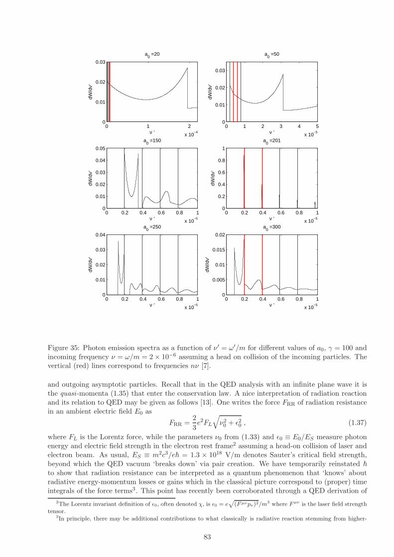
0 1 2
x 10−4
0
0.01
0.02
0.03
a0 =20
ν ‘
dW/d
ν‘
0 1 2 3 4 5
x 10−5
0
0.01
0.02
0.03
a0 =50
ν ‘
dW/d
ν‘0 0.2 0.4 0.6 0.8 1
x 10−5
0
0.01
0.02
0.03
0.04
0.05
a0 =150
ν ‘
dW/d
ν‘
0 0.2 0.4 0.6 0.8 1
x 10−5
0
0.2
0.4
0.6
0.8
1
a0 =201
ν ‘dW
/dν‘
0 0.2 0.4 0.6 0.8 1
x 10−5
0
0.01
0.02
0.03
0.04
a0 =250
ν ‘
dW/d
ν‘
0 0.2 0.4 0.6 0.8 1
x 10−5
0
0.005
0.01
0.015
0.02
a0 =300
ν ‘
dW/d
ν‘
Figure 35: Photon emission spectra as a function of ν ′ = ω′/m for different values of a0, γ = 100 andincoming frequency ν = ω/m = 2 × 10⁻⁶ assuming a head on collision of the incoming particles. Thevertical (red) lines correspond to frequencies nν [7].
and outgoing asymptotic particles. Recall that in the QED analysis with an infinite plane wave it isthe quasi-momenta (1.35) that enter the conservation law. A nice interpretation of radiation reactionand its relation to QED may be given as follows [13]. One writes the force FRR of radiation resistancein an ambient electric field E0 as
FRR =2
3e2FL
√
ν20 + ǫ2
0 , (1.37)
where FL is the Lorentz force, while the parameters ν0 from (1.33) and ǫ0 ≡ E0/ES measure photonenergy and electric field strength in the electron rest frame2 assuming a head-on collision of laser andelectron beam. As usual, ES ≡ m2c3/e~ = 1.3 × 10¹⁸ V/m denotes Sauter’s critical field strength,beyond which the QED vacuum ‘breaks down’ via pair creation. We have temporarily reinstated ~
to show that radiation resistance can be interpreted as a quantum phenomenon that ‘knows’ aboutradiative energy-momentum losses or gains which in the classical picture correspond to (proper) timeintegrals of the force terms3. This point has recently been corroborated through a QED derivation of
2The Lorentz invariant definition of ǫ0, often denoted χ, is ǫ0 = ep
(F µνpν)2/m3 where F µν is the laser field strengthtensor.
3In principle, there may be additional contributions to what classically is radiative reaction stemming from higher-
83

a modified Lorentz-Abraham-Dirac equation [1, 14] based on the original QED analysis [2].Continuing with our analysis of (1.37) we note that backreaction becomes important when either ν0
or ǫ0 become of order unity. Let us discuss both parameters one after the other. We have already seen(in Footnote 1) that ν0 ≪ 1 implies that we are in the Thomson rather than Compton regime. For ELIparameters one finds ν0 = γ(1 + β)ν ≃ 10−2 so quantum corrections associated with electron recoilshould be at the percent level. On the other hand, one calculates ǫ0 = γ(1 + β)E/ES = O(1) uponassuming an r.m.s. lab field of magnitude E ≃ 10−3ES . Thus, when radiative reaction is large due tolarge ǫ0, then, in its own rest frame, the electron sees an electric field of the order of Sauter’s criticalfield! Accordingly, with the present ELI parameter values we are right at the pair production thresholdES or, for optimal values, even slightly above. One may thus expect to see positrons generated bythe particular combination of high intensity for the laser photons and sufficiently high energy forthe electrons (γ ≃ a0 ≫ 1). This may even lead to prolific pair creation via cascading processes‘maintained’ by subsequent repeated laser acceleration of the produced pairs [15–17].There is, however, a caveat here: the SLAC experiment has shown that the energy threshold for paircreation becomes intensity dependent, s > 4m2
∗, where s is the usual invariant defining the total energyin the centre-of-mass frame,
√s. This increase is due to the fact that pairs with effective mass m∗
need to be produced which, in turn, suggests that the critical field increases as well, ES → E∗S ≡ m2
∗/e.Again, this may depend on pulse duration and possible other finite size effects which makes it all themore important to actually probe the details of the mass shift experimentally.After all, it is this very mass shift which determines the size of the radiative reaction. Upon rewriting(1.37) as
FRR/FL =2
3e2ν0
√
1 + a20 , (1.38)
it becomes manifestly proportional to the mass scaling factor, cf. (1.34), and, reassuringly, yields thesame numerical value as (1.37). We thus can conclude that it is indeed the appearance of a0 in (1.38),as well as in the quasi-momenta q and q′ and the associated conservation law, which signals backre-action. That’s why the analysis of Thomson scattering in [18] using the purely classical language ofradiation reaction is nothing but a reinterpretation of the intensity dependent centre-of-mass dynamicscharacterised by (1.36) and depicted in Fig. 35. The connection is provided by (1.38), the right-handside of which is just the radiation reaction parameter R defined in [18], multiplied by a0.The scattering between laser photons and relativistic electrons is governed by three dimensionless,Lorentz invariant parameters, which can be conveniently written as
ν0 = ω0/m = 10−5 Eel/MeV , (1.39)
a0 =eE0
ω0m= 6 × 10²
√
I/I24 λ/µm , (1.40)
ǫ0 =E0
ES= 6 × 10⁻³
√
I/I24 Eel/MeV . (1.41)
The last identity, adapted from [1], is plotted in Fig. 36. The subscripts “0” refer to the electronrest frame with the lab frame electric field being given by E = γ(1 − β)E0 and likewise for the laserfrequency ω.It is important to note that the parameters (1.39–1.41) are not independent as ǫ0 = a0ν0. However, allthree are useful as they characterise different physics. When ν0 = O(1) we are in the genuine quantum(Compton rather than Thomson) regime. As also stated there, a0 = O(1) implies that the electronquiver motion in the laser becomes relativistic. Finally, when ǫ0 = O(1) the electron ‘sees’ an electricfield of the order of the critical one in its rest frame which implies the onset of pair creation. Theauthors of [1] have fittingly dubbed the electric fields in the last two cases as “relativistically strong”and “QED strong”, respectively.According to a recent paper by Sokolov et al., [1], for I = 1024W/cm2 and a 1 GeV electron beam,photons of ≈15% of electron beam energy can be generated efficiently for values of ǫ0 in the range
order radiative corrections (final state interactions and loop diagrams). These are obviously not included in the lowestorder diagrams of Fig. 33. Not much is known about such corrections and we do not include them in this discussion.
84

Figure 36: Dependence of the parameter ǫ0 from (1.41) on the electron energy Eel and the intensityI of the counter-propagating laser beam. Full line: I = I24 = 1024 W/cm2. Dashed line: I = 1023
W/cm2.
between 1 and 10. It means that ≈ 150 MeV photons are expected for a 1 GeV electron beam. It isnecessary to note that ≈ 100 MeV electrons are easily generated during the interaction of such intenselaser pulses with plasmas, what leads to the production of ≈ 15 MeV photons.
References
[1] I.V. Sokolov, J.A. Nees, V.P. Yanovsky, N.M. Naumova, and G.A. Mourou, Emission and its back-reaction accompanying electron motion in relativistically strong and QED-strong pulsed laser fields,Phys. Rev. E 81 (2010);arXiv:1003.0806v1.
[2] A. I. Nikishov and V. I. Ritus, Zh. Eksp. Teor. Fiz. 46 (1963) 776–796. [Sov. Phys. JETP 19,529 (1964)]; A. I. Nikishov and V. I. Ritus, Zh. Eksp. Teor. Fiz. 46 (1964) 1768–1781. [Sov. Phys.JETP 19, 1191 (1964)].
[3] N. B. Narozhnyi, A. Nikishov, and V. Ritus, Zh. Eksp. Teor. Fiz. 47 (1964) 930. [Sov. Phys. JETP20, 622 (1965)];
[4] I. I. Goldman, Phys. Lett. 8, 103 (1964).
[5] L. S. Brown and T. W. B. Kibble, Phys. Rev. 133, A705 (1964).
[6] T. Heinzl, D. Seipt and B. Kampfer, Phys. Rev. A 81, 022125 (2010).
[7] C. Harvey, T. Heinzl and A. Ilderton, Phys. Rev. A 79, 063407 (2009) [arXiv:0903.4151 [hep-ph]].
[8] N. Sengupta, Bull. Math. Soc. (Calcutta) 44 (1952) 175–180.
[9] C. Bamber et al., Phys. Rev. D 60, 092004 (1999).
[10] G. Krafft, Phys. Rev. Lett. 92, 204802 (2004).
[11] W. Leemans et al., Phys. Rev. Lett. 77, 4182 (1996).
[12] F. Mackenroth, A. Di Piazza and C. H. Keitel, arXiv:1001.3614 [Unknown].
85

[13] K.T. McDonald, Limits on the Applicability of Classical Electromagnetic Fields as Inferred fromthe Radiation Reaction, unpublished preprint, available from http://www.hep.princeton.edu / mc-donald/examples/radreact.pdf.
[14] I.V. Sokolov et al., arxiv:0910.4268 [physics.plasm-ph].
[15] A. R. Bell and J. G. Kirk, Phys. Rev. Lett. 101, 200403 (2008).
[16] J. G. Kirk, A. R. Bell and I. Arka, PPCF 51, 085008 (2009), arXiv:0905.0987 [hep-ph].
[17] A. Fedotov, N. Narozhny and G. Mourou, Report on the ELI Grand Challenges Meeting, ed.sG. Korn and P. Antici, Paris 2009.
[18] A. Di Piazza, K. Z. Hatsagortsyan and C. H. Keitel, Phys. Rev. Lett. 102, 254802 (2009)[arXiv:0810.1703 DOC-TYPE = PREPRINT [Unknown]].
[19] T. Heinzl., Journ. of Phys.: Conference Series 198 012005 (2009).
[20] T. Heinzl et al., arXiv:0911.1622v2[hep-ph] 14 Dec 2009
86

5.3.5 Nuclear Lifetime Measurements by Streaking ConversionElectrons with a Laser Field.
D. Habs1, M. Gross1 and P.G. Thirolf13 Ludwig Maximilians University, Munich (Germany)
Nuclear levels have lifetimes down to the zeptosecond range once one reaches excitation energiesbeyond the particle emission threshold, while nuclear levels have lifetimes longer than typically 10fs below the particle threshold [1]. We plan to study this drastic change in lifetime and predictedchanges in decay laws for the first time. We modulate the energy of emitted conversion electrons in aphase-locked laser field and carry over the technique used to measure as lifetimes of atomic levels [2]to nuclear systems. Only for heavier nuclei we will get sufficiently large conversion coefficients. Wewill follow the modulated energies of the accompanying conversion electrons of the particle decay. Weinduce the particle decay by the γ beam, which is locked to the APOLLON-type laser or the γ’s fromthe relativistiv mirror (project 4.4). Since we do not require the maximum laser fields, we may uselaser light from an earlier amplifier state, which is delivered with higher repetition rate like 10 Hz.We want to induce the particle decay with very short γ-pulses, where we hopefully reach times below1 as for the relativistic mirror. The emitted conversion electrons have energies, where the K bindingenergy is subtracted from the γ beam energy (typically 6-8 MeV). They can be observed in an electronspectrometer under angles where laser accelerated electrons from the target do not contribute.Fig. 37 shows some nuclear lifetimes as a function of the excitation energy above the ground state forE1 and M1 transitions. In comparison also typical atomic lifetimes as a function of level energy areshown. Until now only time integrated particle spectra have been measured and it was not possibleto measure the particle spectra as a function of the emission time. Typical particle emission times inthe range of 10−20 s are obtained from statistical model calculations for higher excitation energies. Ifit were possible to follow the emission spectra as a function of time, e.g. a much better understandingof dissipation and damping processes in the energy region of overlapping resonances above ∼15 MeVexcitation energy could be obtained.
Figure 37: Correlation between nuclear lifetime and energy. The curve in green corresponds to atomiclevels with oscillator strength f=1, the red curves represent single particle estimates for nuclear E1 andM1 γ transitions, while the blue line denotes the limit given by the uncertainty relation for a single-cycle laser pulse. The dashed black lines indicate lifetimes of nuclear levels after particle emission fordifferent mass numbers A.
Experimental access to these ultrashort sub-attosecond lifetimes can be gained by exploiting theproduction technique for brilliant photon beams, where laser pulses are Compton-backscattered from arelativistic electron mirror, thus resulting in an energy boost by a factor of 4 γ2, while the corresponding
87

pulse duration is reduced by a factor 1/(4γ2). For a single cycle pulse the energy versus time relationwould be described by the uncertainty principle. This demonstrates that excitations with gγ pulsesmuch shorter than the expected lifetimes are possible. Though many experimental methods have beendeveloped in different time ranges for different decay modes, transfering the well-established streakingtechnique of atomic physics to the regime of even shorter lifetimes in nuclear physics will enableto disentangle different channels of nuclear decay processes, where complex energy spectra could befollowed as a function of time.
Properties of the decay in time of the compound nucleus Ultrashort light pulses offer thepossibility to study photonuclear reactions up to 10 or 15 MeV from a different and completely newperspective. The band width ∆E = ~/∆t defined by the length (in time) ∆t of the pulse may be largecompared to the mean spacing d between adjacent levels of the same spin and parity. For medium-weight and heavy nuclei, d is typically 100 keV near the ground state and decreases exponentially withexcitation energy, so that typically d ∼ 10eV at the neutron threshold, i.e. there are about 106 levelsabove the ground state. Below the neutron threshold, the average decay width Γ of nuclear levels isdue to γ emission and has typical values of 10 meV. Right above the neutron threshold, particle decayincreases Γ to typical values of about 1 eV. From here on Γ increases monotonically with excitationenergy, until it reaches typical values of 50 or 100 keV (corresponding to a lifetime of 10−21 s) at theupper end of the energy interval here considered. Until now, photonuclear reactions were investigatedwith continuous beams of fairly poor energy resolution (measured in terms of the values of Γ and ddiscussed above) and have yielded only gross features of nuclear excitation functions, with the exceptionof the study of individual levels in the ground state domain. In particular spectroscopic propertiesof levels in the energy range between several 100 keV of excitation energy and the neutron thresholdare unknown. Neutron time-of-flight spectroscopy has offered a window to study spacing distributionsand other statistical properties of levels (i.e. neutron resonances) right above the neutron threshold.The outstanding feature of that gross structure is the emergence of giant resonances, especially thegiant dipole resonance, that were investigated in considerable detail.With a band width ∆E > d, several or even many nuclear states will be simultaneously excited.In that case, meaningful theoretical statements can be made only if ∆E >> d or, if Γ >> d, for∆E >> Γ. Then the decay in time of the excited nucleus is determined by the Fourier transform ofthe photonuclear autocorrelation function. With Sab(E) being the scattering amplitude leading fromthe incident photon channel to the final channel b, that function is defined as
Sab =
∫
|g(E)|2Sab(E + 1/2ǫ) · S∗ab(E − 1/2ǫ). (1.42)
Here |g(E)|2 describes the distribution in energy of the photon intensity and is centered at energy E0
with width ∆E. The autocorrelation function is a running average over energy of the two scatteringamplitudes with arguments separated by the energy ǫ. For the energy average to be representative, wemust have ∆E >> d,Γ. At the same time, ∆E should be small in comparison with the characteristicenergy scale of gross features of photonuclear excitations. For the giant dipole resonance that isthe resonance width with typical values around several MeV. The numbers given above for d and Γthen define the desirable band width for short light pulses. It is given by ∆E = Nmax(d,Γ), where Ndetermines the relative statistical accuracy 1/
√N of the energy average. The spectroscopic data taken
with neutron time-of-flight spectroscopy are consistent with a random matrix description and suggestthat the compound nucleus is chaotic. It is probable that this feature prevails at lower excitationenergies. The hallmark of that description is a non-exponential decay in time of the compoundnucleus when few channels are open. Only for many open channels is the expected exponential decayattained (mean lifetimes are always defined in terms of the values of Γ that pertains to the energyinterval of interest). Measurements on the decay in time of nuclei excited by short light pulses couldconfirm this theoretical expectation. In particular such data could cast light on hitherto unexploredproperties of excited nuclear states below the neutron threshold.H.A. Weidenmuller et al., [5] are studying the decay of such compound nuclear resonances withinrandom-matrix theory [3] and find an exponential decay below the particle threshold, while theypredict an exponential decay folded by a power law above the particle threshold. Weidenmuller et al.
88

state that such measurements “comprise information on amplitude correlations in compound nucleusresonances, which cannot be obtained from other observables and that they would establish a newunambigous test of random-matrix theory for nuclear physics”.
Streaking of electrons Experimental access to sub-attosecond nuclear lifetimes can be expectedfrom an adaptation of the well-established streaking technique of atomic physics [1,2] to decay processesin excited nuclei. Nuclear levels below the particle emission threshold (∼ 6-8 MeV) not only decayby γ emission but also are accompanied by prompt conversion electrons with a fraction given by theconversion coefficient. The dominant peaks in the conversion electron spectrum are the K-conversionlines. Now we excite a level of a stable nucleus with a γ beam of suitable energy. In parallel wesuperimpose a laser field to the nucleus with a tunable delay between the photonuclear excitationand the streaking field for the conversion electron. The energy modulation of the conversion electronshould be in the range of 5 keV, requiring only moderate laser intensities of about 1014W/cm2. With amagnetic transport and filter system (’Mini-Orange’ spectrometer [3]) for conversion electrons we canchoose the transmission curve to select a narrow range of the conversion electron spectrum with highefficiency, while fully suppressing all electrons being directly accelerated from atomic shells. By varyingthe delay of the streaking field, lifetimes in the range of 1-100 fs can be measured. For the releaseof the conversion electrons we need γ beams of 10 keV - 5 MeV. Metallized tapes with stable targetnuclei would be ideal targets. The measurements would allow to determine the spins and parities ofthe excited levels. From the transition matrix elements many properties of their wave functions couldbe deduced.
References
[1] D. Habs et al., Eur. Phys. J. D 55, 279 (2009).
[2] E. Goulielmakis et al., Science 317, 769 (2007).
[3] H.A. Weidenmuller and R. Dietz; Photonuclear Reactions induced by Intense Short Laser Pulses,to be published (2010).
[4] H.A. Weidenmuller and G.E. Mitchell, Rev. Mod. Phys. 81, 539 (2009).
[5] J. Itatani et al., Phys. Rev. Lett. 88 (2002) 173903.
[6] R. Kienberger et al., Nature 427 (2004) 817.
[7] J. v. Klinken and K. Wisshak, Nucl. Instr. Meth. 98 (1972) 1.
89

5.4 Stand-alone γ/e− Facility for Nuclear Spectroscopy
5.4.1 Measuring Narrow Doorway States, embedded in Regions of High Level Densityin the First Nuclear Minimum, which are identified by specific(γ, f), (γ, α), (γ, p), (γ, n) Reactions and allow to map out theNuclear Potential Landscape
D. Habs1, M. Gross1, P.G. Thirolf1, A. Krasznahorkay2 and L. Csige2
1 Ludwig Maximilians University, Munich (Germany)3 MTA, ATOMKI, Debrecen (Hungary)
We want to make use of the unique high resolution of the γ beam to selectively identify doorway stateswith a small damping width via the (γ, x) reaction. A prototype example are states in the secondor third potential minimum of actinide nuclei, which due to their tunneling through the inner barriershow a small damping width. These transmission resonances can be uniquely identified by their fissiondecay. Due to the high level density in the first minimum, there are always states in the first minimumwhich completely mix with the states in the 2. and 3. minimum and can be nicely excited via the γbeam. This concept of weakly coupled doorway states in fission can be carried over to p,n or α decays,where strongly deformed halo states again are particle unstable and we can identify them as rathersharp resonances in photonuclear reactions. We prefer to use odd target nuclei, because then we canpopulate several members of a rotational band with E1,M1 or E2 transitions.The present photon energy resolution of the HIγS facility at 6-8 MeV with 300 keV does not allowto identify these resonances, while a few keV are equivalent to the the resolution of particle-inducedreactions, where we identified such resonances [16]. In this way vibrational and rotational bands inthe second and third minimum can be identified [2]. From the rotational bands the moments of inertiacan be determined for the states in the different minima.We plan to employ multi-layer actinide targets, which allow to measure the fission fragment angulardistributions for rather thick overall targets. From the rotational and vibrational states the potentiallandscape of the nuclei can de deduced. At higher excitation energies a reasonable transmissionthrough the barrier exists and good yields can be expected. The spin and parity selectivity of the γexcitation is important. Also the damping width is an important parameter.
References
[1] P.G. Thirolf and D. Habs; Prog. in Part. and Nucl. Phys. 49, 325 (2002).
[2] M. Hunyadi et al., Phys. Lett. B 505 (2001) 27.
90

5.4.2 Precision Tests of Fluctuating Quantities in Nuclear Physics of Highly ExcitedNuclear Levels in Comparison to Random-Matrix-Theory and Quantum Chaos
D. Habs1, P.G. Thirolf1 , H.A. Weidenmuller2, B. Dietz3 and N. Pietralla2
1 Ludwig Maximilians University, Munich (Germany),2 Max-Planck Institut fur Kernphysik, Heidelberg (Germany),3 Institut fur Kernphysik, TU Darmstadt, Darmstadt (Germany)
A very detailed theory of highly excited compound nuclear states has been developed over the last 70years. It started with the compound nucleus picture of Bohr [1], where a nucleon collides with a nucleusand shares its energy with many nucleons and after many collisions the energy is concentrated again ina nucleon, which then is reemitted. This started the random-matrix theory by Wigner and Dyson [2]and finally led to the recent reviews on random matrices and chaos in nuclear physics [3, 4]. Thetheory represents a prototype for quantum chaos and leads to many generic predictions for fluctuatingquantities, like Porter-Thomas distributions for decay widths or nearest-neighbor-spacing (NNS) leveldistributions of the Gaussian Orthogonal Ensemble (GOE).Until now only smaller ensembles of quantities have been studied experimentally and seem to confirmthis theory. Here we want to perform precision measurements for levels above the particle thresholdwith the new intense, brilliant γ facility. One example are precise measurements of the energy levelsand their strength of (γ, n) resonances via a longer neutron flight path setup (≈100m). Here the highintensity of the γ beam, the very precise start signal (3 ps), the larger Breit-Wigner cross section andthe good band width of the γ beam allow precision measurements with several orders of magnitudelarger ensembles than obtained in earlier measurements.Thus we can test the generic predictions and perhaps additional refinements become necessary. E.g.deviations from the GOE description are expected when the spreading time or equilibration timebecomes comparable to the compound nucleus decay time [4]. At the same time many new predictionsare being developped in much more detail within random-matrix theory and they can be tested inhigh resolution experiments in the energy or time domain.The former studies of the double excitation of the giant dipole resonance [6, 7] can be regarded as afirst prototype of new pump-probe experiments with γ beams, exploring the interference of differentamplitudes of states, populated by damping into other compound states and then excited a secondtime. If the expected higher flux for γ beams can be realized with the relativistic mirror approach,such pump-probe experiments become possible for the given Breit-Wigner resonance cross sectionsand more detailed time dependent studies of developments in quantum chaos.Also the decay of these compound nucleur states in time frequently are not simple exponentials, butshow power law components [5,8]. Here new precision measurements in the as and zs time range (seeProject 5.4) will allow to test a rich new world of predictable decay patterns.A fourth class of experiments may explore the violation of symmetries and invariances [4]. An exampleare parity violating amplitudes in E1/M1 mixing (see also project 6.4), where close lying parity dou-blets will increase these amplitudes with increasing excitation energy, because more levels of oppositeparity move closer and closer together.Thus these precision experiments will lead to a deeper understanding of higher-lying nuclear levels andquantum chaos. We will be able to predict the strong component of the many very weak, unobservabletransitions of the pygmy dipole resonance more accurately via the random matrix theory of thisfluctation strength and obtain better predictions for the element production in astrophysics.The measurement of the (γ,n) resonances also can have a large impact on the improved operation ofa future phase of the γ beam facility with an ERL. Here we can measure the γ beam energy above ≈7MeV with an accuracy of better than 10−7 by measuring the Time Of Flight (TOF) of the neutrons.By subtracting the large fixed neutron binding energy, by obtaining rather slow neutrons and havinga very good start signal for the TOF, we get a very high resolution. The development of keV neutronTOF systems with good efficiency and resolution here are a major task. Thus we can measure theaverage γ energy and the width of the γ beam within ≈ 100µs without perturbing the γ facility. Thissignal can be used in a feedback loop to stabilize the electron beam energy very accurately. In severalmeasurements one wants to perform a controlled variation of the γ beam energy, which again becomesvery easy.
91

For an improved future γ beam band width in a second phase other quantities have to be adjusted:One probably has to reduce the bunch charge to 1 pC and increase the repetition rate. It should notbe a problem to improve the band width of the super cavity, as we know from LIGO cavities. Thusthe photons have more periods N and smaller angular divergence. It is clear that the emittance of theγ beam is a convolution of the emittance of the electron beam and the photon beam. Thus we needthe best normalized emittance from the photo cathode of the electrons. One will use a larger spotsize within the diffration limit to get the best γ beam band width. Presently the high voltage rippleof the clystrons limits the achievable stability to 2 · 10−5 of the cavities in ERL’s and this is the areawhere further improvements have to focus on [9].An improved resulution will open up a complete spectroscopy of 1− and 1+ levels up to 8 MeVexcitation energy. In this way the vision in nuclear physics becomes possible, to study the transitionfrom regular collective nuclear motion to chaotic motion for many nuclear species in detail. Thechanges in neighbour spacing of levels or changes in the γ strength distribution and its fluctuationscan be studied with high accuracy.
References
[1] N. Bohr, Nature 137, 344 (1936).
[2] C.E. Porter, Statistical Theories of Spectra: Fluctuations, Academic Press, New York (1965).
[3] H.A. Weidenmuller and G.T. Mitchell, Random marices and chaos in nuclear Physics:Nuclearstructure, Rev. Mod. Phys. 81, 539 (2009).
[4] G.E. Michell, A. Richter and H.A. Weidenmuller, Random Matrices and Chaos in Nuclear Physics:Nuclear Reactions, arXiv:1001.2411v1[nucl-th]14 jan 2010.
[5] H.A. Weidenmuller and B. Dietz, Photonuclear Reactions induced by Intense Short Laser pulses,to be published (2010).
[6] J.Z. Gu and H.A. Weidenmuller, Nucl. Phys. A 690, 382 (2001).
[7] H.A. Weidenmuller and G.T. Mitchell, Random marices and chaos in nuclear Physics:Nuclearstructure, Rev. Mod. Phys. 81, 539 (2009); chapter IV.C2 .
[8] G.E. Michell, A. Richter and H.A. Weidenmuller, Random Matrices and Chaos in Nuclear Physics:Nuclear Reactions, arXiv:1001.2411v1[nucl-th]14 jan 2010; Chapter V.C, Decay in Time of theCompound Nucleus.
[9] M. Liepe et al., ERL-09 workshop, p. 49-52 (2009).
92

5.4.3 Precision measurement of the dipole polarizability αD of 208Pbwith high intensity, monoenergetic MeV γ-radiation for the evaluationof neutron skin and the enhancement of UNEDF theory
K.-M. Spohr1,2, K.W.D. Ledingham1,3,4, R. Chapman1,2, M. Hassan1,2
J. Melone1,3, S. Pain1,2, J.F. Smith1,2
1 Scottish Universities Physics Alliance, SUPA,2 Faculty of Engineering and Science, University of the West of Scotland, Paisley, PA1 2BE,United Kingdom3 Department of Physics, University of Strathclyde, Glasgow, G4 0NG, United Kingdom4AWE, Aldermaston, Reading, Berkshire, RG7 4PR, United Kingdom
The creation of an Unified Nuclear Energy Density Functional (UNEDF) is the biggest collabora-tive effort in nuclear theory worldwide in the moment. Combining coherent efforts of 15 leadingUS-institutions the main aim is to find an optimum ’nuclear’ functional informed by the nucleonicHamiltonian and existing experimental data [1]. By establishing a microscopic description of all mea-sured nuclear properties in the future, the UNEDF working group envisages to exactly reproduceknown and predict new observables in hitherto undiscovered finite nucleonic systems as well as forextended asymmetric systems of astrophysical dimensions such as neutron stars. It is hoped that thisquest to establish the UNEDF will unify and revolutionize theoretical nuclear physics in the samemanner as it was achieved by Kohn’s original work [2] on electron energy functionals for the fieldsof chemistry and condensed matter physics. As for heavier nucleonic systems, UNEDF is comple-menting and extending ab-initio calculations which are currently limited to nuclei with A ≤ 60, bysimplifying the computational approach using adequate functionals. The quality of these functionalsis benchmarked by their ability to represent useful, quantifiable observables and, as importantly, bythe uncertainty of this representation which strongly limits UNEDF’s predictive powers. Work byPerlinska et al. [3] shows that including a particle-hole (p-h) mixing term, the energy density func-
tional of a heavy system can be described as H(r) =∫
( ~2
2mτ0(r) +∑
t=0,1(χt(r) + χt(r)) dr3, where
χt(r) is the p-h and χt(r) is the particle-particle p-p interaction energy density. Both depend fort = 0 quadratically on the isocalar density ρ0 = ρn + ρp and for t = 1 on the isovector densityρ1 = ρn − ρp of which the neutron skin of a heavy system rskin = rrms
n − rrmsp is strongly dependent.
In a very recent paper, Reinhard and Nazarewicz [4] quantified a strong relationship between thedipole polarizability αD = 2
∑
n∈RPA(| < Φn|D|Φ0 > |)2 / En and the neutron skin of 208Pb based on
an extensive covariance analysis. They found that αD, which is measurable for finite nuclei, and theneutron skin rskin are almost perfectly correlated with c(rskin,αD) = 0.98. Moreover, they were ableto show that a precise determination of the neutron radius rrms
n with an experimental relative errorof ≤ 0.4% will dramatically reduce theoretical uncertainties in their calculations deriving the neutronmatter equation of state (EoS). A sophisticated and model independent measurement of αD will thusallow to test their newly proposed Skyrme-force based functional and its validity for describing theneutron EoS. Their calculation predicts rskin to be 0.191(24) fm. Unfortunately, due to the poor qual-ity and inconsistencies in the currently available experimental data sets, this recent advance in theoryremains experimentally untested the moment. Measurements as long as four decades ago determinedαD = 13.3(14) fm2MeV−1 [5] and Lipparini et al. derived a value of αD = 13.6(14) fm2MeV−1 in1989 [6]. The situation with regard to the experimental determination of rskin is not much bettereither. Measurements of the π+/π− ratio resulted in rskin = 0.0(1) fm [7], elastic proton scatter-ing for different energies gave 0.14(4) fm [8] and 0.20(4) fm [9]. Inelastic α scattering results suggest0.19(9) fm [10]. Based on these heavy discrepancies Karataglidis et al. [11] extracts in an overviewarticle a value for rskin of 0.17 fm, but emphasize strongly that a potential presence of systematic un-certainties in the analysis of high-energy proton scattering data would result in an overall experimentalerror which at worst is in the same order as the suggested value for rskin. Other estimates depictede.g. in [12] state that currently, at best, rskin(208Pb) has still to be evaluated with an uncertainy ofmore than 5%. The nuclear community has long planned to react on the need to determine rrms
n of208Pb. The proposed PREX (208Pb Radius Experiment) investigation to be performed at the Jeffer-
93

son Laboratory (JLAB) can be seen to be the flagship initiative in this respect [13]. In the originalproposal from 1999 PREX promises to establish the neutron skin thickness of 208Pb with an accuracyof less than 1%.Besides its important role in the quest to establish functionals, 208Pb has long been advocated as anideal case to unambiguously establish the existence of neutron skins and to test fundamental physicssuch as parity violation. With the foreseen implementation of a highly intense monoenergetic MeVsource at the ELI-NP in mind, the new calculations of Reinhard and Nazarewicz [4] now suggest ameasurement of the potentially readily accessible dipole polarizability of 208Pb with a laser drivensystem in the future. As αD is an excellent indicator to derive a precise conclusion on rrms
n , an al-ternative and exciting experimental route has opened up. We therefore propose these studies to beperformed with the intense, high energy, quasi-monochromatic γ-ray beam to be expected from ELI-NP. Our findings will allow to complement any forthcoming PREX results promising a similar level ofaccuracy. Our laser driven experiment will be photon based and thus is of different nature to PREX.This will allow to estimate model dependent influences in any potential JLAB measurements. ThePREX investigation is e.g. heavily dependent on specific assumptions regarding the interpretation ofthe electron scattering data. Amongst others, the equality of normalized proton and neutron densitiesis assumed, as well as specific electron form factors. For our proposed the ELI experiments a thick208Pb target would be placed facing the impinging tunable MeV photon beam. The measurement ofphoto-transmission of the highly directional and monochromatic MeV-gamma radiation with radia-tion hardened semiconductor detectors will be the preferred method of detection. For these devicesthe experimental energy resolution matches the expected value of dE/E of ∼ 0.1% of the γ-beam inthe MeV regime, which can be seen as the lowest estimate for the expected uncertainties. With thisprojected beam quality, we will be able to deduce the total intensity of the resonant dipole absorptionas function of energy with hithertho unknow precision. Hence αD could be derived with high accuracyand a very precise study of the GDR resonance in 208Pb will be obtained. Obviously, αD derives fromthe sum of the amplitudes of the dipole operators expectation values in random phase approximation,weighted with 1/E. Thus energies from ∼ 5MeV up to the region of the GDR resonance in 208Pb∼ 13.6 MeV are of highest relevance to achieve a robust measurement. Moreover, as depicted in [4],an identification of rrms
n within the proposed values in our experiment will allow discrimination be-tween different energy functional models in the region of heavy elements. The method should also beeasily transferable to a series of selected stable isotopes of theoretical interest, for which calculationscould be obtained in the forthcoming years. Based on such an experimental campaign the ELI-NPsystem could become an established facility to inform theory in the ongoing global quest to establishan Universal Energy Density Functional.
References
[1] Bertsch, G.F.; Dean, D.J. and Nazarewicz W., Universal Nuclear Energy Functional, Com-puting Atomic Nuclei, SCIDAC Review, Winter 2007, www.scidacreview.org, 2007.
[2] Kohn, W., Reviews of Modern Physics 71 (5), 1253, 1999.
[3] Perlinska, E., et al. Phys. Rev. C 69, 014316, 2004.
[4] Reinhard, P.-G. and Nazarewicz W., arXiv:1002.4140v2 [nucl-th], 2010.
[5] Veyssiere, A. et al., Nucl. Phys. A. 159, 561, 1970.
[6] Lipparini, L and Stringari S. et al., Phys. Rep. 175, 103, 1989.
[7] Allardyce, B.W. et al, Nucl. Phys. A. 209, 1, 1973.
[8] Hoffmann, G.W. et al., Phys. Rev. C 21, 1488, 1980.
[9] Starodubsky, V.E. and Hintz N.M. et al., Phys. Rev. C 49, 2118, 1994.
[10] Krasnahorkay, A. et al., Nucl. Phys. A 567, 521, 1994.
94
[11] karataglidis, S. et al., Phys. Rev. C 65, 044306, 2002.
[12] Michaels, R. et al., Proposal fo Jefferson Lab PAC 29, http://hallaweb.jlab.org/parity/prex,2005.
[13] Horowitz, C.J. et al., Phys Rev C 63, 025501, 2001.
5.4.4 Use of high-resolution inelastic electron scattering to investigatedeformed nuclear shapes and the scissors mode
D. Habs1, M. Gross1, P.G. Thirolf1, N. Pietralla2 and A.A.Raduta3,4
1 Ludwig Maximilians University, Munich (Germany),2 Institut fur Kernphysik, TU Darmstadt, Darmstadt (Germany)3)Institute of Physics and Nuclear Engineering, Bucharest, POB MG6, Romania4)Academy of Romanian Scientists, 54 Splaiul Independentei, Bucharest 050094, Romania
There are more than thirty years since the collective scissors mode has been predicted by Lo Iudice andPalumbo [1]. These authors considered a simple model of two axially symmetric rotors associated tothe proton and neutron systems, respectively. These objects perform a scissors like angular oscillationand a rotation as a whole around the bisector line of the angle determined by the proton and neutronsymmetry axis. Although the predicted M1 strength was too large, the name ’scissors mode’ was keptby both phenomenological and microscopical calculations. This mode was discovered, few years later,by A. Richter in an (e, e
′
) experiment at backward angles, in 156Gd. The mode is lying around 3MeV and is characterized by a M1 strength of 1-3 µ2
N . During more than one decade many efforts,from both theoretical and experimental sides, have been focused on discussing various features of thismode [2]. One major result shows that the M1 strength is proportional with the nuclear deformationsquared which in fact proves the collective character of the mode. Therefore the large M1 strength isexpected for the well deformed nuclei. The results have been confirmed by other experiments such as(n, n
′
) at forward angles and (γ, γ′
) measurements using bremsstrahlung radiation. It is interestingto mention that the three experiments mentioned above were performed in different laboratories. Forexample the (e, e
′
) measurements were made in the Institut fur Kernphysik, Technische UniversitatDarmstadt, (n, n
′
) in Lexington, Kentucky, while the (γ, γ′
) experiments (or fluorescence experiments)at the Dynamitron accelerator from Stuttgart.At this point one should stress the fact that ELI is able to substitute the standard sources of electrons,neutrons and γ and therefore will be possible to perform all these three different types of experimentdevoted to measuring the characteristics of the collective magnetic states in a single place, ELI-NPBucharest.There are many interesting properties of magnetic states which are to be studied. Here we mentiononly two of such features. a) Microscopic formalisms indicates that the pure orbital mode (scissorsmode) is actually mixed with a spin-like mode. A simultaneous study of scissors and spin excitationsmay lead to a better understanding of these phenomena. b) Non-scissors-mode behavior of isovectormagnetic dipole orbital transitions involving isospin transfer was not enough studied. We studied theresponse of isovector orbital magnetic dipole (IOMD) transitions to the quadrupole-quadrupole (QQ)interaction, to the isospin-conserving pairing interaction (ICP) and the combination of both. We foundqualitatively different behaviors for transitions in which the final isospin differs from the initial isospinversus cases where the two isospins are the same. For N=Z even-even nuclei with J = 0+, T = 0ground state such as 8Be and 20Ne, the summed T = 1 → T = 2 IOMD from the ground state to allthe J = 1, T = 1 states in the 0~ω does not vanish when the QQ interaction is turned off. The pairinginteraction (ICP) alone leads to a finite transition rate. For J = 0+, T = 1 ground state such as 10Beand 22Ne, the summed T = 1 → T = 1 IOMD does vanish when the QQ interaction is turned off, asis expected in a good scissors behavior. However this is not the case for the corresponding sum of theT = 1 → T = 2 IOMD transitions. In 22Ne (but not 10Be) the sum of the T = 1 → T = 2 IOMDtransitions is remarkably insensitive to the strengths of both the QQ and ICP interactions. In 22Nean energy-weighted sum is similarly insensitive. Calculations were carried out in the 0~ω.
95
On the other hand, we want to use the high quality, high energy electron beam for inelastic scatteringexperiments when the transfer of larger spins compared to the γ beam is required. An interesting caseis the study of transmission resonances in the (e,e’f) reaction for 238U. Here we want to determine thedepth of the third minimum in 238U. For 236U,234U and 232U we observed a third minimum with adepth comparable to the second potential minimum and theoretically a similarly deep second minimumis expected for 238U [16]. Due to the lack of targets this isotope could not be studied by e.g. (d,p)reactions in the same way as the lighter uranium isotopes. Starting from the 0+ ground state wewant to identify by inelastic scattering rotational bands in the second and third minimum of 238U. Weaim at identifying several members of the band to determine the moment of inertia. Also systematicstudies of E0, E2, E3, and E4 modes of heavy nuclei will be possible at ELI Nuclear Physics Pillar inBucharest.
References
[1] Lo Iudice and F. Palumbo, Phys. Rev. Lett. 74 (1978) 1046.
[2] G. De Francheschi, F. Palumbo and N. Lo Iudice.
[3] D. Bohle, A. Richter et al. Phys. Rev. Lett. 137 B (1982) 27.
[4] D. Zawischa, J. Phys. G 24 (1998) 683.
[5] S. Richter, Prog. Part. Nucl. Phys. 34 (1995) 261.
[6] N. Lo Iudice, . Part. Nucl. Phys. 34 (1995) 309.
[7] A. A. Raduta, A. Faessler and V. Ceausescu, Phys. Rev. C 36 (1987) 2111.
[8] A. A. Raduta, A. Faessler and I. I. Ursu, Nucl. Phys. A 489 (1988) 20.
[9] A. A. Raduta, Phys. Rev. C 51 (1995) 2973.
[10] A. A. Raduta, I. I. Ursu and D. S. Delion, Nucl. Phys. A 475 (1987) 439.
[11] A. A. Raduta and D. S. Delion, Nucl. Phys. A 491 (1989) 24.
[12] N. Lo Iudice, A. A. Raduta and D. S. Delion, Phys. Lett. B 300 (1993) 195; Phys. Rev. C 50(1994) 127.
[13] A. A. Raduta, D. S. Delion and N. Lo Iudice, Nucl. Phys. A564 (1993) 185.
[14] A. A. Raduta et al., Phys. Rev. C 65 (2002) 024312.
[15] A. A. Raduta and N. Lo Iudice, Z.fuer Physik A 334 (1989) 403.
[16] P.G. Thirolf and D. Habs; Prog. Part. Nucl. Phys. 49, 325 (2002).
96

5.4.5 Parity violation in a (e, e′
) process
A. A. Raduta1,2
1)Institute of Physics and Nuclear Engineering, Bucharest, POB MG6, Romania2)Academy of Romanian Scientists, 54 Splaiul Independentei, Bucharest 050094, Romania
The electron scattering from a nucleus is represented schematically in Fig. 38, showing cross-sectionvariables and the Feynman diagram of the process, and Fig. 39 showing the lepton waves. The three-momentum transfer is denoted by q and defined as difference between the initial,p, and the final,p
′
,lepton momenta, respectively. The moduli of these vectors are denoted by q, p and respectively. Theangle between the initial and final momenta, q and q
′
, θ, is called dispersion angle. The transferredenergy ω is the difference between the initial, ǫ and final, ǫ
′
, kinetic energies of the lepton. Since theprocess considered is elastic, the total kinetic energy is constant; therefore the nuclear target is notexcited and the energy transfer is just the kinetic energy of the recoiling target. The kinetic energyof the projectile and the transferred energy, using natural units, are defined by:
ǫ =√
m2e + p2 − me, ω =
√
M2 + q2 − M. (1.43)
The relation between the momentum transfer, the energy of the incoming electron and the scatteringangle is obtained by an elementary manipulation:
q2 = (~p − ~p′
)2p2 + p′2 − 2pp
′
cos θ ≈ ǫ2 + ǫ′2 − 2ǫǫ
′
cos θ
= ǫ2 + (ǫ − ω)2 − 2ǫ(ǫ − ω) cos θ ≈ 2ǫ2(1 − cos θ = 4ǫ2 sin2(θ/2). (1.44)
The notations me and M stand for the electron and target masses, respectively.
Qµ = (ω, ~q); Q2 = q2 − ω2. (1.45)
In calculating the form factor of the (e, e′
) process the following kinematic factors are used:
κ =q
2mN, τ =
q2 − ω2
4m2N
. (1.46)
The Feynman diagram from Fig. 38 shows that whenever a photon is exchanged between two chargedparticles, a Z0 is also exchanged. At the energies of interest in electron scattering the strength of theweak process mediated by the Z0 boson is negligible compared to the electromagnetic strength. Hencethe Z0 exchange does not play any role in the electron scattering process unless an experiment is setup to measure the parity violation observable. While the electromagnetic interaction conserves parity,the weak interaction does not and it is through parity violation that we are sensitive to Z0 -exchangein electron scattering.A direct way to measure the degree of parity violation in the process is by means of the parity-violatingasymmetry,
A =dσ+ − dσ−
dσ+ + dσ−, (1.47)
which is proportional to the difference between the cross section of incoming electrons longitudinallypolarized parallel and anti-parallel to their momentum.Since the weak interaction operator contains vector and axial-vector components which behave differ-ently under the parity transformation, a process involving a weak interaction is clearly distinguishablefrom its mirror image.Indeed, as shown in Fig. 40 an electron polarized parallel to its momentum becomes in its mirror imagepolarized anti-parallel to its momentum. This happens due to the axial-vector character of spin (doesnot change the sign when the parity transformation is performed).
97

Figure 38: Top: Schematic representation of an electron scattering off a nucleus, showing the impactparameter b, the scattering angle θ, the differential cross-section dσ, the corresponding differentialsolid angle dΩ, and the scattering plane Π. Bottom: First-order Feynman diagram of the process ofinterest, in which a photon and Z0 are exchanged between the electron and the nucleus.
Figure 39: Schematic representation of the scattering process, showing the incident (plane), the scat-tered (plane) and the transmitted (plane) waves of the electron
98

Figure 40: Schematic representation of the scattering process and its mirror (parity transformed)image. Spin and momentum of the scattered electron in both sides of the mirror are also shown.
One can consider the exchange of a single gauge boson for each interaction with charged lepton wavefunction unaffected by the nuclear target field, i.e. within plane wave Born approximation (PWBA);in this way the parity-violation asymmetry can be written as:
A =GF
2πα√
2Q2 W PV
W PC, (1.48)
where GF and α are the Fermi and fine-structure constants, respectively,W PV and W PC are the parity-violating and parity conserving responses, and Q is the four- momentum transfer in the scatteringprocess. The parity violating (PV) and parity conserving (PC) responses can be separated intolongitudinal WL and transversal WT responses and written in terms of the Coulomb, electric, andmagnetic form factors of different multipolarities J (FCJ , FEJ , FMJ respectively), as well as in termsof vector and axial-vector current form factors for the electromagnetic F (EM) and the weak neutralF , FA (WNC) currents. If we restrict ourself to elastic scattering of J = 0+ nuclear targets the ratioof the PV and PC responses becomes:
W PV
PPC=
2CeAFC0(q)FC0(q)
F 2C0(q)
=2Ce
AFC0(q)
FC0(q)(1.49)
because only Coulomb-type monopole operators (C0) can induce the elastic transition. Further on,every form factor can be decomposed into isospin-projected terms, namely the isoscalar (T = 0) andisovector (T = 1) ones. When considering an N = Z nuclear target with pure isospin T = 0 in itsground state, only the isoscalar part of the form factors is nonzero and the EM and WNC form factorsbecome proportional, yielding
W PV
W PC= 2ce
Aβ0V , (1.50)
where ceA = −0.5 and β0
V = −2 sin2 θW (Standard Model constant expressed in terms of the mixingangle). The corresponding asymmetry is:
A = A0 ≡[
GF Q2
2πα√
2
]
2ceAβ0
V ≈ 3.22 · 10−6Q2, (1.51)
with the momentum transfer measure in fm−1. Starting from this reference value one can establishdeviations proportional to the reference value itself,
A = A0(1 + Γ). (1.52)
The deviation is influenced by isospin mixing in the nuclear states, isospin impurities in the nucleon(strangeness content) or distorted-wave treatment of incoming and outgoing electron wave functions
99

[2-10]. These effects were analyzed for four even-even, N=Z isotopes, namely 12C, 24Mg, 28Si and32S , which are the most abundant isotopes of the corresponding element in Ref.[1]. Here I willpresent only the PV asymmetry with 28Si as target with the effects of nuclear isospin mixing andCoulomb distortion of incident electron analyzed separately. When nuclear isospin mixing is notconsidered (superscript 0) which is computed by fixing the same proton and neutron densities, thePWBA asymmetry A0
PW , should show a linear Q2 behavior. As a matter of fact this behavior is shownin Fig. 41. If to these circumstances we add the Coulomb distortion for the electron wave function,the corresponding asymmetry, A0
DW shows a dip. The inclusion of isospin mixing (superscript I) inthe plane wave (PW) case gives rise to extreme, divergent modifications of the asymmetry AI
PW dueto the diffraction minima of the WNC and EM form factors occurring now at different momenta. Theeffect of considering distortion in this last case is to fill in or to smooth out the diffraction minimaand therefore to avoid the divergence in the asymmetry AI
DW .
Figure 41: Left-hand panel: PV asymmetry for 28Si with isospin mixing (AI) and without it (A0), for aPWBA calculation (APW ) and allowing distortion (ADW ). Right-hand panel: Asymmetry deviationsfor 28Si due to pure isospin mixing effects in DW (solid line) and in PWBA (dashed line), due toisospin mixing and distortion effects together (dotted line) and due to distortion effects only (thicksolid line).
In Ref [1] the PV asymmetry was analyzed also for N different of Z nuclei where the fact that protonand neutron densities are different may play an important role. The PV asymmetry in elastic electronscattering from the HF ground state of 208Pb is shown in Fig. 42 in PWBA and DWBA.The quantity Rnp is expressed in terms of proton and neutron Coulomb form factors as:
Rnp = |Fn/Fp − 1| ≈ Γ. (1.53)
SummaryA new device is usually used to explore new phenomena to be discovered in the field considered.On the other hand old subjects could be viewed from a completely new angle. One of the majortask of an experiment is to unveil a new symmetry of the nuclear matter or fix the conditions whensuch symmetries are broken. I believe the subject I have described before belongs to the class ofobjectives of the nature mentioned above. Indeed, in a process governed by the weak interactionthe parity is not conserved. This was proved long time ago in the experiment of Wu [11] for the
100

Figure 42: Left panel: Plane wave (PW) and distorted wave (DW) PV asymmetries of 208Pb in itsground state. Right panel: for the same nucleus, the quantity Rnp in plane wave (PW) and distortedwave (DW).
single beta decay. Weak interaction is mediated by the boson Z0. If the parity violation is a generalsignature of weak interactions than that phenomenon should take place in an () experiment where theweak interaction between the projectile and one nucleon from the target shows up. There are someattempts to interpret the asymmetry of the process cross section as a prove for the parity violation.The arguments presented here were taken from the PhD thesis of Oskar Moreno from Madrid [1].There are several open questions related to the involved phenomena. One of them, which deservesattention, is whether this interpretation is unique. Investigations on this line are possible at ELI giventhe fact that the electrons delivered there, could be accelerated in a synchrotron and then used in an() process.
References
[1] Oskar Moreno Diaz, Electroweak processes in nuclei, PhD thesis, Universidad Complutense deMadrid, 2010.
[2] J. E. Amaro et al., Nucl. Phys. A 602 (1996), 263.
[3] J. E. Amaro et al., Nucl. Phys. A 611 (1996) 163.
[4] S. Jeschonnek and T.W. Donnelly, Phys. Rev. C 48 (1993), 960R.
[5] C. J. Horowitz et al., Phys. Rev. C 63 (2001) 025501.
[6] P. Raghavan, At. Data and Nucl. Data Tables 42 (1989) 189.
[7] I. Sick and J. S. McCarhty, Nucl. Phys. A 150 (1970) 631.
[8] W. Reuter, Thesis, KPH Mainz, 1981.
[9] G. C. Li, et al., Phys. Rev. C 9 (1974) 1861.
[10] E. W. Lees, et al., J. Phys. G 2 (1976) 105.
[11] C. S. Wu et al., Phys. Rev. 105 (1957) 1413.
101
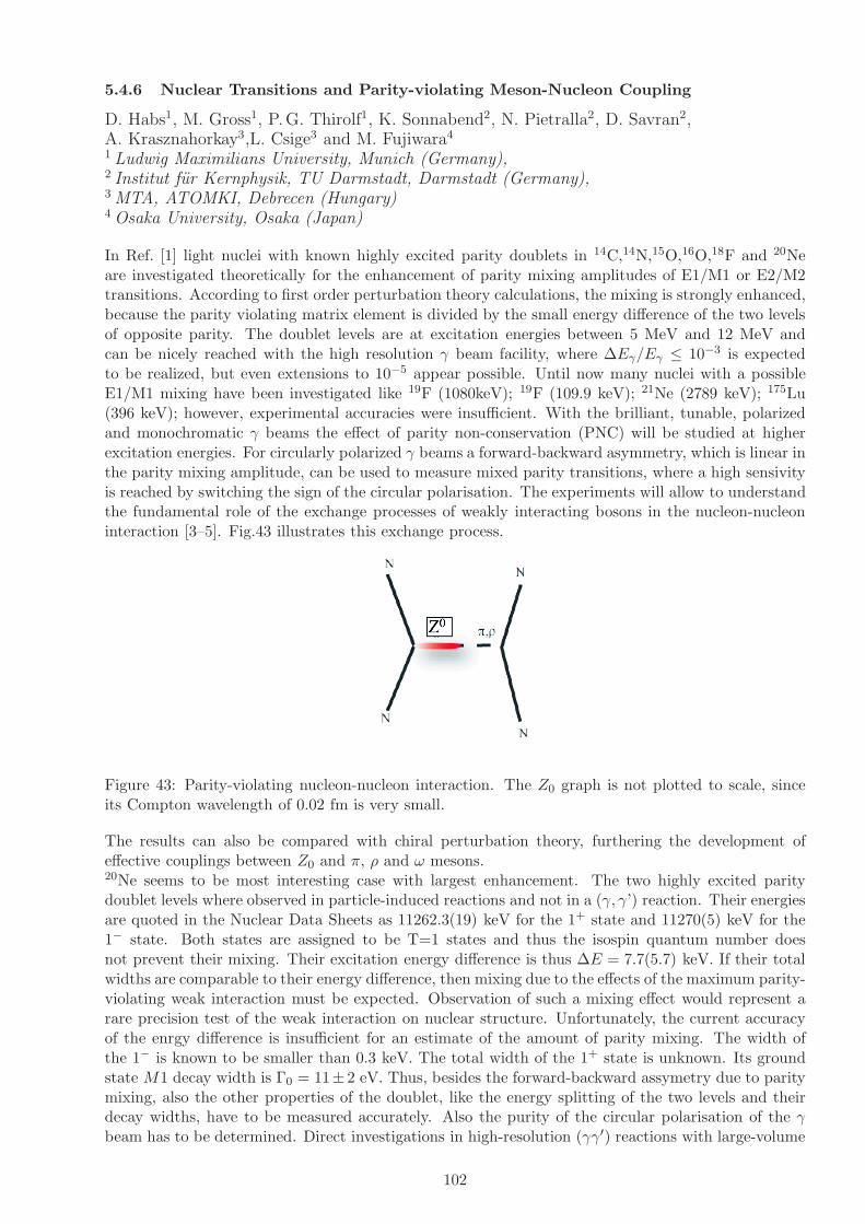
5.4.6 Nuclear Transitions and Parity-violating Meson-Nucleon Coupling
D. Habs1, M. Gross1, P.G. Thirolf1, K. Sonnabend2, N. Pietralla2, D. Savran2,A. Krasznahorkay3,L. Csige3 and M. Fujiwara4
1 Ludwig Maximilians University, Munich (Germany),2 Institut fur Kernphysik, TU Darmstadt, Darmstadt (Germany),3 MTA, ATOMKI, Debrecen (Hungary)4 Osaka University, Osaka (Japan)
In Ref. [1] light nuclei with known highly excited parity doublets in 14C,14N,15O,16O,18F and 20Neare investigated theoretically for the enhancement of parity mixing amplitudes of E1/M1 or E2/M2transitions. According to first order perturbation theory calculations, the mixing is strongly enhanced,because the parity violating matrix element is divided by the small energy difference of the two levelsof opposite parity. The doublet levels are at excitation energies between 5 MeV and 12 MeV andcan be nicely reached with the high resolution γ beam facility, where ∆Eγ/Eγ ≤ 10−3 is expectedto be realized, but even extensions to 10−5 appear possible. Until now many nuclei with a possibleE1/M1 mixing have been investigated like 19F (1080keV); 19F (109.9 keV); 21Ne (2789 keV); 175Lu(396 keV); however, experimental accuracies were insufficient. With the brilliant, tunable, polarizedand monochromatic γ beams the effect of parity non-conservation (PNC) will be studied at higherexcitation energies. For circularly polarized γ beams a forward-backward asymmetry, which is linear inthe parity mixing amplitude, can be used to measure mixed parity transitions, where a high sensivityis reached by switching the sign of the circular polarisation. The experiments will allow to understandthe fundamental role of the exchange processes of weakly interacting bosons in the nucleon-nucleoninteraction [3–5]. Fig.43 illustrates this exchange process.
Figure 43: Parity-violating nucleon-nucleon interaction. The Z0 graph is not plotted to scale, sinceits Compton wavelength of 0.02 fm is very small.
The results can also be compared with chiral perturbation theory, furthering the development ofeffective couplings between Z0 and π, ρ and ω mesons.20Ne seems to be most interesting case with largest enhancement. The two highly excited paritydoublet levels where observed in particle-induced reactions and not in a (γ, γ’) reaction. Their energiesare quoted in the Nuclear Data Sheets as 11262.3(19) keV for the 1+ state and 11270(5) keV for the1− state. Both states are assigned to be T=1 states and thus the isospin quantum number doesnot prevent their mixing. Their excitation energy difference is thus ∆E = 7.7(5.7) keV. If their totalwidths are comparable to their energy difference, then mixing due to the effects of the maximum parity-violating weak interaction must be expected. Observation of such a mixing effect would represent arare precision test of the weak interaction on nuclear structure. Unfortunately, the current accuracyof the enrgy difference is insufficient for an estimate of the amount of parity mixing. The width ofthe 1− is known to be smaller than 0.3 keV. The total width of the 1+ state is unknown. Its groundstate M1 decay width is Γ0 = 11± 2 eV. Thus, besides the forward-backward assymetry due to paritymixing, also the other properties of the doublet, like the energy splitting of the two levels and theirdecay widths, have to be measured accurately. Also the purity of the circular polarisation of the γbeam has to be determined. Direct investigations in high-resolution (γγ′) reactions with large-volume
102

Table 10: Candidate for PNC asymmetry in light nuclei
Nucleus Transition Ef1 Ef2 Amplif. fac.14C (0+, 1) → (2−, 1) 7340 keV 7010 keV 31±614N (1+, 0) → (1+, 0) 6203 keV 5691 keV 7.0± 2.0
(1+, 0) → (0+, 1) 8624 keV 8776 keV 40 ± 5(1+, 0) → (2−, 1) 9509 keV 9172 keV 45 ± 5
15O (1/2−, 1/2) → (1/2−, 1/2) 11025 keV 10938 keV 37±716O (0+, 0) → (2−, 0) 8879 keV 6917 keV 18±218F (1+, 0) → (1−, 0 + 1) 5605 keV 5603 keV 590±11020Ne (0+, 0) → ((1−, 0) 11270 keV 11262 keV 670±7000
Germanium detectors are highly desirable.
References
[1] A.I. Titov et al., J. Phys. G: Nucl. Part. Phys. 32, 1097 (2006).
[2] U.E.G. Berg et al., Phys. Rev. C 27, 2981 (1983).
[3] E. Adelberger et al., Nucl. Phys. A 396, 221c (1983).
[4] E. Adelberger et al., Ann. Rev. Nucl. Sci. 35 , 501 (85).
[5] B. Desplanques., Phys. Rep. 297, 1 (1998).
[6] R. Hajima et al., Nucl. Instr. and Meth. A 608, 557 (2009).
103
5.4.7 Study of pygmy and giant dipole resonances in lead isotopes by direct γ excitation
C.Borcea1, M.N.Harakeh2, A.Negret1 and N.V. Zamfir1
1Horia Hulubei National Institute for Physics and Nuclear Engineering, Bucharest - Magurele,070125, Romania2Kernfysisch Versneller Instituut, Zernikelaan 25, NL-9747 AA Groningen, The Netherlands
Pygmy dipole resonances (PDRs) in nuclei are frequently interpreted as a collective phenomenonrepresenting an oscillation of the neutrons in excess (to protons) with respect to the N=Z core whilegiant dipole resonances (GDRs) are seen as oscillations of the proton and neutron fluids with respectto each other. PDRs are placed much lower in energy than GDRs and they represent only a smallfraction of the total E1 strength (few percents), while GDRs, highly placed in energy, exhaust almostfully the E1 strength (TRK sum rule). The PDR occurs close to the neutron emission threshold and itsdecay is governed by the coupling to the large number of states around the threshold. Most frequentlymicroscopic models (RPA, RRPA, QPM, TDHF theory) are invoked to interpret and understand theexperimental results. From the experimental point of view, many measurements were carried outthroughout the chart of nuclides, much more for GDR than for PDR. The resonances were excitedby various means like light-particle or heavy-ion bombardment or directly by γ rays. Subsequentparticle and/or γ decay were recorded. When excited by γ rays, these were produced by positron-annihilation in flight, by bremsstrahlung, by Coulomb excitation (virtual γ rays) and more recently bydedicated γ sources based on Compton backscattering. The last technique has substantial advantageslike: the narrow width in energy, the easy energy variation and the fact that γ beams are polarized.The present proposal intends to measure the excitation function of the γ scattering cross section onseparated lead isotopes in a range of energies covering both PDR and GDR, i.e. until about 18 MeV.The measurements will be carried out at the high-resolution and high peak brilliance γ source of ELI-NP, using polarized beams. The expected output of the experiment consists of measured excitationfunctions for elastic and inelastic γ scattering revealing possible fine structures/splitting of PDR andGDR, excitation function with high resolution for (γ,n) and (γ,charged particle) channels, allowingto determine the branching ratios for various decay channels. The polarized beam will also allowdetermining the E1 or M1 type of excitation for the observed structures. The experimental setup willinclude large efficiency Ge detectors arranged in the vertical and horizontal planes as well as silicontelescopes for charged particles set up in a thin-wall evacuated reaction chamber around the target.The beam monitoring will be done by measuring with a Ge detector the incident γ flux scattered ona high-Z material at a small angle, few meters downstream from the target. The very well-defined γbeam would allow an effective shielding of the detectors used in the experiment from the monitoringsystem. Though the present proposal is rather exploratory for the potential of the γ source forsuch type of measurements, significant improvement and enrichment of present experimental data isexpected. The experiment will be a first step in a sequence of systematic investigations of PDR andGDR in neutron-rich nuclei.
104

5.4.8 Gamma scattering on nucleiThe Pygmy Dipole Resonance (PDR) of deformed nuclei
D. Savran1, N. Pietralla1, K. Sonnabend1,R.A. Ionescu2, D. Pantelica2, C. Hategan2
1 Institut fur Kernphysik, TU Darmstadt, Darmstadt (Germany)2 IFIN-HH, Bucharest (Romania)
Radiative (gamma ray) strength functions, especially dipole strength functions, are an importantingredient for the analysis of photodisintegration reactions (e.g. (γ, n)) and their inverses, radiativecapture reactions (e.g. neutron radiative capture, (n, γ), and proton radiative capture, (p, γ)).The radiative neutron capture is responsible for the production of heavy elements (elements beyondiron) in stars [1]. Neutron capture processes divide into two classes:
1. the slow neutron capture process (s-process) where the produced nucleus decays to a stablenucleus before further neutron capture occurs
2. the rapid neutron capture process (r-process) where the neutron flux is so high that the nucleuscapture many neutrons before it can decay
When the capture cross section is small we expect a build-up leading to larger abundances. Thishappens when the number of neutrons is magic (N=50, 82, 126) and this corresponds in beta stablenuclei to mass number A=90 (90Zr), ∼ 140 (138Ba and 140Ce - the most abundant of the rare earthelements), and 208 (208Pb which is double magic).Moreover, the proton radiative capture at small (at nuclear scale) energy and radiative disintegration(p-process responsible for production of some neutron deficient stable isotopes: N=50 92Mo, Z=50112Sn, N=82 144Sm) play an important role in stellar evolution.The standard theoretical tool to derive neutron capture cross sections for unstable isotopes relevantfor the s- and r-processes is the Hauser-Feshbach statistical model. The ingredients for the model arethe radiative strength functions and the neutron strength functions.Dipole strength functions can be obtained from photoabsorption cross sections σγ using (γ, n) reac-tions. These experiments are restricted to the energy region above the neutron separation energywhere the giant dipole resonance is located. Starting with [2, 3] it has been found that in the energyregion from 10 to 30 MeV the cross sections for all nuclei exhibit a resonance like structure due todipole electrical (E1) multipolarity of incoming gamma. With the availability of monoenergetic pho-tons from in flight annihilation of fast positrons obtained by pair production from bremsstrahlung(typical 1% energy resolution) and tagged bremsstrahlung the emphasis changes from the explorationof the absorption process to the understanding of the giant resonance states especially in light nucleiwhere the density of states is smaller than in heavier nuclei (see [4] for a review).The giant dipole resonance corresponds to the fundamental frequency of absorption of electric dipoleradiation by the nucleus and is most simply understood as the oscillations of the neutrons againstthe protons in the nucleus (semiclassical hydrodynamic models of Goldhaber and Teller [5] and Stein-wedel and Jensen [6]). Microscopically one construct the giant resonance from a superposition of(quasi)particle-(quasi)hole states based on the shell model or its extensions (HFB) [7]. In the schematicmodel of Brown and Bolsterli for doubled closed shell nuclei it was proven that one 1− state frommany possible particle-hole states is pushed up in energy due to the residual interaction and it collectsall the dipole electric transition strength.Therefore, the presence of the giant dipole resonance is a well established fact in all nuclei. Neverthe-less, the precise knowledge of the dipole strength on the low energy tail of the giant dipole resonance,especially the properties of the dipole strength at varying number of proton and neutrons, is an openproblems in nuclear physics. Moreover the dipole strength at low energy (below and around the neu-tron emission threshold) can have electric (pygmy dipole resonance) or magnetic character. Both parts,the electric dipole strength in vibrational nuclei (1− quadrupole-octupole two-phonon states, pygmyresonances close to the particle emission threshold [8]) as well as the magnetic dipole excitations (lowlying orbital scissors mode in deformed nuclei, high lying spin-flip mode [8, 9]) are interesting topicsin nuclear physics of stable and radioactive nuclei.
105
One clean way to probe the structure of the states of an atomic nucleus is to use electromagnetic probes:(forward) proton scattering, electron scattering and photon scattering (virtual photon scattering, i.e.Coulomb excitation/breakup or real photon scattering). The photon scattering is an ideal tool toinvestigate low-lying dipole strength in stable nuclei because of its selectivity to low spin states: thestates excited by electric and magnetic dipole transition from the ground state dominate the resonantgamma scattering.The new photon scattering experiments use two sources of photons: (partially linearly polarized)bremsstrahlung (high flux, 106photons/(keV · s), but continous spectrum) at Stuttgart Dynamitron(shut down in 2005), at S-DALINAC in Darmstadt, at 15MeV Linac in Gent [10] and at high currentelectron accelerator ELBE in Rossendorf and the high-flux, quasi-monochromatic photon sources,tuneable in energy, and of nearly 100% linear polarization by laser Compton back-scattering (lowertotal flux, 106photons/s, but small energy spread of the order of 100 keV at 10 MeV) at HIγSat Duke [11] and in Japan. The monochromaticity of this novel photon beam together with highresolution and high efficiency γ-spectrometres will allow a detailed study of the fragmentation of thedipole strength and its dependence on the parameters characterizing different nuclei: shell efects,deformation etc.The critical parameters of the photon beam are: small energy spread to reduce both the backgroundCompton scattering and to allow a selective excitation of states if the density of dipole excited states inthe energy region of interest is low (spherical nuclei) or at least to explore with high energy resolutionthe dipole strength when the density of excited states is large (deformed nuclei) and high intensityto obtain statistically relevant experimental data in resonable time and with smaller target (especiallyimportant for long-lived beta unstable nuclei or isotopically pure targets).Even for very good energy resolution, the energy width of the beam (keV ) is large compared to thelevel radiative widths ( µeV − eV ), and the experimental signal is the cross section integrated overresonance which is proportional with the radiative width.Up to now the experimental studies of the low lying electric dipole strength was done for few lightnuclei, 26Mg [12], 27Al [13] and for nuclei with magic number of protons and/or neutrons: N=50(87Rb [14], 88Sr [15], 89Y [16], 90Zr [17]) or close to N=50 (92Zr and 96Mo [18], even Mo isotopes [19],Zr isotopes [20]), Z=50 (Sn isotopes [21]), N=82 (138Ba [22]), or close to N=82 (142Ce [23]), N=126,Z=82 (208Pb [24]) and Pb isotopes [24].As possible higly interesting experimental topics we propose:
• Studies of the pygmy dipole resonance via resonant photon scattering for neutron closed shellnuclei
This nuclei are important for the slow neutron capture process in stars and the systematic studyof the pygmy dipole resonance below the particle emission threshold will allow to understandthe source of this strength decoupled from the giant resonance. We mention that Lane, whointroduced the concept of ”pygmy resonance” in 1971 [25], discussed the possibility that thedipole electric strength decoupled from the giant resonance in the region of neutron emissionthreshold is due to the small overlap with other states of some low angular momentum neutronsingle particle threshold states (they spread out of the nucleus at the expense of being depressedinside). This avoided mixing of some states into the giant dipole resonance due to boundaryconditions is worth studying with the modern experimental facilities as it will constraints alsothe behaviour of this pygmy strength in nuclei far from stability. We are not aware of any testof this idea in recent photon scattering experiments, but the behaviour of the pygmy dipolestrength in N=50 stable even isotones (136Xe - 144Sm) [26] indicates a larger pygmy dipolestrength around 6MeV for 136Xe (neutron separation energy ∼ 8 MeV) than for 144Sm (neutronseparation energy ∼ 11 MeV). The same behaviour is apparent for Z=50 Sn isotopes [27].
• Studies of the pygmy dipole resonance via resonant photon scattering for deformed nuclei
The behaviour of the low lying electric dipole strength for deformed nuclei is an other interestingtopic. The main question is how the incresed deformation for nuclei far from closed shell affectthe total strength in the pygmy resonance region. One expects that the deformation will increase
106
the 1− level density (for even-even nuclei) in the pygmy resonance energy region and the strengthwill be spreaded over many more individual resonances.
• Studies of the dipole strength in light nuclei
The light stable nuclei are involved in radiative proton capture processes in stars and the be-haviour of their dipole electric strength both below and above proton separation threshold isrelevant for nuclear astrophysics. In this light nuclei the electric dipole strength is fragmenteddue to the low density of states. Therefore the investigation of individual resonances is experi-mentally easier. Moreover it seems that the measurement of radiative width above the protonseparation threshold is feasible (the neutron threshold is higher and the proton width remainssmall, comparable with the radiative width, due to the Coulomb barrier). Such measurementswill better constrain the radiative width for resonances relevant for proton capture reactions atstellar energies.
Phenomena in nuclear physics which have recently attracted great interest of experimentalists as wellas theoreticians are collective electric dipole modes below the Giant Dipole Resonance, frequentlydenoted as Pygmy Dipole Resonances (PDR) [8, 28]. Evidence for such excitation modes has beenfound in many stable spherical nuclei below the particle separation energies [4,5,26,29,30]. In additionabove threshold energies a similar observation has been made recently in exotic nuclei with a largeneutron excess [33, 34]. The experiments are accompanied by intense theoretical investigations toexplain the nature of this nuclear phenomenon, see e.g. [35] and references therein. Understandingthe nature of the low-lying E1 strength will, e.g., help to constrain the symmetry energy in atomicnuclei [36] and has an impact on reaction rates of astrophysical interest [37, 38] as well as on thephotodisintegration of ultra-high-energy cosmic rays [39]. However, the experimental database isstill scarce, especially for non-magic nuclei. Consequently the influence of deformation on the PDRstrength has yet not been investigated experimentally, while recently first relativistic Random PhaseApproximation (RPA) calculations of low-lying E1 strength in deformed nuclei became available [40,41]. It is thus of mandatory importance to extend the experimental investigations towards deformednuclei in order to provide the necessary test grounds for these modern calculations.The method of choice for the investigation of low-lying E1 strength below the particle threshold instable nuclei is the method of real photon scattering [8, 42]. It assures a clean excitation mechanismand allows a model independent extraction of quantum numbers such as multipolarities, absolutestrengths, decay branching ratios, and parities. Up to now, nearly exclusively bremsstrahlung hasbeen used as high energy photon source. However, the investigation of the E1 strength close to theparticle thresholds in deformed nuclei has been hindered by the extremely high level densities. Inaddition, the determination of parities is mandatory for the clean identification of E1 strength indeformed nuclei, which is difficult to achieve with unpolarized bremsstrahlung. These drawbackscan be overcome by using Linear Compton Backscattered (LCB) photons, as has partly been shownin [5, 43]. The benefits of using a monoenergetic polarized LCB source is two-fold:
• The monoenergetic character of the beam will allow a energy dependent determination of thephoton absorbtion cross sections even in the vicinity of very high level densities.
• The polarized character of the beam will allow for an unambiguous disentanglement of E1, M1and E2 contributions to the photon absorption cross section.
Compared to the experiments using LCB photons performed in [5,43], the superior properties of ELIwill improve the sensitivity of the experiments by at least one order of magnitude and thus will allowthe investigation of the PDR also in deformed nuclei.
References
[1] E.M. Burbidge, G.R. Burbidge, W.A. Fowler, F. Hoyle, Rev. Mod. Phys. 29 (1957) 547
G. Wallerstein et al., Rev. Mod. Phys. 69 (1997) 995
C. Iliadis, Nuclear Physics of Stars, Wiley-VCH Verlag, Weinheim, 2007
107

[2] W. Bothe, W. Gentner, Z. Physik 106 (1937) 236
[3] G.C. Baldwin, G.S. Klaiber, Phys. Rev. 71 (1947) 3
[4] B.L. Berman, S.C. Fultz, Rev. Mod. Phys. 47 (1975) 713
[5] M. Goldhaber, E. Teller, Phys. Rev. 74 (1948) 1046
[6] H. Steinwedel, H. Jensen, Z. Naturforsch. 5A (1950) 413
[7] G.E. Brown, M. Bolsterli, Phys. Rev. Lett 3 (1959) 472
[8] U. Kneissl, N. Pietralla, A. Zilges, J. Phys. G 32 (2006) R217.
[9] K. Heyde, P. von Neumann-Cosel, A. Richter, nucl-ex/1004.3429, to appear in Rev. Mod. Phys.
[10] K. Govaert et al., Nucl. Inst. Meth. A337 (1994)265
[11] H.R. Weller et al., Prog. Part. Nucl. Phys. 62 (2009) 257
[12] R. Longland et al., Phys. Rev. C80 (2009) 055803
[13] N. Pietralla et al., Phys. Rev. C51 (1995) 1021
[14] L. Kaubler et al., Phys. Rev. C65 (2002) 054315
[15] N. Pietralla et al., Phys. Rev. C65 (2002) 047305
L. Kaubler et al., Phys. Rev. C70 (2004) 064307
R. Schwengner et al., Phys. Rev. C76 (2007) 034321
[16] N. Benouaret et al., Phys. Rev. C79 (2009) 014303
[17] R. Schwengner et al., Phys. Rev. C78 (2008) 064314
[18] C. Fransen et al., Phys. Rev. C70 (2004) 044317
[19] G. Rusev et al., Phys. Rev. C79 (2009) 061302(R)
M. Erhard et al., Phys. Rev. C81 (2010) 034319
[20] H. Utsunomiya et al., Phys. Rev. Lett. 100 (2008) 162502
[21] H. Utsunomiya et al., Phys. Rev. C80 (2009) 055806
[22] R.-D. Herzberg et al., Phys. Rev. C60 (1999) 051307
N. Pietralla et al., Phys. Rev. Lett. 88 (2002) 012502
A.P. Tonchev et al., Phys. Rev. Lett. 104 (2010) 072501
[23] A. Gade et al., Phys. Rev. C69 (2004) 054301
[24] N. Ryezayeva et al., Phys. Rev. Lett. 89 (2002) 272502
J. Enders et al., Nucl. Phys. A724 (2003) 243
[25] A.M. Lane, Ann. Phys. 63 (1971) 171
B. Gyarmati, A.M. Lane, J. Zimanyi, Phys. Lett. 50B (1974) 316
L.P. Csernai, J. Zimanyi, B. Gyarmati, R.G. Lovas, Nucl. Phys. A294 (1978) 41
[26] S. Volz, N. Tsoneva, M. Babilon, M. Elvers, J. Hasper, R.-D. Herzberg, H. Lenske, K. Lindenberg,D. Savran, A. Zilges, Nucl. Phys. A779 (2006) 1
[27] B. Ozel et al., Nucl. Phys. A788 (2007) 385c
108

[28] G. A. Bartholomew, E. D. Earl, A. J. Ferguson, J. W. Knowles, M. A. Lone, Adv. Nucl. Phys. 7(1973) 229.
[29] K. Govaert, F. Bauwens, J. Bryssinck, D. De Frenne, E. Jacobs, W. Mondelaers, L. Govor, V. Y.Ponomarev, Phys. Rev. C 57 (1998) 2229.
[30] R. Schwengner, G. Rusev, N. Benouaret, R. Beyer, M. Erhard, E. Grosse, A. R. Junghans,J. Klug, K. Kosev, L. Kostov, C. Nair, N. Nankov, K. D. Schilling, A. Wagner, Phys. Rev. C 76(2007) 034321.
[31] D. Savran, M. Fritzsche, J. Hasper, K. Lindenberg, S. Muller, V. Y. Ponomarev, K. Sonnabend,A. Zilges, Phys. Rev. Lett. 100 (2008) 232501.
[32] A. P. Tonchev, S. L. Hammond, J. H. Kelley, E. Kwan, H. Lenske, G. Rusev, W. Tornow,N. Tsoneva, Phys. Rev. Lett. 104 (2010) 072501.
[33] P. Adrich, A. Klimkiewicz, M. Fallot, K. Boretzky, T. Aumann, D. Cortina-Gil,U. Datta Pramanik, Th. W. Elze, H. Emling, H. Geissel, M. Hellstrom, K. L. Jones, J. V. Kratz,R. Kulessa, Y. Leifels, C. Nociforo, R. Palit, H. Simon, G. Surowka, K. Summerer, W. Walus,Phys. Rev. Lett. 95 (2005) 132501.
[34] A. Klimkiewicz, P. Adrich, K. Boretzky, M. Fallot, T. Aumann, D. Cortina-Gil, U. D. Pramanik,T. W. Elze, H. Emling, H. Geissel, M. Hellstroem, K. L. Jones, J. V. Kratz, R. Kulessa, Y. Leifels,C. Nociforo, R. Palit, H. Simon, G. Surowka, K. Suemmerer, S. Typel, W. Walus, Nucl. Phys.788 (2007) 145.
[35] N. Paar, T. Niksic, D. Vretenar, P. Ring, Phys. Lett. B 606 (2005) 288.
[36] J. Piekarewicz, Phys. Rev. C 73 (2006) 044325.
[37] S. Goriely, Phys. Lett. B 436 (1998) 10.
[38] S. Goriely, E. Khan, M. Samyn, Nucl. Phys. A739 (2004) 331.
[39] E. Khan, S. Goriely, D. Allard, E. Parizot, T. Suomijarvi, A. J. Koning, S. Hilaire, M. C. Dui-jvestijn, Astro. Phys. 23 (2005) 191.
[40] D. Pena Arteaga, P. Ring, Phys. Rev. C 77 (2008) 034317.
[41] D. Pena Arteaga, E. K. P. Ring, Phys. Rev. C 79 (2009) 034311.
[42] U. Kneissl, H. H. Pitz, A. Zilges, Prog. Part. Nucl. Phys. 37 (1996) 349.
[43] N. Pietralla, Z. B. V. N. Litvinenko, S. Hartman, F. F. Mikhailov, I. V. Pinayev, G. S. M. W.Ahmed, J. H. Kelley, S. O. Nelson, R. Prior, K. Sabourov, A. P. Tonchev, H. R. Weller, Phys.Rev. Lett. 88 (2001) 012502.
109
5.4.9 Fine-structure of Photo-response above the Particle Threshold:the (γ ,α), (γ,p) and (γ ,n) Reactions
N. Pietralla1, D. Savran1, K. Sonnabend1,A. Negret2 and V. Corcalciuc2
1 Institut fur Kernphysik, TU Darmstadt, Darmstadt (Germany)2 IFIN-HH, Bucharest, Romania
The excitation energy region around the particle separation threshold is of particular importance fornuclear physics. On one hand side this energy region is of interest for theoretical reasons because thecoupling of bound quantum states to the continuum of unbound states requires an extended formalism,the mastering of which becomes extremely important for exotic nuclei near the drip-lines where allstructures are weakly bound [1]. Examples are the famous halo-nuclei like e.g. 11Li [2]. On the otherhand this energy region covers the Gamow-window of thermally driven reactions of nucleons withheavy nuclei. Its understanding is a prerequisite for the modelling of nuclear reaction cascades in hotcosmic objects and thus for nucleosynthesis.Below the threshold all excited resonances must decay by γ emission. They can be studied withthe typical high energy resolution of semiconductor-detector technology (e.g., 5 keV at 8 MeV). Thephoto-response below the particle separation energy is currently investigated in nuclear resonancefluorescence experiments [1] at existing γ-beam facilities such as the bremsstrahlung facilities at theS-DALINAC electron accelerator in Darmstadt, Germany, [4] or at the High Intensity γ-ray Source(HIγS) at Duke Univ., Durham, NC, U.S.A [5].Above the threshold the particle-decay channel opens up. Either no γ rays can be observed at all ortheir intensity cannot be used as a measure for the total electromagnetic excitation strength to theresonance due to the unknown particle-decay branching ratio. Neutrons cannot be measured with acompetitive energy resolution at acceptable solid-angle coverage.An intense and high-energy resolving γ-ray beam from ELI-NP will open up new horizons for theinvestigation of the nuclear photo-response at and above the separation threshold. Alternativelyto nuclear fluorescence, a photo-transmission experiment could be performed. A reduction in thephoto transmission is directly proportional to the photo-excitation cross section. A measurementof the transmitted intensity is sensitive to the fine-structure in the energy window of the photonbeam. A high-resolution γ-ray beam with energy width dE/E ≤ 10−3 will allow for the performanceof transmission experiments with semiconductor-detector resolution even in the regime of unboundresonances. We expect a tremendous increase of insight into nuclear structure in the continuum anda deepened understanding of the structure of the nuclear Gamow-window.The gamma induced nuclear reactions mentioned in the title were extensively studied during the yearsusing mostly the gamma rays from bremsstrahlung and to a smaller extent, Compton back scattering.Generally, there is a clear difference among the three reactions because the Coulomb barrier makes thestudy of the (γ,α) reaction more difficult than the study of the (γ,p) reaction which is more difficultthan (γ,n). Consequently, in the cross section data base EXFOR [6] there are 21 entries for (γ,α)cross sections, 278 entries for (γ,p) cross sections and 832 entries for (γ,n) cross sections. Further, theNSR database [7] displays 104 references for the (γ,α) reaction, 1052 references for the (γ,p) reactionand 1394 references corresponding to the (γ,n) reaction.A major scientific interest related to the study of these reactions comes from Astrophysics. The nucleiheavier that Z=26 (iron) are synthesized mainly by neutron-capture reactions (r- and s- processes).The neutron deficient stable isotopes with Z>34 (Se) and Z<80 (Hg) that are shielded from rapidneutron capture by stable nuclei are referred as p-nuclei and their formation occurs, most probably,during the supernova explosions. All p-nuclei can be synthesized from the destruction of pre-existingnuclei of the s- and r-type by a combination of (p,γ) captures and (γ,n), (γ,p) or (γ,α) photoreactions.It is to observe that in the nuclear mass region of interest for the p-process and not too far fromstability, the (γ,α) reactions usually have much larger rates than the (γ,p) reactions because in thatregion the α particles have small or even negative binding energies, whereas typical proton separationenergies are of the order of several MeV. Therefore, when the α particle is replaced by a proton, thesmaller Coulomb barrier does not compensate the strong increase in binding energy Sp − Sα and the
110
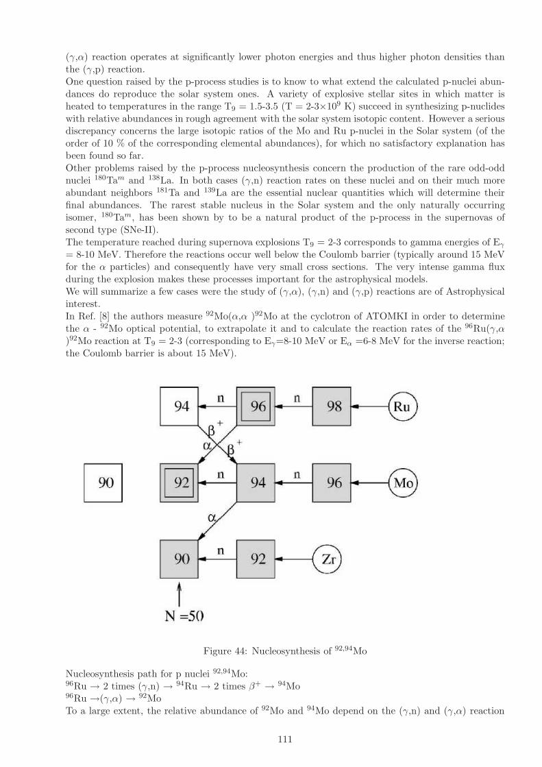
(γ,α) reaction operates at significantly lower photon energies and thus higher photon densities thanthe (γ,p) reaction.One question raised by the p-process studies is to know to what extend the calculated p-nuclei abun-dances do reproduce the solar system ones. A variety of explosive stellar sites in which matter isheated to temperatures in the range T9 = 1.5-3.5 (T = 2-3×10⁹ K) succeed in synthesizing p-nuclideswith relative abundances in rough agreement with the solar system isotopic content. However a seriousdiscrepancy concerns the large isotopic ratios of the Mo and Ru p-nuclei in the Solar system (of theorder of 10 % of the corresponding elemental abundances), for which no satisfactory explanation hasbeen found so far.Other problems raised by the p-process nucleosynthesis concern the production of the rare odd-oddnuclei 180Tam and 138La. In both cases (γ,n) reaction rates on these nuclei and on their much moreabundant neighbors 181Ta and 139La are the essential nuclear quantities which will determine theirfinal abundances. The rarest stable nucleus in the Solar system and the only naturally occurringisomer, 180Tam, has been shown by to be a natural product of the p-process in the supernovas ofsecond type (SNe-II).The temperature reached during supernova explosions T9 = 2-3 corresponds to gamma energies of Eγ
= 8-10 MeV. Therefore the reactions occur well below the Coulomb barrier (typically around 15 MeVfor the α particles) and consequently have very small cross sections. The very intense gamma fluxduring the explosion makes these processes important for the astrophysical models.We will summarize a few cases were the study of (γ,α), (γ,n) and (γ,p) reactions are of Astrophysicalinterest.In Ref. [8] the authors measure 92Mo(α,α )92Mo at the cyclotron of ATOMKI in order to determinethe α - 92Mo optical potential, to extrapolate it and to calculate the reaction rates of the 96Ru(γ,α)92Mo reaction at T9 = 2-3 (corresponding to Eγ=8-10 MeV or Eα =6-8 MeV for the inverse reaction;the Coulomb barrier is about 15 MeV).
Figure 44: Nucleosynthesis of 92,94Mo
Nucleosynthesis path for p nuclei 92,94Mo:96Ru → 2 times (γ,n) → 94Ru → 2 times β+ → 94Mo96Ru →(γ,α) → 92MoTo a large extent, the relative abundance of 92Mo and 94Mo depend on the (γ,n) and (γ,α) reaction
111

rates on 96Ru (for details the rp contribution to 92Mo and the s contribution to 94Mo should alsobe known). When the astrophysical reaction rates for the (γ,α) reaction are calculated with variouspotentials, they come out within two orders of magnitude. The authors claim that their extrapolationleads to an error of 15% for this reaction rate; however their result is a factor 2 lower than the presentlyrecommended value.Theoretical studies addressing a very similar issue are presented in Refs. [9, 10]: the 146Sm/144Smabundance that depends on the 148Gd(γ,n)147Gd / 148Gd(γ,α)144Sm reaction rates. The authors ofthese studies pledge for the experimental determination of the cross sections.Ref. [11] presents a recent study where the photodisintegration reactions of nuclei of interest forAstrophysics were directly measured. The authors measured the photodisintegration of 92Mo and144Sm using the activation method. The bremsstrahlung facility ELBE was used: electron beam withenergy up to 20 MeV, average current 1 mA, and photon flux of 109 cm−2s−1MeV−1. The targetsare discs or powder of 2-4 g and diameter of 20 mm. A pneumatic delivery system transports theactivated samples to the measurement site (HPGe detectors). The measurements are relative to the197Au(γ,n) standard cross section.Finally, we mention the experiments performed at the National Institute of Advanced IndustrialScience and Technology (AIST) using also a gamma source based on laser inverse Compton scattering(LCS). There, the γ beam with a rather limited intensity (104−5 photon/s) has been used to measurecross sections of 9Be(γ,n)αα of interest for the nucleosynthesis in supernovae [16], of 181Ta(γ,n)180Tafor the p-process nucleosynthesis [17], and D(γ,n)p for big bang nucleosynthesis [18]. The γ energyis varied in the region of 1-40 MeV by tuning the electron beam energy from 200 to 800 MeV.An energy resolution of 1-10% in FWHM and nearly 100% polarization are achieved. Because of themonochromaticity, the LCS γ beam is best suited to excitation function measurements of photoneutronreactions near threshold with enriched-target material of the order of 1 g. In addition, photo-activationof natural foils can be done for nuclei whose isotopic abundance is sufficiently large.In conclusion, the gamma-induced nuclear reactions of astrophysical interest were extensively studiedduring the years but still represent a challenge for the experimental and theoretical work. The difficultyarises from the very small cross sections due to the fact that the reactions occur deep below theCoulomb barrier especially for the case of (γ ,α ) reactions. Therefore a very intense gamma sourcewould be of interest for such reactions.The particle detection techniques cover a variety of methods: from direct detection of neutrons (scintil-lators), activation of targets, direct detection of charged particles etc. For low energy charged particles(particularly alpha particles), a variety of active reaction chambers have been designed (TPC-timeprojection reaction chambers). They act in the same time as target and as detector, offering theadvantage of a near 4π detection geometry, a nearly 100% detection efficiency etc. Often, in measure-ments using TPC, the background events are dominant (sometimes 90% or more of all events) andspecial care must be taken in order to eliminate them.
References
[1] B. Jonson, Phys. Rep. 389 (2004) 1
[2] J. Dobaczewski, I. Hamamoto, W. Nazarewicz, J.A. Sheikh, Phys. Rev. Lett. 72 (1994) 981.
[3] U. Kneissl, N. Pietralla, A. Zilges, J. Phys. G 32 (2006) R217.
[4] D. Savran, M. Fritzsche, J. Hasper, K. Lindenberg, S. Muller, V. Y. Ponomarev, K. Sonnabend,A. Zilges, Phys. Rev. Lett. 100 (2008) 232501.
[5] A. P. Tonchev, S. L. Hammond, J. H. Kelley, E. Kwan, H. Lenske, G. Rusev, W. Tornow,N. Tsoneva, Phys. Rev. Lett. 104 (2010) 072501.
[6] Experimental Nuclear Reaction Data (EXFOR), http://www.nndc.bnl.gov/exfor/exfor00.htm
[7] Nuclear Science References Database (NSR), http://www.nndc.bnl.gov/nsr/index.jsp
112

[8] Zs. Fulop et al, Physics Review C 64, 065805 (2009).
[9] T. Rauscher, F.K. Thielemann and H. Oberhummer, The Astrophysical Journal 451, L37 (1995).
[10] S.E. Woosley and W.M. Howard, The Astrophysical Journal 354, L21 (1990).
[11] C. Nair et al., Journal of Physics G35, 014036 (2008).
[12] M. Gai et al., TUNL XLVII Progress report, 118 (2008).
[13] M. Gai et al., TUNL XLVII Progress report, 154 (2008).
[14] H. Weller et al., Progress in Particle and Nuclear Physics 62, 257 (2009).
[15] H. Utsunomiya, P. Mohr, A. Zilges, Nucl. Phys. A777, 459 (2006).
[16] K. Sumiyoshi, et al, Nucl. Phys. A709, 467 (2002).
[17] H. Utsunomiya, et al, Phys. Rev. C67, 015807 (2003).
[18] K.Y. Hara, et al, Phys. Rev. D68, 072001 (2003).
113

5.4.10 Nuclear Resonance Fluorescence on Rare Isotopes and Isomers
N. Pietralla1, D. Savran1, K. Sonnabend1
1 Institut fur Kernphysik, TU Darmstadt, Darmstadt (Germany)
Nuclear studies with the powerful experimental method of Resonance Fluorescence have been possibleup to now only if sufficient amounts of (preferably isotopically enriched) target material on the orderof about 1 g has been available. The production of such an amount of target material is not alwayspossible at a reasonable cost (e.g., the worlds rarest naturally occuring isotope 180Ta costs about $
10,000 per mg at an enrichment of 5%). The advances in γ-ray beam brilliance at ELI will increasethe sensitivity of NRF experiments by the same factor and thus it offers the opportunity to performNRF studies on small target samples whose amounts could be reduced with respect to todays NRFexperiments by the same factor. This opens up an entire new area of applicability of the NRF methodto materials that may be available only in quantities of a few mg.The dipole response of the long-lived radioactive isotope 14C, the basis of radio-carbon dating method,will be accessible. These experiments will shed light on the neutron-spectroscopic factors for the p-and sd-shell orbitals in that mass region that nowadays is accessible to ab initio no-core shell modelscalculations.Nuclear high-spin K isomers are known to be examples of highly-deformed nuclear structures. Dueto their simple Nilsson-model wave function they offer a unique laboratory for the study of verydeformed nuclear systems. Nuclear spectroscopy experiments with hadronic probes have previouslybeen performed on the the long-lived K-isomer of 178Hf. An investigation of the E1 and M1 responseof the highly-deformed isomer using NRF on an enriched isomeric sample of a few mg will enable usto study the phenomenon of quadrupole-octupole coupling (E1) or the nuclear scissors mode (M1) ata nuclear deformation that has not been accessible for these types of investigations before.
References
[1] U. Kneissl, N. Pietralla, A. Zilges, J. Phys. G 32 (2006) R217.
114
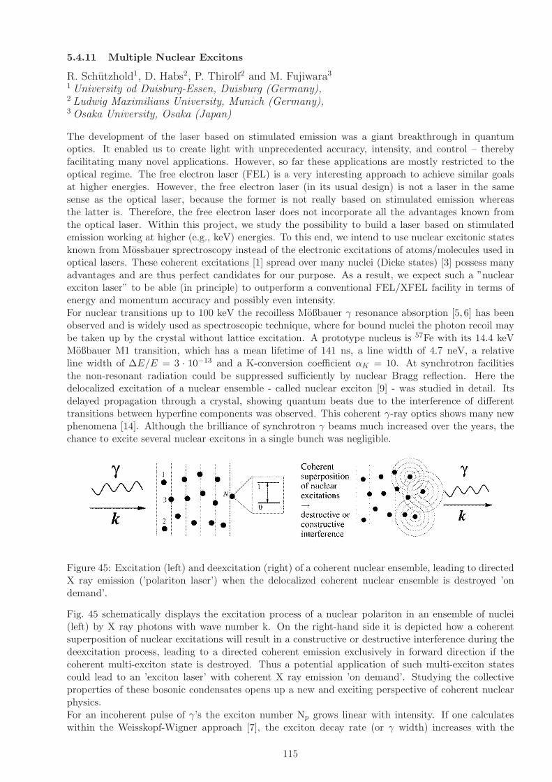
5.4.11 Multiple Nuclear Excitons
R. Schutzhold1, D. Habs2, P. Thirolf2 and M. Fujiwara3
1 University od Duisburg-Essen, Duisburg (Germany),2 Ludwig Maximilians University, Munich (Germany),3 Osaka University, Osaka (Japan)
The development of the laser based on stimulated emission was a giant breakthrough in quantumoptics. It enabled us to create light with unprecedented accuracy, intensity, and control – therebyfacilitating many novel applications. However, so far these applications are mostly restricted to theoptical regime. The free electron laser (FEL) is a very interesting approach to achieve similar goalsat higher energies. However, the free electron laser (in its usual design) is not a laser in the samesense as the optical laser, because the former is not really based on stimulated emission whereasthe latter is. Therefore, the free electron laser does not incorporate all the advantages known fromthe optical laser. Within this project, we study the possibility to build a laser based on stimulatedemission working at higher (e.g., keV) energies. To this end, we intend to use nuclear excitonic statesknown from Mossbauer sprectroscopy instead of the electronic excitations of atoms/molecules used inoptical lasers. These coherent excitations [1] spread over many nuclei (Dicke states) [3] possess manyadvantages and are thus perfect candidates for our purpose. As a result, we expect such a ”nuclearexciton laser” to be able (in principle) to outperform a conventional FEL/XFEL facility in terms ofenergy and momentum accuracy and possibly even intensity.For nuclear transitions up to 100 keV the recoilless Moßbauer γ resonance absorption [5, 6] has beenobserved and is widely used as spectroscopic technique, where for bound nuclei the photon recoil maybe taken up by the crystal without lattice excitation. A prototype nucleus is 57Fe with its 14.4 keVMoßbauer M1 transition, which has a mean lifetime of 141 ns, a line width of 4.7 neV, a relativeline width of ∆E/E = 3 · 10−13 and a K-conversion coefficient αK = 10. At synchrotron facilitiesthe non-resonant radiation could be suppressed sufficiently by nuclear Bragg reflection. Here thedelocalized excitation of a nuclear ensemble - called nuclear exciton [9] - was studied in detail. Itsdelayed propagation through a crystal, showing quantum beats due to the interference of differenttransitions between hyperfine components was observed. This coherent γ-ray optics shows many newphenomena [14]. Although the brilliance of synchrotron γ beams much increased over the years, thechance to excite several nuclear excitons in a single bunch was negligible.
Figure 45: Excitation (left) and deexcitation (right) of a coherent nuclear ensemble, leading to directedX ray emission (’polariton laser’) when the delocalized coherent nuclear ensemble is destroyed ’ondemand’.
Fig. 45 schematically displays the excitation process of a nuclear polariton in an ensemble of nuclei(left) by X ray photons with wave number k. On the right-hand side it is depicted how a coherentsuperposition of nuclear excitations will result in a constructive or destructive interference during thedeexcitation process, leading to a directed coherent emission exclusively in forward direction if thecoherent multi-exciton state is destroyed. Thus a potential application of such multi-exciton statescould lead to an ’exciton laser’ with coherent X ray emission ’on demand’. Studying the collectiveproperties of these bosonic condensates opens up a new and exciting perspective of coherent nuclearphysics.For an incoherent pulse of γ’s the exciton number Np grows linear with intensity. If one calculateswithin the Weisskopf-Wigner approach [7], the exciton decay rate (or γ width) increases with the
115

number of nuclei in the wave length volume and soon exceeds the width due to conversion. Then anavalanche-like growth of the linewidth occurs and more and more photons of the much broader drivingX-ray beam may join the multiple exciton condensate. Due to the required recoilless Mossbauer-likeabsorption we here will use rather low energy γ rays in the 100 keV range. While we get multipleexcitons with the γ beam, the exciton laser should be excited with coherent γ photons from therelativistic mirror. In this scenario a quadratic growth of the exciton number could be expected forcoherent pumping with X rays produced by the ELI-NP laser and a relativistic mirror. ] A coherentlyexcited nuclear state in a rotating sample aquires a phase shift and the radiative decay of the excitedstate proceeds in the rotated direction. This effect is called light house effect [17–21] and can be usedto separate the radiation from the nuclear decay from the primary exciting beam.
References
[1] D. Habs et al., Eur. Phys. J. D 55, 279 (2009).
[2] G.V. Smirnov et al., Propagation of nuclear polaritons through a two-target system: Effect ofinversion targets, Ohys. Rev. a 71, 023804 (2005).
[3] R.H. Dicke; Coherence in spontaneous radiation processes, Phys. Rev. 93, 99 (1954).
[4] T. Holstein and H. Primakoff, Phys. Rev. 58, 1098 (1940).
[5] R.L. Mossbauer, Z. Physik 151, 124 (1958), Naturw. 45, 538 (1958).
[6] R.L. Mossbauer, Z. Naturforsch. 14a, 211 (1959).
[7] M.O. Scully and M.S. Zubairy, Quantum Optics, Cambridge University Press, Cambridge, England(1997).
[8] H.J. Lipkin; Coherent effects in the transitions between states containing several nuclear excitons p.128; in “ Multiple Facets of Quatization and Supersymmetry, Michael Marinov Memorial Volume;edt.: M. Olshanetsky and A. Vainstein, World Scientific (2000).
[9] G.V. Smirnov et al., Propagation of nuclear polaritons through a two-target system: Effect ofinversion targets, Ohys. Rev. a 71, 023804 (2005).
[10] U.v. Burck; Hyp. Int. 123/124, 483 (1999)
[11] M.O. Scully et al., Phys. Rev. Lett. 96, 010501 (2006).
[12] D.C. Burnham and R.Y. Chao; Phys. Rev. 188, 667 (1p69).
[13] D. Frohlich et al., Phys. Rev. Lett. 67, 2343 (1991).
[14] J.P. Hannon and G.T. Trammell; Coherent γ-optics, Hyp. Int. 123/124, 127 (1999).
[15] N.E. Rehler and J.H. Eberly; Superradiance, Phys. Rev. A 3, 1735 (1971).
[16] Y.Y. Shuydku et al., Phys. Rev. Lett. 77, 3232 (1996).
[17] R. Roehlsberger et al., Phys. Rev. Lett. 84, 1007 (2000).
[18] R. Roehlsberger et al., Nucl. Inst. and Meth. A 467, 1473 (2001).
[19] T. Roth et al., Phys. Rev. B 71, 140401(R) (2005).
[20] I. Sergneev et al., Phys. Rev. Lett. 99, 097601 (2007).
[21] I. Sergneev et al., Phys. Rev. B 78, 214436 (2008).
116

5.5 Stand-alone γ/e− Facility for Astrophysics
The production of heavy elements in the Universe, a central question of astrophysics, will be studiedwithin ELI-NP in several experiments. While we want to address the s-process and p-process with theγ beam, we also plan to study the r-process at the N=126 waiting point by producing these neutron-rich nuclei via fission-fusion reactions with the APOLLON-type laser. This close interaction betweennuclear physics and astropyhisics will be very productive.
5.5.1 Neutron Capture Cross Section of s-Process Branching Nuclei with Inverse Re-actions
K. Sonnabend1, N. Pietralla1, D. Savran1
1 Institut fur Kernphysik, TU Darmstadt, Darmstadt (Germany)
The heavy elements above the so-called iron peak are mainly produced in neutron capture processes:the r process (r: rapid neutron capture) deals with high neutron densities well above 1020 cm−3
and temperatures in the order of 2 − 3 · 109 K. It is thought to occur in explosive scenarios like e.g.supernovae [1,2]. In contrast, the average neutron densities during s-process nucleosynthesis (s: slowneutron capture) are rather small (nn ≈ 108 cm−3), i.e. the neutron capture rate λn is normally wellbelow the β-decay rate λβ and the reaction path is close to the valley of β stability [3–5]. However,during the peak neutron densities branchings occur at unstable isotopes with half-lives as low as severaldays. While the half-lives of these branching points are normally known with high accuracy at leastunder laboratory conditions and rely only on theory for the extrapolation to stellar temperatures [6],the neutron capture cross sections are only in special cases accessible to direct experiments. Besidesthe production of a sufficient amount of target material, the intrinsic activity of the target mainlyhinders the experimental access especially in the case of the short-lived branching points.However, the predictions in the Hauser-Feshbach model yield different results due to the underly-ing parameter sets. Additionally, the single studies on long-lived branching points (e.g. 147Pm [7],151Sm [8, 9], 155Eu [10]) showed that the recommended values of neutron capture cross sections inthe Hauser-Feshbach statistical model [11] differ by up to 50% from the experimentally determinedvalues. Thus, any experimental constraints on the theoretical predictions of these crucial values arewelcome. Therefore, the inverse (γ,n) reaction could be used to decide for the most suitable parameterset and to predict a more reliable neutron capture cross section using these input values. This methodhas been applied to the branching nuclei 185W and 95Zr using a continuous-energy bremsstrahlungspectrum [12] and Laser-Compton backscattered photons [13].In addition, data of the inverse (γ,n) reaction is also supposed to yield information for the calculation ofStellar Enhancement Factors (SEF) in some special cases like e.g. 151Sm [14]. The inverse 152Sm(γ,n)reaction only populates excited states in 151Sm for energies close to the reaction threshold. Using thehigh resolution of ELI would allow measuring the matrix elements of the transitions to the particularstates and, hence, measure the SEF which is the main source of uncertainty for the stellar cross sectionof 151Sm(n,γ).
References
[1] K.-L. Kratz et al., Astrophys. J. 403 (1993) 216.
[2] G. Wallerstein et al., Rev. Mod. Phys. 69 (1997) 995.
[3] F. Kappeler, Prog. Part. Nucl. Phys. 43 (1999) 419.
[4] F. Kappeler, A. Mengoni, Nucl. Phys. A777 (2006) 291.
[5] I. Dillmann, C. Domingo Pardo, F. Kappeler, A. Mengoni, K. Sonnabend, Publications of theAstronomical Society of Australia 25 (2008) 18.
[6] K. Takahashi, K. Yokoi, Nucl. Phys. A404 (1983) 578.
117

[7] R. Reifarth et al., Astrophys. J. 582 (2003) 1251.
[8] U. Abbondanno et al., The N Tof Collaboration, Phys. Rev. Lett. 93 (2004) 161103.
[9] K. Wisshak et al., Phys. Rev. C 73 (2006) 015802.
[10] S. Jaag, F. Kappeler, Phys. Rev. C 51 (1995) 3465.
[11] Z. Y. Bao et al., At. Data Nucl. Data Tables 76 (2000) 70.
[12] K. Sonnabend et al., Astrophys. J. 583 (2003) 506.
[13] K. Sonnabend et al., AIP, 2009, Volume 1090, (p. 481–485).
[14] A. Mengoni, AIP, 2005, Volume 769, (p. 1209–1212).
118
5.5.2 Measurements of (γ, p) and (γ, α) Reaction Cross Sections for p-Process Nucle-osynthesis
K. Sonnabend1, N. Pietralla1, D. Savran1
1 Institut fur Kernphysik, TU Darmstadt, Darmstadt (Germany)
Photodesintegration rates – like (γ,n), (γ,p), and (γ,α) – play an important role in the nucleosynthesisof the so-called p nuclei. These proton-rich, in general very low-abundant isotopes cannot be producedby neutron capture reactions. Complete network calculations on p-process nucleosynthesis includeseveral hundred isotopes and the corresponding reaction rates. Therefore, theoretical predictions ofthe rates, normally in the framework of the Hauser-Feshbach theory, are necessary for the modelling.The reliability of these calculations should be tested experimentally for selected isotopes.Different approaches are available and necessary to improve the experimental data base for the pprocess. While the (γ,n) cross sections in the energy regime of the Giant Dipole Resonance around15 MeV have already been measured extensively several decades ago (see e.g. [1]), many efforts usingcontinuous bremsstrahlung spectra have been made at the S–DALINAC at Darmstadt [2, 3] and theELBE setup at Forschungszentrum Dresden [4] to determine the reaction rates without any assump-tions on the shape of the cross section’s energy dependence in the astrophysically relevant energyregion close above the reaction threshold. A determination of the reaction rates by an absolute crosssection measurement is also possible using monoenergetic photon beams produced by Laser ComptonBackscattering [5].In contrast, the experimental knowledge about the (γ,p) and (γ,α) reactions in the correspondingGamow window is worse. In fact, the experimental data is based on the observation of the timereversal (p,γ) and (α,γ) cross sections, respectively [6–10] for the proton-rich nuclei with mass numbersaround 100. Due to the difficulties concerning the experimental accessibility of the (γ,α) reaction ratesa method using elastic α scattering has been established [11,12].Therefore, it would be a tremendous advance to measure these rates directly. However, the impact onthe understanding of p-process nucleosynthesis would not be the measurement of one or two selectedreactions but the development of a broad database. This is only possible if the time needed for oneexperiment is kept very short as it will be provided by the high intense γ beam of ELI.
References
[1] B. L. Berman, S. C. Fultz, Rev. Mod. Phys. 47 (1975) 713.
[2] K. Vogt, P. Mohr, M. Babilon, J. Enders, T. Hartmann, C. Hutter, T. Rauscher, S. Volz, A. Zilges,Phys. Rev. C 63 (2001) 055802.
[3] K. Sonnabend, K. Vogt, D. Galaviz, S. Muller, A. Zilges, Phys. Rev. C 70 (2004) 035802.
[4] M. Erhard, A.R. Junghans, R. Beyer, E. Grosse, J. Klug, K. Kosev, C. Nair, N. Nankov, G. Rusev,K.D. Schilling, R. Schwengner, A. Wagner, Eur. Phys. J. A 27 (2006) s01.135.
[5] H. Utsunomiya, H. Akimune, S. Goko, M. Ohta, H. Ueda, T. Yamagata, K. Yamasaki, H. Ohgaki,H. Toyokawa, Y.-W. Lui, T. Hayakawa, T. Shizuma, S. Goriely, Phys. Rev. C 67 (2003) 015807.
[6] T. Sauter, F. Kappeler, Phys. Rev. C 55 (1997) 3127.
[7] J. Bork, H. Schatz, F. Kappeler, T. Rauscher, Phys. Rev. C 58 (1998) 524.
[8] N. Ozkan, A. S. J. Murphy, R. N. Boyd, A. L. Cole, M. Famiano, R. T. Guray, M. Howard,L. Sahin, J. J. Zach, R. deHaan, J. Gorres, M. C. Wiescher, M. S. Islam, T. Rauscher, Nucl. Phys.A710 (2002) 469.
[9] W. Rapp, M. Heil, D. Hentschel, F. Kappeler, R. Reifarth, H. J. Brede, H. Klein, T. Rauscher,Phys. Rev. C 66 (2002) 015803.
119

[10] G. Gyurky, Z. Fulop, G. Kiss, Z. Mate, E. Somorjai, J. Gorres, A. Palumbo, M. Wiescher,D. Galaviz, A. Kretschmer, K. Sonnabend, A. Zilges, T. Rauscher, Nucl. Phys. A758 (2005) 517.
[11] Z. Fulop, G. Gyurky, Z. Mate, E. Somorjai, L. Zolnai, D. Galaviz, M. Babilon, P. Mohr, A. Zilges,T. Rauscher, H. Oberhummer, G. Staudt, Phys. Rev. C 64 (2001) 065805.
[12] D. Galaviz, Z. Fulop, G. Gyurky, Z. Mate, P. Mohr, T. Rauscher, E. Somorjai, A. Zilges, Phys.Rev. C (2005) in press.
120

5.6 Applications and Industry Relevant Developments at ELI-NP
Having at ELI-NP at the same place a brilliant γ beam, a brilliant X-ray beam, a brilliant microneutron source and a brilliant micro positron source will be very advantageous in material science andlife sciences because the same target can be studied with the different techniques which complementeach other.
5.6.1 Industrial Applications for the Management of Nuclear Materials
T. Hayakawa1, T. Shizuma1, R.Hajima2, and T,Glodariu3
1 Advanced Photon Research Center, JAEA, Kizugawa, Kyoto (Japan),2 Advanced Photon Research Center, JAEA, Tokai, Ibaraki (Japan),3 IFIN-HH, Bucharest (Romania)
In the current geopolitical environment, proliferation of nuclear and radiological materials is a majorconcern. Many efforts are underway to develop a system that can rapidly identify and characterizeillicit nuclear and radiological materials. Approaching such developments is an important mission forany major nuclear physics facility, and will constitute an important support for the IAEA policy. Acomprehensive approach to the detection of weapons of mass destruction containing special nuclearmaterials (SNM) requires the ability to rapidly and efficiently determine a region of interest (ROI) inthree dimensions where Z is high and subsequently identify and quantify the nuclear isotopes such as235U and 239Pu in that region of space. The probability of finding SNM must be very high and thefalse alarms must be very low to ensure effective detection without impeding the flow of commerce.Similarly, detecting explosives or toxic substances requires the ability of finding ROI where Z isgenerally low and subsequently identifying in that region of space the amounts of carbon, nitrogen andoxygen along with identifiers (for toxic substances) such as sulfur, fluorine, phosphorus and arsenic orexplosive enhancers such as magnesium and aluminum. NRF [15] provides a signal that is unique andpresent for almost all nuclei with Z > 2. Isotopes have different NRF signatures enabling, for example,the discrimination between 235U from 238U. The possibility of misidentify because of accidental overlapis demonstrated to be very small. Such confusion can be avoided by using second or third lines presentin most NRF spectra [1]. The resonant energies in NRF are in the 1 to 10 MeV range. As a result, theattenuation path-lengths for NRF photons are much longer than x-ray photons and thermal neutronsused in other assay techniques, allowing the technique to work through many inches of lead or steel orseveral feet of hydrogenous material. NRF can provide the possibility for rapid scanning of seagoingcontainers, trucks and other vehicles in short times while providing high detection probabilities withlow false alarm rates for SNM, explosives, toxic substances and other contraband. Systems can bedesigned to involve minimal operator intervention, to minimize dose to the sample, and to providehigh throughput at commercial seaports, airports and other entry points [16].Nuclear resonance fluorescence photon beams and detection systemThe process of NRF corresponds to the excitation of a nuclear state by photons and having that statedecay by the emission of a photon to the ground state or an excited state. If the state is unboundto neutron emission or another strongly interacting particle, generally the photon decay is not strongenough to observe in competition with particle decay. Thus, most of the useful states are belowparticle threshold and generally have ground state radiative widths of about 30 meV or larger.
NRF cross sections typically have very large peak values at E = E0 that correspond to hundreds ofbarns for E0 in the range of a few MeV. The states are broadened by the zero-point motion of the atomand thermal motion. For light nuclei the broadening can be approximately 20 eV. For the detectionof materials it is useful to think of NRF in two modes. One is in the mode wherein the scatteredphotons are detected back of 90. The second mode makes use of the dominance of the NRF processand examines the transmitted photon spectrum for absorption lines. The detectors for NRF are back
121

of 90 because there is no single electromagnetic process that produces a photon above 0.5 MeV atthis angle and the background for NRF states in the MeV range is minimized. A clever method ofmeasuring the outgoing photon beam was proposed by Bertozzi et al [1] is illustrated on the righthand side of Fig. 46. The basic idea is to let nature do most of the detecting for us. Since buildingdetectors capable of directly observing a 1 eV wide resonance would be extremely difficult, we insteadobserve a physical process sensitive to resonant photons. This is accomplished by placing a smalltest sample of the suspected material in front of the beam exiting the container. An array of photondetectors measures the rate of resonant scattering within this sample and so determines the flux ofresonant photons in the beam exiting the cargo. The flux of off-resonant photons is measured with asimple transmission detector placed directly in the path of the beam. If a specific material is presentin the path of the photon beam, the spectrum is attenuated by standard non-resonant electromagneticprocesses. In the regions where the NRF states of the material exist, the attenuation will be dominatedby the nuclear absorption resulting a prominent depletion of resonant photons, or notch that are afew eV wide, and holes will be generated in the photon spectrum. If the same material (sample foil) isplaced in the photon beam after the container, the NRF scattering from this material will display thegreater attenuation caused by the resonant nuclear absorption of the NRF states of the same materialin the container. The increased absorption directly yields the amount of the material that is in thecontainer. This produces a two dimensional isotopic image of the contents of the container. Thetransmission detector searches only for the materials that are selected as reference scatterers. Therecan be several reference scatterers since the overlap of the NRF states is very unlikely.
Figure 46: Schematic representation of the detection system. A photon beam is sent to interrogationcargo. After passing through the container the flux of resonant and off-resonant photons is measured.Resonant flux is measured by notch detectors that observe NRF within a small sample foil made of theisotope that is being looked for (reference scatterers). The flux of off-resonant photons is measuredwith a simple transmission or current detector.
Performance of the NRF-based detection systems depends sensitively on properties of the beam ofinterrogating photons. To give an idea of the range of possibilities Pruet et al. [3] considered twodifferent, and in some sense limiting, photon beam types. The first is a broadband beam comprisedof bremsstrahlung photons created as relativistic electrons are deflected or stopped in a dense metaltarget. These beams are common, well studied and characterized, and relatively inexpensive. Theycan have rather high end point photon energies tens of MeV and have an energy resolution of orderunity. The angular distribution of such beams is of the order of the inverse Lorentz factor of theelectrons, typically about 0.1 rad. The second type of source that they considered was a photonbeam produced by a high intensity laser light which collide head on with a relativistic electron beam.Incident laser photons that are Compton back scattered by the relativistic electrons are Doppler up-shifted to large energies. Remarkably, the spectral brightness of these sources is calculated to scaleas the square of the incident electron energy, meaning that the problem of generating high-qualitybeams becomes easier with increasing photon energy. The interrogation system studied by Pruetet al. [3] relies on detecting the absence of resonant photons, or notch,in the beam exiting scannedcargo. Any scattering that refills this notch could result in a false negative detection and defeat of theinterrogation system. Processes that lead to photons observed by the notch detector can be divided
122
into four categories. The first one includes the resonant absorption and re-emission of photons. This isthe desired signal used to determine whether or not a notch is present in the beam escaping cargo. Thesecond one include the Compton scattering. Compton scattering events will overwhelmingly dominateproduction of photons emitted by the sample foil. Because photons suffering large-angle collisions areleft with small energies (<0.5 MeV) they are readily filtered out or shielded against. This is the basicmotivation for placing notch detectors to observe rays traveling perpendicular to or anti-parallel to theincident beam. The third category include the coherent elastic scattering. Coherent elastic scatteringof multi-MeV photons is represented as a sum of DelbrA¼ck scattering, Rayleigh scattering, nuclearThomson scattering, and scattering via virtual excitation of nuclear resonances. Delbruck scatteringrefers to scattering caused by the production and annihilation of an e+ /e- pair in the Coulomb field ofa nucleus. Roughly, the contribution of Rayleigh scattering to the total elastic cross section is expectedto scale as Z2, with Z the atomic number of target nuclei. Delbruck and nuclear Thomson scatteringsare expected to scale as Z4/M2 Z2, with M the mass of target nuclei. Scattering via virtual excitationof resonances in heavy nuclei is not important for photons with energy smaller than about 6 MeV. Thelast category include the bremsstrahlung following photoelectric absorption or Compton scattering.From this four categories Compton scattering of photons with energies larger than the resonance energyhas the potential to detrimentally redistribute photon energies in this way. Rayleigh and Delbruckscattering play a smaller role in notch refilling. Cross sections for these interactions are small relativeto the Thomson cross section and many of these processes are essentially elastic. Mainly the fluxof resonant photons recorded by the notch detector depends on the areal density of the suspectedmaterial, backgrounds, and notch refilling. Notch refilling is potentially more problematic becauseit depends on details of the cargo other than the integrated optical depth given by the transmissiondetector. For light sources with fine energy and angular resolution notch refiling is very small, whilefor bremsstrahlung sources the influence of notch refiling is larger but can be ameliorated with carefulcollimation [3]. For nearly monoenergetic light sources the background is expected to be dominatedby elastic scattering events at energies within a few hundred keV of resonance energy. In principle,a simple threshold detector would work as well as germanium or other energy resolving detectorsfor these sources because the beam resolution is comparable to the detector resolution of the besthigh efficiency detectors. NRF experiments that use a bremsstrahlung source observe a backgroundwhich falls to a small value within a few hundred keV of the beam end point energy and which risesapproximately exponentially with decreasing photon energy. This makes characterization of NRF linesin heavy nuclei difficult when the line is more than 1 MeV away from the beam end point energy. Forthis broadband sources the background can be minimized by tuning the beam end point to be nearthe energy of the interesting NRF resonance.Nuclear Data and Nuclear Structure StudyAn advantage of the NRF system is to assay most radioactivities of long-lived fission products andfissionable isotopes, for example 237Np, 241Am, and 245,247Cm. A key nuclear data for the NRFassay is an excitation energy and a resonance width of an exited state in nucleus of interest. Thesenuclear data have not been, however, studied well for long-lived radioactivities. The excitation energiesof excited states which may excited directly from the ground state by photon-induced reactions forminor actinide are known but their resonance widths have not been measured. Recently, Bertozziet al. studied the excited states on 235U and 239Pu using NRF with Bremsstrahlung γ-rays andreported the strong dipole resonances above 2 MeV [11]. The nuclear data for 232Th [12], 235U [11],236U [13], 238U [12], 239Pu [11] show that there exist strong magnetic dipole (M1) resonances aroundan excitation energy of 2 MeV, which can be understood by scissors mode of nuclear collective motionin viewpoint of the nuclear physics [13]. This suggests that there are probably M1 resonances around2 MeV in most actinide isotopes. The nuclear structure study of these M1 resonances and the relatednuclear data are important for the NRF assay of minor actinide.Safety issuesOther characteristics that contribute to interrogation system performances are scan time and dosemeasures. For a given dose, a narrow band source can interrogate regions that are considerablythicker than can be interrogated by a broadband source. For the comparison between proposed laser-/linac-based sources and bremsstrahlung sources the difference in optical depth for a given dose isabout ln(Eend /Γbeam) 6. For hydrogenous cargo with density of order of 1 g/cm3 six optical depths
123

corresponds to approximately 150 cm of material, about enough to satisfy the maximum weightallowed in sea-going cargo containers. Broad comparisons regarding scan time are harder to make.Bremsstrahlung sources can be very bright, potentially with the flux of order 1016 photons/ s neededto compete with proposed laser-/linac-based sources when interrogating modestly thick cargos. Forvery optically thick cargos the amount of angular collimation needed to overcome notch refilling whenusing a broadband source will prevent even the brightest bremsstrahlung sources from being able tointerrogate quickly. High-brightness sources in which gamma rays are generated by scattering laserlight from energetic electrons are more naturally suited to NRF-based detection. These sources areassociated with a radiological dose and scan time per unit integrated brightness that is about 1000times smaller than for bremsstrahlung sources.Experimental planThe principal ingredients in order to use an interrogation system based on NRF are the signatures linesof different isotopes corresponding to their resonant energies. In the case of detecting explosives or toxicsubstances almost all the candidates have very known signatures. The only one which need furtherexperimental investigations is arsenic. In the case of special nuclear materials, recently Bertozzi et al.studied the excited states on 235U and 239Pu using NRF and reported the strong dipole resonancesclose to 2 MeV [11]. However, further effort will be required to determine the spin assignments ofexcited states and to establish the dynamics of the excitations involved. In addition, searching for newresonances at higher energies is critical because higher energy resonances may provide a significantperformance enhancement in practical systems exploiting NRF to detect special nuclear materials.Therefore, for the arsenic, uranium isotopes and plutonium, additional experimental investigations ofnew resonances up to 10 MeV would be required. Following the experimental procedure describedin [11]] the γ-rays will be measured with two HPGe detectors at about 50 cm from the target, and+/− 120owith respect to the beam direction. Both detectors should be encased in thick Pb shieldingfor the background minimization and collimated to view only the NRF target. Also, the detectoropenings should be covered with Pb absorbers of various thicknesses to reduce dead time. .
References
[1] W. Bertozzi and R.J. Ledoux, Nucl. Instrum. Methods B 241 (2005) 820.
[2] M. Haruyama, M. Takase, H. Tobita, T. Mori, High-sensitive detection by direct interrogation of14 MeV AccNeutrons, (I) Uranium-contained metal matrix in a wast dram, Nihon-Genshiryoku-Gakkai Wabun-Ronbushi (J.At. Energy Soc. Jpn.), 3[2], 185–192 (2004) [in Japanese].
[3] J. Pruet, D.P. McNabb, C.A. Hagmann, F.V. Hartemann, and C.P.J. Barty, J. Appl. Phys. 99(2006) 123102.
[4] R. Hajima, T. Hayakawa, N. Kikuzawa, E. Minehara, J. Nucl. Sci. Technol. 45 (2008) 441.
[5] N. Kikuzawa, R. Hajimam, N. Hishimori, E. Minehara, T. Hayakawa, T. Shizuma, H. Toyokawa,H. Ohgaki,Applied Physics Express 2 (2009) 036502.
[6] T. Hayakawa, H. Ohgaki, T. Shizuma, R. Hajima, N. Kikuzawa, E. Minehara, T. Kii, H.Toyokawa, Rev. Sci. Inst.80 (2009) 045110.
[7] R. Hajima, N. Kikuzawa, T. Hayakawa, E. Minehara, Proc. 8th International Topical Meetingon Nuclear Applications and Utilization of Accelerators (AccApp-07), 2007, p.182.
124

[8] K. Umemori, T. Furuya, S. Sakanaka, T. Suwada, T. Takahashi, H. Sakai, K. Shinoe, M.Sawamura, ”Design of L-band superconducting cavity for the energy recovery linacs”, Proc.Asian Particle Accelerator Conference 2007 (APAC 2007), 2007, p.570.
[9] T. Schreiber, C. Nielsen, B. Ortac, J. Limpert, and A. Tunnermann, ”131 W 220 fs fiber lasersystem”, Optics Letters 30 (2005) 2754.
[10] N. Pietralla, Z. Berant, V. N. Litvinenko, S. Hartman, F. F. Mikhailov, I. V. Pinayev, and G.Swift, M.W. Ahmed, J.H. Kelley, S. O. Nelson, R. Prior, K. Sabourov, A. P. Tonchev, and H.R.Weller, Phys. Rev. Lett. 88 (2002) 012502.
[11] W. Bertozzi, J.A. Caggiano, W. K. Hensley, M. S. Johnson, S. E. Korbly, R. J. Ledoux, D. P.McNabb, E. B.Norman, W. H. Park, and G. A. Warren, Phys. Rev. C 78 (2008) 041601(R).
[12] R.D. Heil, H.H. Pitz, U.E.P. Berg, U. Kneissl, K.D. Hummel, G. Kilgus, D. Bohle, A. Richter,C. Wesselborg, P.von Brentano, Nucl. Phys. A 476 (1988) 39.
[13] J. Margraf, A. Degener, H. Friedrichs, R. D. Heil, A. Jung, U. Kneissl, S. Lindenstruth, H. H.Pitz, H. Schacht, U.Seemann, R. Stock, and C. Wesselborg, Phys. Rev. C 42 (1990) 771.
[14] A. Zilges, P. von Brentano, R.-D. Herzberg, U. Kneissl, J. Margraf, H. Maser, N. Pietralla, andH.H. Pitz, Phys. Rev. C 52 (1995) 468(R).
[15] U. Kneissl, H.H. Pitz, A. Zilges, Prog. Part. Nucl. Phys. 37 (1996) 349 (and references therein).This reference provides a comprehensive review of theory and data.
[16] W. Bertozzi et al. / Nucl. Instr. and Meth. in Phys. Res. B 261 (2007) 331–336
125

5.6.2 Radioscopy and Tomography
M. Iovea1
1 Faculty of Physics, University of Bucharest, Romania
An ultra-bright, energy-tunable and monochromatic gamma ray source in the range of 0.5-30 MeVproduced by Laser - Compton Backscattering (LCB) technique is ideal for the Non-Destructive Test-ing (NDT) application [1, 2]. Practically, the new source could be a perfect solution for fulfilling alltechnical requirements for the large-size and complex products investigation in aeronautics, automo-tive, die-cast or sintered industries, new materials and technologies development, for archaeologicalartifacts and work of art objects analysis and many others.The specific main advantages are:
• The source beam intensity is with many orders of magnitude higher than any other gamma raysource available, increasing substantially the penetration length and respectively the maximumsize of investigated objects.
• The quasi-monochromatic and high-intensity source characteristics allow acquiring an energy-selected data from the entire scattered and attenuated beam. For example, only by consideringthe small-angle scattered rays, a significantly improvement in image sharpness is obtained evenfor large-size and strongly scattering objects;
• The small beam width, in the size of tens of microns, allows achieving good resolution imagesfor in depth large objects technologies investigation, like: bonding in aeronautics, welding andmachining accuracy in automotive industry, large concrete parts in construction [1], etc.
• The source tunable feature is very useful in adapting the energy range with the scanned objectcomposition, for correctly revealing in the image the combination of different-attenuation ma-terials, like plastic or ceramic with metals parts. Based on this feature, the dual/multi-energytechnique could be also applied for scanning an object at different energies and obtaining infor-mation about its component materials like, for example, Density and Atomic effective number.
Figure 47: Schematic view of Digital Radioscopy and Tomography set-up
To fully exploit the above unique and very useful characteristics we propose to design and implementa complex Digital Radioscopy and Tomography Equipment (DRT) as a dedicated tool for devel-oping NDT analysis at LCB facility. The DRT set-up we propose will be specialized in non-invasiveexperiments and analysis by performing 2D transmission images and 3D reconstructed tomogramsof the scanned objects, revealing the internal fine structure and composition, very useful in the de-velopment of processes for new technologies and materials and also for industrial complex structuresanalysis. Figure 47 show a schematic view of our proposed DRT set-up, where the main componentshave the following meaning:
126
• Scanned object: maximum of 1.5 x 1.5 x 1.5 m3 and 200 Kg.
• Mechanical scanner: 3 axes with electronic control, 1 vertical translation of 1.5 m, 1 horizontaltranslation of 1.5 m and a continuous rotating table;
• Radiation detector: Spectroscopic detectors with MCA and SCA for high-count rate.
We should mention that this set-up could be used for the precise analysis of radionuclides in nuclearwaste [3] and could be the starting point for very interesting techniques for interrogation of the fissilematerial in luggage and cargo for airport security-related applications.
References
[1] H. Toyokawa, Nucl. Instr. and Meth. Phys. Res. A 608 (2009) S41-S43.
[2] H. Toyokawa, H. Kanada, T. Kaihori, M. Koike, K. Yamada, IEEE Trans. Nucl. Sci. 55 (2008)3571.
[3] R. Hajima , Journal of Nuclear Science and Technology, Vol. 45, No. 5, p. 441-451 (2008).
127

5.6.3 High Resolution, high Intensity X-Ray Beam
D. Habs1, P. Thirolf1, C.M.Teodorescu2, A.M.Vlaicu2,C.Ghica2 and D.Macovei21 Ludwig Maximilians University, Munich (Germany)1 National Institute of Materials Physics, Bucharest-Magurele (Romania)
High resolution X-ray beams are available at high energy synchrotron light sources using monochro-mators. There is a large interest in small compact devices for many applications like protein crystallinestructure analysis [4] or Extended X-ray Absortion Fine Structure (EXAFS) for studying the structuresof local neighbouring shells [1]. Here new developments with small storage rings and super-cavities areunderway [2, 3]. However, for many applications the 10%-3% energy resolution of the 50 keV X-raysfrom compact storage rings is rather marginal and machines which would offer a direct bandwidthof 10−3 or better would be ideal. The diffration patterns at several wavelength around absorptionedges can be measured. This technique of Multi-wavelength Anomalous Diffraction (MAD) is used todetermine complex protein structures [1]. Thus technological developments for better bandwidth – asrequired for ELI-NP – would be very decisive to serve a much larger community. Thus the ELI-NPγ facility could serve as a demonstrator for such technologies and applications. Here the low energybeamline for Mossbauer transitions and multiple nuclear excitons could be used.X-ray absorption spectroscopyThe XAS (X-ray Absorption Spectroscopy) techniques provide structural and chemical informationregarding a certain atomic species selected of whatever complex materials or systems, by the analysisof the X-ray absorption spectra on the high-energy side of the absorption edge.
Most often, the data analysis is carried out by two distinct methods, EXAFS and XANES, distin-guished by the approached energy range and the required information:
• EXAFS (Extended X-ray Absorption-Edge Fine Structure) describe the absorption oscillationsup to 800-1000 eV above the edge. These oscillations are due to the elastic backscattering of theejected photoelectrons on the neighbours of the absorbing atom, up to distances of 5-6 A. Thecontribution of more distant neighbours to EXAFS is severely dampened by inelastic scatter-ings. Therefore, EXAFS spectroscopy provides information about the local environment of theabsorbing atom: interatomic separation, coordination numbers (number of neighbours), chemicalnature of neighbours, structural disorder. The method has significant advantages with respect tothe traditional X-ray diffraction: element selectivity, consisting of the separate description of thelocal structure around each atomic species in a material, regardless its complexity; high sensi-tivity, enabling to investigate highly diluted or dispersed species; same mathematical formalismin the data analysis for periodical (crystals) or disordered structures (amorphous, glasses). Asa support of the EXAFS utility, it is one of the few techniques able to determine the location ofthe doping atoms in various host matrices [5–7], difficult to find out by traditional techniques ofX-ray diffraction or electron microscopy.
• XANES (X-ray Absorption Near-Edge Structure) defines the spectrum details in the first 10-15eV above the edge, corresponding to the photoelectron transitions from the initial atomic state(1s, 2p) on unoccupied states with the symmetry allowed by the dipolar transition rules (∆l =±1; ∆j = 0, ±1). XANES reflects the density of unoccupied states, so being sensitive to thechemical state of the absorbing atoms: valence, oxidation degree, nature of the chemical ligandsetc [8].
Other details of the spectra can also provide useful information. Faint pre-edge peaks, at energiesbefore the edge, are present in the spectra of the transition metals and rare earths. They describe theelectron transitions on free states, but of symmetry forbidden by the transition rules (1s → 3(4)d, 2p→ 4f) in the free atom. However, in solid matrices, configurations of low symmetry (e.g. tetrahedral)around the absorbing atom superpose states of different angular moments. This can increase theprobability of the forbidden transitions, enhancing the pre-edge peaks. Their amplitude thus allows afast estimate of the local symmetry around the absorbing species [9].
128

The EXAFS/XANES techniques have known a tremendous development in the last two decades,with applications in the study of a large variety of materials, like: metallic [10] and silicate glasses[11], metallofullerenes [12], catalysts [13], superconductors [14], liquid crystals [15] etc. EXAFS hasalso proved its capabilities in the research of biological systems, with valuable contributions to thedescription of metal environment in the complex structure of metalloproteins [16–18]. It is worthnoting that the Chapter devoted to the ELI-NP applications (Chap. 8: “Stand-alone γ Facility forApplications”), in “The Scientific Case of ELI Nuclear Physics” (April 2010), specifically indicates theMAD (Multi-wavelength Anomalous Diffraction) and EXAFS techniques as appropriate applications ofELI-NP high-resolution and high-intensity X-ray beam in the study of complex protein structures [19].The same proposal is reiterated in Chap. 9 (“Industry Relevant Developments at ELI-NP”).
Multi-wavelength Anomalous Diffraction (MAD)The multi-wavelength anomalous diffraction method, developed by W. Hendrickson (Hendrick-son, W. A., 1991, “Determination of macromolecular structures from anomalous diffraction of syn-chrotron radiation.” Science, 254, 51-58.), is an approach to solving the phase problem in proteinstructure determination by comparing structure factors collected at different wavelengths, includingthe absorption edge of a heavy-atom scatterer. As a consequence of the wavelength dependence ofanomalous dispersion, the structure factors f = f0 + f
′
+ if′′
will be significantly perturbed, bothin amplitude and in phase, by resonant scattering off an absorption edge. By comparing diffractionpatterns measured at wavelength matching the absorption edge of a scattering atom, and again ata wavelength away from the absorption edge, it is possible to obtain information about the phasedifferences and solve the crystal structure.
Photoemission Electron Microscopy (PEEM) and High-Resolution Photoelectron Spectroscopy(HRPES) (Soft X-ray beamline: 100 - 2000 eV)Such a beamline (e.g. composed by a plane grating monochromator PGM and spherical focusingmirrors) produces photons in the range 100 - 2000 eV with a resolving power E/ E of some 20 000.The resolving power depends critically on the source dimension. If the source is represented by anextremely compressed bunch of electrons, as is expected to be the case of the electron beam in a linac,the resolving power is expected to further increase. The above energy range is of prime importance,since it includes many interesting energy levels, such as:
- 1s levels for C, N, O, F, etc. - up to Si. These are of high importance for organic chemistry andalso for Al metallurgy, semiconductors (Si), minerals (Na, Mg);
- levels for all 3d metals;
129
- levels for all 4d metals;- levels for rare earths.
The corresponding near-edge X-ray absorption fine structure (NEXAFS) spectroscopy evidences 1s→ 2p transitions for elements from organic compounds, 1s → 3p for Na, Mg, Al, Si, thus allowing thedirect investigation of valence states. Concerning transition metals, one realises 2p → 3d transitions;in the case of rare earths, transitions 3d → 4f are induced. Hence, in the latter two cases oneinvestigates directly the outer energy levels responsible for magnetic properties. Consequently, one ofthe applications of this facility will be NEXAFS spectroscopy of organic compounds [20] and anotherthe determination of element-specific orbital and spin moments by X-ray magnetic circular dichroism(XMCD) [21].Aside for NEXAFS and XMCD spectroscopies, the soft X-ray (SXR) beamline will be provided withseveral complex equipments: (i) the first one by combining X-ray photoelectron spectroscopy withelectron microscopy (photoemission electron microscopy PEEM) [22]; (ii) a second for high resolutionphotoelectron spectroscopy (HRPES) [23]. A schematics of the setup is represented in Fig. 48. Re-garding these two methods, one may mention the following: (i) A low-energy electron microscope andphotoemission electron microscope (LEEM-PEEM) is expected to be commissioned in September 2010in NIMP. This installation provides a spatial resolution of 4 nm and an electron energy resolution of0.25 eV. The setup that is intended to be purchased at ELI-NP represents the more advanced versionof the PEEM family, with an additional aberration corrector which yields to a spatial resolution of2 nm (in NIMP this version could not be purchased due to the funds limitation). In order to ensurethe optimum operation of the PEEM system, a very important condition is the extreme focusing ofthe soft X-ray beam (10 nm). The PEEM connected to the SXR yields informations such as XPS-likedata (composition, chemical states, valence bands, dispersion laws) with a resolution exceeding that ofactual scanning electron microscopes (SEM). Such a facility is not yet available anywhere in Europe.(ii) At the same time, the energy resolution of a PEEM system is rather moderate, as compared withthe resolution possibilities of the SXR (250 meV as compared to some 10 meV). Thus, we considernecessary the coupling of a high resolution (> 10 000) electron spectrometer on the beamline, pos-sibly using the same analysis chamber. One of the application of such high resolution photoelectronspectroscopy (HRPES) performed at a SXR is the possibility of detecting different vibrational statesat surfaces and interfaces and also the separation without ambiguity the bulk, surface, interface (etc.)components.Consequently, this facility will allow the access to NEXAFS, XMCD, PEEM and HRPES in a singleinstallation, which will be unique in Europe. No other synchrotron radiation beamline offers actuallyso many techniques simultaneously. For instance, Ref. [24] was amongst the few papers that presentedcombined XMCD and HRPES for in situ prepared Fe/InAs(001) samples and was rather well receivedby the community (15 citations up to now).
References
[1] J. Als-Nielsen and D. McMorrow; Elements of Modern X-ray Physics, WILEY (2009).
[2] C. Bruni et al., THOMX, Conceptual Design Report, LAL/RT 09-28; SOLEIL/SOU-RA-2678 ,(2009).
[3] M. Bech et al., Journ. of Synchr. Rad. 16, 43 (2009)
[4] PSI-whitepaper; Opportunities for Structural Genomics Beyond 2010, Creating Partnerships forthe future, (2008).
[5] W. Li, A.I. Frenkel, J.C. Woicik, C. Ni, S. Ismat Shah, Phys. Rev. B 72, 155315 (2005).
[6] F. Vasiliu, L. Diamandescu, D. Macovei, C.M. Teodorescu, D. Tarabasanu, A.M. Vlaicu,V. Parvulescu, Top. Catal. 52, 544 (2009).
130

Figure 48: Setup of the soft X-ray beamline facility: (a) schematics of the SRX beamline with extremefocalization; (b) the analysis configuration in case of using PEEM; (c) the analysis configuration forusing HRPES.
[7] N.D. Afify, G. Dalba, C. Armellini, M. Ferrari, F. Rocca, A. Kuzmin, Phys. Rev. B 76, 024114(2007).
[8] M. Schwidder, M.S. Kumar, K. Klementiev, M.M. Pohl, A. Bruckner, W. Grunert, J. Catal. 231,314 (2005).
[9] H. Yamashita, Y. Ichihashi, S.G. Zhang, Y. Matsumura, Y. Souma, T. Tatsumi, M. Anpo, Appl.Surf. Sci. 121-122, 305 (1997).
[10] H.W. Sheng, W.K. Luo, F.M. Alamgir, J.M. Bai, E. Ma, Nature 439, 419 (2006).
[11] G.N. Greaves, A. Fontaine, P. Lagarde, D. Raoux, S.J. Gurman, Nature 293, 611 (1981).
[12] M. Takata, B. Umeda, E. Nishibori, M. Sakata, Y. Saito, M. Ohno, H. Shinohara, Nature 293,611 (1995).
[13] J. Corker, F. Lefebvre, C. Lecuyer, V. Dufaud, F. Quignard, A. Choplin, J. Evans, J.M. Basset,Science 271, 966 (1996).
[14] J.M. Tranquada, S.M. Heald, A.R. Moodenbaugh, G. Liang, M. Croft, Nature 337, 720 (1989).
[15] J. Stohr, M.G. Samant, J. Luning, A.C. Callegari, P. Chaudhari, J.P. Doyle, J.A. Lacey, S.A. Lien,S. Purushothaman, J.L. Speidell, Science 292, 2299 (2001).
[16] C.E. MacBeth, A.P. Golombek, V.G. Young, C. Yang, K. Kuczera, M.P. Hendrich, A.S. Borovik,Science 289, 938 (2000).
[17] L.X. Chen, W.J.H. Jager, G. Jennings, D.J. Gosztola, A. Munkholm, J.P. Hessler, Science 292,262 (2001).
[18] J.U. Rohde, J.H. In, M.H. Lim, W.W. Brennessel, M.R. Bukowski, A. Stubna, E. Munck, W. Nam,L. Que, Science 299, 1037 (2003).
[19] D. Habs and P. Thirolf, in The Scientific Case of ELI Nuclear Physics Eds. D. Habs, M.Groß, P.G. Thirolf, M. Zepf), April 2010, p.74.
[20] J. Stohr, NEXAFS Spectroscopy, Springer, Berlin, (1992).
131

[21] G. Schutz, W. Wagner, W. Wilhelm, R. Kienle, R. Zeller, R. Frahm, G. Materlik, Phys. Rev.Lett. 58, 737 (1987) ; C.T. Chen, F. Sette, Y. Ma, S. Modesti, Phys. Rev. B 42, 7262 (1990); B.T. Thole, P. Carra, F. Sette, G. van der Laan, Phys. Rev. Lett 68, 1943 (1992) ; P. Carra,B.T. Thole, M. Altarelli, X. Wang, Phys. Rev. Lett. 70, 694 (1993) ; C.T Chen, Y.U. Idzerda,H.-J. Lin, N.V. Smith, G. Meigs, E. Chaban, G.H. Ho, E. Pellegrin, F. Sette, Phys. Rev. Lett. 75,152 (1995).
[22] F.M. Ross, R.M. Tromp, M.C. Reuter, Science 286, 737 (1999) ; B.T. Thole, F.-J. Meyer zuHeringdorf, M.C. Reuter, R.M. Tromp, Nature 412, 517 (2001).
[23] W.L. Yang, J.D. Fabbri, T.M. Willey, J.R.I. Lee, R.M.K. Carlson, P.R. Schreiner, A.A. Fokin,B.A. Tkachenko, N.A. Fokina, W. Meevasana, N. Mannella, K. Tanaka, X.J. Zhou, T. van Buuren,M.A. Kelly, Z. Hussain, N.A. Melosh, Z.-X. Shen, Science 316, 1460 (2007) ; P. Ruffieux, K. Ait-Mansour, A. Bendounan, R. Fasel, L. Patthey, P. Groning, O. Groning, Phys. Rev. Lett. 102, 086807(2009).
[24] C.M. Teodorescu, F. Chevrier, R. Brochier, V. Ilakovac, O. Heckmann, L. Lechevalier, K. Hri-covini, Eur. Phys. J. B 28, 305 (2002).
5.6.4 Producing of medical isotopes via the (γ, n) reaction
D Niculae1
1 IFIN-HH, Bucharest, Romania
There is a growing concern about the ageing, safety and reliability of nuclear reactors that producemedical isotopes, including molybdenum-99, following a series of well publicized technical problemsand unscheduled plant shutdowns. Alternatively, new approaches and methods for producing suchradioisotopes are urgently needed to prevent future shortages. The feasibility of producing a viable andreliable source of photo fission / photo nuclear-induced molybdenum-99 (Mo-99) and other medicalisotopes used globally for diagnostic medical imaging and radiotherapy is sought. Such a methodshould also provide a potential alternate solution through which to supplement the production capacityof Mo-99, and to lessen the reliance on existing nuclear research reactors.We propose the use of the intense laser beam backscattered on high energy electron bunches to pro-duce monoenergetic directed brilliant pulsed gamma-rays by the Compton backscattering process. Inthis technique a large amount of MeV gamma-rays may be generated and typical nuclear reaction andnuclear excitations may be induced. Electron bunches may be provided by an adjacently installedconventional linac. MeV gamma-photons may also be generated from solid targets and highly com-pressed by laser acceleration of ultrathin foil targets, based on Thomson backscattering process. Firingthis highly intense photon beam at various targets may create molybdenum-99 based on photo-fissionreaction. There are also photo nuclear reactions that can be employed, such as 100Mo(γ, n)99Mo (pho-ton energy > 20 MeV). Specific separation methods for Mo-99 (or other medical isotopes) have to beinvestigated, selected and optimized. Moreover, efficient Tc-99m extraction technologies have to bedeveloped.
5.6.5 Medical Radioisotopes produced by γ Beams
D.Habs1, U.Koster2
1 Ludwig Maximilians University, Munich (Germany)2 ILL Grenoble
In Ref. [1] about 50 radioisotopes are describes, which can be produced much better by γ beams andare of interest to medicine for diagnostic and/or therapeutic purposes. With the small band widthγ beams for many of the isotopes we will find specific gateway states or groups of resonant stateswhere the production cross sections can be increases by 2-3 orders of magnitude compared to Ref. [1],
132

making them even more interesting for largescale industrial applications. Here we shell focus on someof the most interesting isotopes to give a flavour of the possiblities:
195mPt Determining the efficiency of chemotherapy for tumors and the optimum dose bynuclear imagingIn chemotherapy of tumors most often platinum cytotoxic compounds like cisplatin or carbonplatinare used. We want to label these compounds with 195mPt for pharmacokinetic studies like tumoruptake and want to exclude ”nonresponding” patients from unnecessary chemotherapy and optimizingthe dose of all chemotherapy. For such a diagnostics a large scale market can be foreseen, but itwould also save many people from painful treatments. We estimated in Ref. [1] that several hundredpatient-specific uptake measurements could be produced with a γ beam facility, However thisprobably may be increased to 105, if optimum gateway states are identified by scanning the isomerproduction with high γ beam resolution. 195mPt has a high 13/2+ spin isomer at 259 keV, halflife(T1/2= 4 d) with SPECT transitions of 130 keV and 99 keV to the 1/2− groundstate.
117mSn An emitter of low energy Auger electrons for tumor therapyAuger electron therapy requires targeting into individual tumor cells, even into the nucleus or toDNA, due to short range below 1µm of the Auger electrons; but there it is of high REB due to theshower of many 5-30 Auger electrons produced. On the other hand Auger radiation is of low toxicity,while being transported through the body. Thus Auger electron therapy needs special tumor specifictransport molecules like antibodies or petides. Many of the low lying high spin isomers produced in(γ, γ′) reactions have strongly converted transions, which trigger these large showers of Auger cascades.
A 44T i →44Sc generator for the γ-PET isotope 44Sc with much improved resolution innuclear imagingIn recent years PET ( Positron Emission Tomography) with typical spacial resolution of (3-10 mm) wassupplemented by multi-slice X-ray CT ( Computer Tomography) of much better resolution, leading tothe novel technology of PET/CT. The coregistration and the reference frame of CT are very helpfuk forthe interpretation of PET images. CT and PET require comparable dose. Looking at such images itis very apparent, that an order of magnitude improvement in the resolution of PET is highly desirableand might even make accompanying CT obsolete. 44Sc is the best candidate to supply the two 511keV annihilation quanta together with a strongly populated 1.157 keV transition. By measuring theposition and direction of this γ quantum accurately with a Compton spectrometer together with thetwo 511 keV quanta the location of the emitting nucleus can be located in 3 dimensions. In conventionalPET the two collinear 511 keV quanta only allow to determine a 2 dimensional localisation on a line.Thus a much better spacial resolution can be achived for the same dose with γ-PET compared toPET. With 44Ti ( half life T1/2= 59 a) the production with a very promising generator for 44Sc (T1/2=3.9 h) becomes available with γ beams. Again a much stronger population via the fine structure of theGiant Dipole Resonance (GDR) in the 46Ti(γ,2n)44Ti is expected for the 44Ti core consisting of thedoubly magiv 40Ca and an α particle. The long halflife of 44Ti requires a large transmutation with anintense γ beam, but on the other hand leads to a very valuable, longlived generator. The productionof 44Ti in the (γ,2n) reactions require rather large γ-energies of 23-24 MeV, and would require anincrease of the maximum presently planned γ energy at ELI-NP of 19 MeV.Many further new interesting medical radioisotpes can be produce ( see Ref. [1]): ” New matchedpairs” of isotopes of the same element become available, one for diagnostics the other for therapy,allowing to contol and optimize the transport of the isotope by the bioconjugate to the tumor. Alsonew therapy isotopes become available like 225Ac, where 4 consecutive α decays can cause much moredouble strand breaking. Develloping these techniques and applications is a promising task of ELI-NPwith a strong sociosocietal component.
133

detectorarray
detectorarray
spectrometerCompton
44Sc
e+ θ511 keV
511 keV
1157 keV
annihilation
Sc (3.9 h)44
Ti (47 a)44
Ca (stable)44
+β95%
+0
+2
+2
+0
−1
−0
1157
0
0
0
68
146
Figure 49: Schematic picture for the combined γ-PET and the 44Ti/44Sc generator
References
[1] D. Habs and U. Koster, Produktion of Medical Radioisotopes with High Specific Activityin Photonuclear Reactions with γ Beams of High Intensity and Large Brilliance, arXiv-1008.5336v1[physics.med-ph]2010, submitted to Appl. Phys. B.
134

5.6.6 Extremely BRIlliant Neutron-Source produced via the (γ, n) Reactionwithout Moderation (BRIN)
D. Habs1, M. Gross1, P.G. Thirolf1 and P. Boni21 Ludwig Maximilians University, Munich (Germany),2 Physik-Department E21, Technische Universitat Munchen, D-85747 Garching,(Germany)
Presently, thermal and cold neutron beams are produced at large-scale facilities like reactors or spal-lation neutron sources via moderation of MeV neutrons down to 1/40 eV. Moderators and shieldingresult in very large sources with ≈ 10 m diameter and accordingly reduced flux density. We propose toproduce a brilliant pulsed neutron source directly without moderation by generating it with brilliantγ beams of 5–8 MeV via the (γ,n) reaction with energies up to 1000 meV above the neutron thresh-old [1]. This development became possible because very brilliant γ sources are being developed withspectral densities of 7 · 108/[s eV] at 100mA electron current, where the γ rays will be produced byincoherent Compton back-scattering of laser light from brilliant high-energy electron bunches. The γenergy spread is presently limited to 10−3 by the energy spread of 4 · 10−4 of the electron beam due tothe stability of the accelerator voltage. Presently, in the most advanced control system (for exampleat the Euro-XFEL) a stability of the amplitude of 0.01% and for the phase of 0.010 can be achieved.These numbers are corresponding to 10−4 energy stability. This is the limitation of the present tech-nology, but hopefully the feedback system can be improved in the near future and so a few times 10−5
may be achievable. Such an improvement in γ-energy spread is very essential and will result in largegains of brilliance. Very small beam size γ beams with 20 µm diameter can be produced, which dueto the strong collimation of the γ beam can be transfered to the place of neutron production. Thuswe can obtain 7 · 108 neutrons with energies below 1 eV, which may be pulsed by macro-pulsing theelectron beam. It emerges from a source with a diameter of 20 µm. We prefer to select states whichneutron-decay by p waves, resulting in an angular distribution peaked normal to the orbital angulardistribution. Since the spin of the polarized γ beam is transfered to the neutron-emitting nuclei andif the excitation starts from a 0+ ground state, we can choose the projection of the orbital angularmomentum of the neutrons with respect to the recoil direction of the emitting nucleus. Due to thissin2-like neutron distribution, the neutron brilliance in the detector region is increased by a factor ofabout 10 compared to an isotropic distribution. Selecting the right spin direction is very important.Futhermore the neutron energy spectrum becomes strongly angular dependent due to the recoil andwithin the 10% solid angle of the neutron guide system will have a narrow energy bandwidth. In thisway a rather high brilliance neutron beam with 105n/[s (mm mrad)2 0.1% BW] is obtained, which isroughly 2 orders of magnitude larger than the one at existing high-flux reactors and comparable tospallation sources. The highly divergent neutron beams can be extracted over a wide band of wave-lengths (100-0.1A) by means of elliptic guides using the latest supermirror technology and transportedto the instruments for neutron scattering and imaging.In neutron scattering there is a large development ongoing towards cold and thermal micro-neutron-beams for studying the structure and dynamics of small samples under ambient extreme conditions,for example in the area of solid state and soft matter physics. The large field of reflectometry andsmall-angle neutron scattering will also profit from highly brilliant and small beams. A large researchfield in fundamental physics as well as in applied physics can be opened up by such a new facility witha large user community with long-term experience in thermal neutron scattering. The investmentcosts and running costs of such a facility are 1 - 2 orders of magnitude smaller compared with presentlarge-scale neutron facilities and may be installed even at universities. Moreover the large amountsof radioactive waste and the efforts for safety and security are minimized. The photon recoil of theγ rays causes a recoil momentum of the neutron emitting nucleus, which corresonds to a neutron en-ergy of about 200 meV. Depending on the neutron emission this neutron momentum has to be addedvectorially to the momentum of the emitted neutrons, resulting in strongly angle dependent neutronspectra with narrow band width, reaching down to rather low energies.Here several neutron beamlines with elliptical or parabolic neutron guides [3, 4, 8] are foreseen forneutron scattering and imaging. Experiments with Small Angle Neutron Scattering (SANS), Time OfFlight (TOF) measurements with choppers or Tripple Axis Spectrometers (TAS) are foreseen.
135

References
[1] D. Habs et al., Eur. Phys. J. D 55, 279 (2009).
[2] Guide to Neutron Research facilities at the ILL, The Yellow Book, Grenoble, (1988).
[3] R. Valicu and P. Boni, Focusing Neutron Beams to Sub-Millimiter Size, subm. to NIM , (2010).
[4] M. Schneider, J. Stahn and P. Boni., Nucl. Instr. and Meth. A 610, 530 (2009).
[5] P. Boni, Nucl. Instr. and Meth. A586, 1 (2008).
[6] C. Grunzweig et al., Appl. Phys. Lett. 91, 203504 (2007).
[7] Ch. Schanzer et al., Nucl. Instr. and Meth. A 529, 63 (2004).
[8] M. Janoschek et al., Nucl. Instr. Meth. A 613, 119 (2010).
5.6.7 Neutron diffraction techniques for materials science
C.M.Teodorescu1, A.M.Vlaicu1,C.Ghica1 and D.Macovei11 National Institute of Materials Physics, Bucharest-Magurele (Romania)
The structure and sometimes dynamics investigations by X-ray and thermal neutrons scattering areamong the obligatory requirements in production of the new materials. Although the X-ray radiationis used most frequently, especially for structure determination, the wonderful properties of the neutronmake it an instrument preferred in some cases and not replaceable in other. Non-systematic variationwith Z of the scattering length and its wave vector comparative with those of the collective movementsin crystals make the neutron much appropriate to localize the light atoms, to distinguish betweenneighbouring atoms in the Mendeleyev table and for determination of phonon dispersion relations.Having no electric charge but having spin the neutron becomes the unique instrument for investigationin bulk materials and of the magnetic structure and dynamics.
Neutron production, condensed matter investigations, drawbacksAt this moment neutron beams to be used for condensed matter investigations are produced by nuclearreactors and by spallation. In the same time there are two major drawbacks: very high price perneutron and the impossibility to have neutron sources of brilliance comparative with those of X-ray,impeding the construction of high resolution spectrometers and diffractometers. The second drawbackwas partially removed once with the birth of the spallation sources. Because these are pulsed, thescattering methods naturally associated with the spallation sources are the time-of-flight methods(energy-dispersive for diffraction, by contrast with the angular dispersive method at the stationaryreactors). An element contributing to resolution deterioration of the time-of-flight instruments is theimpulse broadening caused by moderator.
Photonuclear reaction (γ, n): an efficient method to generate thermal neutrons at ELI facility.Other methods to produce neutrons are known from a long time but because of their very low efficiencythese were not used to profile beams for condensed matter studies. One of these methods is the photo-nuclear reaction (γ, n). If a heavy nucleus with the neutron binding energy Bn of magnitude of MeV,is irradiated with γ quanta of energy Eγ slightly higher than the resonance energy Eγ = Bn + ∆′, theexcited nucleus expels a neutron of energy ∆ with a probability given by Breit-Wigner formula. If ∆is of magnitude of tenths up to hundreds meV the wavelength of the expelled neutron is in the rangespecific to diffraction on real structure of materials. The diffraction becomes measurable without needto moderate the neutrons if the target brilliance is enough large.
136
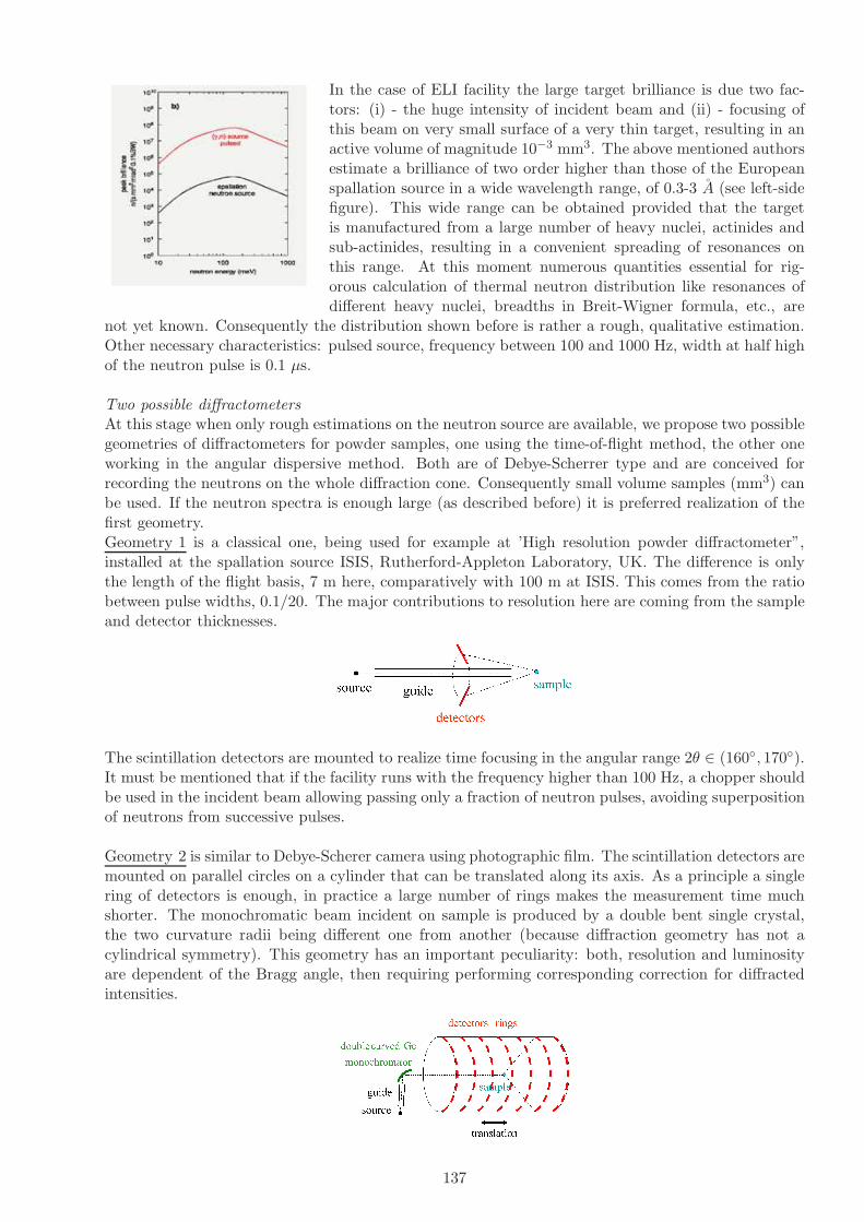
In the case of ELI facility the large target brilliance is due two fac-tors: (i) - the huge intensity of incident beam and (ii) - focusing ofthis beam on very small surface of a very thin target, resulting in anactive volume of magnitude 10−3 mm3. The above mentioned authorsestimate a brilliance of two order higher than those of the Europeanspallation source in a wide wavelength range, of 0.3-3 A (see left-sidefigure). This wide range can be obtained provided that the targetis manufactured from a large number of heavy nuclei, actinides andsub-actinides, resulting in a convenient spreading of resonances onthis range. At this moment numerous quantities essential for rig-orous calculation of thermal neutron distribution like resonances ofdifferent heavy nuclei, breadths in Breit-Wigner formula, etc., are
not yet known. Consequently the distribution shown before is rather a rough, qualitative estimation.Other necessary characteristics: pulsed source, frequency between 100 and 1000 Hz, width at half highof the neutron pulse is 0.1 µs.
Two possible diffractometersAt this stage when only rough estimations on the neutron source are available, we propose two possiblegeometries of diffractometers for powder samples, one using the time-of-flight method, the other oneworking in the angular dispersive method. Both are of Debye-Scherrer type and are conceived forrecording the neutrons on the whole diffraction cone. Consequently small volume samples (mm3) canbe used. If the neutron spectra is enough large (as described before) it is preferred realization of thefirst geometry.Geometry 1 is a classical one, being used for example at ’High resolution powder diffractometer”,installed at the spallation source ISIS, Rutherford-Appleton Laboratory, UK. The difference is onlythe length of the flight basis, 7 m here, comparatively with 100 m at ISIS. This comes from the ratiobetween pulse widths, 0.1/20. The major contributions to resolution here are coming from the sampleand detector thicknesses.
The scintillation detectors are mounted to realize time focusing in the angular range 2θ ∈ (160, 170).It must be mentioned that if the facility runs with the frequency higher than 100 Hz, a chopper shouldbe used in the incident beam allowing passing only a fraction of neutron pulses, avoiding superpositionof neutrons from successive pulses.
Geometry 2 is similar to Debye-Scherer camera using photographic film. The scintillation detectors aremounted on parallel circles on a cylinder that can be translated along its axis. As a principle a singlering of detectors is enough, in practice a large number of rings makes the measurement time muchshorter. The monochromatic beam incident on sample is produced by a double bent single crystal,the two curvature radii being different one from another (because diffraction geometry has not acylindrical symmetry). This geometry has an important peculiarity: both, resolution and luminosityare dependent of the Bragg angle, then requiring performing corresponding correction for diffractedintensities.
137
5.6.8 Dual-range Instrumentation for Wide Applicability Neutron Techniques
D Aranghel1, M.O.Dima1
1IFIN-HH, Bucharest, Romania
Based on the proposal for a brilliant pulsed neutron source with wavelengths in the range of 0.1-100angstrom at ELI we propose fostering the organisation of an Application Users Community centeredon dual-range (thermal and cold) neutron characterisation equipment.Given the work of the groupleader (Dr. Aranghel) on neutron scattering experiments in Berlin, Saclay and Julich (TOF andSANS experiments), this proposal will expand on those techniques to encompass both thermal andcold neutron applications. A brief view at the properties and suitability of the two energy ranges isindicated below.
• Thermal neutrons: (Wavelenght 1-3 angstrom Energy 10-100 meV) Investigations Atomic scalestructures; Fast dynamics; Low energy resolution;
• Cold neutrons: (Wavelenght 3 - 300 angstrom Energy 0.3 µeV-10 meV) Nano-scale structures;Slow dynamics; High energy resolution;
The group proposes therefore starting with known applications, for which there is in-group experience,and fostering the attraction of the broader scientific community in the areas below. This is in linewith the community-oriented goal of the ELI project itself:
• Bio-proteins / molecules: neutrons are an excellent hydrogen probe, with high H/D contrast.Applications are: function of protons in enzyme mechanisms (shuttling, transfer),D-labeled pro-teins in complex systems, proton-labels in deuterated systems, protein rigidity to D, proteininteraction and clustering, structures (membranes, single-lipid monolayers, bio-mat interfaces,etc), protein-folding mechanisms and dynamics, etc.Micron level beam-focusing envisaged at ELIis particularly attractive for this field.
• Nano-composites/porousites and Soft-matter: surfactants are of extreme importance in moderntechnology. Examples are (nano-particle) wetting of heat-transfer pipes in nuclear reactors, oilextraction from porousites (above 2/3 of world oil is in porousites), oil adhesion in engines,etchants in microtechnology photolithography, special paints for the naval industry, detergents,adhesives, emulsifiers, de/foamers, firefighting, ferro-fluids, dipalmitoylphosphati-dylcholine pre-vents alveoli from collapsing(atelectasis), etc. Although seemingly trivial in nature and functions,it cannot be stressed enough how important these substances are. Self-Assembled Monolayers(SAM-s) can be used as nano-templates for nano-patterning in alignment of single wall carbonnanotubes, dip-pen nanolithography, smart-surface functionalisation of biosensors (selective, hy-drophobicity based, protein affinity). SAM-s also have enormous potential in coatings as wettingcontrol, chemical resistance layers, bio-compatibility, molecular recognition and cell attachment,electrodes, bio-electronics, control of electron transfer, selective attachment nano-particle coat-ings (i.e. bio-compatible magnetic nano-particle blood disinfectation of fungus with magneticfiltering). This enormous pool of applications stands on surface-interaction physics, or neutronprobing in the range of q = 0.01 - 1 angstrom. Nano-porousites in turn are of interest for low-kmaterials in micro/nano-technology, for aerogels and xerogels in optics and printing industry (qrange: 0.01-0.1 ang.−1).
• Fullerenes, graphene: this is a class of materials still in the molecular structure studies stage (qrange: 0.1-1 ang.−1, thermal neutrons), however super-molecular compounds are appearing (suchas single-molecule electronics, thiole-connected), which cannot withstand large energy-kicks andrequire ultra-cold neutrons for in-situ dynamics investigations.
• Magnetic nano-materials: magnetic grains can be structurally and dynamics wise very wellunderstood with polarised neutrons (q = 0.01-0.1 ang.−1). Magnetic and domain rotation, spin-torque in ultra-thin film sandwiches occur in the 100 nm skin layer that can be investigated withvery-cold neutrons in back-scattering configuration (similar to the dedicated Brillouin LightScattering method, with the advantage of not probing and integrating all the magnetic layers).
138
• Hydrogen fuel cells: being the perfect proton-tracer, neutrons are useful in H-location (2%sensitivity with diffraction), H-bonding (0.1% with vibrational spectroscopy), Hdiffusion(0.1%with quasi-elastic scattering), H nano-structuring (0.01% with SANS), H density profiles (2%with reflectometry), etc.
As mentioned in the beginning, there would be a minimal start-up dual-range equipment, with thepossibility of further add-ons (or replacements) function of the community response or demands:1. Cold Neutron Spectrometer - this instrument would have variable resolution and would cover abroad range both in energy and momentum transfer. Its resolution and ample energy-momentumrange allow it to address a broad variety of scientific problems in biomaterials, polymer dynamics, bio-gels, interface physics, cements, nano-materials, rock characterisation, magnetic systems, quantumliquids, rotational tunneling spectroscopy, water dynamics, etc.2. Time-of-flight / Small-Angle Neutron Scattering Spectrometer - this instrument would examinesize, shape, internal structure and spatial aranjament of soft matter, coloidal systems, biologicalmacromolecules, pharmaceuticals, food science, respectively on a length nano and bio materials scale.It would follow a design similar to Sans2d (ISIS), or SASI (Argonne).
References
[1] Scientific Case for ELI Nuclear Physics http://www.eli-np.ro/executive-comittee-meeting-april-12-13.php;
[2] P. Boni, NIM A586, 1-8 (2008);
[3] ANL-05/42, Work-Shop Proc., Intense Pulsed Neutron Source Division Argonne Nat. Labs (2005).
139

5.6.9 An Intense BRIlliant Positron-Source produced via the (γ, e+e−) Reaction(BRIP)
D. Habs1, M. Gross1, P.G. Thirolf1, K. Schreckenbach2, C. Hugenschmidt2 and G. Dollinger3
1 Ludwig-Maximilians University, Munich, Germany2 Physik-Department E21, Technische Universitat Munchen, D-85747 Garching, Germany3 University of the Bundeswehr, Munich (Germany)
Using an intense γ beam of 1013 photons/s with (2.5±0.5) MeV we propose to realize an intensemoderated positron beam of about 107e+/s via the (γ,e+e−) reaction. Using a Ne moderator weexpect an about tenfold increased moderation efficiency compared to W or Pt moderators [1]. Theintensity of this novel source is significantly weaker the presently most intense moderated positronsource NEPOMUC at the Munich neutron source FRM 2 with about 9 · 108e+/s [2], where about1016γ/s from neutron capture hit the inner converter volume. Due to the small diameter and well-directed γ beam we expect for the new source a brilliance of 107e+/[s(mm mrad)2 0.1%BW], which isabout 4 orders of magnitude more brilliant than the NEPOMUC source. Using fully polarized γ beamsfor the first time we will obtain an intense, fully polarized positron beam, which can be transportedthrough beamlines via solenoidal fields to different detector systems [3]. Presently, we have a pulsedsource with 120 Hz repetition rate and a peak intensity for the 200 ns long pulses of 5 · 1011/s. Thesemacropulses consist of 100 micropulses each with 2 ns spacing and 2 ps duration. Frequently pulsedpositron beams are requested and one can improve the energy resolution of the positron beam by usinga time dependent acceleration field. It is clear that significant improvements of the positron sourceare expected, when the γ is upgraded in a second phase to 1015γ′s/s ans much higher repetition rate.Also presently the brilliance of the positron beam can be improved by remoderation by a factor of 103,while at the same time the intensity is reduced by a factor of 10–15 [4]. Low-energy positron beamsare used in fundamental physics studies of the properties of positronium (Ps), Ps− or more complexelectron-positron systems. In applied physics studies with positron beams of Fermi-surfaces, defects,interfaces etc. offer excellent diagnostics tools. The new brilliant source is best suited for micro-positron beams, e.g. in positron microscopy. Polarized positron beams open up a totally unexploredresearch area, where polarized electrons in e.g. magnetic structures can be studied.
References
[1] A. P. Mills and E.M. Gullikson, Appl. Phys. Lett. 49, 1121 (1986).
[2] C. Hugenschmidt et al., NIMA 593, 616 (2008).
[3] C. Hugenschmidt et al., NIM A 554, 384 (2005).
[4] C. Piochacz et al., Appl. Surf. Sci. 255, 98 (2008).
5.6.10 Intense BRIlliant Positron-Source: Positrons in Applied Physics
F.Constantin1, P.M.Racolta1, I. Vata1, E. Ivanov1
1 IFIN-HH, Bucharest, Romania
Using the BRIlliant Positron-Source, a part of the produced positrons will be diverted into a PositronGun facility which will enable high sensitivity measurements in applications of positron annihilationspectroscopy. The moderated positrons will be reaccelerated in the range of 0.8–50 keV and thenfocused on the target under study [1].The beam line will have to steer the mono-energetic positrons far away in order to eliminate the noiseof random gamma radiation. A typical coincidence setup, under high vacuum, will permit the studiesof various materials, concerning defects (crystals), free volumes (polymers) and also to perform a deepprofiling analysis. Experimental setups and results have already been realized in IFIN-HH using a22Na positron source, 10µCi, deposited on thin aluminized Mylar. The positron source is sandwiched
140
between the targets on the study and the coincidence gammas are recorded by two HPGE detectors;the acquisition system is a VME CAEN and the software is custom developed in our laboratory.Studies have been conducted on Aluminum and polymers [2].On the another hand using high intensity positron bursts, thin film of porous silica will be implantedand Ps and Ps2 will be created on the internal pore surfaces; the molecule formation occurs muchmore efficiently in the confined pore geometry. The Ps2 molecule will lead the way for further multi-positronium work and Positronium chemistry. Using a more intense positron source, we expect toincrease the Ps density to the point where many thousands of polarised Ps atoms will interact andundergo a phase transition to form a Bose Einstein condensate. The time evolution of dense Pssystem interacting with the pores or different molecules will be measured the time distribution of o-Ps annihilation togheter the o-Ps polarization being the main physical parameters characterising thesystem. The o-Ps polarization and the interaction of the o-P atoms with different kinds of moleculescan be measured by a conventional Time Differential Perturbed Angular Correlation applied to observethe anisotropy oscillation in the 3-gamma annihilation decay of polarised Psoitronium [3] and otherPAS methods.
References
[1] A. Vasilescu, L. Craciun, I. A. Ghita, O. Constantinescu, F. Constantin, C. Chiojdeanu, C. N.Zoita, A. Kiss, D. Bojin and P.M. Racolta Status of an R&D project of a Positron Gun at HoriaHulubei NIPNE Bucharest Applied Surface Science 255 (2008) 46–49
[2] F. Constantin, L. S. Craciun, O. Constantinescu, I. A. Ghita, C. Ionescu, P. M. Racolta, M.Straticiuc, A. Vasilescu, V. Braic, C. Zoita, A. Kiss, D. Bojin Status and Perspectives for a SlowPositron Beam Facility at the HH—NIPNE Bucharest AIP Conf. Proc. – March 10, 2009 – Volume1099, pp. 960-964
[3] ] E. Ivanov, I. Vata, D. Dudu, I.Rusen and N. Stefan, Quantum beats in the 3-gamma annihila-tion decay of Positronium observed by perturbed angular distribution. Appliedf Surface Science255(2008) 179-182
5.6.11 Positron-excited Auger Electron Spectroscopy (PAES)
C.M.Teodorescu1, A.M.Vlaicu1,C.Ghica1 and D.Macovei11 National Institute of Materials Physics, Bucharest-Magurele (Romania)
The principle of PAES has been demonstrated in 1988 [1]. Low energy positrons (10 eV) createcore holes (3p in Ni or Cu) with a probability as high as 0.04, which yields a considerable signal/ background ratio for Auger electrons, unlike the conventional Auger electron spectroscopy (AES).Additionally, the achievement of a convenient signal in conventional AES requires the use of an electronbeam of considerable intensity, which may induce defects, enhanced surface reactivity, degrades organiccompounds, etc. The PAES basic process is the following: low-energy positrons implanted into thesample are scattered towards the sample surface and trapped either in surface defects or in surfacestates, then they annihilate either with valence or core electrons. Around 10−3 electrons are emittedfor an annihilated positron. PAES may be obtained with the same statistics as AES with the decreaseof the energy deposited in the sample by three orders of magnitude. The initial experiment [1] wascarried out with a flux of 104 positron/sec; nowadays, the available sources provide intensities of severalorders of magnitude higher. In 1990, the extreme surface sensitivity of PAES was demonstrated bythe dramatic reduction (by a factor of 4) of the Cu M2,3VV electrons induced by the adsorption of0.5 ML S/Cu(001) [2]. This effect is determined by two factors: (i) the positive charge nature ofthe positrons; (ii) the spatial displacement of the positron surface states away from the copper singlecrystal surface, induced by the adlayer. The detection of the Auger electrons in this experimentwas carried in coincidence with the photons generated by annihilation. The origin of this signaldamping was confirmed by positron wavefunction calculation. A few time later, a complete modelof ”corrugated mirror” [1] was proposed to calculate the positron states and their annihilation rates
141

with core electrons. Metal surfaces of Al, Ni, Cu, and Au gave values of 1-5 % for these annihilationrates. For low Miller index surfaces, around 80 % of the positrons are annihilated with electrons fromthe topmost layer. The PAES decrease in intensity in the case of overlayer adsorption is stronglydependent on the impurity localization on the surface or in subsurface states. The simulations showthat most elements exhibit detectable PAES signals, if the corresponding binding energy (BE) of thelevel from which the electron becomes annihilated is lower than 100 eV. The annihilation probabilitywith a core electron has a dependence approximated as BE−1, with a probability of about 1 % for BE =100 eV and 0.05 % for BE = 500 eV [3]. The only comparable surface sensitive technique is low energyion scattering (LEIS). But LEIS also may lead to sample degradation or sputtering. In turn, PAES isnon-destructive. One of the limitations of PAES is that it cannot operate at high temperatures, sincethe positron is formed, which escapes from the surface, as evidenced by γ-ray spectroscopy [4]. Onemight expect that the remarkable intensity of positron beams that may be achieved at ELI-NP allowsPAES investigations of Auger electrons involving deeper levels, such as O KLL (510 eV), C KLL (275eV), N KLL (389 eV); this, together with the dramatic reduction in sample degradation and withthe extreme surface sensitivity opens new analysis possibilities for all organic compounds, adsorbates,in situ assessment of surface and interfaces processes in catalytic processes, etc.Other phenomena already evidenced are: the extreme sensitivity (0.02 ML) for the transition betweenthe positron localization in the neighbourhood of the Cu(001) surface or pushed away by adsorbedatoms for Cs/Cu(001), a phenomenon which takes place for about 0.7 ML adsorbed [5]. In some cases,the positron localization prior to their annihilation shows an extremely high chemical selectivity, asin Au/Cu(001), where a noticeable signal (∼ 40 % from the signal corresponding to one ML ofAu) is provided by a low quantity (0.07 ML of Au adsorbed at the surface) [6]. The completetheory of positron localization in solids, in the vicinity of defects, surfaces or interfaces, shows, also,a pronounced chemical sensitivity [7]. These facts promoted, after some years, the setting up of afacility dedicated to low-energy positron production and of associated techniques NEPOMUC nearMunich which provides nearly 109 positrons/sec. at 1 keV [8], whereas the first experiments implyingthe study of semiconductor surfaces [Si(001)] and of first ultrathin metallic layers on semiconductors[Cu/Si(001)] were immediately reported [9]. Perhaps not surprisingly, the first real experiments ofsurface and interface physics ever conducted in Romania concentrated on similar systems: metalsdeposited on Si(001), such as Fe/Si(001) [10].In the framework of the ELI-NP project, we intend to develop the PAES technique by using positronsyielded by ELI [11]. In addition to the methods described above, in the actual case the positron fluxshould exceed by several orders of magnitude the fluxes obtained with the actual sources. Thus, thePAES technique will be further developed. We intend to study also positron annihilation Auger elec-tron diffraction (PAED), by analyzing the angular distribution of the Auger electrons (angle resolvedPAES, ARPAES). This method, coupled to the extreme high surface sensitivity of PAES, should allowaccurate determinations of the geometry of adsorbates and of intimate details of reconstructed surfaceand interface geometries [12].Another advantage provided by ELI-NP is the possibility of working with positron pulses of ultralowduration (ps), which makes it possible the achievement of coincidence experiments positron/electron,positron/ etc.A modern surface and interface physics facility dedicated to positron annihilation related techniqueswill be implemented (Fig. 50), comprising:- ultrahigh vacuum (UHV) chamber with pumping system, ports, sample manipulator with polar andazimuthal motion, load-lock, storage chamber, etc.;- hemispherical electron energy analyzer, low angular acceptance, high brilliance;- angle-integrated electron energy analyzer, high intensity, cylindrical mirror analyzer (CMA);- electron time-of-flight analysis system;- an electron gun for simultaneous achievement of AES experiments;- a γ spectroscopy detector system, together with the required measurement chain for coincidencemeasurements (positron/γ, positron/electron, positron/electron/γ);- 4 evaporators;- one magnetron sputtering source;- one plasma discharge source;
142

- ion gun for sample sputtering;- quadrupole mass spectrometer for residual gas analysis, adsorption/desorption experiments.
Figure 50: Experimental setup for PAES and ARPAES, together with a schematics of the multi-coincidence technique.
The detection methods or stipulated analyses will be:- positron annihilation Auger electron spectroscopy (PAES);- angle-resolved PAES (ARPAES);- (AR)PAES obtained with coincidences γ - electron;- (AR)PAES obtained with coincidences positron-electron;- multi-coincidence methods positron - γ - electron, where for instance binding energies of positronsurface states may be obtained etc.- conventional Auger electron spectroscopy (AES); however, its integration in the proposed facilitywill allow a direct comparison of AES and PAES.
References
[1] A. Weiss, R. Mayer, M. Jibaly, C. Lei, D. Mehl, K.G. Lynn, Phys. Rev. Lett. 61, 2246 (1988).
[2] D. Mehl, A.R. Koymen, K.O. Jensen, F. Gotwald, A. Weiss, Phys. Rev. B 41, 799 (1990).
[3] K.O. Jensen, A. Weiss, Phys. Rev. B 41, 3928 (1990).
[4] R. Mayer, A. Schwab, A. Weiss, Phys. Rev. B 42, 1881 (1990) ; E. Soininen, A. Schwab, K.G. Lynn,Phys. Rev. B 43, 10051 (1991).
[5] A.R. Koymen, K.H. Lee, D. Mehl, A. Weiss, K.O. Jensen, Phys. Rev. Lett. 68, 2378 (1992).
[6] K.H. Lee, G. Yang, A.R. Koymen, K.O. Jensen, A. Weiss, Phys. Rev. Lett. 72, 1866 (1994).
[7] M.J. Puska, R.M. Nieminen, Rev. Mod. Phys. 66, 841 (1994).
[8] C. Hugenschmidt, K. Schreckenbach, M. Stadlbauer, B. Strasser, Nucl. Instrum. Meth. Phys. Res.A 554, 384 (2005) ; ibid Phys. Rev. B252, 3098 (2006).
143
[9] C. Hugenschmidt, J Mayer, K. Schreckenbach, Surf. Sci. 554, 2459 (2007).
[10] N.G. Gheorghe, G.A. Lungu, M.A. Husanu, Rom. Rep. Phys. , submitted (2010) ; N.G. Gheorghe,M.A. Husanu, G.A. Lungu, R.M. Costescu, D. Macovei, C.M. Teodorescu, Nanotech 2010 TechnicalAbstracts, accepted.
[11] ELI Scientific case, Secs. B V.6 and C II.2.
[12] A. Mascaraque, J. Avila, C.M. Teodorescu, M.C. Asensio, E.G. Michel, Phys. Rev. B. 55, R7315(1997) ; J. Avila, A. Mascaraque, C.M. Teodorescu, E.G. Michel, M.C. Asensio, Surf. Sci. 377-379, 856 (1997) ; M.G. Martin, J. Avila, M. Gruyters, C.M. Teodorescu, P. Dumas, Y.J. Chabal,M.C. Asensio, Appl. Surf. Sci. 123-124, 156 (1998).
5.6.12 Positron Annihilation Spectroscopy (PAS)
C.M.Teodorescu1, A.M.Vlaicu1,C.Ghica1 and D.Macovei11 National Institute of Materials Physics, Bucharest-Magurele (Romania)
Positron Annihilation Spectroscopy (PAS) represents a non-destructive method to characterize elec-tron structures, nature and concentration of defects (point defects and extended defects) in metals, al-loys, semiconductors, ionic crystals, amorphous materials. The method relies on the positron-electronannihilation with the emission of two γ quanta of 0.511 MeV each propagating in opposite directions.There are two ways of generating positrons and, therefore, two types of positron sources:
i. Radioactive isotope based source (22Na, 64Cu, 58Co and 68Ge) showing β+ decay (e.g. 22Na →22Ne + e+ + νe + γ(1.27MeV ))
ii. Sources based on e− - e+ pair generation, involving interaction energies ≥ 1.022 MeV. Suchsources may use the bremsstrahlung of a decelerated beam of MeV-electrons of a LINAC ontoa target (EPOS in Rossendorf, Germany; KEK in Tsukuba, Japan; AIST in Tsukuba, Japan;ANL in Argonne, USA; etc.), the γ radiation from a nuclear fission reactor (Delft, Holland) orthe γ radiation from a nuclear reaction of the kind 113Cd(n,γ)114Cd resulting in three gammaphotons with a total energy of 9.041 MeV which are used for the pair generation (Garching,Germany).
The positron lifetime in a solid depends on the local concentration of electrons. The lifetime of apositron captured in around an atomic vacancy is significantly longer than the lifetime of positronsin a matrix without structural defects. Based on this principle, one can detect and quantify thepresence of structural defects. In a crystalline material, such detectable defects may be atom vacancies,dislocations, planar defects. In amorphous materials, such as polymers, the detectable defects are thefree spaces between the polymeric chains.The γ photons emitted by the annihilation process are detected and analyzed using three differentspectroscopic techniques:
1. Positron Lifetime Spectroscopy - PALS. The technique currently applies in experimental set-upsusing 22Na sources where a 1.27 MeV γ photon is emitted in the same time with the e+. Thepositron lifetime is measured with respect to the β+ decay occurring with the emission of the1.27 MeV photon. The technique allows determining the concentration of defects such as singlevacancies, di-vacancies, clusters of vacancies or porosity in mesoporous materials. In the caseof a pulsed positron beam (LINAC based sources) the positron lifetime is measured as the timedifference between the 0.511-MeV photon and the machine pulse from timing system. Charac-teristic positron lifetimes in various materials vary from 0.1-0.5 ns in metals and semiconductors,to 0.5-5 ns in polymers and 1-100 ns in mesoporous materials, etc.
2. Angular Correlation of Annihilation Radiation - ACAR. The angle Θx,y between the γ photonsemitted in opposite directions is in general different from 180o and it depends on the transversalcomponents px and py of the electron momentum p with respect to the emitted γ photons (Θx,y
= px,y/m0c). The technique allows e.g. mapping of the Fermi surface in single crystals.
144

3. Doppler Broadening Spectroscopy - DBS. The energy of the emitted γ photons is slightly differentfrom 0.511 MeV and it depends on the longitudinal component pz of the electron momentump with respect to the emitted γ photons (0.511 MeV ± ∆E, with ∆E = pzc/2). Samples withhigh defects content induce a narrowing of the 0.511 MeV spectral line. The technique allowsgetting information on the electron momentum in the sample. By analyzing the line profile,two parameters are determined, S and W, corresponding to annihilation processes with valenceelectrons and core electrons, respectively. For a better signal/background ratio, especially on thewings of the spectral line (W parameter), the set-up with two detectors operated in coincidencemode is used - Coincidence Doppler Broadening Spectroscopy (CDBS).
The energy spectrum of the emitted positrons is generally wide, reaching several hundreds of keV (e.g.22Na delivers e+ with energies up to 540 keV). Before annihilation, positrons arrived inside the sampleare thermalized in a layer with a thickness of the order 102 µm. Therefore, the extracted structuralinformation results from a material layer with a thickness of only a few hundreds of µm next to thesurface. In cases where information from the whole sample volume is of interest (thickness of the orderof cm), another experimental variant is used, known as Gamma-induced Positron Spectroscopy (GIPS).In this configuration, a γ beam is directed towards the sample, generating e−-e+ pairs right insidethe sample (EPOS facility, Germany). The type of positron spectroscopy to be developed depends onthe characteristics of the positron source. In the case of the lifetime spectroscopy (PALS), the timebetween two consecutive positrons must be much longer than the maximum lifetime to be detected.This condition limits upwards the activity of a positron source based on radioactive isotopes. Thus,in order to be able to measure lifetimes of the order of 0.5 ns (semiconductors), the source activityshould not surpass 9x10⁵ Bq (1 Bq = 1 disintegration/sec), which is equivalent to a repetition rate of0.9 MHz. For lifetimes of the order of 102 ns, the source activity should be less than 2x10⁵ Bq, theequivalent of repetition rates less than 0.2 MHz in the case of a pulsed source. On the other hand,there are a series of disadvantages when using low frequency pulsed sources (LINAC), such as lowcounting rate, low signal/noise ratio.
There are several constructive solutions of the positron annihilation spectrometers adopted worldwide:• NEPOMUC at FRM-II in Garching (Munchen), Germany- γ source = nuclear reactor; 5 beamlines: Lifetime; CDBS; PAES; positron microscope- 5x10⁸ e+/s - the highest positron flow at the moment• Argonne Project APosS, USA- γ source = Linac, 15.5 MeV, 0.1 mA, 60 Hz- under construction, estimated flow 3x10⁹ e+/s• SOPHI Project in Saclay, France- γ source = Mini LINAC: 6 MeV, 300 Hz, 0.2 mA; 10 kW- under construction, estimated flow 108 e+/s• Positron Beam at IHEP Beijing, China- under construction; PALS, AMOC, CDBS- γ source = radioactive isotopes and LINAC• EPOS: ELBE Positron Source @ Research Centre Dresden Rossendorf, Germany- 40 MeV, 1 mA, 26 MHz repetition rate in cw mode; PALS, CDBS and AMOC with slow positrons- Gamma-induced Positron Spectroscopy for bulk samples
In our case, using the γ source of high-brilliance and high-energy represents a strong argument infavour of developing positron spectroscopy at ELI-NP. The γ-ray beam could be used eitherto form a positron beam or to generate e+-e− pairs inside the sample (GIPS variant). Although a finaldecision has not been taken as to what LINAC solution would be adopted at ELI-NP, in case thatthe parameters of the LINAC facility to be constructed in the ELI-NP are at least of the same orderof magnitude as the accelerator used at Argonne National Laboratory (APosS project), this will stillallow to develop the PALS and DBS positron spectroscopy at ELI-NP as it is previewed at ArgonneNational Laboratory.The utility of developing such spectroscopic techniques at ELI-NP consist in the first place in being
145
able to perform on-site characterization and diagnosis of materials and components involvedin the construction of the ELI-NP project itself. This method could be used in conjunction withthe other materials characterization techniques described as support tools for ELI-NP, the advantageof PAS consisting in the fact that it is a non-destructive method and it allows for investigations onbulk samples.
References
[1] Defects in silicon after B+ implantation: A study using a positron-beam technique,Rutherford backscattering, secondary neutral mass spectroscopy, and infrared absorp-tion spectroscopy, S. Eichler, J. Gebauer, F. Borner, A. Polity, R. Krause-Rehberg, E. Wendler,B. Weber, W. Wesch, H. Borner, Phys. Rev. B 56, 1393-1403 (1997).
[2] R. Krause-Rehberg, H. S. Leipner, Positron annihilation in Semiconductors, Springer-Verlag, New York, (1998).
[3] P. Coleman, Positron Beams and their applications, World Scientific, (2000).
[4] M. Charlton, J.W. Humbertson, Positron Physics, World Scientific, (2001).
[5] Positron annihilation spectroscopy in materials structure studies, V. I. Grafutin, E.P. Prokopiev, Physics - Uspekhi 45, 59 - 74 (2002).
[6] Ortho-positronium lifetime measurement - positron source activity and statistics,S. Thraenert, E.M. Hassan, R. Krause-Rehberg, Nuclear Instruments and Methods in Physics Re-search B 248, 336-339 (2006).
[7] Progress of the EPOS project:Gamma-induced Positron Spectroscopy (GiPS),R. Krause-Rehberg, W. Anwand, G. Brauer, M. Butterling, T. Cowan, A. Hartmann, M. Jung-mann, A. Krille, R. Schwengner, A. Wagner, Phys. Status Solidi C 6, 2451-2455 (2009).
[8] Experimental elucidation of vacancy complexes associated with hydrogen ion-inducedsplitting of bulk GaN, O. Moutanabbir, R. Scholz, U. Gosele, A. Guittoum, M. Jungmann,M. Butterling, R. Krause-Rehberg, W. Anwand, W. Egger, P. Sperr, Phys. Rev. B 81, 115205(2010).
146

5.6.13 AGPAS technique with high energy gamma beams
Gh.Cata-Danil1, A.M.Popovici11 University POLITEHNICA of Bucharest (Romania)
Accelerator-based Gamma-induced Positron Annihilation Spectroscopy (AG-PAS) [1, 2] is a new ex-perimental technique that employ positron annihilation spectroscopy by using MeV gamma-rays togenerate positrons instead of using radioactive or neutron-induced positron sources. This method openthe possibility of probing residual stress in thick materials by Doppler broadening measurements [3]reflected in the line shape parameters of the 511 keV annihilation peak.The range of keV positronsin materials are in the order of few hundred micrometers and hence the depths in materials thatcan be investigated by positrons are limited to this range. Therefore, standard positron annihilationtechniques are not appropiate to study defects in thick materials. With the new technique, the firstmeasurements of AG-PAS were conducted by using bremsstrahlung radiation from an electron Linacto perform Doppler spectroscopy of positron annihilation. In those measurements residual stresses inthick materials are reflected in the narrowing of the Doppler broadening of the 511 keV peak and inan increase of the annihilation fraction with valence electrons. Since positron lifetime spectroscopyis a usefull instrument to study in details different types of defects, such as dislocations and vacancyclusters [3], it is extremly important to adapt enable positron lifetime measurements in AG-PAS. Inreferences [1–3] Idaho group developed AG-PAS by using proton beams from accelerator to generategamma rays used both for coincidence measurement and to generate positrons inside thick materials.At ELI-NP high briliance gamma source appears a natural technical environment to apply AG-PASmethod. The laser pulse used for Compton backscattering could provides a start signal for the positronlifetime spectrometer and the stop signal is given by the detection of one of the two 511 keV photons.The recorded positron lifetime spectrum depends on the electron densities and hence provides infor-mation about the size of open volume defects. The method enables positron lifetime measurements inthick engineering materials up to tens of gm/cm2, a thickness not accessible by conventional positronlifetime spectroscopy.A strong point of the positron annihilation techniques is their unique ability todistinguish between different kinds of open volume defects and identify the defect size and its concen-tration in a single measurement. ELI-NP facility by its gamma source tunable in energy will allowto develop precise measurements in large volume samples, by recording data for the same sample atdifferent gamma energies.
References
[1] F. A. Selim et al., Stress Analysis Using Bremsstrahlung Radiation, accepted to be published inAdvances in X-ray Analysis, Vol. 46, proceedings of the 51 Denver Xray Conference, 2002
[2] F.A. Selim et al., Nucl. Inst. and Meth. B 192 (2002), p. 197
[3] F. A. Selim, D. P. Wells, J. F. Harmon, J . Kwofie, A. K. Roy, Applications of Electron Linacsin Stress and Defect Measurements, accepted to be published in proceedings of ANS meeting inAccelerators Applications in Nuclear Renaissance, 2003
147

5.6.14 Testing of radiation effects on commercial optical fibers
BConstantinescu1
1 IFIN-HH, Bucharest, Romania
Radiation effects on commercial optical fibers must be characterize at all telecommunication windowsbecause their behaviors are very important for space, military and civil agencies. Optical fibersare also good candidates for use in harsh environments like those encountered in Laser Megajouleor International Thermonuclear Experimental Reactor (ITER) facilities. Various types of opticalfibers have very different behaviors when expose to pulsed X-rays, neutrons or gamma rays, the samemain macroscopic changes being responsible for transmitted signal degradation: the radiation-inducedattenuation (RIA) and the radiation-induced luminescence (RIL). The generation of point defects inthe silica-glass matrix ( pure or doped) is at the origin of RIA and RIL. The optical properties,concentrations and the stability of the induced defects govern the RIA and RIL levels and recoverykinetics. Using IR-UV spectrometers, pulsed X-rays (or synergetic X + neutrons) irradiations allowsuch studies especially focused on defects recovery kinetics in the internal between pulses.
References
[1] S.Girard, D.L. Griscom, J. Baggio, B. Brichard, F. Berghmans, Journal of Non-Crystalline Solids352, 2637 (2006)
[2] S.Girard, Y. Querdane, A. Boukenter, J.-P. Meunier, Journal of Applied Physics 99, 023104 (2006).
[3] D. Sporea, Adelina Sporea, B. Constantinescu, Fusion Engineering and Design 74, 763 (2005).
[4] B. Constantinescu, R. Bugoi, E.R. Hodgson, R. Vila, P. Ioan, Journal of Nuclear Materials 367-370,1048 (2007).
5.6.15 Materials research in high intensity radiation fields
C.M.Teodorescu1, A.M.Vlaicu1,C.Ghica1 and D.Macovei11 National Institute of Materials Physics, Bucharest-Magurele (Romania)
Interaction of the high power (> PW) laser radiation with the solid state matter produces specificeffects, not completely known, on the structure and composition of the irradiated materials. Thedetailed knowledge of these effects has a fundamental interest for understanding the material behaviourin extreme conditions of irradiation. On the other hand, study of the irradiation effects significantlyhelps to optimization of the materials and components operating in the laser beam. This kind ofresearch will have a novelty character at ELI-NP, in conditions of extremely high power and intensityof the laser radiation.Tens of fs PW laser pulses can generate local ultrahigh pressures, of tens Mbar up to Gbar, insidethe irradiated materials. Such mechanical shocks cause structural defects, compositional inhomo-geneities, local melting and fast recrystallization, phase transitions etc. The structural and compo-sitional changes under the laser radiation, or other types of radiation resulting from the laser-targetinteraction, are main reasons of the material degradation during the use in the laser beam. Investi-gation of the damage effects of the optical components, target support, secondary targets, radiationdetectors or walls of the reaction chambers will allow the improvement of their performances and theextension of their lifetime in conditions of severe irradiation. The research results could be very helpfulfor the design of other classes of materials, more resistant when working in extreme conditions. It isworth mentioning that NIMP has a long collaboration with CERN (RD48 and Rd50) in improvingthe radiation hardness of Si detectors used in LHC experiments. All the structural defects induced byirradiation with various radiation beams (gamma, electrons, positrons, protons, neutrons, etc.) canaffect the electronic properties of the materials, with direct impact on the macroscopic characteristicsof the various micro/optoelectronic components used in the experiments.
148
Structure and chemistry of the bulk or surface of the irradiated materials can be approached by suit-able techniques, like high-resolution transmission electron microscopy (HRTEM), scanning transmis-sion electron microscopy (STEM), X-ray diffraction (XRD), x-ray photoemission spectroscopy (XPS),electron paramagnetic resonance (EPR) etc. These techniques are currently applied at the NationalInstitute of Materials Physics (NIMP), at Bucharest-Magurele, with modern equipments and researchteams with a long experience in the material characterization. The research of the irradiation effectscould be therefore carried out at NIMP-Magurele, which would avoid additional investments withinthe ELI-NP Project for the corresponding equipment and space. The foreseen techniques for this kindof studies and the main capabilities of the NIMP equipments are briefly reviewed in the following.
High resolution transmission electron microscopy (HRTEM)Currently, the high resolution transmission electron microscope (HRTEM) equipped with analysis ac-cessories of high spatial and spectral sensibility and resolution (Energy Dispersive X-ray Spectroscopy- EDS, Electron Energy Loss Spectroscopy - EELS) represents a particularly powerful instrument formorphological, structural and compositional characterization of materials. At this time, NIMP ownsan analytical transmission electron microscope used for morphological and structural studies basedon diffraction contrast, as well as compositional determinations through EDS. Until the beginningof 2011, NIMP expects to acquire and begin operating a high-resolution analytical electron micro-scope able to provide information with sub 1 A resolution both at structural and compositional level.The microscope, which will be equipped with an spherical aberration correcting device for S-TEM(Scanning Transmission Electron Microscopy), will operate both in TEM and in STEM mode. Thepresence of this correction device allows the formation of a 1 A diameter electron probe, reaching aspatial resolution of 6 0.08 nm in STEM mode. Among the major equipment that will be installed onthe microscope column, we mention the EDS unit, which allows a compositional analysis with spatialresolution of 6 1 nm and the EELS unit with an energy resolution of approximately 0.1 eV, whichprovides both compositional analysis and the visualization of the spatial distribution of the analyzedchemical elements, going up to atomic spatial resolution using the EFTEM (Energy Filtered Trans-mission Electron Microscopy) technique. Obtaining this information requires specialized preparationtechniques for the samples to be investigated. Many of these sample preparation techniques alreadyexist at NIMP, and will be supplemented with the acquisition of a dual FIB-SEM system until thebeginning of 2011.The transmission electron microscopy systems and the preparation techniques mentioned can be usedas part all three types of contributions by NIMP to the running of the ELI project given in the in-troduction. The current performances of high spatial and energetic resolution electron microscopesallow up to atomic precision for the determination and characterization of extended structural defects(dislocations, plane defects) and the associated deformation field [1–3] or compositional defects [4–6]resulting from radiation-solid type interactions in the experiments conducted at ELI. These investi-gations will also be necessary for characterizing the thin film targets that will be irradiated with thehigh power laser beam. In addition, the electron microscopy sample preparation techniques, based onprocessing with ion beams (classical ion thinning, the FIB technique), can be taken into considerationfor the purpose of preparing targets that consist of thin sheets of nanometer thickness.
X-Ray Diffraction (XRD)The structural properties of the materials exposed to extreme radiation fields can be further inves-tigated - before and after irradiation - by X-ray diffraction. Considering the specificity of variousX-ray diffraction techniques and the fact that the analysed samples can be provided in various states,shapes, and amounts, one should consider several setups for the X-ray diffractometers, or a multi-purpose diffractometer which can support several setups. Powder samples in large amounts requirea standard configuration, where the properties of the beam from a standard X-ray generator aretailored only by divergence slits. As the quantity of the sample of interest could decrease to smallselected amounts after the irradiation, enhancements in the detection system for parallel acquisitionare required, such as the use of stripe array detectors, X-ray CCD cameras, stacked detector, imagingplates etc.. In many cases however, the sample does not come in the form of powder which can bespread on a flat sample holder, but is attached to a substrate of various shapes. In such cases, the use
149

of incident monochromatic and parallel X-ray beam is required. X-ray multilayer focussing mirrorscan be additionally used to increase the incident beam intensity. The goniometer should allow sam-ple investigation at fixed incident grazing angle while scanning only the detector, and sample stageswith multiple orientation axes capabilities (Euler cradles). This setup which is adequate for largearea samples can be also used for reflectometry measurements in the case of large area flat samples.However, when the sample of interest decreases to very small areas, or when the mapping of a certainarea is required, the setup for X-ray diffraction require further beam tailoring in order to obtain pointfocus by capillary X-ray optics, and the detection system needs to record at once a solid angle of thediffracted beam by using X-ray CCD cameras or imaging plates. In such cases the standard X-raygenerator is replaced by rotating anode X-ray generators, and the costs of the setup and exploita-tion costs increase considerably. This setup can also allow in-plane diffraction and reciprocal spacemapping measurements. Recent X-ray diffractometers allow the reconfiguration of several setups ona single X-ray diffractometer unit, reducing the cost with respect to that of individual diffractometerunits. Given the variety of the required setups, it is usually difficult - financially and logistically - togather in one place all the required diffractometer setups.However, considering the availability of several setups of X-ray diffractometers in the close vicinity ofthe ELI-NP facility – National Institute for Materials Physics (NIMP), National Institute for Laser,Plasma and Radiation Physics (NILPRP), Horia Hulubei National Institute of Physics and NuclearEngineering (IFIN-HH), Institute for Microtechnology (IMT) – one can approach the X-ray diffractioninvestigations at these institutes.
X-ray photoelectron spectroscopy (XPS)X-ray photoelectron spectroscopy (XPS) is one of the most powerful methods of investigating the chem-ical states and composition of surfaces. This method is based on exciting a sample by a monochromaticX-ray beam obtained from a conventional X-ray source and analyzing the resulting photoelectrons asa function of their kinetic energy. This gives a distribution of electrons as a function of their bindingenergy for the initial levels. The main features of this techniques are: (a) compositional sensitivity,with a precision for determining compositions of the order of 0.1 %; (b) surface sensitivity due tothe photoelectron mean free paths of 0.5-1.5 nm; (c) chemical sensitivity through analysis of chem-ical shifts, which are of the order of 1-3 eV for most compounds; the resolution of current systemsbeing approximately 0.35 eV; (d) the possibility of conducting composition and/or chemical statedepth profiling, by combining XPS with controlled sample cleaning by ion (Ar+) bombardment; (e)for monocrystalline samples, angle-resolved XPS can determine structural characteristics with reason-able precision through X-ray photoelectron diffraction (XPD); (f) for very small binding energies, thecorresponding photoemission (ultraviolet photoelectron spectroscopy, UPS) allows the determinationof valence band state densities; (g) for monocrystals, angle-resolved UPS allows the determination ofdispersion laws in the valence band E(k).XPS spectroscopy and its associated techniques are very suitable for the study of surface modificationsas a result of the interaction with a high intensity laser beam. It is possible to analyze contamination,etching, surface alloying, layer removing. We intend to make available to the ELI community thephotoelectron spectroscopy expertise at NIMP, consisting of 3 systems, of which two are state-of-the-art, and a number of 11 specialists in this technique. The expertise mentioned is the most importantnationally, corresponding to approximately 50 % of the total national expertise for a single institution(NIMP).
Electron paramagnetic resonance (EPR)Electron paramagnetic resonance (EPR) spectroscopy represents a group of methods and experimentaltechniques that are used to detect species with unpaired electrons such as free radicals, transition metalions or point defects in materials, including colour centers or defects produced by irradiation. Theseare based on observing the absorption of microwaves (f > 1 GHz), which induce transitions betweenenergy levels in a magnetic field of non-zero spin electron systems in atoms/ions and molecules ineither free or solid state, as well as those of systems associated with point (atomic) defects in thecrystal lattices of solid materials.The following type of information is obtainable by EPR techniques: the nature, valence state, structure
150

and symmetry of the detected paramagnetic species, the potential presence of neighbouring defects, theconcentration, and the production mechanisms and their stability. Using such paramagnetic speciesas probes can also provide information about the host material, such as structure, local symmetry,lattice dynamics, and structural phase transition mechanisms.
References
[1] Strain mapping around dislocations in diamond and cBN, B. Willems, L.C. Nistor,C. Ghica, G. Van Tendeloo, Phys. Status Solidi A-Appl. Mat. 202, 2224 (2005).
[2] Characterization of 111 planar defects induced in silicon by hydrogen plasma treat-ments, C. Ghica, L.C. Nistor, H. Bender, O. Richard, G. Van Tendeloo, A. Ulyashin, Philos. Mag.86, 5137 (2006).
[3] TEM characterization of extended defects induced in Si wafers by H plasma treatment,C. Ghica, L.C. Nistor, H. Bender, O. Richard, G. Van Tendeloo, A. Ulyashin, J. Phys. D-Appl. Phys.40, 395 (2007).
[4] Atomic-scale study of electric dipoles near charged and uncharged domain walls inferroelectric films, C.-L. Jia, S.-B. Mi, K. Urban, I. Vrejoiu, M. Alexe, D. Hesse, Nat. Mater. 7,57 (2008).
[5] An Introduction to High-resolution EELS in Transmission Electron Microscopy,W. Grogger, F. Hofer, G. Kothleitner, B. Schaffer, Top. Catal. 50, 200 (2008).
[6] Column-by-column compositional mapping by Z-contrast imaging, S.I. Molina,D.L. Sales, P.L. Galindo, D. Fuster, Y. Gonzalez, B. Alen, L. Gonzalez, M. Varela, S.J. Penny-cook, Ultramicroscopy 109, 172 (2009).
151
![Bucharest-Magurele, Romania · arXiv:0705.2202v1 [quant-ph] 15 May 2007 Quantumdecoherenceand classicalcorrelations oftheharmonicoscillatorintheLindbladtheory A. Isar 1,2,(a) and](https://static.documents.pub/doc/80x56/5f75d952af531b531c27320e/bucharest-magurele-romania-arxiv07052202v1-quant-ph-15-may-2007-quantumdecoherenceand.jpg)

![[Bucharest] #DontTrustTheDarkSide](https://static.documents.pub/doc/80x56/58f138b31a28ab4e5d8b45b1/bucharest-donttrustthedarkside.jpg)


