35
The World Leader in High Performance Signal Processing Solutions Audio ADC/DACs Primer David Hossack
| Date post: | 22-Dec-2015 |
| Category: |
Documents |
| View: | 221 times |
| Download: | 1 times |
The World Leader in High Performance Signal Processing Solutions
Audio ADC/DACsPrimer
David Hossack
2
Goals
Learn about a real world signal processing applicationThere are hundreds of these in this room…..Also on DSP Board
Learn about commercial considerationsAsk
AgendaStart at actual A/D conversionMotivate sigma-delta modulatorMotivate interpolation and decimation filtersExample filters
No equations – simple overview
Ask questions

3
Audio Codec on DSKphysically large package by today’s standards
4
Analog/Digital Signal Conversion
Converting two things: Continuous Time <-> Discrete Time
Sampling Sample rate – samples/s or “Hz” – eg 44.1kHz or 48kHz
Need clock for discrete time Concern on clock jitter at interface between discrete-to-continuous
Continuous Value <-> Discrete Value Quantization
Number of levels or number of bits – eg 16bit or 24bit
These conversions can happen separately Eg Switched capacitor DAC
Digital (discrete time, discrete value) -> analog, discrete time
Continuous time, but still sampled -> analog, continuous time
Not necessarily a one-to-one transformation between input samples and output samples

5
Typical Specs for Audio Converters
SNR – measure of additive noise90-120dB“A-weighted”Bandwidth
20-20kHz THD – measure of errors at harmonics of input – nonlinearity
80-110dB
These are “AC” Specs
“Traditional” converter specs not appropriateAbsolute accuracyIntegral non-linearityDifferential non-linearityConversion Time

6
What does 100dB mean?
“CD quality” N= 16 bits => approx 6N + 2 => 98dB
With assumptions regarding the signal and error pdfs Flat weighting, full bandwidth
1 part in 100000 0.001%
Component matching on silicon 1% easy, with care :
0.1% >12 bits usually requires calibration or signal processing
Need to be careful to determine how errors manifest For audio:
Absolute accuracy is not important Linearity fairly important Noise very important
Hard to design audio converter using only component matching Sigma-Delta Modulation is a signal processing method to solve this Introduces its own problems
Oversampling Out of Band Noise Non-linear system that is hard to fully analyze
Errors Specs:•Offset•Gain•Linearity•Noise

7
Sigma Delta Modulation
Method for obtaining high resolution signal conversion without requiring high component matchingQuantizes input to small number of levelsSignal detail is preserved and obtaining by filtering
Requires signal processing Requires oversampling, requires sample rate conversion filters
ADC – decimation (downsampling with filtering)DAC – interpolation (upsampling with filtering)
Economics limited adoption until approx 1990Moore’s law allowed the DSP implementation to be cost effective
In engineering, the “rules” and constraints are always changingImplementations have changed significantly over the years
8
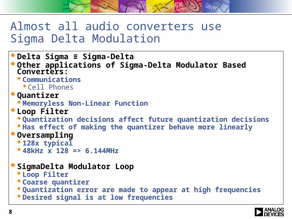
Almost all audio converters useSigma Delta Modulation Delta Sigma ≡ Sigma-Delta Other applications of Sigma-Delta Modulator Based Converters:
Communications Cell Phones
QuantizerMemoryless Non-Linear Function
Loop FilterQuantization decisions affect future quantization decisionsHas effect of making the quantizer behave more linearly
Oversampling128x typical48kHz x 128 => 6.144MHz
SigmaDelta Modulator LoopLoop FilterCoarse quantizerQuantization error are made to appear at high frequenciesDesired signal is at low frequencies

9
One bit vs Multi-bitIn the one-bit D/A converter, clock jitter in the over sampling clock translates directly into D/A errors - causing gross errors, increasing noise and reducing the sound quality.
In a multibit sigma-delta made up of multiple two-level D/A converters, the D/A output looks more like an analog signal, making it less sensitive to jitter and easier to filter.
10
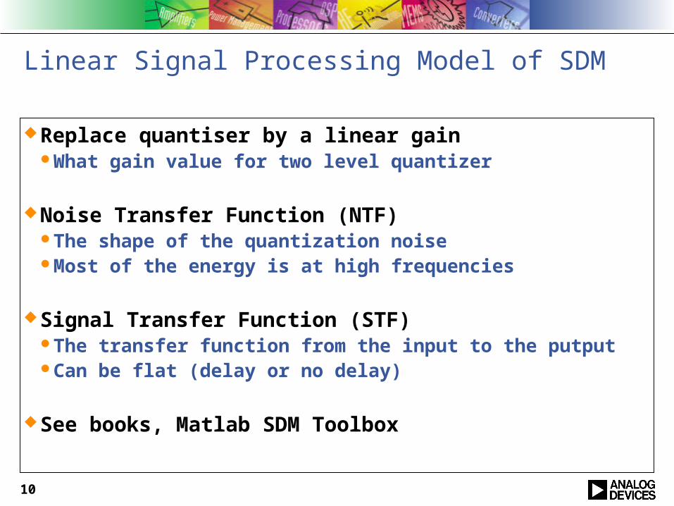
Linear Signal Processing Model of SDM
Replace quantiser by a linear gainWhat gain value for two level quantizer
Noise Transfer Function (NTF)The shape of the quantization noiseMost of the energy is at high frequencies
Signal Transfer Function (STF)The transfer function from the input to the putputCan be flat (delay or no delay)
See books, Matlab SDM Toolbox

11
Sigma-Delta DAC
Two Level DACNo matching problemsErrors are gain, offset
Horrible out of band noiseNon-linearities due to inter symbol interference and slew rate
limiting
Multilevel DAC
ImplementationsSwitched Capacitor
Continuous amplitude, discrete time filter Current Source

12
Multi Level DAC

13
SDM DAC Stages
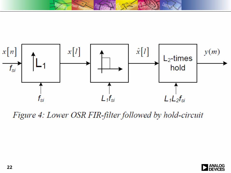
Digital Interpolation2x Interpolator
Upsample by 2 Halfband (FIR) Allpass based structure (IIR)
2x Interpolator Upsample by 2 Halfband (FIR) Allpass based structure (IIR)
CIC Interpolator Often Linear Interpolator Sinc2
Also need CIC compensation filter
Digital Sigma Delta ModulatorDigital Dynamic Element Matching
Also designed using sigma-delta techniquesAnalog DAC
128x
1x → 2x
2x → 4x
4x → 128x
→ 17 levels
→ 16 of 2 level
14
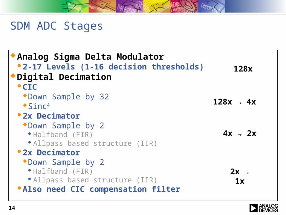
SDM ADC Stages
Analog Sigma Delta Modulator2-17 Levels (1-16 decision thresholds)
Digital DecimationCIC
Down Sample by 32Sinc4
2x DecimatorDown Sample by 2
Halfband (FIR)Allpass based structure (IIR)
2x DecimatorDown Sample by 2
Halfband (FIR)Allpass based structure (IIR)
Also need CIC compensation filter
128x
128x → 4x
4x → 2x
2x → 1x

15
CIC Filter
Recursive Filter Structure – yet FIRPole / Zero CancellationNeed to use modulo arithmetic
Efficient for Interpolation and Decimation Very good transfer function for large rate changes
Interpolator – images of signals near dc are suppressedDecimator – frequencies that will alias to near DC suppressed
Very simple implementation
Graphic from wikipedia
16
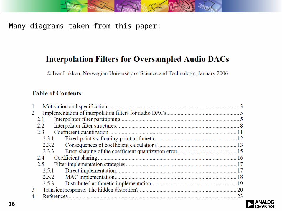
Many diagrams taken from this paper:

17

18
19

20
1:<>v(out) 2:<>v(out) 3:<>v(out)
-90
-80
-70
-60
-50
-40
-30
-20
-10
0
10
0 .2 .4 .6 .8 1 1.2 1.4 1.6 1.8 2 2.2 2.4 2.6 2.8 3frequency, Hertz
Component Responses – Continuous Coefficients
FIR1
FIR2
Sinc2

21
Digital Filter Implementation
Use CIC filters at higher sample ratesCost efficient structure for implementing restricted set of FIR filters
Use FIR/IIR Filters at lower sample ratesExploit structural symmetries
Eg Half band FIR interpolator uses input samples directlyEg Half-band or parallel all-pass filters
Restricted responsesCompensation required for CIC filters
CIC often implemented flatFIR/IIR usually implemented by a simple DSP engine
Fixed program – hardwired in logicSingle multiplier or multiplier equivalentEg Canonic Signed Digit / Signed Power of Two“multiplierless”Multiple channels implemented by single DSP engine
Cost/Power important – not on digital processEg 0.35u or 0.18u rather than say 65nm or 45nm for analog reasons
22

23

24
25
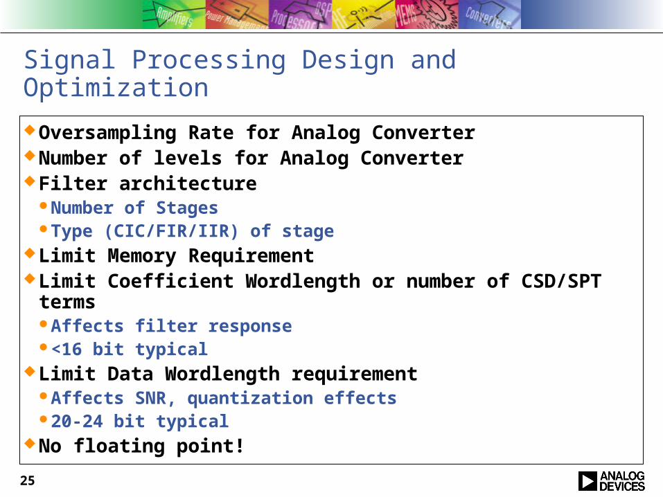
Signal Processing Design and Optimization
Oversampling Rate for Analog ConverterNumber of levels for Analog ConverterFilter architecture
Number of StagesType (CIC/FIR/IIR) of stage
Limit Memory RequirementLimit Coefficient Wordlength or number of CSD/SPT terms
Affects filter response<16 bit typical
Limit Data Wordlength requirementAffects SNR, quantization effects20-24 bit typical
No floating point!
26
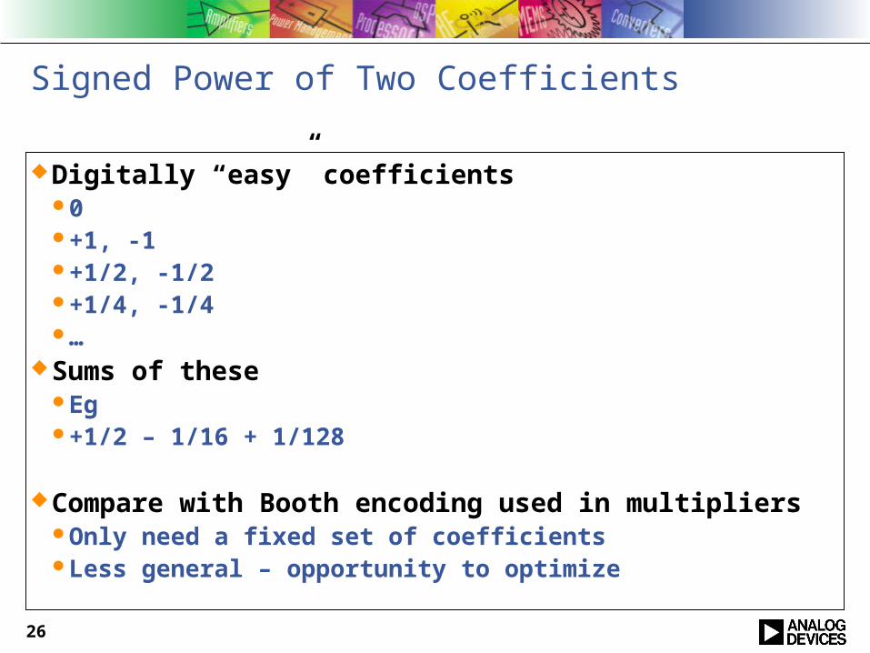
Signed Power of Two Coefficients
Digitally “easy” coefficients0+1, -1+1/2, -1/2+1/4, -1/4…
Sums of theseEg+1/2 – 1/16 + 1/128
Compare with Booth encoding used in multipliersOnly need a fixed set of coefficientsLess general – opportunity to optimize

27

28
A very simple DSP
One FIR tap calculated per clock cycle- Already have higher clock rate available
Two’s complement or SPT
24 bit Two’s complement
24 bit Two’s complement
24 bit Two’scomplement

29
1:<>v(out) 2:<>v(out) 3:<>v(out)
-90
-80
-70
-60
-50
-40
-30
-20
-10
0
10
0 .2 .4 .6 .8 1 1.2 1.4 1.6 1.8 2 2.2 2.4 2.6 2.8 3frequency, Hertz
Component Responses – Continuous Coefficients
FIR1
FIR2
Sinc2

30
5:<>v(out)
-90
-80
-70
-60
-50
-40
-30
-20
-10
0
10
0 .2 .4 .6 .8 1 1.2 1.4 1.6 1.8 2 2.2 2.4 2.6 2.8 3frequency, Hertz
Full Response with
Continuous Coefficients
31
6:<>v(out)
-90
-80
-70
-60
-50
-40
-30
-20
-10
0
10
0 .2 .4 .6 .8 1 1.2 1.4 1.6 1.8 2 2.2 2.4 2.6 2.8 3frequency, Hertz
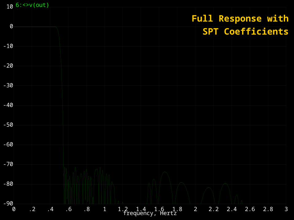
Full Response with
SPT Coefficients
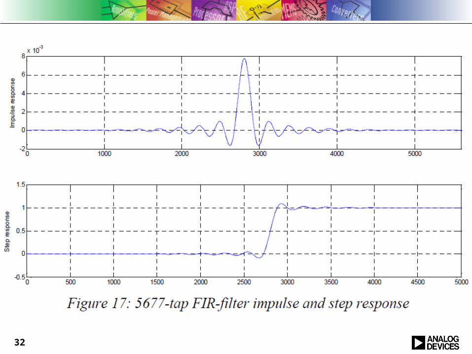
32

33
Gentler Frequency ResponseRequires higher sampling rate

34
Summary
Audio ADC and DAC is a rich example of real world signal processing
System / Architectural Level DesignUse digital technology to overcome weaknesses in analog
Filter Architectural DesignCIC vs FIR vs IIR
Filter OptimizationStructureWord lengths of coefficients and data
35
Presented By:David Hossack
Analog Devices, Inc.804 Woburn StreetWilmington MA 01887


