Thermal Combustor System Product PageThermal Combustor SystemThe Thermal Combustor System is a market driven answer to a unique set of vapor combustion air pollution control questions. Highly concentrated vent gas emissions are common within the natural gas processing and production, petro-chemical, and chemical processing, industries. These emissions are commonly low in volume but very high in concentration. Historically answers to these emissions challenges have included inefficient and dangerous flare technology . CPI brings to market our Thermal Combustor System as a much safer, more efficient, and more versatile abatement technology that is guaranteed to meet your air pollution control needs. Thermal Combustor SystemCatalytic Products International is continuing our 45 year history of providing innovative air pollution control solutions with a line of highly flexible, economical EPA qualified, vapor combustion systems. CPI’s Thermal Combustor Systems (TCS) routinely exceed all worldwide regulatory requirements while providing a level of sophistication that is unmatched in our industry. In today’s ever tightening regulatory climate, traditional technologies such as open flares and pit flares cannot achieve consistent high VOC destruction at an economical installed cost . Low cost - High Performance - Long Life are the key advantages of CPI’s Thermal Combustor Systems. Thermal Combustor Systems are designed to safely burn or combust hy drocarbon vapor mixtures. The TCS are widely flexible and can confidently handle the vent gas which may or may not be within the flammable range. The TCS provides an extraordinary level of safety when compared to traditional flaring systems . Our 45 year history of emissions abatement system design and manufact uring, assure you a saf e and reliable system. Thermal Combustor Systems are custom designed for your specific process and can include forced draft or a normally drafted system along with a full complement of auxiliary devices to aid in performance and safety.
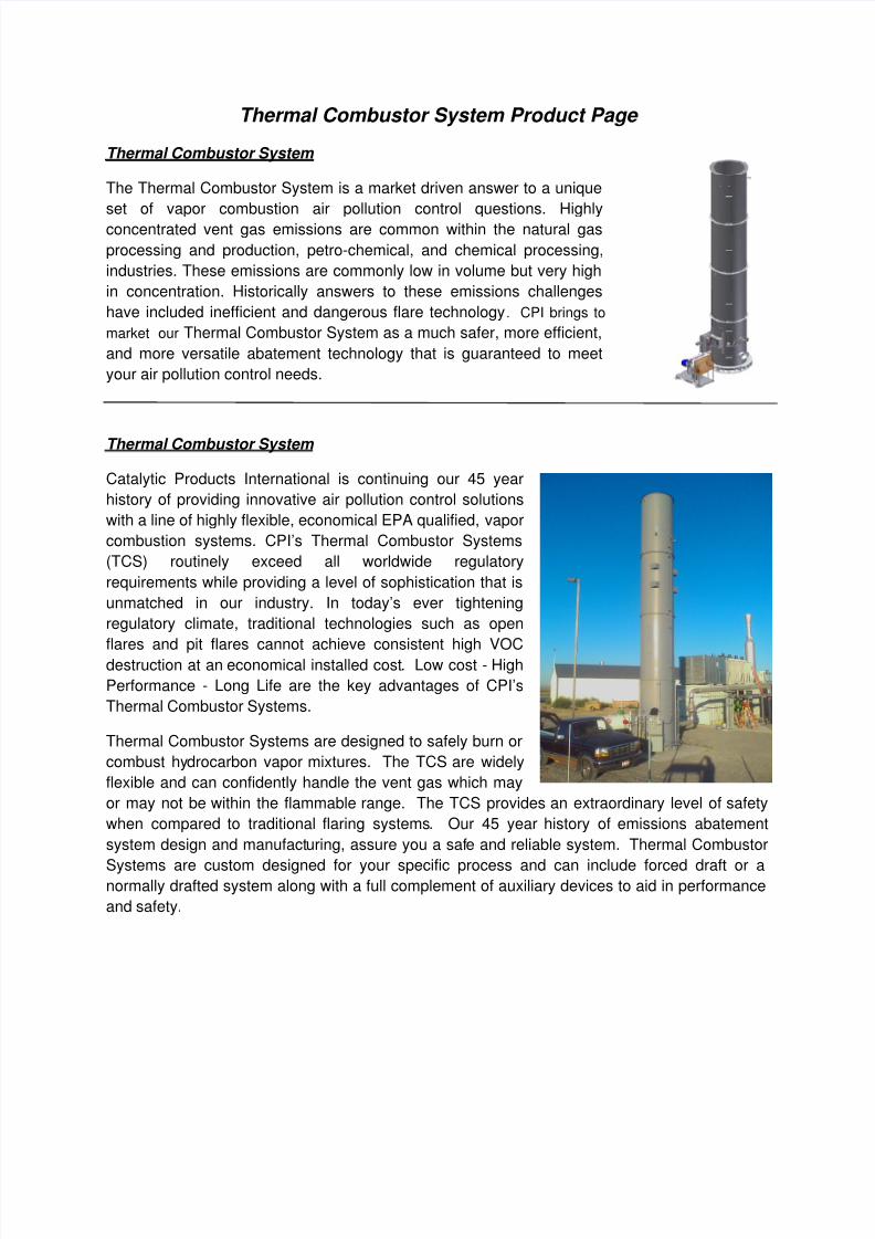
The Thermal Combustor System is a market driven answer to a unique
set of vapor combustion air pollution control questions. Highly
concentrated vent gas emissions are common within the natural gas
processing and production, petro-chemical, and chemical processing,
industries. These emissions are commonly low in volume but very high
in concentration. Historically answers to these emissions challenges
have included inefficient and dangerous flare technology. CPI brings to
market our Thermal Combustor System as a much safer, more efficient,
and more versatile abatement technology that is guaranteed to meet
your air pollution control needs.
Thermal Combustor System
Catalytic Products International is continuing our 45 year
history of providing innovative air pollution control solutions
with a line of highly flexible, economical EPA qualified, vapor
combustion systems. CPI’s Thermal Combustor Systems
(TCS) routinely exceed all worldwide regulatory
requirements while providing a level of sophistication that is
unmatched in our industry. In today’s ever tightening
regulatory climate, traditional technologies such as open
flares and pit flares cannot achieve consistent high VOCdestruction at an economical installed cost. Low cost - High
Performance - Long Life are the key advantages of CPI’s
Thermal Combustor Systems.
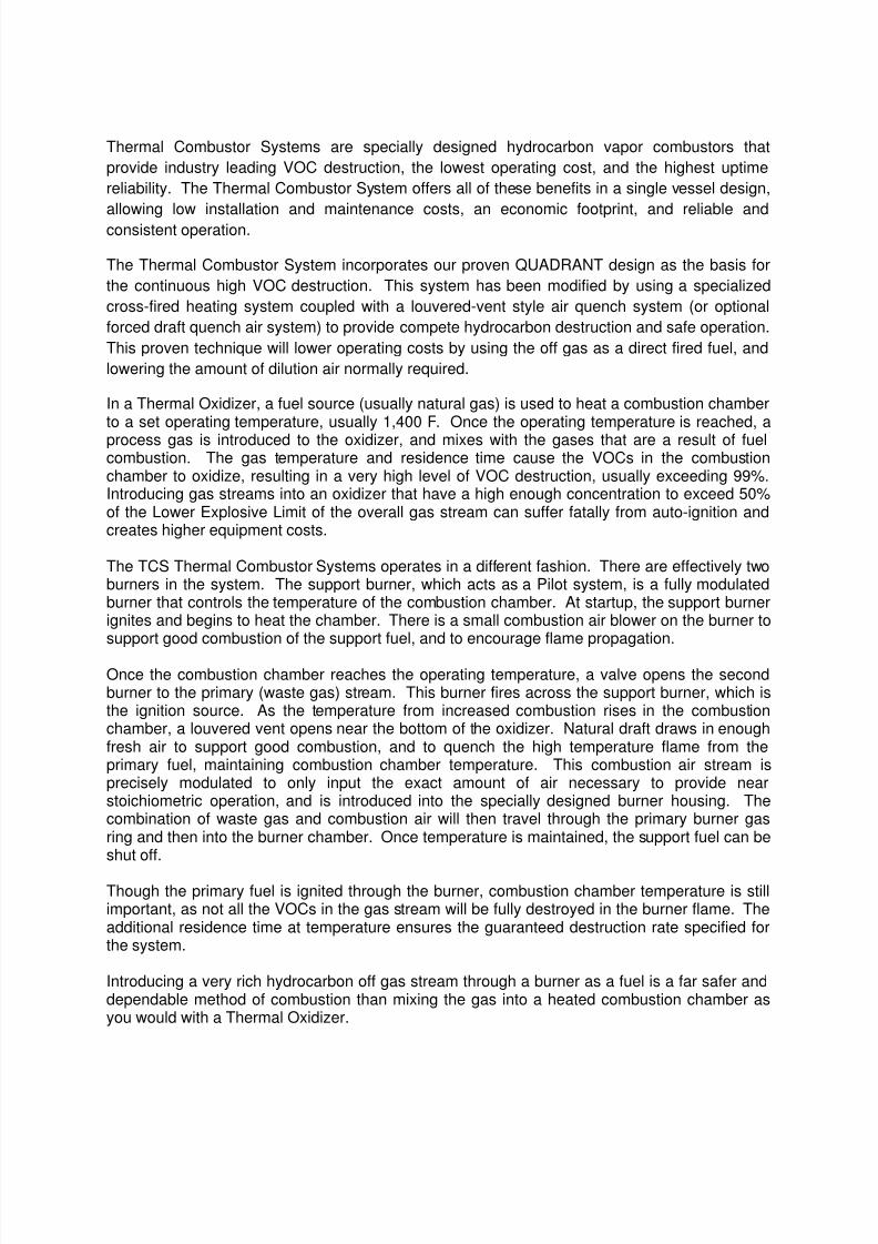
Thermal Combustor Systems are designed to safely burn or
combust hydrocarbon vapor mixtures. The TCS are widely
flexible and can confidently handle the vent gas which may
or may not be within the flammable range. The TCS provides an extraordinary level of safety
when compared to traditional flaring systems. Our 45 year history of emissions abatement
system design and manufacturing, assure you a safe and reliable system. Thermal Combustor
Systems are custom designed for your specific process and can include forced draft or anormally drafted system along with a full complement of auxiliary devices to aid in performance
Thermal Combustor Systems are specially designed hydrocarbon vapor combustors that
provide industry leading VOC destruction, the lowest operating cost, and the highest uptime
reliability. The Thermal Combustor System offers all of these benefits in a single vessel design,
allowing low installation and maintenance costs, an economic footprint, and reliable and
consistent operation.
The Thermal Combustor System incorporates our proven QUADRANT design as the basis for
the continuous high VOC destruction. This system has been modified by using a specialized
cross-fired heating system coupled with a louvered-vent style air quench system (or optional
forced draft quench air system) to provide compete hydrocarbon destruction and safe operation.
This proven technique will lower operating costs by using the off gas as a direct fired fuel, and
lowering the amount of dilution air normally required.
In a Thermal Oxidizer, a fuel source (usually natural gas) is used to heat a combustion chamberto a set operating temperature, usually 1,400 F. Once the operating temperature is reached, a
process gas is introduced to the oxidizer, and mixes with the gases that are a result of fuelcombustion. The gas temperature and residence time cause the VOCs in the combustionchamber to oxidize, resulting in a very high level of VOC destruction, usually exceeding 99%.Introducing gas streams into an oxidizer that have a high enough concentration to exceed 50%of the Lower Explosive Limit of the overall gas stream can suffer fatally from auto-ignition andcreates higher equipment costs.
The TCS Thermal Combustor Systems operates in a different fashion. There are effectively twoburners in the system. The support burner, which acts as a Pilot system, is a fully modulatedburner that controls the temperature of the combustion chamber. At startup, the support burnerignites and begins to heat the chamber. There is a small combustion air blower on the burner tosupport good combustion of the support fuel, and to encourage flame propagation.
Once the combustion chamber reaches the operating temperature, a valve opens the secondburner to the primary (waste gas) stream. This burner fires across the support burner, which isthe ignition source. As the temperature from increased combustion rises in the combustionchamber, a louvered vent opens near the bottom of the oxidizer. Natural draft draws in enoughfresh air to support good combustion, and to quench the high temperature flame from theprimary fuel, maintaining combustion chamber temperature. This combustion air stream isprecisely modulated to only input the exact amount of air necessary to provide nearstoichiometric operation, and is introduced into the specially designed burner housing. Thecombination of waste gas and combustion air will then travel through the primary burner gasring and then into the burner chamber. Once temperature is maintained, the support fuel can beshut off.
Though the primary fuel is ignited through the burner, combustion chamber temperature is stillimportant, as not all the VOCs in the gas stream will be fully destroyed in the burner flame. Theadditional residence time at temperature ensures the guaranteed destruction rate specified forthe system.
Introducing a very rich hydrocarbon off gas stream through a burner as a fuel is a far safer anddependable method of combustion than mixing the gas into a heated combustion chamber asyou would with a Thermal Oxidizer.
One of the key design features of The Thermal Combustor System is that the process
management does not require the use of complicated and slow reacting LEL measurement
equipment. Combustion air is precisely metered based on maintaining a combustion chamber
temperature. This simple innovation allows for fast response to fluctuating process gas
streams, consistent and accurate fuel use, use of process fuel only when sufficient values aredelivered, and lower capital, installation, and maintenance costs by eliminating the LEL
systems.
The complete system is supplied as an internally insulated vessel, designed to keep heat inside
and limit shell growth. The internally insulated design maintains all expansion properties for
long life, and lowers the installation costs since the system is pre-assembled, piped, and wired.
No other system in the industry can meet the advantages found in the Thermal Combustor
System.
TCS Operation
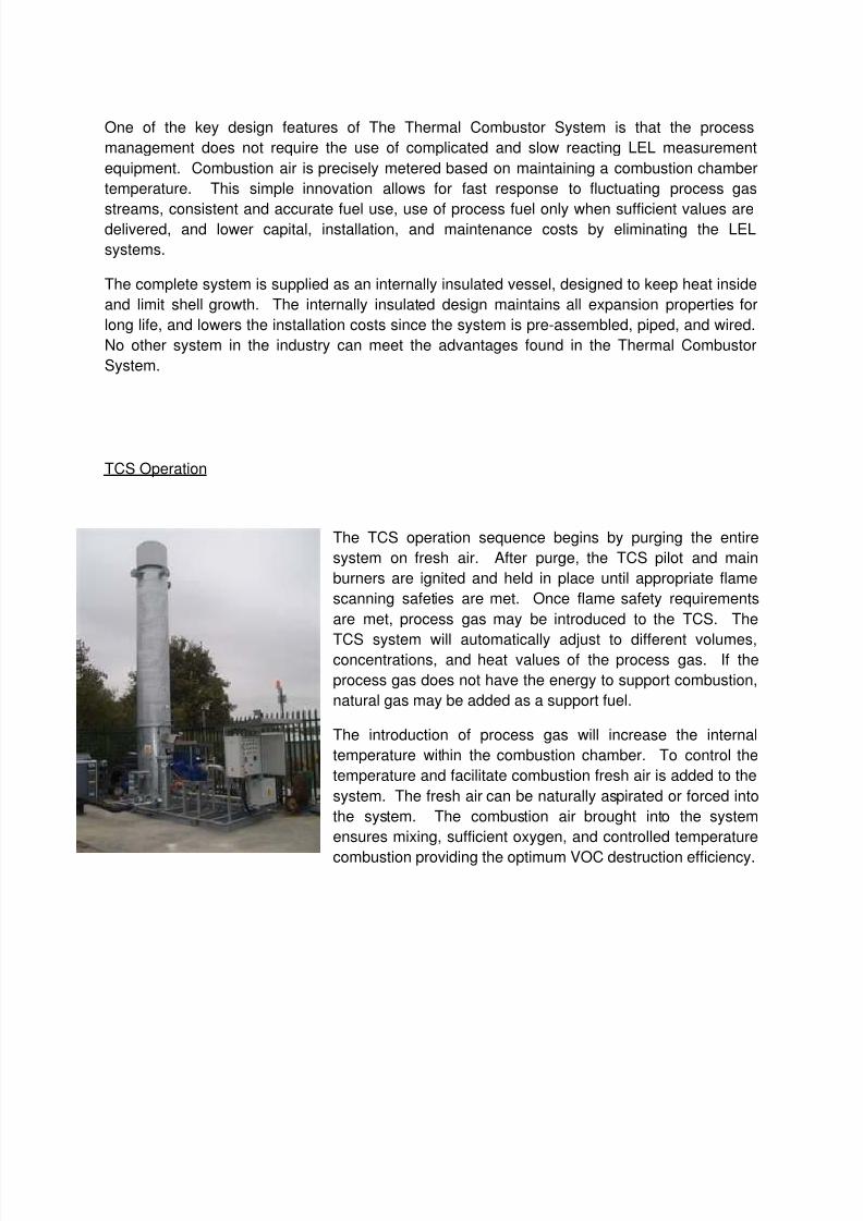
The TCS operation sequence begins by purging the entire
system on fresh air. After purge, the TCS pilot and main
burners are ignited and held in place until appropriate flame
scanning safeties are met. Once flame safety requirements
are met, process gas may be introduced to the TCS. The
TCS system will automatically adjust to different volumes,concentrations, and heat values of the process gas. If the
process gas does not have the energy to support combustion,
natural gas may be added as a support fuel.
The introduction of process gas will increase the internal
temperature within the combustion chamber. To control the
temperature and facilitate combustion fresh air is added to the
system. The fresh air can be naturally aspirated or forced into
the system. The combustion air brought into the system
ensures mixing, sufficient oxygen, and controlled temperature
combustion providing the optimum VOC destruction efficiency.
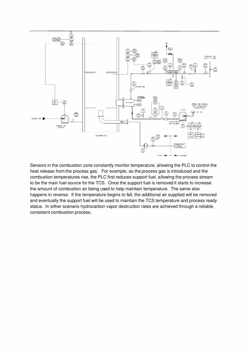
Sensors in the combustion zone constantly monitor temperature, allowing the PLC to control the
heat release from the process gas. For example, as the process gas is introduced and the
combustion temperatures rise, the PLC first reduces support fuel, allowing the process stream
to be the main fuel source for the TCS. Once the support fuel is removed it starts to increasethe amount of combustion air being used to help maintain temperature. The same also
happens in reverse: If the temperature begins to fall, the additional air supplied will be removed
and eventually the support fuel will be used to maintain the TCS temperature and process ready
status. In either scenario hydrocarbon vapor destruction rates are achieved through a reliable,
All Thermal Combustor Systems are fully enclosed designs that hides the flame while thermally
combusting the vapor gas steam. This supports a safe design when compared to exposed
flame flare systems and allows installation at numerous areas of any plant.
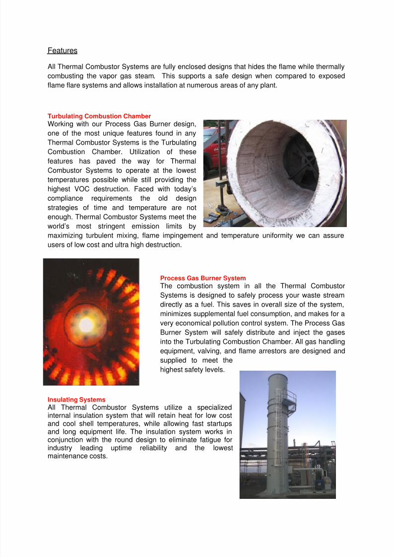
Turbulating Combustion Chamber
Working with our Process Gas Burner design,
one of the most unique features found in any
Thermal Combustor Systems is the Turbulating
Combustion Chamber. Utilization of these
features has paved the way for Thermal
Combustor Systems to operate at the lowest
temperatures possible while still providing the
highest VOC destruction. Faced with today’s
compliance requirements the old design
strategies of time and temperature are not
enough. Thermal Combustor Systems meet the
world’s most stringent emission limits by
maximizing turbulent mixing, flame impingement and temperature uniformity we can assure
users of low cost and ultra high destruction.
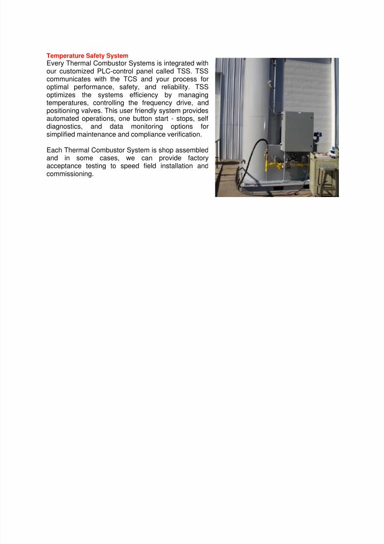
Process Gas Burner System
The combustion system in all the Thermal Combustor
Systems is designed to safely process your waste stream
directly as a fuel. This saves in overall size of the system,
minimizes supplemental fuel consumption, and makes for a
very economical pollution control system. The Process Gas
Burner System will safely distribute and inject the gases
into the Turbulating Combustion Chamber. All gas handling
equipment, valving, and flame arrestors are designed and
supplied to meet the
highest safety levels.
Insulating Systems
All Thermal Combustor Systems utilize a specializedinternal insulation system that will retain heat for low costand cool shell temperatures, while allowing fast startupsand long equipment life. The insulation system works inconjunction with the round design to eliminate fatigue forindustry leading uptime reliability and the lowestmaintenance costs.
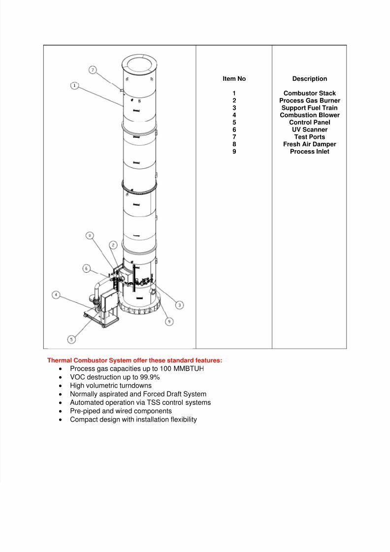
Every Thermal Combustor Systems is integrated withour customized PLC-control panel called TSS. TSScommunicates with the TCS and your process foroptimal performance, safety, and reliability. TSS
optimizes the systems efficiency by managingtemperatures, controlling the frequency drive, andpositioning valves. This user friendly system providesautomated operations, one button start - stops, selfdiagnostics, and data monitoring options forsimplified maintenance and compliance verification.
Each Thermal Combustor System is shop assembledand in some cases, we can provide factoryacceptance testing to speed field installation andcommissioning.