Page 1
HAL Id: hal-01395695https://hal.archives-ouvertes.fr/hal-01395695
Submitted on 29 Nov 2016
HAL is a multi-disciplinary open accessarchive for the deposit and dissemination of sci-entific research documents, whether they are pub-lished or not. The documents may come fromteaching and research institutions in France orabroad, or from public or private research centers.
L’archive ouverte pluridisciplinaire HAL, estdestinée au dépôt et à la diffusion de documentsscientifiques de niveau recherche, publiés ou non,émanant des établissements d’enseignement et derecherche français ou étrangers, des laboratoirespublics ou privés.
Thermal energy harvesting: thermomagnetic versusthermoelectric generator
Morgan Almanza, Alexandre Pasko, A. Bartok, Frédéric Mazaleyrat, MartinoLobue
To cite this version:Morgan Almanza, Alexandre Pasko, A. Bartok, Frédéric Mazaleyrat, Martino Lobue. Thermal en-ergy harvesting: thermomagnetic versus thermoelectric generator. 7th International Conference onMagnetic Refrigeration at Room Temperature (Thermag VII), Sep 2016, Turin, Italy. �hal-01395695�
Page 2
Seventh IIF-IIR International Conference on Magnetic Refrigeration at Room Temperature, Thermag VII
Torino, Italy, 11-14 September 2016
Thermal energy harvesting: thermomagnetic versus thermoelectric generator
M. Almanza(a)*, A. Pasko(a), A. Bartok(a), F. Mazaleyrat(a), M. LoBue(a)
(a) SATIE, ENS Cachan, CNRS, Université Paris-Saclay, 94235 Cachan, France *Corresponding author. E-mail: [email protected]
ABSTRACT
We compare the efficiency and the power density of thermoelectric and thermomagnetic generators at
maximum power. The performances of thermomagnetic generator are computed using an equation of state,
either extrapolated from experimental data for 2nd
order transition or deduced using a phenomenological
Landau model on measured data for 1st order transition. The performances of thermoelectric generator are
computed using the Onsager model. Moreover, the heat exchange in finite time is estimated using a simple
model of thermal conductance. According to the results, thermomagnetic generator is more efficient and have
slightly higher power density than thermoelectric for temperature difference lower than 10 K. Therefore low
grade heat thermal energy harvesting could consider thermomagnetic generator.
Keywords: magnetocaloric materials, thermal energy harvesting, thermomagnetic cycle, thermoelectric
generator, thermomagnetic generator
1. INTRODUCTION
As indicated by the US department of energy [1], high and low grade waste heat are widespread, for example
in the USA between 20% and 50% of the global industrial energy inputs, corresponding to 1.5 to 4
quadrillion Wh/yr, is lost as waste heat. This makes thermal energy harvesting at different scales a key
research area to improve the sustainability of our electricity supply. So far thermal energy harvesting is
mainly oriented towards thermoelectric generation (TEG). However, recent advances on magnetocaloric
materials (MCM), aimed to applications to room temperature magnetic refrigeration, could pave the way for
a new generation of thermomagnetic generators (TMG) with high power density and better efficiency.
TMG is based on the magnetization change in MCM, induced by temperature (i.e. cycling between thermal
contact with a hot and cold reservoirs) and by successive application and removal of an external magnetic
field. Work can be produced in mechanical [2] or electrical [3] forms. Although TEGs are very simple thanks
to a direct production of electricity, TMGs can potentially attain better performances due to their higher
relative efficiency.
2. FINITE TIME THERMODYNAMICS APPLIED TO THERMOGENERATOR
One of the pillars of thermodynamics is the limitation in the conversion of heat into work imposed by the
second law. This maximum is reached with a fully reversible cycle – the Carnot cycle where thermodynamic
transformations are quasi-static. From the practical viewpoint, heat exchange in finite time and its
irreversibility has to be considered, as proposed in [4] where a heat exchange model is introduced. Whatever
the thermogenerator used, the main consequence is the introduction of a tradeoff between efficiency and
power [4]. Depending on the thermogenerator, different sources of irreversibility have to be considered: heat
transfer rate between the heat reservoir and the engine, the heat leaks from the hot to the cold reservoir and
the internal dissipation, only considered in TEG. They are modeled with thermal conductance 𝑘ℎ and 𝑘𝑐 , the
thermal leakage conductance 𝑘𝑙 and the dissipated heat 𝑄𝑙𝑜𝑠𝑠 , respectively, as shown in Figure 1.
Page 3
Seventh IIF-IIR International Conference on Magnetic Refrigeration at Room Temperature, Thermag VII
Torino, Italy, 11-14 September 2016
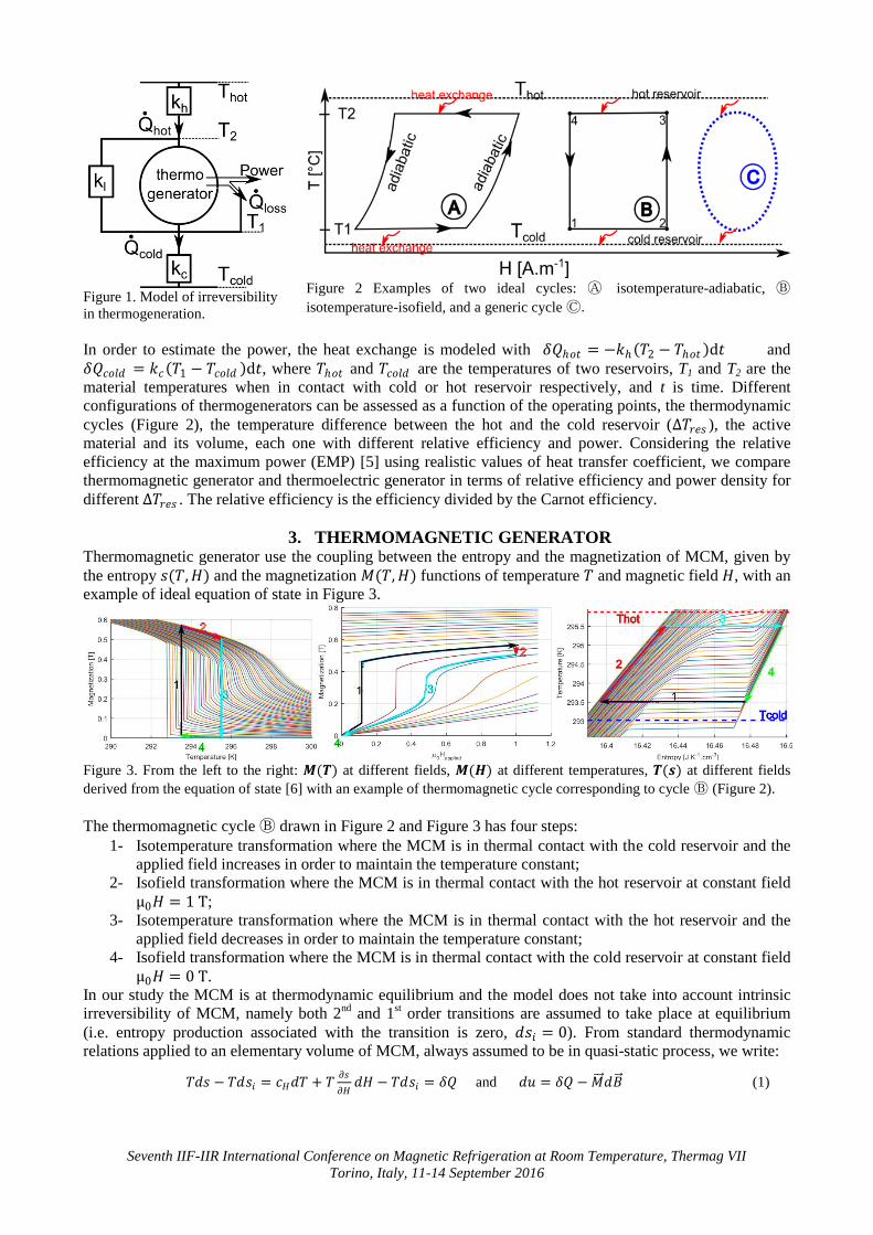
Figure 1. Model of irreversibility
in thermogeneration.
Figure 2 Examples of two ideal cycles: Ⓐ isotemperature-adiabatic, Ⓑ
isotemperature-isofield, and a generic cycle Ⓒ.
In order to estimate the power, the heat exchange is modeled with 𝛿𝑄ℎ𝑜𝑡 = −𝑘ℎ 𝑇2 − 𝑇ℎ𝑜𝑡 d𝑡 and
𝛿𝑄𝑐𝑜𝑙𝑑 = 𝑘𝑐 𝑇1 − 𝑇𝑐𝑜𝑙𝑑 d𝑡, where 𝑇ℎ𝑜𝑡 and 𝑇𝑐𝑜𝑙𝑑 are the temperatures of two reservoirs, T1 and T2 are the
material temperatures when in contact with cold or hot reservoir respectively, and t is time. Different
configurations of thermogenerators can be assessed as a function of the operating points, the thermodynamic
cycles (Figure 2), the temperature difference between the hot and the cold reservoir (Δ𝑇𝑟𝑒𝑠 ), the active
material and its volume, each one with different relative efficiency and power. Considering the relative
efficiency at the maximum power (EMP) [5] using realistic values of heat transfer coefficient, we compare
thermomagnetic generator and thermoelectric generator in terms of relative efficiency and power density for
different Δ𝑇𝑟𝑒𝑠 . The relative efficiency is the efficiency divided by the Carnot efficiency.
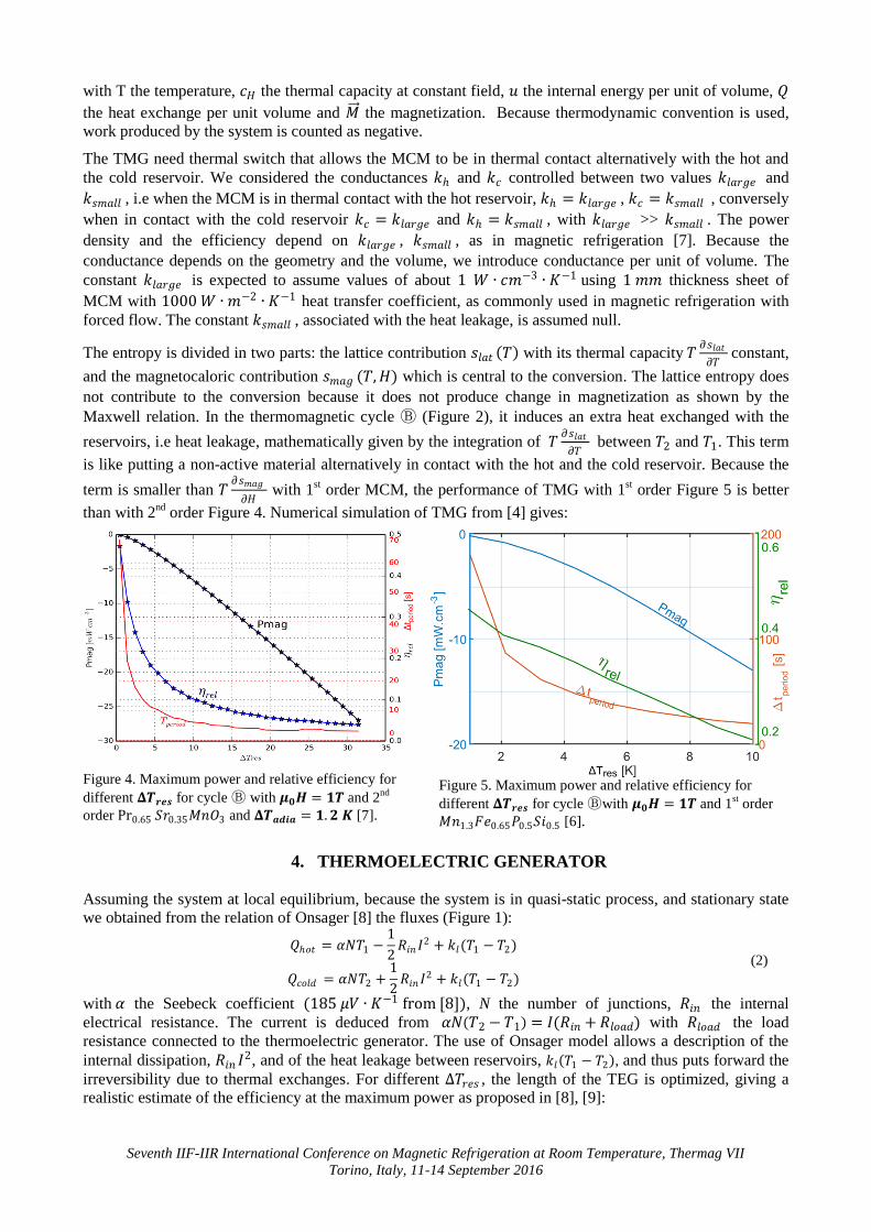
3. THERMOMAGNETIC GENERATOR Thermomagnetic generator use the coupling between the entropy and the magnetization of MCM, given by
the entropy 𝑠(𝑇,𝐻) and the magnetization 𝑀(𝑇,𝐻) functions of temperature 𝑇 and magnetic field 𝐻, with an
example of ideal equation of state in Figure 3.
Figure 3. From the left to the right: 𝑴(𝑻) at different fields, 𝑴(𝑯) at different temperatures, 𝑻(𝒔) at different fields
derived from the equation of state [6] with an example of thermomagnetic cycle corresponding to cycle Ⓑ (Figure 2).
The thermomagnetic cycle Ⓑ drawn in Figure 2 and Figure 3 has four steps:
1- Isotemperature transformation where the MCM is in thermal contact with the cold reservoir and the
applied field increases in order to maintain the temperature constant;
2- Isofield transformation where the MCM is in thermal contact with the hot reservoir at constant field
μ0𝐻 = 1 T;
3- Isotemperature transformation where the MCM is in thermal contact with the hot reservoir and the
applied field decreases in order to maintain the temperature constant;
4- Isofield transformation where the MCM is in thermal contact with the cold reservoir at constant field
μ0𝐻 = 0 T.
In our study the MCM is at thermodynamic equilibrium and the model does not take into account intrinsic
irreversibility of MCM, namely both 2nd
and 1st order transitions are assumed to take place at equilibrium
(i.e. entropy production associated with the transition is zero, 𝑑𝑠𝑖 = 0). From standard thermodynamic
relations applied to an elementary volume of MCM, always assumed to be in quasi-static process, we write:
𝑇𝑑𝑠 − 𝑇𝑑𝑠𝑖 = 𝑐𝐻𝑑𝑇 + 𝑇𝜕𝑠
𝜕𝐻𝑑𝐻 − 𝑇𝑑𝑠𝑖 = 𝛿𝑄 and 𝑑𝑢 = 𝛿𝑄 −𝑀 𝑑𝐵 (1)
Page 4
Seventh IIF-IIR International Conference on Magnetic Refrigeration at Room Temperature, Thermag VII
Torino, Italy, 11-14 September 2016
with T the temperature, 𝑐𝐻 the thermal capacity at constant field, 𝑢 the internal energy per unit of volume, 𝑄
the heat exchange per unit volume and 𝑀 the magnetization. Because thermodynamic convention is used,
work produced by the system is counted as negative.
The TMG need thermal switch that allows the MCM to be in thermal contact alternatively with the hot and
the cold reservoir. We considered the conductances 𝑘ℎ and 𝑘𝑐 controlled between two values 𝑘𝑙𝑎𝑟𝑔𝑒 and
𝑘𝑠𝑚𝑎𝑙𝑙 , i.e when the MCM is in thermal contact with the hot reservoir, 𝑘ℎ = 𝑘𝑙𝑎𝑟𝑔𝑒 , 𝑘𝑐 = 𝑘𝑠𝑚𝑎𝑙𝑙 , conversely
when in contact with the cold reservoir 𝑘𝑐 = 𝑘𝑙𝑎𝑟𝑔𝑒 and 𝑘ℎ = 𝑘𝑠𝑚𝑎𝑙𝑙 , with 𝑘𝑙𝑎𝑟𝑔𝑒 >> 𝑘𝑠𝑚𝑎𝑙𝑙 . The power
density and the efficiency depend on 𝑘𝑙𝑎𝑟𝑔𝑒 , 𝑘𝑠𝑚𝑎𝑙𝑙 , as in magnetic refrigeration [7]. Because the
conductance depends on the geometry and the volume, we introduce conductance per unit of volume. The
constant 𝑘𝑙𝑎𝑟𝑔𝑒 is expected to assume values of about 1 𝑊 ∙ 𝑐𝑚−3 ∙ 𝐾−1 using 1 𝑚𝑚 thickness sheet of
MCM with 1000 𝑊 ∙ 𝑚−2 ∙ 𝐾−1 heat transfer coefficient, as commonly used in magnetic refrigeration with
forced flow. The constant 𝑘𝑠𝑚𝑎𝑙𝑙 , associated with the heat leakage, is assumed null.
The entropy is divided in two parts: the lattice contribution 𝑠𝑙𝑎𝑡 𝑇 with its thermal capacity 𝑇𝜕𝑠𝑙𝑎𝑡
𝜕𝑇 constant,
and the magnetocaloric contribution 𝑠𝑚𝑎𝑔 (𝑇,𝐻) which is central to the conversion. The lattice entropy does
not contribute to the conversion because it does not produce change in magnetization as shown by the
Maxwell relation. In the thermomagnetic cycle Ⓑ (Figure 2), it induces an extra heat exchanged with the
reservoirs, i.e heat leakage, mathematically given by the integration of 𝑇𝜕𝑠𝑙𝑎𝑡
𝜕𝑇 between 𝑇2 and 𝑇1. This term
is like putting a non-active material alternatively in contact with the hot and the cold reservoir. Because the
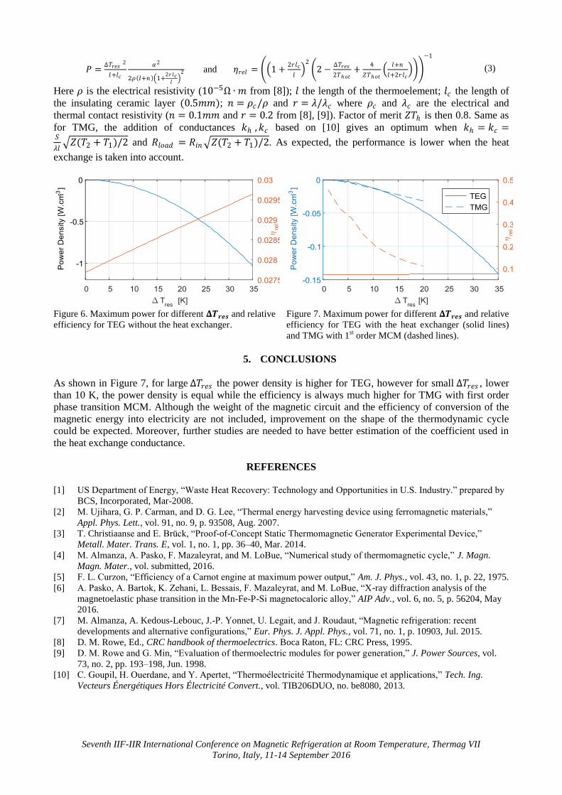
term is smaller than 𝑇𝜕𝑠𝑚𝑎𝑔
𝜕𝐻 with 1
st order MCM, the performance of TMG with 1
st order Figure 5 is better
than with 2nd
order Figure 4. Numerical simulation of TMG from [4] gives:
Figure 4. Maximum power and relative efficiency for
different 𝚫𝑻𝒓𝒆𝒔 for cycle Ⓑ with 𝝁𝟎𝑯 = 𝟏𝑻 and 2nd
order Pr0.65 𝑆𝑟0.35𝑀𝑛𝑂3 and 𝚫𝑻𝒂𝒅𝒊𝒂 = 𝟏.𝟐 𝑲 [7].
Figure 5. Maximum power and relative efficiency for
different 𝚫𝑻𝒓𝒆𝒔 for cycle Ⓑwith 𝝁𝟎𝑯 = 𝟏𝑻 and 1st order
𝑀𝑛1.3𝐹𝑒0.65𝑃0.5𝑆𝑖0.5 [6].
4. THERMOELECTRIC GENERATOR
Assuming the system at local equilibrium, because the system is in quasi-static process, and stationary state
we obtained from the relation of Onsager [8] the fluxes (Figure 1):
𝑄ℎ𝑜𝑡 = 𝛼𝑁𝑇1 −1
2𝑅𝑖𝑛 𝐼
2 + 𝑘𝑙(𝑇1 − 𝑇2)
𝑄𝑐𝑜𝑙𝑑 = 𝛼𝑁𝑇2 +1
2𝑅𝑖𝑛 𝐼
2 + 𝑘𝑙(𝑇1 − 𝑇2)
(2)
with 𝛼 the Seebeck coefficient (185 𝜇𝑉 ∙ 𝐾−1 from [8]), N the number of junctions, 𝑅𝑖𝑛 the internal
electrical resistance. The current is deduced from 𝛼𝑁 𝑇2 −𝑇1 = 𝐼(𝑅𝑖𝑛 + 𝑅𝑙𝑜𝑎𝑑) with 𝑅𝑙𝑜𝑎𝑑 the load
resistance connected to the thermoelectric generator. The use of Onsager model allows a description of the
internal dissipation, 𝑅𝑖𝑛 𝐼2, and of the heat leakage between reservoirs, 𝑘𝑙 𝑇1 − 𝑇2 , and thus puts forward the
irreversibility due to thermal exchanges. For different Δ𝑇𝑟𝑒𝑠 , the length of the TEG is optimized, giving a
realistic estimate of the efficiency at the maximum power as proposed in [8], [9]:
Page 5
Seventh IIF-IIR International Conference on Magnetic Refrigeration at Room Temperature, Thermag VII
Torino, Italy, 11-14 September 2016
𝑃 =Δ𝑇𝑟𝑒𝑠 2
𝑙+𝑙𝑐
𝛼2
2𝜌 𝑙+𝑛 1+2𝑟𝑙𝑐𝑙
2 and 𝜂𝑟𝑒𝑙 = 1 +2𝑟𝑙𝑐
𝑙
2
2 −Δ𝑇𝑟𝑒𝑠
2𝑇ℎ𝑜𝑡+
4
𝑍𝑇ℎ𝑜𝑡
𝑙+𝑛
𝑙+2𝑟𝑙𝑐
−1
(3)
Here 𝜌 is the electrical resistivity (10−5Ω ∙ 𝑚 from [8]); 𝑙 the length of the thermoelement; 𝑙𝑐 the length of
the insulating ceramic layer (0.5𝑚𝑚); 𝑛 = 𝜌𝑐/𝜌 and 𝑟 = 𝜆/𝜆𝑐 where 𝜌𝑐 and 𝜆𝑐 are the electrical and
thermal contact resistivity (𝑛 = 0.1𝑚𝑚 and 𝑟 = 0.2 from [8], [9]). Factor of merit 𝑍𝑇ℎ is then 0.8. Same as
for TMG, the addition of conductances 𝑘ℎ ,𝑘𝑐 based on [10] gives an optimum when 𝑘ℎ = 𝑘𝑐 =𝑆
𝜆𝑙 𝑍(𝑇2 + 𝑇1)/2 and 𝑅𝑙𝑜𝑎𝑑 = 𝑅𝑖𝑛 𝑍(𝑇2 + 𝑇1)/2. As expected, the performance is lower when the heat
exchange is taken into account.
Figure 6. Maximum power for different 𝚫𝑻𝒓𝒆𝒔 and relative
efficiency for TEG without the heat exchanger.
Figure 7. Maximum power for different 𝚫𝑻𝒓𝒆𝒔 and relative
efficiency for TEG with the heat exchanger (solid lines)
and TMG with 1st order MCM (dashed lines).
5. CONCLUSIONS
As shown in Figure 7, for large Δ𝑇𝑟𝑒𝑠 the power density is higher for TEG, however for small Δ𝑇𝑟𝑒𝑠 , lower
than 10 K, the power density is equal while the efficiency is always much higher for TMG with first order
phase transition MCM. Although the weight of the magnetic circuit and the efficiency of conversion of the
magnetic energy into electricity are not included, improvement on the shape of the thermodynamic cycle
could be expected. Moreover, further studies are needed to have better estimation of the coefficient used in
the heat exchange conductance.
REFERENCES
[1] US Department of Energy, “Waste Heat Recovery: Technology and Opportunities in U.S. Industry.” prepared by
BCS, Incorporated, Mar-2008.
[2] M. Ujihara, G. P. Carman, and D. G. Lee, “Thermal energy harvesting device using ferromagnetic materials,”
Appl. Phys. Lett., vol. 91, no. 9, p. 93508, Aug. 2007.
[3] T. Christiaanse and E. Brück, “Proof-of-Concept Static Thermomagnetic Generator Experimental Device,”
Metall. Mater. Trans. E, vol. 1, no. 1, pp. 36–40, Mar. 2014.
[4] M. Almanza, A. Pasko, F. Mazaleyrat, and M. LoBue, “Numerical study of thermomagnetic cycle,” J. Magn.
Magn. Mater., vol. submitted, 2016.
[5] F. L. Curzon, “Efficiency of a Carnot engine at maximum power output,” Am. J. Phys., vol. 43, no. 1, p. 22, 1975.
[6] A. Pasko, A. Bartok, K. Zehani, L. Bessais, F. Mazaleyrat, and M. LoBue, “X-ray diffraction analysis of the
magnetoelastic phase transition in the Mn-Fe-P-Si magnetocaloric alloy,” AIP Adv., vol. 6, no. 5, p. 56204, May
2016.
[7] M. Almanza, A. Kedous-Lebouc, J.-P. Yonnet, U. Legait, and J. Roudaut, “Magnetic refrigeration: recent
developments and alternative configurations,” Eur. Phys. J. Appl. Phys., vol. 71, no. 1, p. 10903, Jul. 2015.
[8] D. M. Rowe, Ed., CRC handbook of thermoelectrics. Boca Raton, FL: CRC Press, 1995.
[9] D. M. Rowe and G. Min, “Evaluation of thermoelectric modules for power generation,” J. Power Sources, vol.
73, no. 2, pp. 193–198, Jun. 1998.
[10] C. Goupil, H. Ouerdane, and Y. Apertet, “Thermoélectricité Thermodynamique et applications,” Tech. Ing.
Vecteurs Énergétiques Hors Électricité Convert., vol. TIB206DUO, no. be8080, 2013.