122
Thermo PAL for the PAL Autosampler User Guide XCALI-97169 Revision D March 2011

Thermo PALfor the PAL Autosampler
User Guide
XCALI-97169 Revision D March 2011
© 2011 Thermo Fisher Scientific Inc. All rights reserved.
The following are registered trademarks in the United States and possibly other countries: Agilent and ChemStation are registered trademarks of Agilent Technologies Inc. Analyst is a registered trademark of AB Sciex Pte. Ltd. Cheminert is a registered trademark of Valco Instruments Company, Inc. Kalrez is a registered trademark of E.I. du Pont de Nemours & Company. PAL is a trademark of CTC Analytics AG. Ryton is a registered trademark of Chevron Phillips Chemical Company. Simriz is a registered trademark of Carl Freudenberg KG Corporation. Windows is a registered trademark of Microsoft Corporation.
Empower and MassLynx are trademarks of Waters Corporation. PEEK is a trademark of Victrex plc.
All other trademarks are the property of Thermo Fisher Scientific and its subsidiaries.
Thermo Fisher Scientific Inc. provides this document to its customers with a product purchase to use in the product operation. This document is copyright protected and any reproduction of the whole or any part of this document is strictly prohibited, except with the written authorization of Thermo Fisher Scientific Inc.
The contents of this document are subject to change without notice. All technical information in this document is for reference purposes only. System configurations and specifications in this document supersede all previous information received by the purchaser.
Thermo Fisher Scientific Inc. makes no representations that this document is complete, accurate or error-free and assumes no responsibility and will not be liable for any errors, omissions, damage or loss that might result from any use of this document, even if the information in the document is followed properly.
This document is not part of any sales contract between Thermo Fisher Scientific Inc. and a purchaser. This document shall in no way govern or modify any Terms and Conditions of Sale, which Terms and Conditions of Sale shall govern all conflicting information between the two documents.
Release history: Revision A, December 2005; Revision B, February 2009; Revision C, April 2010; Revision D, March 2011.
Software version: Xcalibur 2.1 or later, Thermo PAL 1.0Firmware version: 2.5.0 for the PAL autosampler
For Research Use Only. Not for use in diagnostic procedures.
Regulatory Compliance
Thermo Fisher Scientific performs complete testing and evaluation of its products to ensure full compliance with applicable domestic and international regulations. When the system is delivered to you, it meets all pertinent electromagnetic compatibility (EMC) and safety standards as described in CTC Analytics PAL System User Manual.
Changes that you make to your system may void compliance with one or more of these EMC and safety standards. Changes to your system include replacing a part or adding components, options, or peripherals not specifically authorized and qualified by Thermo Fisher Scientific. To ensure continued compliance with EMC and safety standards, replacement parts and additional components, options, and peripherals must be ordered from Thermo Fisher Scientific or one of its authorized representatives.
FCC Compliance Statement
Notice on Lifting and Handling ofThermo Scientific Instruments
For your safety, and in compliance with international regulations, the physical handling of this Thermo Fisher Scientific instrument requires a team effort to lift and/or move the instrument. This instrument is too heavy and/or bulky for one person alone to handle safely.
Notice on the Proper Use ofThermo Scientific Instruments
In compliance with international regulations: Use of this instrument in a manner not specified by Thermo Fisher Scientific could impair any protection provided by the instrument.
THIS DEVICE COMPLIES WITH PART 15 OF THE FCC RULES. OPERATION IS SUBJECT TO THE FOLLOWING TWO CONDITIONS: (1) THIS DEVICE MAY NOT CAUSE HARMFUL INTERFERENCE, AND (2) THIS DEVICE MUST ACCEPT ANY INTERFERENCE RECEIVED, INCLUDING INTERFERENCE THAT MAY CAUSE UNDESIRED OPERATION.
CAUTION Read and understand the various precautionary notes, signs, and symbols contained inside this manual pertaining to the safe use and operation of this product before using the device.

Notice on the Susceptibility to Electromagnetic Transmissions
Your instrument is designed to work in a controlled electromagnetic environment. Do not use radio frequency transmitters, such as mobile phones, in close proximity to the instrument.
For manufacturing location, see the label on the instrument.
WEEE Compliance
This product is required to comply with the European Union’s Waste Electrical & Electronic Equipment (WEEE) Directive 2002/96/EC. It is marked with the following symbol:
Thermo Fisher Scientific has contracted with one or more recycling or disposal companies in each European Union (EU) Member State, and these companies should dispose of or recycle this product. See www.thermo.com/WEEERoHS for further information on Thermo Fisher Scientific’s compliance with these Directives and the recyclers in your country.
WEEE Konformität
Dieses Produkt muss die EU Waste Electrical & Electronic Equipment (WEEE) Richtlinie 2002/96/EC erfüllen. Das Produkt ist durch folgendes Symbol gekennzeichnet:
Thermo Fisher Scientific hat Vereinbarungen mit Verwertungs-/Entsorgungsfirmen in allen EU-Mitgliedsstaaten getroffen, damit dieses Produkt durch diese Firmen wiederverwertet oder entsorgt werden kann. Mehr Information über die Einhaltung dieser Anweisungen durch Thermo Fisher Scientific, über die Verwerter, und weitere Hinweise, die nützlich sind, um die Produkte zu identifizieren, die unter diese RoHS Anweisung fallen, finden sie unter www.thermo.com/WEEERoHS.
Conformité DEEE
Ce produit doit être conforme à la directive européenne (2002/96/EC) des Déchets d'Equipements Electriques et Electroniques (DEEE). Il est marqué par le symbole suivant:
Thermo Fisher Scientific s'est associé avec une ou plusieurs compagnies de recyclage dans chaque état membre de l’union européenne et ce produit devrait être collecté ou recyclé par celles-ci. Davantage d'informations sur la conformité de Thermo Fisher Scientific à ces directives, les recycleurs dans votre pays et les informations sur les produits Thermo Fisher Scientific qui peuvent aider la détection des substances sujettes à la directive RoHS sont disponibles sur www.thermo.com/WEEERoHS.
C
Contents
Preface . . . . . . . . . . . . . . . . . . . . . . . . . . . . . . . . . . . . . . . . . . . . . . . . . . . . . . . . . . . . . . ixRelated Documentation . . . . . . . . . . . . . . . . . . . . . . . . . . . . . . . . . . . . . . . . . . .ixSafety and Special Notices . . . . . . . . . . . . . . . . . . . . . . . . . . . . . . . . . . . . . . . . . xContacting Us . . . . . . . . . . . . . . . . . . . . . . . . . . . . . . . . . . . . . . . . . . . . . . . . . . x
Chapter 1 Getting Connected. . . . . . . . . . . . . . . . . . . . . . . . . . . . . . . . . . . . . . . . . . . . . . . . . . . . . .1Ordering Information . . . . . . . . . . . . . . . . . . . . . . . . . . . . . . . . . . . . . . . . . . . . . 1Setting Up an LC/MS System with the Autosampler. . . . . . . . . . . . . . . . . . . . . . 2Connecting the Contact Closure Cables . . . . . . . . . . . . . . . . . . . . . . . . . . . . . . . 3
Making Contact Closure with Thermo Scientific Devices . . . . . . . . . . . . . . . . 4Connecting the Start Pump to the Sample Pump in a Dual Pump
System . . . . . . . . . . . . . . . . . . . . . . . . . . . . . . . . . . . . . . . . . . . . . . . . . . . . . 8Making Contact Closure with the Autosampler, an Agilent Pump, and
an MS Detector . . . . . . . . . . . . . . . . . . . . . . . . . . . . . . . . . . . . . . . . . . . . . 10Connecting the PAL to the Data System Computer . . . . . . . . . . . . . . . . . . . . . 14
Chapter 2 Getting Started. . . . . . . . . . . . . . . . . . . . . . . . . . . . . . . . . . . . . . . . . . . . . . . . . . . . . . . .15Adding the Autosampler to the Xcalibur Instrument Configuration . . . . . . . . . 15Firmware Versions Supported . . . . . . . . . . . . . . . . . . . . . . . . . . . . . . . . . . . . . . 20Using the Autosampler Control Terminal . . . . . . . . . . . . . . . . . . . . . . . . . . . . . 20
Selecting the Tray Type. . . . . . . . . . . . . . . . . . . . . . . . . . . . . . . . . . . . . . . . . 21Changing the Pulse Time Setting . . . . . . . . . . . . . . . . . . . . . . . . . . . . . . . . . 22
Specifying the Instrument Method Parameters for the Autosampler . . . . . . . . . 24Viewing the Method Summary . . . . . . . . . . . . . . . . . . . . . . . . . . . . . . . . . . . . . 31
Chapter 3 Creating Custom Templates and Macros . . . . . . . . . . . . . . . . . . . . . . . . . . . . . . . . .33Using the Template Editor to Create Custom Templates . . . . . . . . . . . . . . . . . 33Testing a Custom Template . . . . . . . . . . . . . . . . . . . . . . . . . . . . . . . . . . . . . . . 37Viewing the Template Summary . . . . . . . . . . . . . . . . . . . . . . . . . . . . . . . . . . . . 40Standard Macros . . . . . . . . . . . . . . . . . . . . . . . . . . . . . . . . . . . . . . . . . . . . . . . . 42Using the Macro Editor to Create Custom Macros . . . . . . . . . . . . . . . . . . . . . . 43Defining Variables. . . . . . . . . . . . . . . . . . . . . . . . . . . . . . . . . . . . . . . . . . . . . . . 48
Thermo Scientific Thermo PAL User Guide vii
Contents
Chapter 4 Using the Direct Controls to Operate the Autosampler . . . . . . . . . . . . . . . . . . . . .51Opening the Direct Control Dialog Box . . . . . . . . . . . . . . . . . . . . . . . . . . . . . . 51Making Single Injections from the Tune Window. . . . . . . . . . . . . . . . . . . . . . . 53Changing the Tray Configuration . . . . . . . . . . . . . . . . . . . . . . . . . . . . . . . . . . . 56Specifying the Location of the Direct Control Methods . . . . . . . . . . . . . . . . . . 57Wrapping Direct Control Injections with Additional Macros . . . . . . . . . . . . . . 60
Chapter 5 Using Dynamic Load and Wash (DLW) . . . . . . . . . . . . . . . . . . . . . . . . . . . . . . . . . . .61Overview . . . . . . . . . . . . . . . . . . . . . . . . . . . . . . . . . . . . . . . . . . . . . . . . . . . . . . 61Installing Cycle Composer Macros or ICC Cycles . . . . . . . . . . . . . . . . . . . . . . . 62
General Considerations . . . . . . . . . . . . . . . . . . . . . . . . . . . . . . . . . . . . . . . . . 64Priming the Solvent Lines, Wash1 and Wash2 . . . . . . . . . . . . . . . . . . . . . . . 64Standard DLW Injection Cycle . . . . . . . . . . . . . . . . . . . . . . . . . . . . . . . . . . . 66Fast DLW Injection Cycle. . . . . . . . . . . . . . . . . . . . . . . . . . . . . . . . . . . . . . . 68
Operating Dynamic Load and Wash (DLW) . . . . . . . . . . . . . . . . . . . . . . . . . . 70Priming the Solvent Lines . . . . . . . . . . . . . . . . . . . . . . . . . . . . . . . . . . . . . . . 70Location of Solvent and Waste Bottles. . . . . . . . . . . . . . . . . . . . . . . . . . . . . . 71DLW Pumps . . . . . . . . . . . . . . . . . . . . . . . . . . . . . . . . . . . . . . . . . . . . . . . . . 71DLW Actuator/Solenoid . . . . . . . . . . . . . . . . . . . . . . . . . . . . . . . . . . . . . . . . 71
DLW Cycle Step-by-Step . . . . . . . . . . . . . . . . . . . . . . . . . . . . . . . . . . . . . . . . . 73Cycle for Standard Injection . . . . . . . . . . . . . . . . . . . . . . . . . . . . . . . . . . . . . 73Additional Valve Toggle Step to DLW Standard Cycle . . . . . . . . . . . . . . . . . 86Cycle for Fast Injection . . . . . . . . . . . . . . . . . . . . . . . . . . . . . . . . . . . . . . . . . 95
Index . . . . . . . . . . . . . . . . . . . . . . . . . . . . . . . . . . . . . . . . . . . . . . . . . . . . . . . . . . . . . . .107
viii Thermo PAL User Guide Thermo Scientific

P
Preface
The CTC PAL™ autosampler manufactured by CTC Analytics is supplied by Thermo Fisher Scientific as part of a solution for high-throughput LC/MS applications. Thermo PAL, one of the device drivers provided on the LC Devices software CD, is the device driver that enables the Xcalibur™ data system to control the autosampler.
This user guide provides you with information on how to connect the Thermo PAL autosampler to other devices in the LC/MS system and how to operate it from the Xcalibur data system. This manual is provided as a PDF file only. To access this manual, choose the following from the computer desktop:
Start > All Programs > Thermo Instruments > Manuals > LC Devices > CTC > Thermo PAL
To provide comments about this document, click the link below. Thank you in advance for your help.
Related DocumentationIn addition to this manual, the Thermo PAL autosampler includes Help.
Thermo Scientific Thermo PAL User Guide ix

Preface
Safety and Special NoticesMake sure you follow the precautionary statements presented in this guide. The safety and other special notices appear in boxes.
Safety and special notices include the following:
Contacting UsThere are several ways to contact Thermo Fisher Scientific for the information you need.
To contact Technical Support
Find software updates and utilities to download at mssupport.thermo.com.
To contact Customer Service for ordering information
To get local contact information for sales or service
Go to www.thermoscientific.com/wps/portal/ts/contactus.
CAUTION Highlights hazards to humans, property, or the environment. Each CAUTION notice is accompanied by an appropriate CAUTION symbol.
IMPORTANT Highlights information necessary to prevent damage to software, loss of data, or invalid test results; or might contain information that is critical for optimal performance of the system.
Note Highlights information of general interest.
Tip Highlights helpful information that can make a task easier.
Phone 800-532-4752
Fax 561-688-8736
E-mail [email protected]
Knowledge base www.thermokb.com
Phone 800-532-4752
Fax 561-688-8731
E-mail [email protected]
Web site www.thermo.com/ms
x Thermo PAL User Guide Thermo Scientific

Preface
To copy manuals from the Internet
Go to mssupport.thermo.com, agree to the Terms and Conditions, and then click Customer Manuals in the left margin of the window.
To suggest changes to documentation or to Help
• Fill out a reader survey online at www.surveymonkey.com/s/PQM6P62.
• Send an e-mail message to the Technical Publications Editor at [email protected].
Thermo Scientific Thermo PAL User Guide xi

1
Getting Connected
The Thermo PAL is a high-throughput autosampler manufactured by CTC Analytics and supplied by Thermo Fisher Scientific. For high-throughput LC/MS applications, use the PAL, a Thermo Scientific or an Agilent™ liquid chromatography (LC) pump, and a Thermo Scientific mass spectrometer (MS) detector.
This chapter describes the contact closure connections between the PAL, one or two Thermo Scientific LC pumps or an Agilent pump, a Thermo Scientific MS detector, and the Xcalibur data system computer. For information on setting up the PAL, refer to the CTC Analytics PAL System User Manual.
Ordering InformationThe Thermo PAL options that Thermo Fisher Scientific supplies include the serial communication cable that you use to connect the Thermo PAL to the data system computer and the contact closure cable that you use to connect the Thermo PAL to a Thermo Scientific LC pump and a Thermo Scientific MS detector.
CAUTION Follow all of the recommendations given in the Safety Information section of the CTC Analytics PAL System User Manual. The Safety Information section includes information on the PAL electrical hazards, lithium battery, and safety labels.
Contents
• Ordering Information
• System Synchronization Connections
• System Synchronization Connections
• Connecting the Accela Open Autosampler to the Data System Computer
Thermo Scientific Thermo PAL User Guide 1

1 Getting ConnectedSetting Up an LC/MS System with the Autosampler
Table 1 lists the Thermo PAL options that you can order from Thermo Fisher Scientific.
Table 2 lists the contact closure cables used to connect an Agilent pump to a Thermo Scientific MS detector and an autosampler. You can order the DB15 × 15 wire cable from Agilent or Thermo Fisher Scientific.
Setting Up an LC/MS System with the AutosamplerTypical stackable setups include placing the autosampler on top of the two pumps in a dual-pump setup, and to the left of the MS detector. Ensure that the stackable area for the autosampler is level, and that system cables behind the autosampler have adequate space.
For information on assembling the PAL and connecting the solvent lines, refer to the CTC Analytics PAL System User Manual supplied in hard copy format with the autosampler. During the installation of a Thermo Scientific MS detector, a Thermo Fisher Scientific field service engineer connects the LC system to the MS detector.
Table 1. Thermo PAL ordering information
Part number Description
OPTON 13008 HTS PAL
OPTON 13009 HTC PAL
OPTON 13010 HTC PAL with the 98 × 2 mL tray holder
Table 2. Contact closure cables used to connect an Agilent pump
Part number Supplier Description
CBL 7890 CTC Analytics PAL Interface Cable for APG RemoteDB15 connector × DB9 connector cable
00012-27716 Thermo Fisher Scientific DB15 connector × 15 wire cable
G1103-61611 Agilent DB15 connector × 15 wire cable
CAUTION To prevent damage to the injection unit during operation, place the autosampler on a level surface.
2 Thermo PAL User Guide Thermo Scientific

1 Getting ConnectedSetting Up an LC/MS System with the Autosampler
Figure 1 shows a front view of the Thermo PAL autosampler. During installation, a Thermo Fisher Scientific field service engineer connects the solvent lines between the injection valve and the LC pump and between the injection valve and the Thermo Scientific mass spectrometer.
Figure 1. PAL autosampler
Courtesy of CTC Analytics
Control terminal
Syringe
Injection unit
Thermo Scientific Thermo PAL User Guide 3
1 Getting Connected(see Figure 3) (seeFigure 3) (see Figure 3) (see Figure 3) (see Figure 4) (see Figure 5) (see Figure 2 on page 5) (see Figure 8) (see Figure 9) (see Figure 10 on
(see Figure 3) (seeFigure 3) (see Figure 3) (see Figure 3) (see Figure 4) (see Figure 5) (see Figure 2 on page 5) (see
Figure 8) (see Figure 9) (see Figure 10 on page 13)Connecting the Contact Closure CablesDuring an injection cycle, the PAL sends and receives electrical signals. To start an injection cycle, the autosampler must receive an electrical signal from the LC pump. When the autosampler completes an injection cycle, it sends an electrical signal to the LC pump. For more information on interfacing the PAL with other devices, refer to the CTC Analytics PAL System User Manual (Interfacing the PAL to Other Devices section).
This section describes how to hardwire one or two LC pumps and a Thermo Scientific MS detector to the PAL for contact closure.
To make the contact closure connections, follow the procedure for your LC/MS system:
• Making Contact Closure with Thermo Scientific Devices
• Connecting the Start Pump to the Sample Pump in a Dual Pump System
• Dual-pump setup with two Accela Pumps
Making Contact Closure with Thermo Scientific Devices
The accessory kit supplied by Thermo Fisher Scientific contains the contact closure cables that you need to connect the PAL to an LC/MS system with one or two Thermo Scientific LC pumps and a Thermo Scientific MS detector.
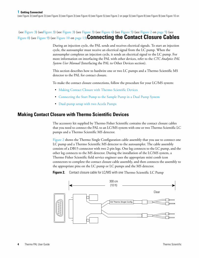
Figure 2 shows the Thermo Single Configuration cable assembly that you use to connect one LC pump and a Thermo Scientific MS detector to the autosampler. The cable assembly consists of a DB15 connector with two 2-pin legs. One leg connects to the LC pump, and the other leg connects to the MS detector. During the installation of the LC/MS system, a Thermo Fisher Scientific field service engineer uses the appropriate mini comb icon connectors to complete the contact closure cable assembly, and then connects the assembly to the appropriate pins on the LC pump or LC pumps and the MS detector.
Figure 2. Contact closure cable for LC/MS with one Thermo Scientific LC Pump
Cbl Thermo Single Config.
300 cm(10 ft)
Clear
4 Thermo PAL User Guide Thermo Scientific
1 Getting Connected(see Figure 3) (seeFigure 3) (see Figure 3) (see Figure 3) (see Figure 4) (see Figure 5) (see Figure 2 on page 5) (see Figure 8) (see Figure 9) (see Figure 10 on
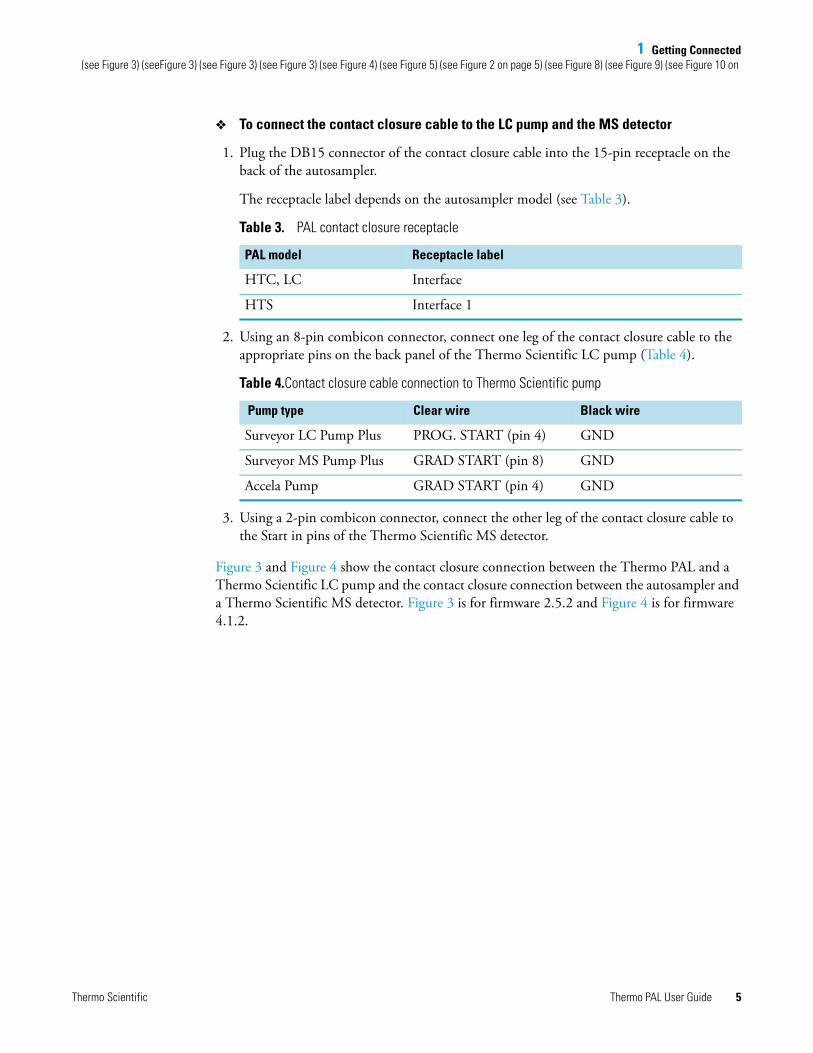
To connect the contact closure cable to the LC pump and the MS detector
1. Plug the DB15 connector of the contact closure cable into the 15-pin receptacle on the back of the autosampler.
The receptacle label depends on the autosampler model (see Table 3).
2. Using an 8-pin combicon connector, connect one leg of the contact closure cable to the appropriate pins on the back panel of the Thermo Scientific LC pump (Table 4).
3. Using a 2-pin combicon connector, connect the other leg of the contact closure cable to the Start in pins of the Thermo Scientific MS detector.
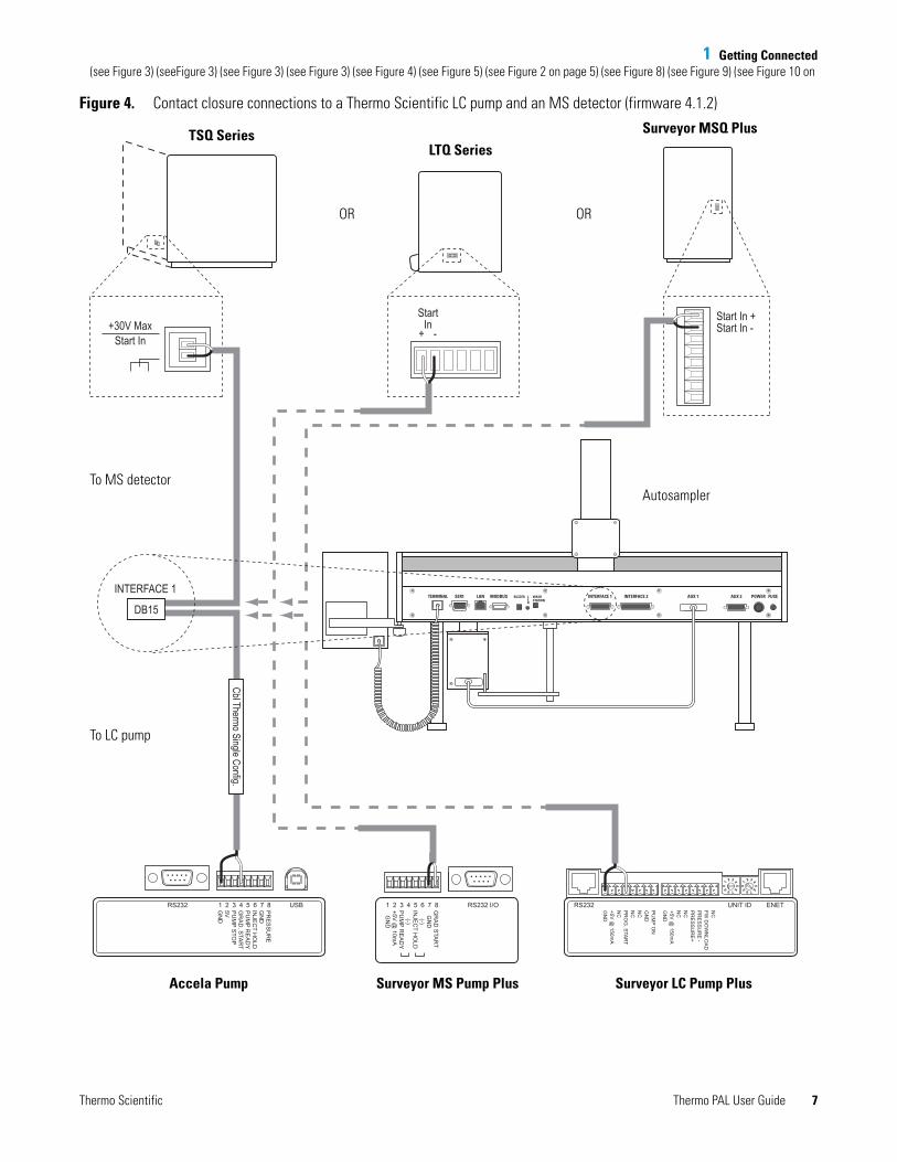
Figure 3 and Figure 4 show the contact closure connection between the Thermo PAL and a Thermo Scientific LC pump and the contact closure connection between the autosampler and a Thermo Scientific MS detector. Figure 3 is for firmware 2.5.2 and Figure 4 is for firmware 4.1.2.
Table 3. PAL contact closure receptacle
PAL model Receptacle label
HTC, LC Interface
HTS Interface 1
Table 4.Contact closure cable connection to Thermo Scientific pump
Pump type Clear wire Black wire
Surveyor LC Pump Plus PROG. START (pin 4) GND
Surveyor MS Pump Plus GRAD START (pin 8) GND
Accela Pump GRAD START (pin 4) GND
Thermo Scientific Thermo PAL User Guide 5

1 Getting Connected(see Figure 3) (seeFigure 3) (see Figure 3) (see Figure 3) (see Figure 4) (see Figure 5) (see Figure 2 on page 5) (see Figure 8) (see Figure 9) (see Figure 10 on
Figure 3. Contact closure connections to a Thermo Scientific LC pump and an MS detector (firmware 2.5.2)
RS232 1 2 3 4 5 6 7 8 USB RS232 I/OPR
ES
SU
RE
GN
DIN
JEC
T HO
LDP
UM
P RE
AD
YG
RA
D. S
TAR
TP
UM
P STO
P5VG
ND
RS232 UNIT ID ENETPU
MP O
NG
ND
NC
NC
PR
OG
. STA
RT
NC
+5V @
150mA
GN
D
NC
FW D
OW
NLO
AD
PR
ES
SU
RE
-P
RE
SS
UR
E+
NC
NC
+5V @
150mA
GN
D
1 2 3 4 5 6 7 8GR
AD
STA
RT
GN
D (-)IN
JEC
T HO
LD (-)P
UM
P RE
AD
Y+5V
@ 10m
A G
ND
POWERINTERFACE SER2SER3 SER1WASHSTATION
BUZZERLEDAUX
StartIn
+ -Start In +Start In -+30V Max
Start In
INTERFACE
Cbl Thermo Single Config. DB15
TSQ SeriesLTQ Series
Surveyor MSQ Plus
OR OR
To MS detector
To LC pump
Accela Pump Surveyor MS Pump Plus Surveyor LC Pump Plus
Autosample
6 Thermo PAL User Guide Thermo Scientific
1 Getting Connected(see Figure 3) (seeFigure 3) (see Figure 3) (see Figure 3) (see Figure 4) (see Figure 5) (see Figure 2 on page 5) (see Figure 8) (see Figure 9) (see Figure 10 on
Figure 4. Contact closure connections to a Thermo Scientific LC pump and an MS detector (firmware 4.1.2)
RS232 1 2 3 4 5 6 7 8 USB RS232 I/OPR
ES
SU
RE
GN
DIN
JEC
T HO
LDP
UM
P RE
AD
YG
RA
D. S
TAR
TP
UM
P STO
P5VG
ND
RS232 UNIT ID ENETPU
MP O
NG
ND
NC
NC
PR
OG
. STA
RT
NC
+5V @
150mA
GN
D
NC
FW D
OW
NLO
AD
PR
ES
SU
RE
-P
RE
SS
UR
E+
NC
NC
+5V @
150mA
GN
D
1 2 3 4 5 6 7 8GR
AD
STA
RT
GN
D (-)IN
JEC
T HO
LD (-)P
UM
P RE
AD
Y+5V
@ 10m
A G
ND
AUX 2 POWER FUSEAUX 1INTERFACE 2INTERFACE 1TERMINAL SER1 LAN MODBUS BUZZER WASHSTATION
LED
StartIn
+ -Start In +Start In -+30V Max
Start In
INTERFACE 1
Cbl Thermo Single Config.
DB15
TSQ SeriesLTQ Series
Surveyor MSQ Plus
OR OR
To MS detector
To LC pump
Accela Pump Surveyor MS Pump Plus Surveyor LC Pump Plus
Autosampler
Thermo Scientific Thermo PAL User Guide 7
1 Getting Connected(see Figure 3) (seeFigure 3) (see Figure 3) (see Figure 3) (see Figure 4) (see Figure 5) (see Figure 2 on page 5) (see Figure 8) (see Figure 9) (see Figure 10 on
Connecting the Start Pump to the Sample Pump in a Dual Pump System
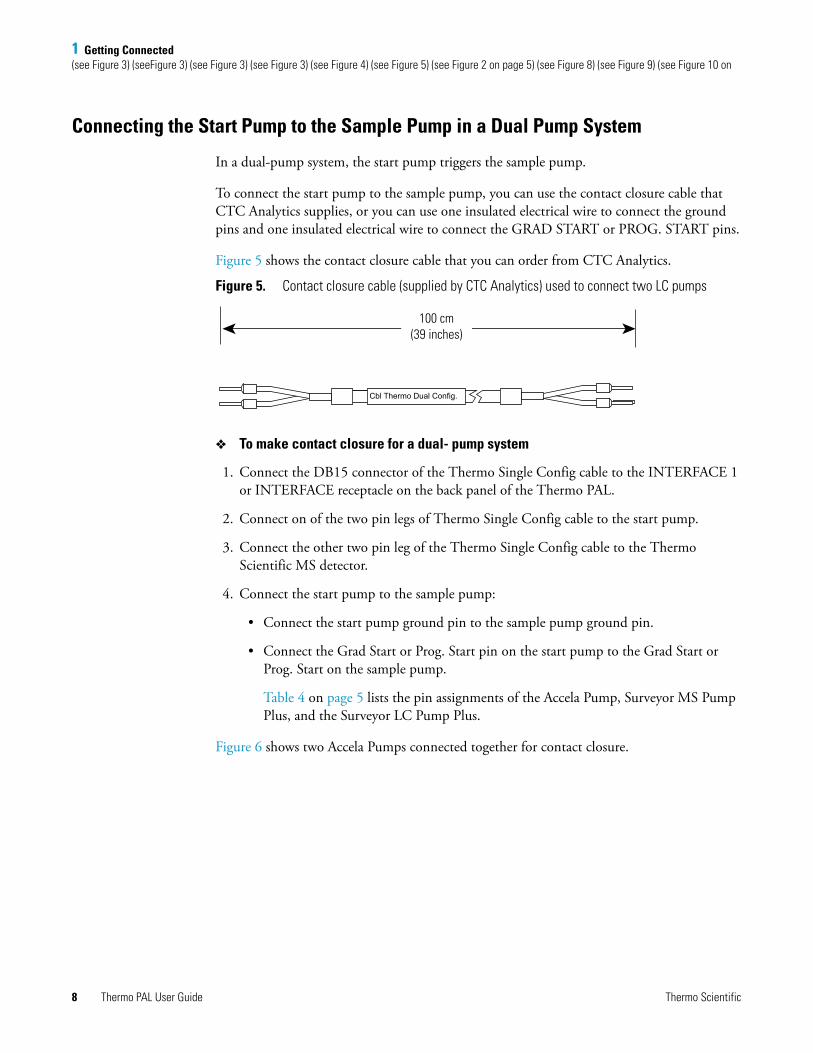
In a dual-pump system, the start pump triggers the sample pump.
To connect the start pump to the sample pump, you can use the contact closure cable that CTC Analytics supplies, or you can use one insulated electrical wire to connect the ground pins and one insulated electrical wire to connect the GRAD START or PROG. START pins.
Figure 5 shows the contact closure cable that you can order from CTC Analytics.
Figure 5. Contact closure cable (supplied by CTC Analytics) used to connect two LC pumps
To make contact closure for a dual- pump system
1. Connect the DB15 connector of the Thermo Single Config cable to the INTERFACE 1 or INTERFACE receptacle on the back panel of the Thermo PAL.
2. Connect on of the two pin legs of Thermo Single Config cable to the start pump.
3. Connect the other two pin leg of the Thermo Single Config cable to the Thermo Scientific MS detector.
4. Connect the start pump to the sample pump:
• Connect the start pump ground pin to the sample pump ground pin.
• Connect the Grad Start or Prog. Start pin on the start pump to the Grad Start or Prog. Start on the sample pump.
Table 4 on page 5 lists the pin assignments of the Accela Pump, Surveyor MS Pump Plus, and the Surveyor LC Pump Plus.
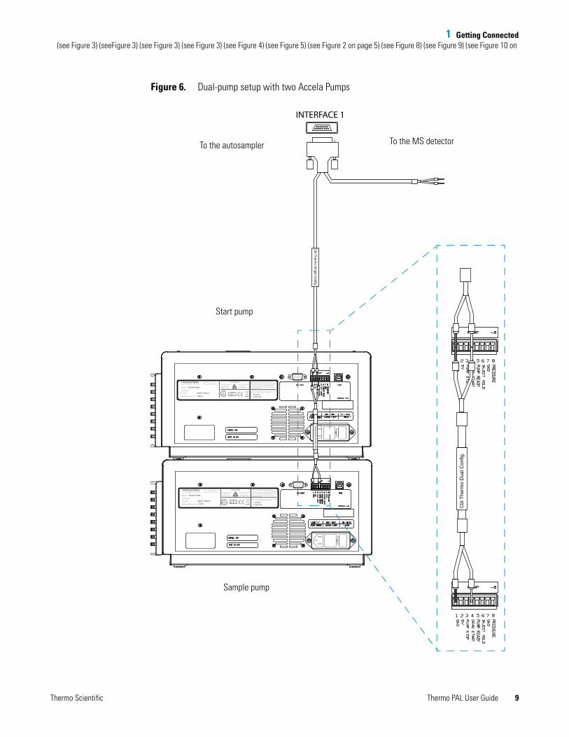
Figure 6 shows two Accela Pumps connected together for contact closure.
Cbl Thermo Dual Config.
100 cm(39 inches)
8 Thermo PAL User Guide Thermo Scientific
1 Getting Connected(see Figure 3) (seeFigure 3) (see Figure 3) (see Figure 3) (see Figure 4) (see Figure 5) (see Figure 2 on page 5) (see Figure 8) (see Figure 9) (see Figure 10 on
Figure 6. Dual-pump setup with two Accela Pumps
Accela Pump
60057-6001012472
5,653,8766,248,157B1
61010 - 1
Model:
Serial No:
Part No:
Options/Firmware:
This product is manufactured under, and covered by,one or more of the following U.S. patents:
355 River Oaks ParkwaySan Jose, CA 95134 U.S.A.
This device complies with FCC Rules, Part 15. Operation is subject to the following two conditions: (1) This device may not cause harmful interference, and (2) This device must accept any interference received, including interference that may cause undesired operation.
DISCONNECT INPUT POWER BEFORE OPENING COVER.
REFER ALL SERVICETO QUALIFIEDPERSONNEL ONLY.
CAUTION
Cbl
The
rmo
Dua
l Con
fig.
Cbl
The
rmo
Dua
l Con
fig.
INTERFACE 1
Cbl Therm
o Single C
onfig.
To the autosampler To the MS detector
Start pump
Sample pump
Thermo Scientific Thermo PAL User Guide 9
1 Getting Connected(see Figure 3) (seeFigure 3) (see Figure 3) (see Figure 3) (see Figure 4) (see Figure 5) (see Figure 2 on page 5) (see Figure 8) (see Figure 9) (see Figure 10 on
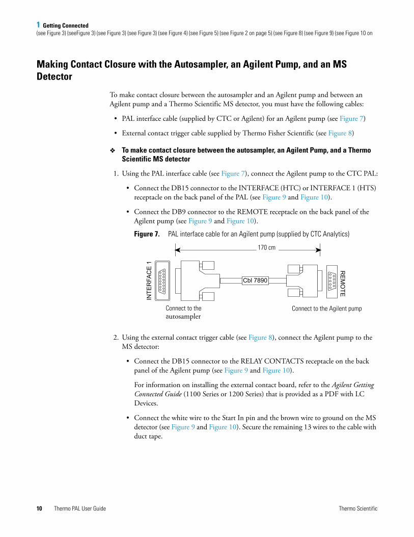
Making Contact Closure with the Autosampler, an Agilent Pump, and an MS Detector
To make contact closure between the autosampler and an Agilent pump and between an Agilent pump and a Thermo Scientific MS detector, you must have the following cables:
• PAL interface cable (supplied by CTC or Agilent) for an Agilent pump (see Figure 7)
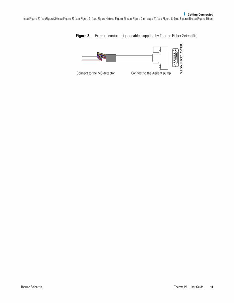
• External contact trigger cable supplied by Thermo Fisher Scientific (see Figure 8)
To make contact closure between the autosampler, an Agilent Pump, and a Thermo Scientific MS detector
1. Using the PAL interface cable (see Figure 7), connect the Agilent pump to the CTC PAL:
• Connect the DB15 connector to the INTERFACE (HTC) or INTERFACE 1 (HTS) receptacle on the back panel of the PAL (see Figure 9 and Figure 10).
• Connect the DB9 connector to the REMOTE receptacle on the back panel of the Agilent pump (see Figure 9 and Figure 10).
Figure 7. PAL interface cable for an Agilent pump (supplied by CTC Analytics)
2. Using the external contact trigger cable (see Figure 8), connect the Agilent pump to the MS detector:
• Connect the DB15 connector to the RELAY CONTACTS receptacle on the back panel of the Agilent pump (see Figure 9 and Figure 10).
For information on installing the external contact board, refer to the Agilent Getting Connected Guide (1100 Series or 1200 Series) that is provided as a PDF with LC Devices.
• Connect the white wire to the Start In pin and the brown wire to ground on the MS detector (see Figure 9 and Figure 10). Secure the remaining 13 wires to the cable with duct tape.
RE
MO
TE
Cbl 7890
INTE
RFA
CE
1
170 cm
Connect to the autosampler
Connect to the Agilent pump
10 Thermo PAL User Guide Thermo Scientific
1 Getting Connected(see Figure 3) (seeFigure 3) (see Figure 3) (see Figure 3) (see Figure 4) (see Figure 5) (see Figure 2 on page 5) (see Figure 8) (see Figure 9) (see Figure 10 on
Figure 8. External contact trigger cable (supplied by Thermo Fisher Scientific)
RE
LA
Y C
ON
TA
CT
S
Connect to the MS detector Connect to the Agilent pump
Thermo Scientific Thermo PAL User Guide 11
1 Getting Connected(see Figure 3) (seeFigure 3) (see Figure 3) (see Figure 3) (see Figure 4) (see Figure 5) (see Figure 2 on page 5) (see Figure 8) (see Figure 9) (see Figure 10 on
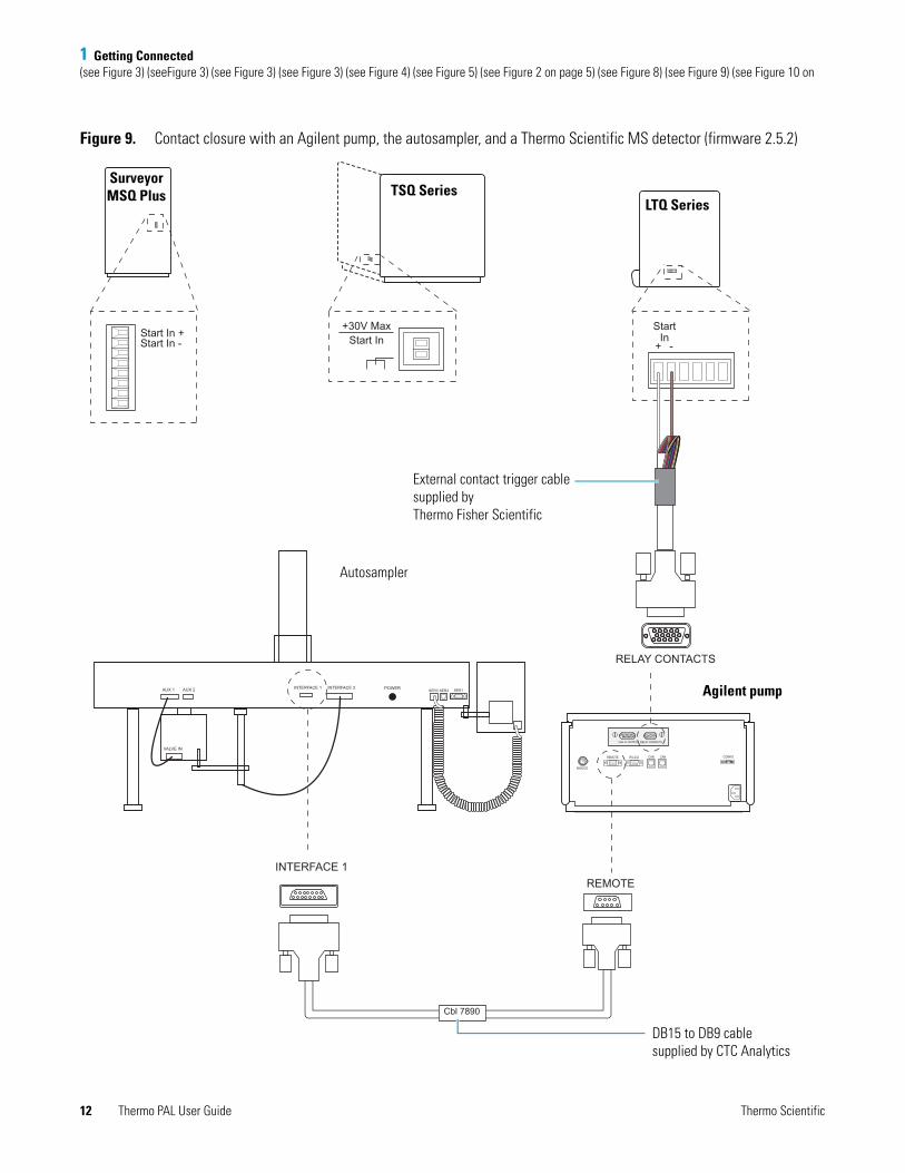
Figure 9. Contact closure with an Agilent pump, the autosampler, and a Thermo Scientific MS detector (firmware 2.5.2)
StartIn
+ -Start In +Start In -
+30V MaxStart In
VALVE IN
AUX 1 AUX 2 INTERFACE 1 INTERFACE 2 POWER SER1SER2SER3
INTERFACE 1
Cbl 7890
REMOTE
RELAY CONTACTS
REMOTE RS-232 CONFIG
ANALOG
CANCAN
RELAY CONTACTSVIAL- # -OUTPUT
External contact trigger cable supplied byThermo Fisher Scientific
DB15 to DB9 cable supplied by CTC Analytics
Autosampler
Agilent pump
TSQ SeriesLTQ Series
Surveyor MSQ Plus
12 Thermo PAL User Guide Thermo Scientific

1 Getting Connected(see Figure 3) (seeFigure 3) (see Figure 3) (see Figure 3) (see Figure 4) (see Figure 5) (see Figure 2 on page 5) (see Figure 8) (see Figure 9) (see Figure 10 on
Figure 10. Contact closure with an Agilent pump, the autosampler, and a Thermo Scientific MS detector (firmware 4.1.2)
REMOTE RS-232 CONFIG
ANALOG
CANCAN
VIAL- # -OUTPUT RELAY CONTACTS
AUX 2 POWER FUSEAUX 1INTERFACE 2INTERFACE 1TERMINAL SER1 LAN MODBUS BUZZER WASHSTATION
LED
StartIn
+ -Start In +Start In - +30V Max
Start In
RELAY CONTACTS
Cbl 7890
REMOTEINTERFACE 1
TSQ SeriesLTQ Series
Surveyor MSQ Plus
OR OR
External contact trigger cable supplied by Thermo Fisher Scientific
Agilent pump
DB15 to DB9 cable supplied by CTC Analytics
Autosampler
Thermo Scientific Thermo PAL User Guide 13

1 Getting ConnectedConnecting the PAL to the Data System Computer
Connecting the PAL to the Data System Computer To connect the PAL to the data system computer
Using the serial cable that is supplied with the autosampler, connect the SER 1 port on the back panel of the autosampler to the serial port on the back panel of the data system computer (see Figure 11 and Figure 12).(see Figure 11)
Figure 11. Data system connection (firmware 2.5.2)
Figure 12. Data system connection (firmware 4.1.2)
POWERINTERFACE SER2SER3 SER1WASHSTATION
BUZZERLEDAUX
Data system computer
Autosampler
DB9 to DB9 serial cable
AUX 2 POWER FUSEAUX 1INTERFACE 2INTERFACE 1TERMINAL SER1 LAN MODBUS BUZZER WASHSTATION
LED
Autosampler
Data system computer
DB9 to DB9 serial cable
14 Thermo PAL User Guide Thermo Scientific

2
Getting Started
This chapter describes how to add the autosampler to the Xcalibur instrument configuration, how to specify the available tray types from the PAL control terminal, and how to specify the injection parameters for the autosampler from the Xcalibur data system.
Adding the Autosampler to the Xcalibur Instrument ConfigurationThe Thermo PAL device driver provides control of the autosampler from the Xcalibur data system. To control the autosampler from the data system, add the autosampler to the Xcalibur instrument configuration and specify the data system COM port that the autosampler is connected to.
Specifying the Configuration Options
This section provides information about how to specify configuration options for the autosampler.
To specify the configuration options for the autosampler
1. Open the Instrument Configuration window from the computer desktop as follows:
For Xcalibur 2.1.0 or later versions, choose Start > All Programs > Thermo Foundation 1.0 > Instrument Configuration.
The Unloading Device Drivers dialog box appears, followed by the Thermo Foundation Instrument Configuration window (see Figure 12).
Contents
• Adding the Autosampler to the Xcalibur Instrument Configuration
• Using the Autosampler Control Terminal
• Specifying the Instrument Method Parameters for the Autosampler
Thermo Scientific Thermo PAL User Guide 15

2 Getting StartedAdding the Autosampler to the Xcalibur Instrument Configuration
Figure 12. Thermo Foundation Instrument Configuration window
2. In the Device Types list, select All.
3. In the Available Devices list, double-click the autosampler.
A copy of the Thermo Pal icon appears in the Configured Devices list.
4. In the Configured Devices list, double-click (Thermal PAL).
The Pal Configuration dialog box appears (see Figure 13).
16 Thermo PAL User Guide Thermo Scientific

2 Getting StartedAdding the Autosampler to the Xcalibur Instrument Configuration
Figure 13. Pal Configuration dialog box
5. Select the data system computer Com port that the autosampler is connected to:
a. In the Com Port list, select the Com port that the autosampler is connected to. Or, click Auto Select.
b. If you have already connected the autosampler to the data system computer, click Check to verify the connection.
6. To shorten the time between injections, select the Enable check box under Look Ahead Injections.
When you enable Look Ahead Injections, the autosampler sets up for the next injection during the current run. The setup for the next injection involves carrying out the steps up to, but not including, the injection.
7. To make the Method Template and Macro Editor dialog boxes available in the Instrument Setup window, select the Enable check box under Method Template\Macro Editor.
Note The autoselect feature works only if the autosampler is connected to the data system computer and turned on.
Tip Do not modify or delete a sequence while the data system is running with the Look Ahead Injections enabled. Use the stop function to finish the current injection before you modify or delete a sequence.
Thermo Scientific Thermo PAL User Guide 17

2 Getting StartedAdding the Autosampler to the Xcalibur Instrument Configuration
8. In the Cycle Composer Macro Importer area, import the macros that you plan to use to create injection methods:
a. In the Import Path box, type the location where the macros reside. Or, click Browse to locate the directory that contains the appropriate macros.
b. In the Overwrite Existing Macros list, make one of the following selections:
• Never. The autosampler does not import the specified macro if it has the same file name as an existing macro.
• Ask. The autosampler asks you if you want to overwrite existing macros.
• Always. Imported macros overwrite existing macros.
c. Click Import to import the macros.
9. In the Active Trays area, select the trays that you want to use.
You can use trays that have a Yes in the Allow Use column. Clicking the tray name clears the Allow Use cell and removes the tray from the list of available trays in the Xcalibur data system.
10. To accept the configuration settings and close the Pal Configuration dialog box, click OK.
11. Configure the other instruments of your LC/MS system, such as the LC pump and the mass spectrometer.
12. In the Thermo Foundation Instrument Configuration window, click Done.
PAL Configuration Parameters
Use the Pal Configuration dialog box to select the PC Com port where the autosampler is connected, specify macros to import, and select sample trays or stacks.
IMPORTANT Use the autosampler control terminal to specify the tray information. You can change the tray information when you are controlling the autosampler from the Xcalibur data system, but these changes are temporary. When you close and reopen the Xcalibur data system, the tray information resets to the autosampler control terminal settings.
Table 4. Pal Configuration dialog box parameters (Sheet 1 of 2)
Parameter Description
Communications
Com Port Select the computer port where you plug the autosampler communication cable.
18 Thermo PAL User Guide Thermo Scientific
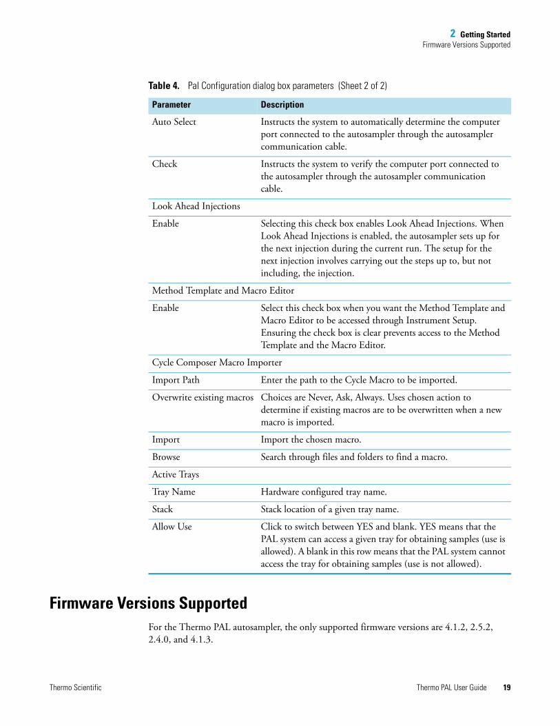
2 Getting StartedFirmware Versions Supported
Firmware Versions SupportedFor the Thermo PAL autosampler, the only supported firmware versions are 4.1.2, 2.5.2, 2.4.0, and 4.1.3.
Auto Select Instructs the system to automatically determine the computer port connected to the autosampler through the autosampler communication cable.
Check Instructs the system to verify the computer port connected to the autosampler through the autosampler communication cable.
Look Ahead Injections
Enable Selecting this check box enables Look Ahead Injections. When Look Ahead Injections is enabled, the autosampler sets up for the next injection during the current run. The setup for the next injection involves carrying out the steps up to, but not including, the injection.
Method Template and Macro Editor
Enable Select this check box when you want the Method Template and Macro Editor to be accessed through Instrument Setup. Ensuring the check box is clear prevents access to the Method Template and the Macro Editor.
Cycle Composer Macro Importer
Import Path Enter the path to the Cycle Macro to be imported.
Overwrite existing macros Choices are Never, Ask, Always. Uses chosen action to determine if existing macros are to be overwritten when a new macro is imported.
Import Import the chosen macro.
Browse Search through files and folders to find a macro.
Active Trays
Tray Name Hardware configured tray name.
Stack Stack location of a given tray name.
Allow Use Click to switch between YES and blank. YES means that the PAL system can access a given tray for obtaining samples (use is allowed). A blank in this row means that the PAL system cannot access the tray for obtaining samples (use is not allowed).
Table 4. Pal Configuration dialog box parameters (Sheet 2 of 2)
Parameter Description
Thermo Scientific Thermo PAL User Guide 19

2 Getting StartedUsing the Autosampler Control Terminal
If you need more fimware information, please contact a local sales person for help.
Using the Autosampler Control TerminalFor general information on using the autosampler control terminal, refer to the CTC PAL System User Manual.
To select the sample trays and to change the default pulse time setting to 4.0 seconds, follow these procedures:
• Selecting the Tray Type
• Changing the Pulse Time Setting
20 Thermo PAL User Guide Thermo Scientific
2 Getting StartedUsing the Autosampler Control Terminal
Selecting the Tray Type
To select the tray type
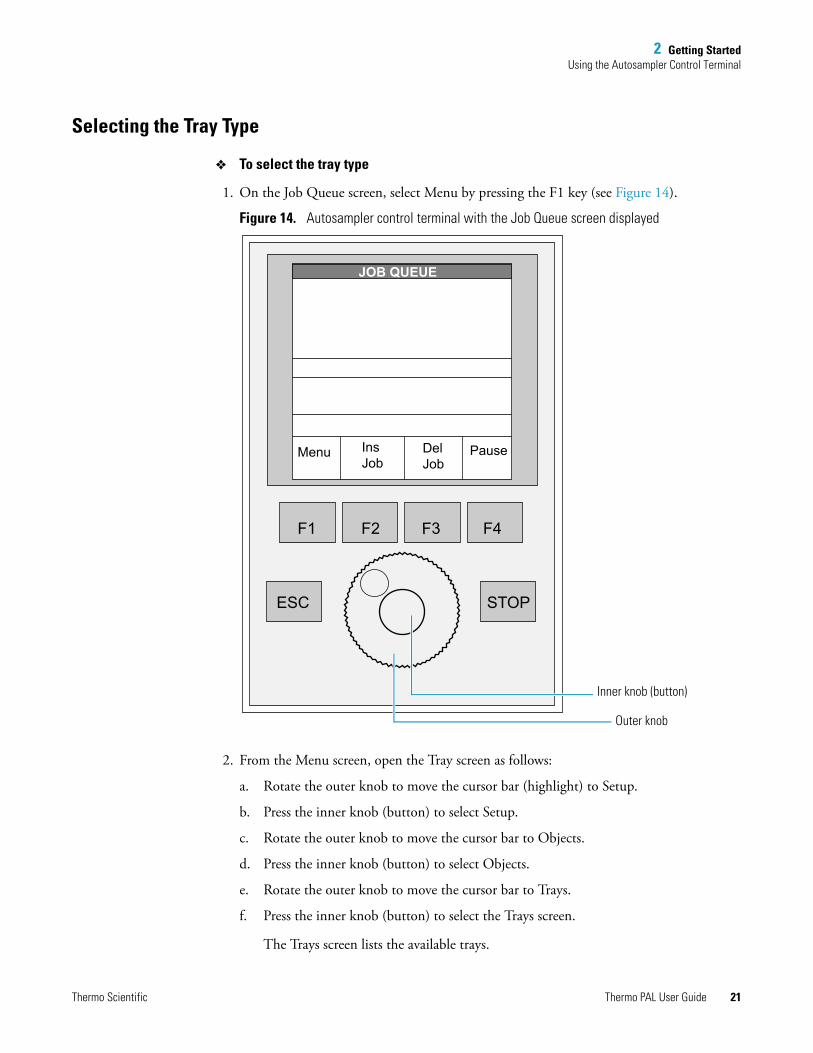
1. On the Job Queue screen, select Menu by pressing the F1 key (see Figure 14).
Figure 14. Autosampler control terminal with the Job Queue screen displayed
2. From the Menu screen, open the Tray screen as follows:
a. Rotate the outer knob to move the cursor bar (highlight) to Setup.
b. Press the inner knob (button) to select Setup.
c. Rotate the outer knob to move the cursor bar to Objects.
d. Press the inner knob (button) to select Objects.
e. Rotate the outer knob to move the cursor bar to Trays.
f. Press the inner knob (button) to select the Trays screen.
The Trays screen lists the available trays.
JOB QUEUE
Menu InsJob
DelJob
Pause
F1 F2 F3 F4
ESC STOP
Outer knob
Inner knob (button)
Thermo Scientific Thermo PAL User Guide 21
2 Getting StartedUsing the Autosampler Control Terminal
3. Select a tray as follows:
a. Rotate the outer knob to move the cursor bar to the tray to be selected.
b. Select the tray by pushing the inner knob (button).
The screen now shows the Tray Type.
c. Make the Tray Type active by pushing the inner knob (button).
The Tray Type is highlighted.
d. Rotate the outer knob to select the tray type. Select NONE if no tray is present (rotate the outer knob until NONE appears as the Tray Type).
e. Push the inner knob (button) to select this tray type.
4. Repeat step 3 for all the trays to be used.
5. Return to the Job Queue screen by pushing the F4 key (Home).
Changing the Pulse Time Setting
To control LC systems with a Thermo Scientific LC pump and an autosampler from the Xcalibur data system, you must change the default pulse time setting for the autosampler from 2 to 4 seconds. The pulse time is the length of time that the autosampler sends an output signal after it makes an injection. The LC pump receives this output signal through the contact closure cable.
IMPORTANT If your LC system contains a Thermo Scientific LC pump and an autosampler, you must change the autosampler’s default pulse time setting. If you leave the default pulse time set to 2 seconds, the status of the LC pump remains at waiting for contact closure after you make an injection.
22 Thermo PAL User Guide Thermo Scientific

2 Getting StartedUsing the Autosampler Control Terminal
Change the pulse time setting to 4.0 seconds from the Injected screen (see Figure 15).
Figure 15. Menu path to Injected screen
To change the pulse time setting
1. Open the Injected screen as follows:
a. On the Job Queue screen, select Menu by pressing the F1 key (see Figure 14).
b. Rotate the outer knob to move the cursor bar (highlight) to Setup, and then press the inner knob (button). The Setup screen appears.
c. Rotate the outer knob to move the cursor bar (highlight) to Objects, and then press the inner knob (button). The Objects screen appears.
d. Rotate the outer knob to move the cursor bar (highlight) to Out Signals, and then press the inner knob (button). The Out Signals screen appears.
e. Rotate the outer knob to move the cursor bar (highlight) to Injected, and then press the inner knob (button). The Injected screen appears (see Figure 15).
2. Rotate the outer knob to move the cursor bar (highlight) to Pulse time, and then press the inner knob (button). The time cell is highlighted.
3. Rotate the outer knob to change the pulse time to 4.0 seconds, and then press the inner knob (button) to set this selection as the default.
4. Return to the Job Queue screen by pushing the F4 key (Home).
Menu
Setup
Objects
Out Signals
Injected
DestinationPulse Time
SW-Out1
Injected
SetDeflt
HomeOms...9.9s
4.0 s
Thermo Scientific Thermo PAL User Guide 23
2 Getting StartedSpecifying the Instrument Method Parameters for the Autosampler
Specifying the Instrument Method Parameters for the AutosamplerTo inject a sample set automatically, you must create an instrument method that contains the chromatographic conditions and mass spectrometer data acquisition settings, and then create an acquisition sequence that specifies the instrument method and vial location for each run. This section describes how to specify the basic instrument method parameters for the autosampler. For information about creating acquisition sequences, refer to the Sequence Setup view Help.
Creating an Instrument Method
This section provides information about how to create an instrument method.
To specify the instrument method parameters for the autosampler
1. Open the Xcalibur data system from the computer desktop as follows:
For Xcalibur version 2.1.0 or later, choose Start > All Programs > Thermo Xcalibur > Xcalibur.
The Roadmap Home Page appears.
2. Click (Instrument Setup).
The Instrument Setup window appears with the configured devices displayed in the view bar (see Figure 16). By default, the view for the first device is open, as indicated by a bright green triangle in the lower-right corner of the device.
24 Thermo PAL User Guide Thermo Scientific

2 Getting StartedSpecifying the Instrument Method Parameters for the Autosampler
Figure 16. Instrument Setup window
3. In the view bar, click (Thermal PAL).
The Method Setup page for the autosampler appears (see Figure 17 on page 26).
Bright green triangle
Thermo Scientific Thermo PAL User Guide 25

2 Getting StartedSpecifying the Instrument Method Parameters for the Autosampler
26 Thermo PAL User Guide Thermo Scientific
Figure 17. Method Setup page for the autosampler
4. Under Template Selection, click Browse and browse to the folder that contains the autosampler methods (*.pme).
For a standard installation, the folder that contains the autosampler method is located in the following directory (see Figure 18):
drive:\Thermo\Instruments\LC Devices\ThermoPAL\PAL\methods
Bb
2 Getting StartedSpecifying the Instrument Method Parameters for the Autosampler
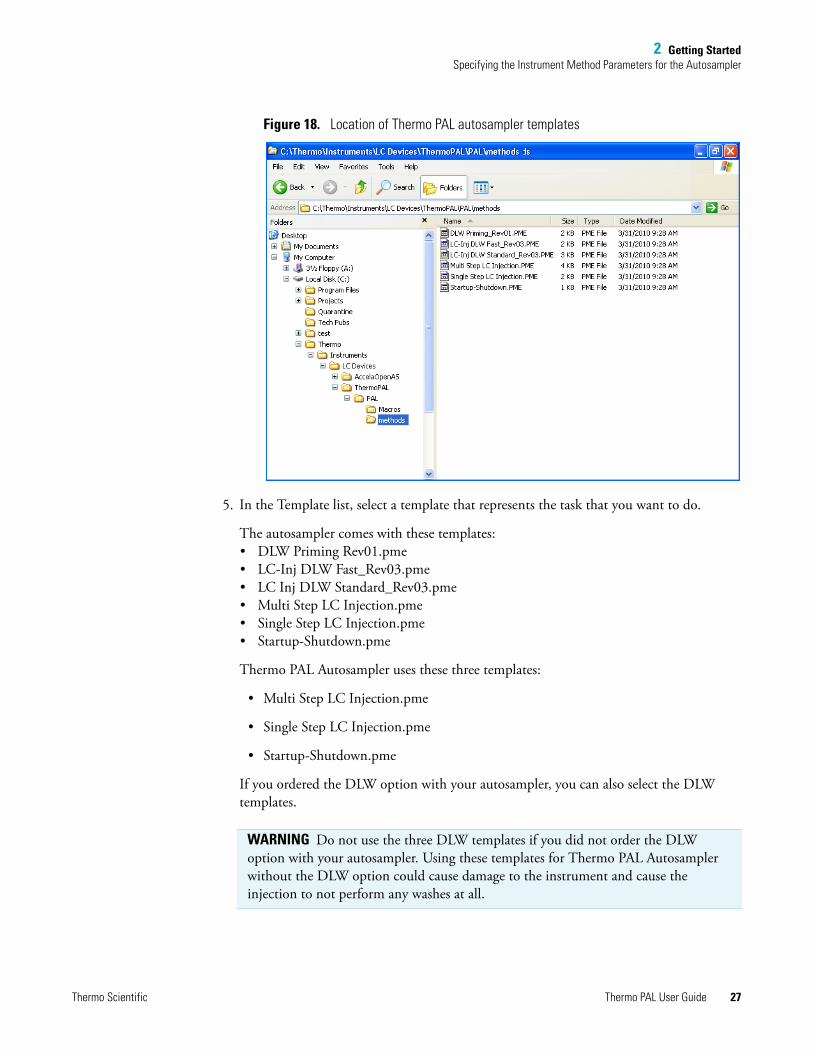
Figure 18. Location of Thermo PAL autosampler templates
5. In the Template list, select a template that represents the task that you want to do.
The autosampler comes with these templates: • DLW Priming Rev01.pme• LC-Inj DLW Fast_Rev03.pme• LC Inj DLW Standard_Rev03.pme• Multi Step LC Injection.pme• Single Step LC Injection.pme• Startup-Shutdown.pme
Thermo PAL Autosampler uses these three templates:
• Multi Step LC Injection.pme
• Single Step LC Injection.pme
• Startup-Shutdown.pme
If you ordered the DLW option with your autosampler, you can also select the DLW templates.
WARNING Do not use the three DLW templates if you did not order the DLW option with your autosampler. Using these templates for Thermo PAL Autosampler without the DLW option could cause damage to the instrument and cause the injection to not perform any washes at all.
Thermo Scientific Thermo PAL User Guide 27
2 Getting StartedSpecifying the Instrument Method Parameters for the Autosampler
In addition to these templates, you can create your own custom templates (see “Using the Template Editor to Create Custom Templates” on page 35). When you store a custom template in the same folder as the standard templates, the template appears in the Template list.
Figure 19 shows the macro sequence and the macro variables for the Single Step LC Injection template.
WARNING If you select a DLW template, make sure the Rear Volume + Injection Volume + Front Volume + 2x Airgap is less than the syringe size. Otherwise it will result in Error 86 (Sringe Volume Out of Range).
28 Thermo PAL User Guide Thermo Scientific
2 Getting StartedSpecifying the Instrument Method Parameters for the Autosampler
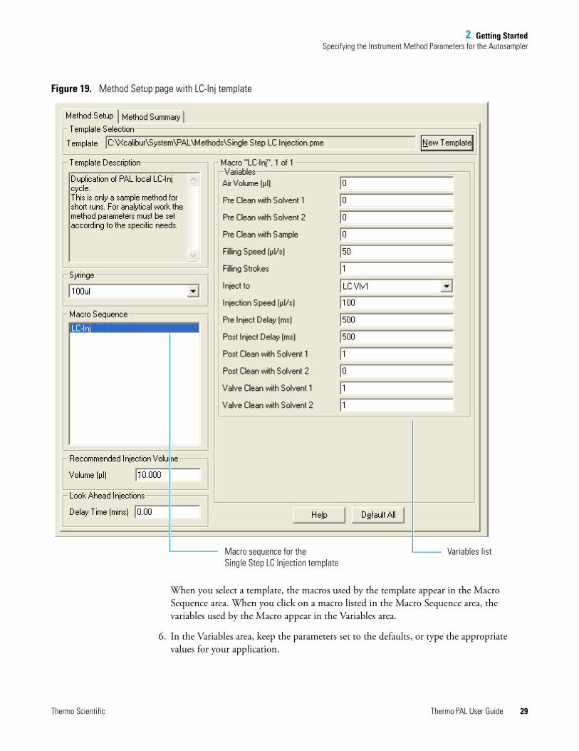
Figure 19. Method Setup page with LC-Inj template
When you select a template, the macros used by the template appear in the Macro Sequence area. When you click on a macro listed in the Macro Sequence area, the variables used by the Macro appear in the Variables area.
6. In the Variables area, keep the parameters set to the defaults, or type the appropriate values for your application.
Macro sequence for the Single Step LC Injection template
Variables list
Thermo Scientific Thermo PAL User Guide 29

2 Getting StartedSpecifying the Instrument Method Parameters for the Autosampler
7. In the Syringe list, select the syringe size that is installed in the autosampler.
The default variable settings for the Single Step LC Injection template and the default setting of 10 μL in the Recommended Injection Volume box are suitable for a 100 μL syringe. Changing the syringe size can change the allowable ranges for the recommended injection volume and the variables specified in the LC-Inj macro.
8. Under Recommended Injection Volume, in the Volume (μL) box, type the volume of sample that you want the autosampler to inject.
The allowable injection volume range is based on the syringe size.
9. Under Look Ahead Injections, if the Delay Time (mins) box is available, type the amount of time that you want the autosampler to wait after it completes the current injection before it starts the next injection.
During a look ahead injection, the autosampler aspirates the sample for the next injection and waits until the end of the current run to inject the sample into the valve. When you add a delay time, the autosampler does not begin the next injection cycle immediately after completing the current injection cycle. If you enter a delay time longer than the method run time, the autosampler begins the next injection at the end of the current run. This means that adding a long delay time does not add additional run time to the method run time, but it does cancel the effect of using the Look Ahead Injections feature.
10. Specify the acquisition parameters for the other devices of your LC or LC/MS instrument.
IMPORTANT Make sure that your syringe selection matches the size of the syringe that is installed in the autosampler.
• If the autosampler is set up to recognize the installed syringe size, an error message appears when you download methods that specify a different syringe size.
• If the autosampler is not set up to recognize the installed syringe and the specified syringe size does not match the actual syringe size, the autosampler does not inject the specified injection volume.
IMPORTANT For partial loop injections (variable volume), make sure that the recommended injection volume is less than half the sample loop size.
Note The Look Ahead Injections feature is available if you selected the Enable check box in the Look Ahead Injections area of the Pal Configuration dialog box.
30 Thermo PAL User Guide Thermo Scientific
2 Getting StartedSpecifying the Instrument Method Parameters for the Autosampler
11. Save the method:
a. From the Instrument Setup window menu bar, choose File > Save As.
The Save As dialog box appears.
b. Select an appropriate file location for the method.
c. In the File name box, type an appropriate name for the method.
d. Click Save. The File Summary Information dialog box appears.
e. (Optional) In the Comment box, type additional information about the method.
f. Click OK.
Xcalibur (or other Thermo Scientific data acquisition applications such as LCquan) stores the method as a *.meth file in the specified file location.
Instrument Setup Parameters
Use the Method Setup page to specify instrument method parameters for the autosampler.
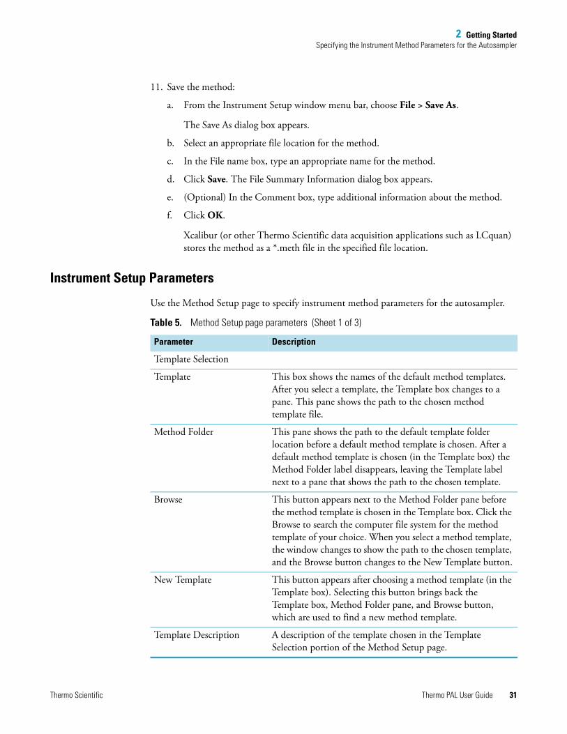
Table 5. Method Setup page parameters (Sheet 1 of 3)
Parameter Description
Template Selection
Template This box shows the names of the default method templates. After you select a template, the Template box changes to a pane. This pane shows the path to the chosen method template file.
Method Folder This pane shows the path to the default template folder location before a default method template is chosen. After a default method template is chosen (in the Template box) the Method Folder label disappears, leaving the Template label next to a pane that shows the path to the chosen template.
Browse This button appears next to the Method Folder pane before the method template is chosen in the Template box. Click the Browse to search the computer file system for the method template of your choice. When you select a method template, the window changes to show the path to the chosen template, and the Browse button changes to the New Template button.
New Template This button appears after choosing a method template (in the Template box). Selecting this button brings back the Template box, Method Folder pane, and Browse button, which are used to find a new method template.
Template Description A description of the template chosen in the Template Selection portion of the Method Setup page.
Thermo Scientific Thermo PAL User Guide 31

2 Getting StartedSpecifying the Instrument Method Parameters for the Autosampler
Syringe This list contains the allowed syringe volumes. Select the appropriate syringe volume.
Macro Sequence Displays the sequence of macros that make up the method chosen in the Template window. Select a macro name to be displayed in the Macro area; its variables also appear in the Variables area.
Recommended Injection Volume
Volume (μl) • When you select an instrument method for use to generate a new sequence (on the Xcalibur Home Page), the injection volume is set to what is entered in this box.
• When "From AS" (From Auto Sampler) is specified in the LCquan injection volume sequence cell, the CTC PAL autosampler uses the volume in this box when you submit the LCquan sequence for acquisition.
Look Ahead Injections
Delay Time (mins) Enter the Delay Time (in minutes) between injections when using the Look Ahead feature. You enable the Look Ahead Injections option from the Pal Configuration dialog box. When you enable this option, the next Look Ahead Injection is delayed the amount of time entered in this box. The delay time countdown begins at the completion of any post-injection steps. This prevents a sample from being held in the injection syringe for the duration of the current run. If the entered Delay Time is too long, or the current run ends prematurely, the entered Delay Time is canceled and the next injection commences in the normal manner.
Macro The Macro area shows the name of the macro selected in the Macro Sequence pane. The sequence number (x) of the selected macro out of the total number of macros (y) in the Macro Sequence is also displayed next to the name of the selected macro (Macro "name", x of y). This area also lists the variables associated with the macro chosen in the Macro Sequence pane.
Table 5. Method Setup page parameters (Sheet 2 of 3)
Parameter Description
32 Thermo PAL User Guide Thermo Scientific
2 Getting StartedViewing the Method Summary
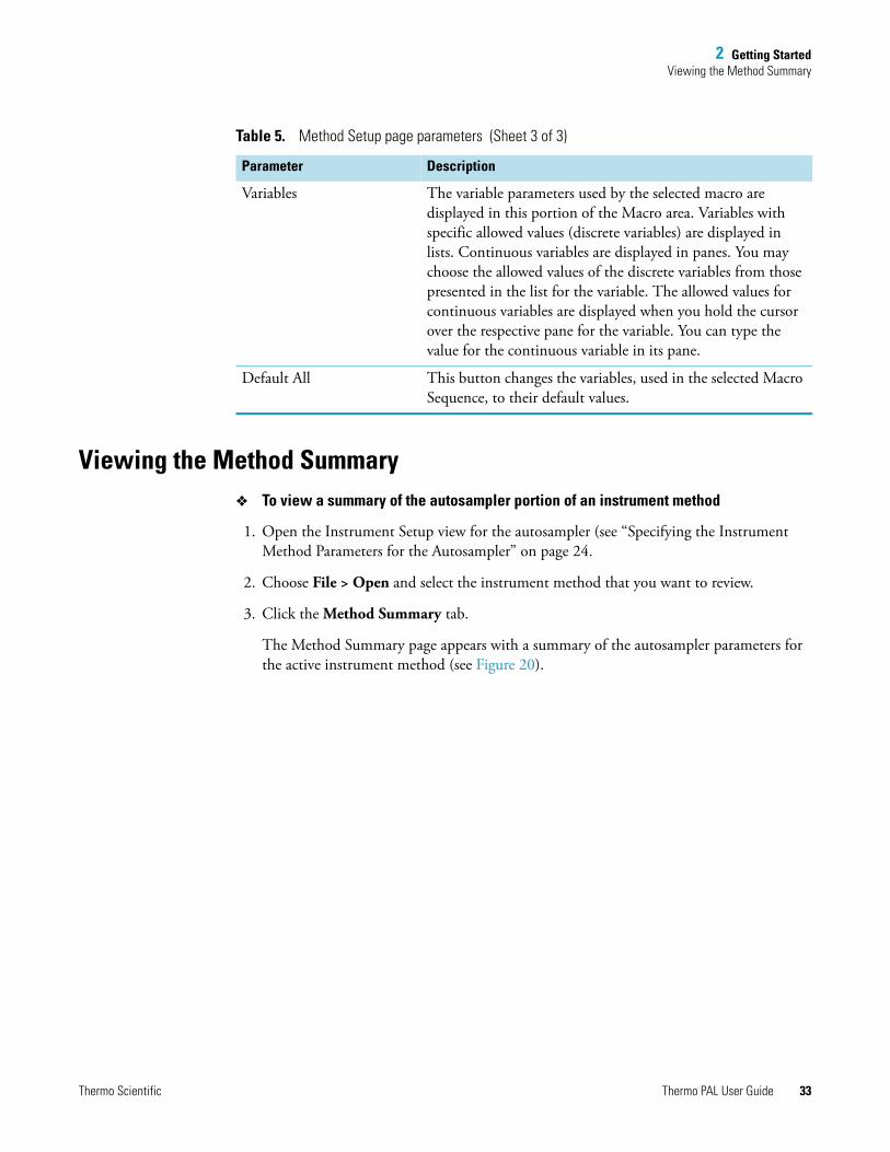
Viewing the Method Summary To view a summary of the autosampler portion of an instrument method
1. Open the Instrument Setup view for the autosampler (see “Specifying the Instrument Method Parameters for the Autosampler” on page 24.
2. Choose File > Open and select the instrument method that you want to review.
3. Click the Method Summary tab.
The Method Summary page appears with a summary of the autosampler parameters for the active instrument method (see Figure 20).
Variables The variable parameters used by the selected macro are displayed in this portion of the Macro area. Variables with specific allowed values (discrete variables) are displayed in lists. Continuous variables are displayed in panes. You may choose the allowed values of the discrete variables from those presented in the list for the variable. The allowed values for continuous variables are displayed when you hold the cursor over the respective pane for the variable. You can type the value for the continuous variable in its pane.
Default All This button changes the variables, used in the selected Macro Sequence, to their default values.
Table 5. Method Setup page parameters (Sheet 3 of 3)
Parameter Description
Thermo Scientific Thermo PAL User Guide 33

2 Getting StartedViewing the Method Summary
Figure 20. Method Summary page
Method Summary
Use the Method Summary page to view the details of the Macro Sequence that makes up an autosampler Method or Template.
The contents of the Method Summary/Template Summary page is read-only.
34 Thermo PAL User Guide Thermo Scientific
3
Creating Custom Templates and Macros
This chapter describes how to create custom templates and macros.
Using the Template Editor to Create Custom TemplatesThree standard templates are provided with the autosampler. To create a custom template, use the Template Editor dialog box.
Creating a Custom Template
This section provides information about how to create a custom template.
To create a custom template
1. Open the Template Editor page as follows:
a. Open the Instrument Setup view for the autosampler (see “Specifying the Instrument Method Parameters for the Autosampler” on page 24).
b. From the menu bar, choose Pal Auto Sampler > Template\Macro Editor.
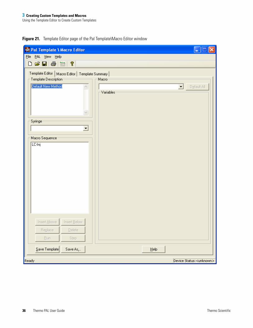
The Template Editor page of the Pal Template\Macro Editor window appears (see Figure 21).
Contents
• Using the Template Editor to Create Custom Templates
• Testing a Custom Template
• Viewing the Template Summary
• Standard Macros
• Using the Macro Editor to Create Custom Macros
• Defining Variables
Thermo Scientific Thermo PAL User Guide 35
3 Creating Custom Templates and MacrosUsing the Template Editor to Create Custom Templates
Figure 21. Template Editor page of the Pal Template\Macro Editor window
36 Thermo PAL User Guide Thermo Scientific
3 Creating Custom Templates and MacrosUsing the Template Editor to Create Custom Templates
2. (Optional) In the Template Description box, type a description of your custom template.
3. In the Syringe list, select the appropriate syringe size to be specified in the template.
4. Add macros to the template as follows:
a. Under Macro, select a macro from the list.
The Insert Above and Insert Below buttons become available.
b. Click Insert Above or Insert Below.
The selected macro appears in the Macro Sequence list.
5. Delete macros from the Macro Sequence list as follows:
a. Select the macro that you want to delete from the Macro Sequence list.
b. Click Delete.
6. Replace a macro in the Macro Sequence list as follows:
a. Under Macro, select a macro from the list.
b. Select the macro that you want to replace in the Macro Sequence list.
c. Click Replace.
7. Save the template:
a. Click Save As.
The Save As dialog box appears.
b. Select a file location.
c. In the File name box, type an appropriate name.
d. Click Save.
The autosampler saves the template with the file extension *.pme.
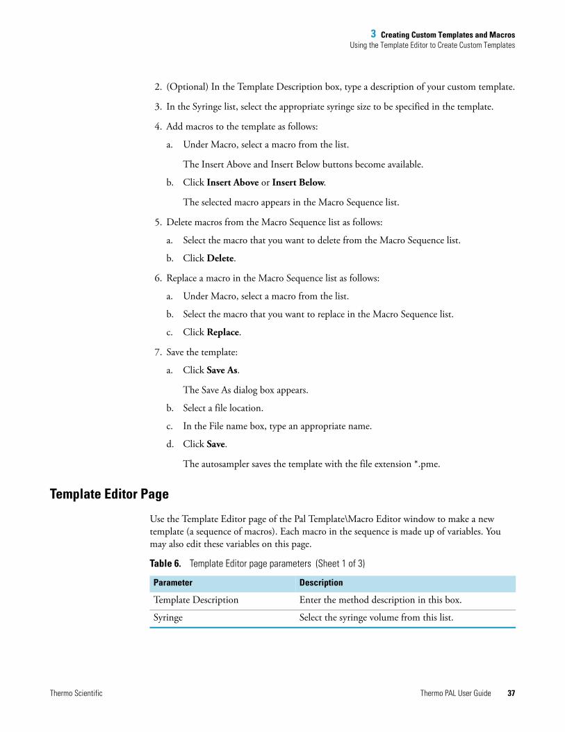
Template Editor Page
Use the Template Editor page of the Pal Template\Macro Editor window to make a new template (a sequence of macros). Each macro in the sequence is made up of variables. You may also edit these variables on this page.
Table 6. Template Editor page parameters (Sheet 1 of 3)
Parameter Description
Template Description Enter the method description in this box.
Syringe Select the syringe volume from this list.
Thermo Scientific Thermo PAL User Guide 37
3 Creating Custom Templates and MacrosUsing the Template Editor to Create Custom Templates
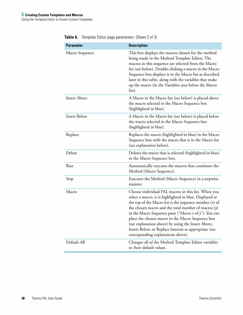
Macro Sequence This box displays the macros chosen for the method being made in the Method Template Editor. The macros in this sequence are selected from the Macro list (see below). Double-clicking a macro in the Macro Sequence box displays it in the Macro list as described later in this table, along with the variables that make up the macro (in the Variables area below the Macro list).
Insert Above A Macro in the Macro list (see below) is placed above the macro selected in the Macro Sequence box (highlighted in blue).
Insert Below A Macro in the Macro list (see below) is placed below the macro selected in the Macro Sequence box (highlighted in blue).
Replace Replaces the macro (highlighted in blue) in the Macro Sequence box with the macro that is in the Macro list (see explanation below).
Delete Deletes the macro that is selected (highlighted in blue) in the Macro Sequence box.
Run Automatically executes the macros that constitute the Method (Macro Sequence).
Step Executes the Method (Macro Sequence) in a stepwise manner.
Macro Choose individual PAL macros in this list. When you select a macro, it is highlighted in blue. Displayed at the top of the Macro list is the sequence number (x) of the chosen macro and the total number of macros (y) in the Macro Sequence pane ("Macro x of y"). You can place the chosen macro in the Macro Sequence box (see explanation above) by using the Insert Above, Insert Below, or Replace buttons as appropriate (see corresponding explanations above).
Default All Changes all of the Method Template Editor variables to their default values.
Table 6. Template Editor page parameters (Sheet 2 of 3)
Parameter Description
38 Thermo PAL User Guide Thermo Scientific

3 Creating Custom Templates and MacrosTesting a Custom Template
Testing a Custom TemplateThis section provides information about testing a custom template.
Using the Template Editor Dialog Box to Test a Custom Template
You can test a custom template from the Template Editor dialog box.
To test your new template step by step
1. If the Template Editor dialog box is closed, open it.
2. Open the template that you want to review by choosing File > Open Method Template.
The default path to open a template is as follows:drive:\Thermo\Instruments\LC Devices\ThermoPAL\PAL\methods
Variables The variables that make up the macro in the Macro list are displayed in this area. Variables with specific allowed values (discrete variables) are displayed in lists. Continuous variables are displayed in boxes. You may choose the allowed values of discrete variables from those presented in the list for the variable. The allowed values for continuous variables are displayed when you hold the cursor over the respective box for the variable. Then, choose the appropriate value for the continuous variable to type in its box.
Save Template Saves the Method Template under the current file name (overwrites the current file).
Save As Saves the Method Template under a new file name or in a new location that you type in the Save As dialog box.
Table 6. Template Editor page parameters (Sheet 3 of 3)
Parameter Description
Thermo Scientific Thermo PAL User Guide 39

3 Creating Custom Templates and MacrosTesting a Custom Template
3. Click Step.
The Run Auto Sampler Method In Step Mode appears (see Figure 22).
Figure 22. Run Auto Sampler Method In Step Mode dialog box
4. Make the appropriate entries and selections:
• Under Trays, select the appropriate trays.
• Under Vial Index, type an appropriate vial location for the template you are testing.
• Under Volume, type the volume that you want to inject.
• In the Injection Per Vial box, type the number of injections that you want to make from each vial.
5. Click Run.
The autosampler performs the actions specified in the template, step-by-step. At the completion of each step, the autosampler pauses the injection sequence and prompts you with the Pal Method Editor dialog box (see Figure 23).
Figure 23. Pal Method Editor dialog box
40 Thermo PAL User Guide Thermo Scientific

3 Creating Custom Templates and MacrosTesting a Custom Template
6. Do one of the following:
• To continue stepping through the template, click Step.
• To run the remaining portion of the template, click Run.
• To stop the run, click Stop Run.
To run the complete sequence of macros in the template without pausing
1. If the Template Editor dialog box is closed, open it.
2. If you closed the custom template, choose File > Template > Open.
3. Click Run.
The Run Auto Sampler Method dialog box appears (see Figure 24).
Figure 24. Run Auto Sampler Method dialog box
4. Make the appropriate entries and selections.
5. Click Run.
The autosampler executes the macros listed in the template.
Run Auto Sampler Method Dialog Box
Use the Run Auto Sampler Method dialog box to enter the Methods information required for the PAL autosampler to carry out autosampling.
Thermo Scientific Thermo PAL User Guide 41
3 Creating Custom Templates and MacrosViewing the Template Summary
Viewing the Template Summary To view a summary of a template
1. Open the PAL Template\Macro Editor window (see “Using the Template Editor to Create Custom Templates” on page 35).
2. Open the template that you want to review by choosing File > Open Method Template.
The default path to open a template is as follows:drive:\Thermo\Instruments\LC Devices\ThermoPAL\PAL\methods
3. Click the Template Summary tab.
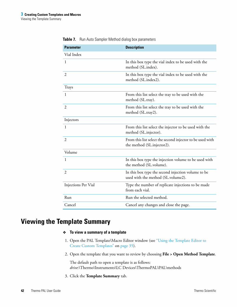
Table 7. Run Auto Sampler Method dialog box parameters
Parameter Description
Vial Index
1 In this box type the vial index to be used with the method (SL.index).
2 In this box type the vial index to be used with the method (SL.index2).
Trays
1 From this list select the tray to be used with the method (SL.tray).
2 From this list select the tray to be used with the method (SL.tray2).
Injectors
1 From this list select the injector to be used with the method (SL.injector).
2 From this list select the second injector to be used with the method (SL.injector2).
Volume
1 In this box type the injection volume to be used with the method (SL.volume).
2 In this box type the second injection volume to be used with the method (SL.volume2).
Injections Per Vial Type the number of replicate injections to be made from each vial.
Run Run the selected method.
Cancel Cancel any changes and close the page.
42 Thermo PAL User Guide Thermo Scientific
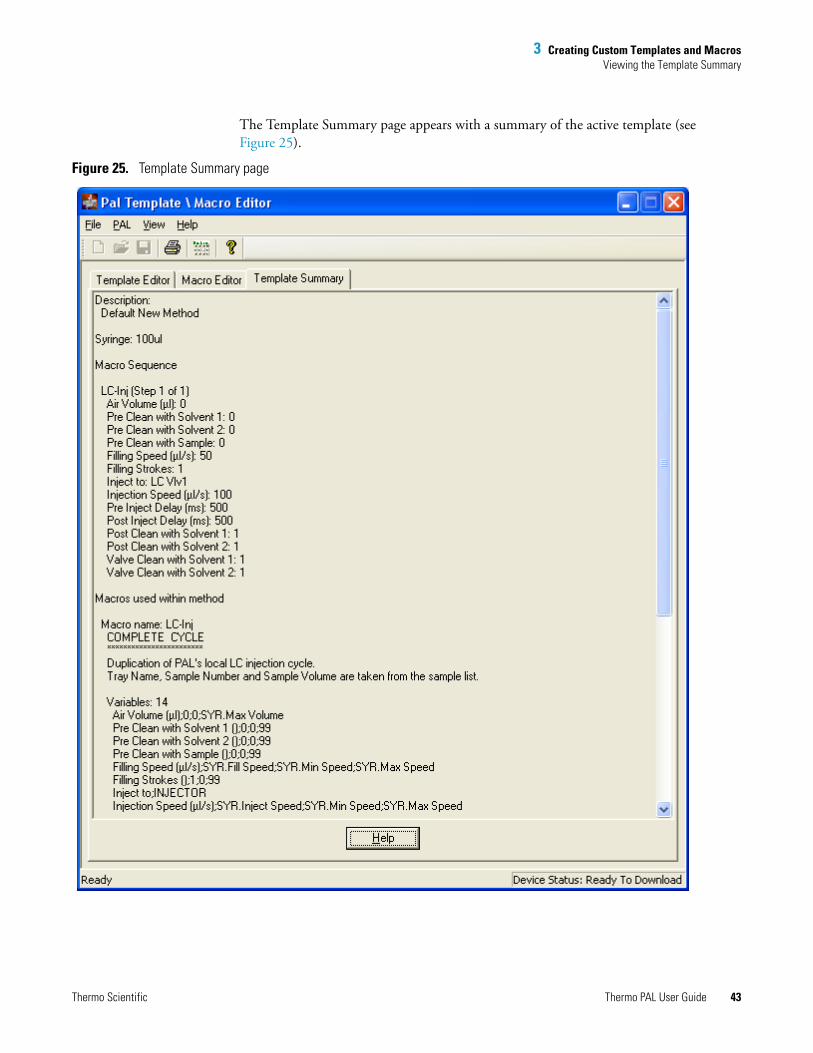
3 Creating Custom Templates and MacrosViewing the Template Summary
The Template Summary page appears with a summary of the active template (see Figure 25).
Figure 25. Template Summary page
Thermo Scientific Thermo PAL User Guide 43
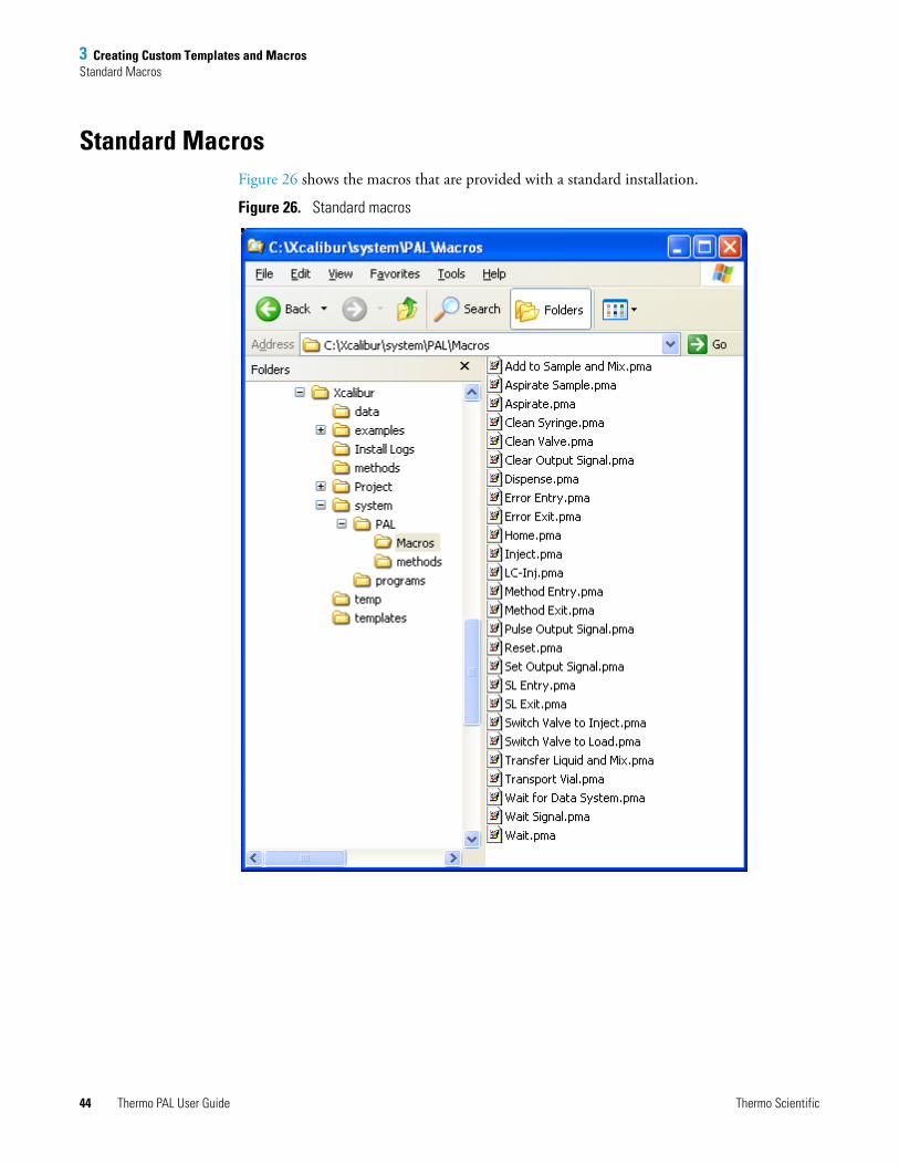
3 Creating Custom Templates and MacrosStandard Macros
Standard MacrosFigure 26 shows the macros that are provided with a standard installation.
Figure 26. Standard macros
44 Thermo PAL User Guide Thermo Scientific
3 Creating Custom Templates and MacrosUsing the Macro Editor to Create Custom Macros
Using the Macro Editor to Create Custom MacrosMacros are the building blocks that you use to create templates.
Creating a Custom Macro
This section provides information about how to create a custom macro.
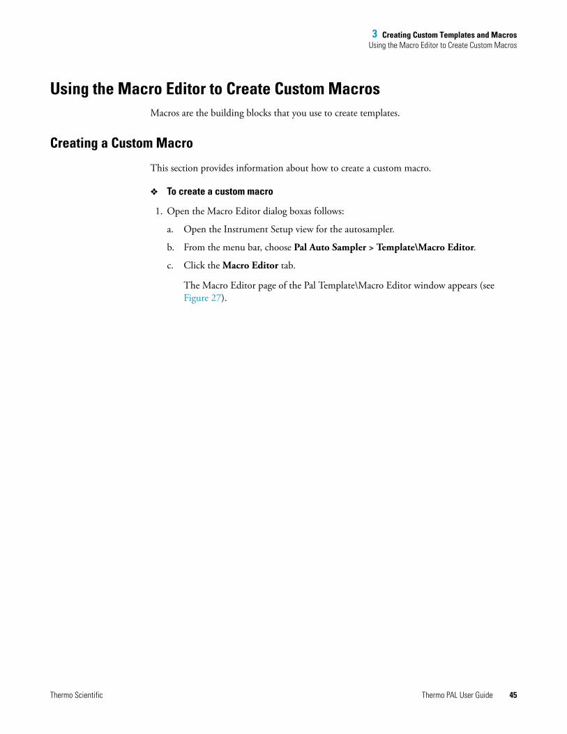
To create a custom macro
1. Open the Macro Editor dialog boxas follows:
a. Open the Instrument Setup view for the autosampler.
b. From the menu bar, choose Pal Auto Sampler > Template\Macro Editor.
c. Click the Macro Editor tab.
The Macro Editor page of the Pal Template\Macro Editor window appears (see Figure 27).
Thermo Scientific Thermo PAL User Guide 45

3 Creating Custom Templates and MacrosUsing the Macro Editor to Create Custom Macros
Figure 27. Macro Editor page of the Template\Macro Editor window
2. Under Macro, select a macro from the list.
The description of the selected macro appears under Macro Description and a list of macro variables appears under Macro Variables.
46 Thermo PAL User Guide Thermo Scientific

3 Creating Custom Templates and MacrosUsing the Macro Editor to Create Custom Macros
3. To add a variable to the macro, click Add.
The Variable Definition dialog box appears.
4. Define the variable (see “Defining Variables” on page 50).
5. Save the macro as follows:
a. Click Save As.
The Save As dialog box appears.
b. Select a file location.
c. In the File name box, type an appropriate name.
d. Click Save.
The autosampler saves the macro with the file extension *.pma.
PAL Template - Macro Editor Page
Use the Macro Editor page of the Pal Template\Macro Editor window to create custom macros.
Table 8. Macro Editor page parameters (Sheet 1 of 3)
Parameter Description
Macro This list displays existing autosampler macros. Select the macro that you want to edit.
Macro Description A description of the macro selected in the Macro list.
Macro Variables Variables used by the macro selected in the Macro list.
Add Adds a new variable to the macro variables. The new variable is defined in an Edit Parameter dialog box that opens when you click Add.
The Edit Parameter dialog box has a check box for the Parameter Type (numeric or object). If you select a numeric Parameter Type, you see a pane for entering the new parameter name, a list for the parameter units, and panes for entering the default value for the parameter along with the lower and upper limits for the parameter. If you select an object Parameter Type, you see a check list of objects that might be represented by the parameter.
Thermo Scientific Thermo PAL User Guide 47

3 Creating Custom Templates and MacrosUsing the Macro Editor to Create Custom Macros
Edit Edits an existing macro variable. The editing is carried out in an Edit Parameter dialog box that opens when you click Edit.
The Edit Parameter dialog box has a check box for the Parameter Type (numeric or object). If you select a numeric Parameter Type, you see a pane in which you enter the new parameter name, a list for the parameter units, and panes in which you enter the default value for the parameter along with the lower and upper limits for the parameter. If you choose an object Parameter Type, you see a check list of objects that may be represented by the parameter.
Delete Deletes the selected Macro Variable.
Command Sequence The sequence of commands that make up the macro selected in the Macro list. Double-clicking one of the commands highlights it in blue and causes its display in the Command area. In the Command area the command parameters are shown in both panes (continuous variables) and lists (discrete variables).
Insert Above The command shown in the Command area is inserted above the command selected (highlighted in blue) in the Command Sequence pane.
Insert Below The command shown in the Command area is inserted below the command selected (highlighted in blue) in the Command Sequence pane.
Replace The command selected (highlighted in blue) in the Command Sequence pane is replaced by the command shown in the Command area.
Delete Deletes the command selected (highlighted in blue) in the Command Sequence pane.
Table 8. Macro Editor page parameters (Sheet 2 of 3)
Parameter Description
48 Thermo PAL User Guide Thermo Scientific
3 Creating Custom Templates and MacrosUsing the Macro Editor to Create Custom Macros
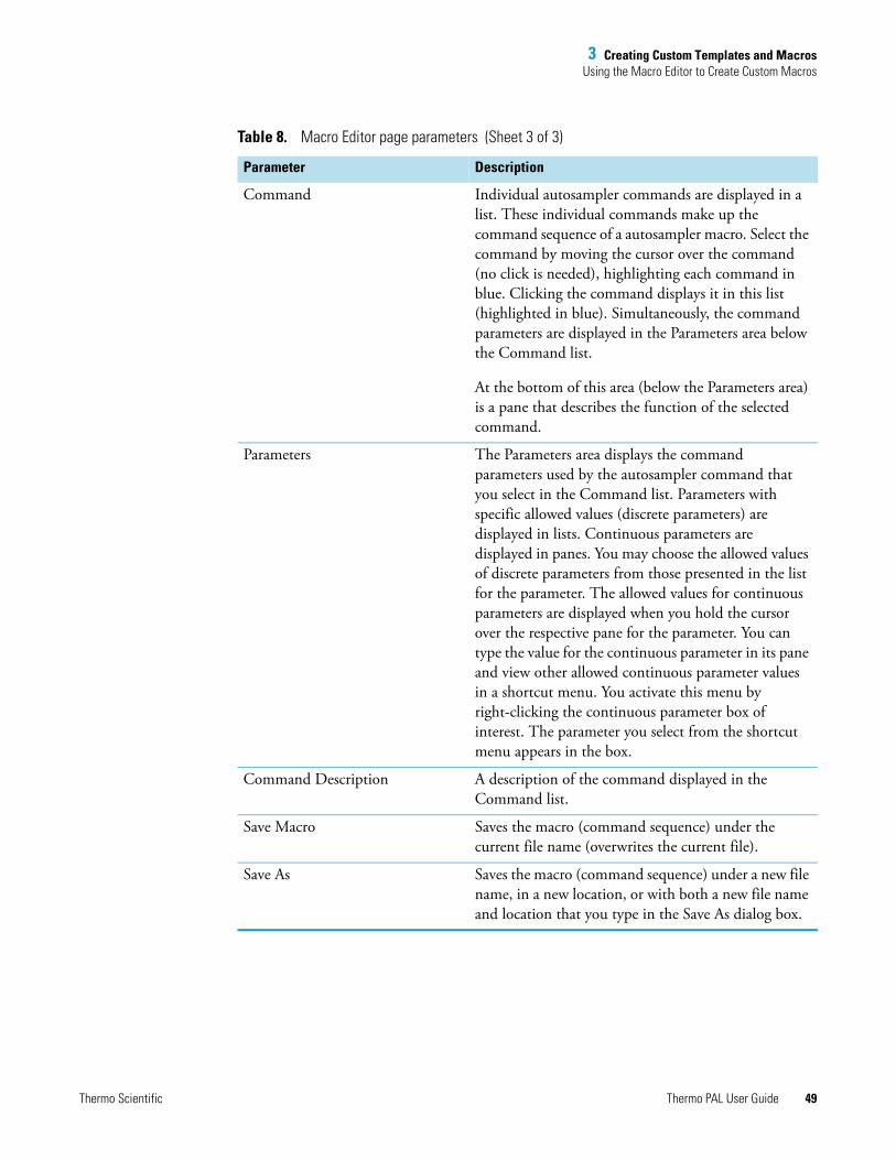
Command Individual autosampler commands are displayed in a list. These individual commands make up the command sequence of a autosampler macro. Select the command by moving the cursor over the command (no click is needed), highlighting each command in blue. Clicking the command displays it in this list (highlighted in blue). Simultaneously, the command parameters are displayed in the Parameters area below the Command list.
At the bottom of this area (below the Parameters area) is a pane that describes the function of the selected command.
Parameters The Parameters area displays the command parameters used by the autosampler command that you select in the Command list. Parameters with specific allowed values (discrete parameters) are displayed in lists. Continuous parameters are displayed in panes. You may choose the allowed values of discrete parameters from those presented in the list for the parameter. The allowed values for continuous parameters are displayed when you hold the cursor over the respective pane for the parameter. You can type the value for the continuous parameter in its pane and view other allowed continuous parameter values in a shortcut menu. You activate this menu by right-clicking the continuous parameter box of interest. The parameter you select from the shortcut menu appears in the box.
Command Description A description of the command displayed in the Command list.
Save Macro Saves the macro (command sequence) under the current file name (overwrites the current file).
Save As Saves the macro (command sequence) under a new file name, in a new location, or with both a new file name and location that you type in the Save As dialog box.
Table 8. Macro Editor page parameters (Sheet 3 of 3)
Parameter Description
Thermo Scientific Thermo PAL User Guide 49

3 Creating Custom Templates and MacrosDefining Variables
Defining VariablesVariables are the building blocks that you use to create macros.
Creating Custom Variables
This section provides information about how to create custom variables.
To create custom variables
1. Open the Macro Editor dialog box as follows:
a. Open the Instrument Setup view for the Accela Open Autosampler (see “Specifying the Instrument Method Parameters for the Autosampler” on page 24).
b. From the menu bar, choose Pal Auto Sampler > Template\Macro Editor.
c. Click the Macro Editor tab.
The Macro Editor page of the Pal Template\Macro Editor window appears (see Figure 27).
2. Click Add.
The Variable Definition dialog box appears (see Figure 28).
Figure 28. Variable Definition dialog box
3. Select a variable type:
• To create a variable that is a numeric value, select the A Number Value option. Then go to step 4.
• To create an object variable, select the An Object option. A list of objects appears. Go to step 5.
50 Thermo PAL User Guide Thermo Scientific
3 Creating Custom Templates and MacrosDefining Variables
4. Complete the definition of a numeric variable as follows:
a. In the Variable Name box, type an appropriate name.
b. In the Variable Units list, select a unit of measure.
c. In the Default Value box, type a default value for the variable.
d. In the Lower Limit box, type a lower limit for the variable.
e. In the Upper Limit box, type an upper limit for the variable.
f. Click OK to save the variable and close the Variable Definition dialog box.
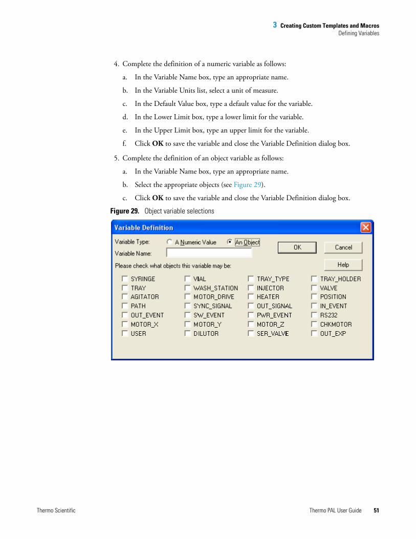
5. Complete the definition of an object variable as follows:
a. In the Variable Name box, type an appropriate name.
b. Select the appropriate objects (see Figure 29).
c. Click OK to save the variable and close the Variable Definition dialog box.
Figure 29. Object variable selections
Thermo Scientific Thermo PAL User Guide 51

3 Creating Custom Templates and MacrosDefining Variables
Variable Definition Dialog Box
Use the Variable Definition dialog box to specify the details of a numerical or object Macro Variable that you want to add or edit in the Macro Variables box.
Table 9. Variable Definition dialog box
Parameter Description
Variable Type
A Numeric Value Select this if the parameter is a numeric value. If you are editing an existing numerical parameter, this box is marked with a black dot.
An Object Select this if the parameter is an object. If you are editing an existing object parameter, this box is marked with a black dot.
Variable Name If you are editing an existing variable, this box shows the name of the variable. Type your choice for the name of the variable if you are adding a new one.
OK Accepts the new Variable Definition or accepts the edits to an existing Variable Definition.
Cancel Deletes changes made in the Variable Definition dialog box.
Numeric Value Variable Type
Variable Units If you are editing an existing variable, this list shows the units for the selected variable. If you are adding a new variable, you may enter units appropriate for that variable. When you click the list arrow, you can select the appropriate units from the options in the list.
Default Value The nominal or center value of the variable.
Lower Limit The lowest acceptable value of the variable.
Upper Limit The highest acceptable value of the variable.
Object Variable Type
Please check what objects this variable may be
Select one or more objects that are described by the variable.
52 Thermo PAL User Guide Thermo Scientific
4
Using the Direct Controls to Operate the Autosampler
This chapter describes how to operate the autosampler from the Direct Control dialog box.
Opening the Direct Control Dialog BoxThe direct control pages for the autosampler are available from the Instrument Setup window and the Tune window.
To open the Direct Control dialog box from the Instrument Setup window
1. In the view bar, click (Thermal PAL).
The Instrument Setup view for the autosampler appears.
2. From the menu bar, choose Pal Auto Sampler > Direct Control.
The Direct Control dialog box appears with the Methods page displayed (see Figure 30 on page 54).
Contents
• Opening the Direct Control Dialog Box
• Making Single Injections from the Tune Window
• Changing the Tray Configuration
• Specifying the Location of the Direct Control Methods
• Wrapping Direct Control Injections with Additional Macros
Thermo Scientific Thermo PAL User Guide 53

4 Using the Direct Controls to Operate the AutosamplerOpening the Direct Control Dialog Box
Figure 30. Direct Control dialog box
To open the Inlet Direct Control dialog box from the Tune window
1. From the menu bar, choose Setup > Inlet Direct Control.
2. Click the Thermo Pal tab.
The Inlet Direct Control dialog box for the autosampler appears with the Methods page displayed. The Inlet Direct Control dialog box has the same functionality as the Direct Control dialog box shown in Figure 30.
54 Thermo PAL User Guide Thermo Scientific
4 Using the Direct Controls to Operate the AutosamplerMaking Single Injections from the Tune Window
Making Single Injections from the Tune WindowYou can make single injections from the Tune window.
To make single injections from the Tune window
1. Open the Tune window for your mass spectrometer.
2. Open the Inlet Direct Control dialog box (see “Opening the Direct Control Dialog Box” on page 53).
3. Specify the location of the methods that you want to use (see “Direct Control - Tray Configuration Page” on page 59).
4. Specify the tray types that are loaded in the autosampler L tray holders (see “Changing the Tray Configuration” on page 58).
5. Click the Methods tab.
The Methods page appears. The Syringe area lists the size of the configured syringe. The Device Status area lists the status of the autosampler.
6. In the Method list, select a method.
A description of the method appears in the Description box (see Figure 31 on page 56). The method list depends on the file locations specified on the Direct Control Configuration page.
Note The visible DLW methods in the Method dropdown list are only available if you have installed the DLW option that comes with your automsampler.
Thermo Scientific Thermo PAL User Guide 55
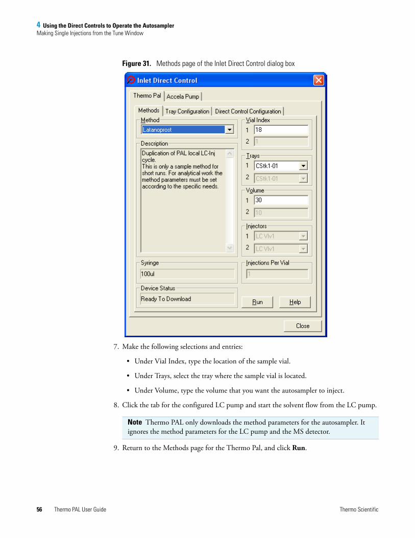
4 Using the Direct Controls to Operate the AutosamplerMaking Single Injections from the Tune Window
Figure 31. Methods page of the Inlet Direct Control dialog box
7. Make the following selections and entries:
• Under Vial Index, type the location of the sample vial.
• Under Trays, select the tray where the sample vial is located.
• Under Volume, type the volume that you want the autosampler to inject.
8. Click the tab for the configured LC pump and start the solvent flow from the LC pump.
9. Return to the Methods page for the Thermo Pal, and click Run.
Note Thermo PAL only downloads the method parameters for the autosampler. It ignores the method parameters for the LC pump and the MS detector.
56 Thermo PAL User Guide Thermo Scientific

4 Using the Direct Controls to Operate the AutosamplerMaking Single Injections from the Tune Window
Direct Control - Methods Page
The Methods page of the Inlet Direct Control dialog box has the following parameters.
Table 10. Methods page parameters
Parameter Description
Method Use this list to select a method file. The visible DLW methods in the Method dropdown list are only available if you have installed the DLW option that comes with your automsampler.
Description This box contains a description of the selected method.
Syringe This box displays the configured syringe.
Device Status This box displays the status of the PAL. Status states
Vial Index
1 In this box type the vial index to be used with the method (SL.index).
2 In this box type the vial index to be used with the method (SL.index2).
Trays
1 From this list select the tray to be used with the method (SL.tray).
2 From this list select the tray to be used with the method (SL.tray2).
Volume
1 In this box type the injection volume to be used with the method (SL.volume).
2 In this box type the second injection volume to be used with the method (SL.volume2).
Injectors
1 From this list select the injector to be used with the method (SL.injector).
2 From this list select the second injector to be used with the method (SL.injector2).
Injections Per Vial Type the number of replicate injections to be made from each vial.
Run Runs the selected method.
Thermo Scientific Thermo PAL User Guide 57

4 Using the Direct Controls to Operate the AutosamplerChanging the Tray Configuration
Changing the Tray ConfigurationUse the Tray Configuration dialog box to specify the tray types to be used for direct control injections while you have the Direct Control dialog box open. The autosampler uses this tray information instead of the tray information specified in the autosampler Control Terminal.
To change the tray configuration
1. Open the Direct Control dialog box (see “Opening the Direct Control Dialog Box” on page 53).
2. Click the Tray Configuration tab.
The Tray Configuration page appears (see Figure 32).
Figure 32. Tray Configuration page
3. In the Tray list, select the tray that you want to modify.
4. In the Type list, select the tray type.
IMPORTANT The autosampler does not store the tray configuration that you specify on the Tray Configuration page of the Direct Control dialog box. When you close the dialog box, the tray configuration resets to the autosampler Control Terminal settings.
58 Thermo PAL User Guide Thermo Scientific

4 Using the Direct Controls to Operate the AutosamplerSpecifying the Location of the Direct Control Methods
Direct Control - Tray Configuration Page
Use the Tray Configuration page in the Direct Control dialog box to enter the Tray Configuration information required for the autosampler to carry out autosampling.
Specifying the Location of the Direct Control MethodsUse the Direct Control Configuration dialog box to specify the location of the methods that you can open in the Methods page of the Direct Control dialog box.
To specify the method folders
1. Open the Direct Control dialog box (see “Opening the Direct Control Dialog Box” on page 53).
2. Click the Direct Control Configuration tab.
The Direct Control Configuration page appears (see Figure 33). By default, the methods that appear in the Method list on the Method page are located in the following directory:
drive:\Xcalibur\Methods
Table 11. Tray Configuration page parameters
Parameter Description
Tray From this list, select the tray location in the three drawer (deep drawer) configuration: tray 1 & 2=drawer #1, tray 3 & 4=drawer #2, tray 5 & 6=drawer #3. Up to six drawers and twelve trays are possible with the shallow drawer configuration.
Type From this list, select the tray type.
Tray Holder Stack 1 and Stack 2 are the allowed values. Tray holders can hold one or more trays. A Stack is a tray holder that is designed to hold microplates. The autosampler firmware determines the type and number.
Vials in X Direction, Vials in Y Direction
Determined by choice of tray type.
Thermo Scientific Thermo PAL User Guide 59
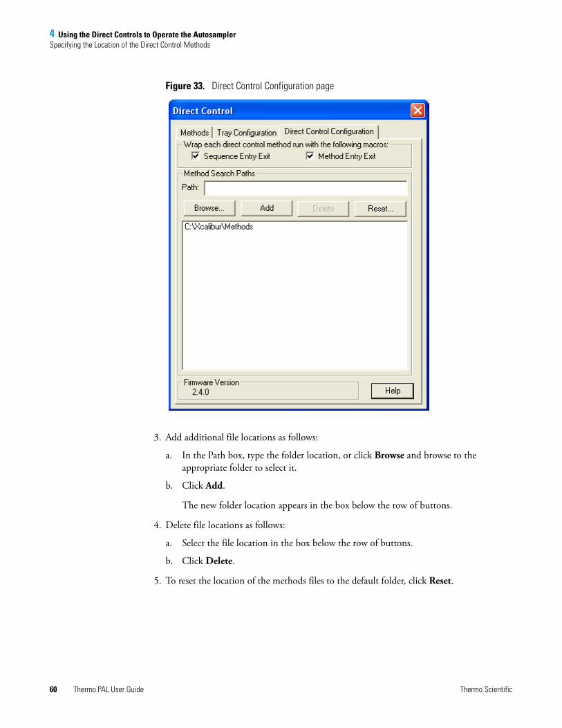
4 Using the Direct Controls to Operate the AutosamplerSpecifying the Location of the Direct Control Methods
Figure 33. Direct Control Configuration page
3. Add additional file locations as follows:
a. In the Path box, type the folder location, or click Browse and browse to the appropriate folder to select it.
b. Click Add.
The new folder location appears in the box below the row of buttons.
4. Delete file locations as follows:
a. Select the file location in the box below the row of buttons.
b. Click Delete.
5. To reset the location of the methods files to the default folder, click Reset.
60 Thermo PAL User Guide Thermo Scientific
4 Using the Direct Controls to Operate the AutosamplerSpecifying the Location of the Direct Control Methods
Direct Control - Direct Control Configuration Page
Use the Direct Control Configuration page in the Direct Control dialog box to enter the Direct Control Configuration information required for the autosampler to carry out autosampling.
Wrap each direct control method run with the following macros.
Table 12. Direct Control Configuration page parameters
Parameter Description
Sequence Entry Exit Use this check box to wrap methods with the sequence list entry and exit macros (SLentry and SLexit).
Method Entry Exit Use this check box to wrap methods with the method entry and exit macros (Method Entry and Method Exit).
Method Search Paths
Path Use this box to specify the extra path you want added to the method search routine.
Browse Use this button to search for a path.
Add Use this button to add the current path to those searched.
Delete Use this button to delete the currently selected path.
Reset Use this button to remove all of the user added paths.
text box This text box displays the directories that the autosampler searches for methods.
Firmware Version Specifies the firmware version downloaded from the autosampler.
Thermo Scientific Thermo PAL User Guide 61

4 Using the Direct Controls to Operate the AutosamplerWrapping Direct Control Injections with Additional Macros
Wrapping Direct Control Injections with Additional MacrosUse the Direct Control Configuration dialog box to specify whether the autosampler is to run the SL Entry and SL Exit, the Method Entry and Method Exit, or all of these macros before and after an injection.
To specify the use of the SL Entry and SL Exit macros
Select the Sequence Entry Exit check box.
To specify the use of the Method Entry and Method Exit macros
Select the Method Entry Exit check box.
62 Thermo PAL User Guide Thermo Scientific
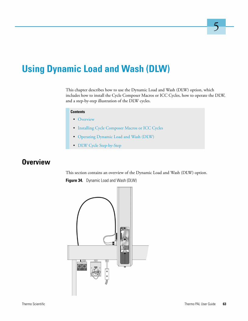
5
Using Dynamic Load and Wash (DLW)
This chapter describes how to use the Dynamic Load and Wash (DLW) option, which includes how to install the Cycle Composer Macros or ICC Cycles, how to operate the DLW, and a step-by-step illustration of the DLW cycles.
OverviewThis section contains an overview of the Dynamic Load and Wash (DLW) option.
Figure 34. Dynamic Load and Wash (DLW)
Contents
• Overview
• Installing Cycle Composer Macros or ICC Cycles
• Operating Dynamic Load and Wash (DLW)
• DLW Cycle Step-by-Step
Thermo Scientific Thermo PAL User Guide 63
5 Using Dynamic Load and Wash (DLW)Installing Cycle Composer Macros or ICC Cycles
The DLW option represents a new wash station concept that combines an injection cycle with wash steps. The linked combination of the two steps, which are usually separate, minimizes cycle time and carryover.
There are two characterizing features for the DLW option:
• The sample solution never contacts the syringe itself; it is held between the holding loop.
• Wash solvents are pumped from back to front into the DLW system to intensely flush all critical parts that are in contact with the sample.
The DLW option consists of two self-priming micro pumps (mounted on a dedicated bracket), and the wetted parts are Ryton™ PPS and Kalrez™ (FFPM). The pump IN ports are connected to the wash solvent bottles and the OUT ports are connected to the DLW manifold, which is part of the assembly of the dedicated DLW syringe holder. A holding loop separates the syringe from the DLW actuator to prevent sample from contacting these parts.
The syringe and holding loop are preloaded with wash solvent #1 at the start. The sample is picked up and remains separated from wash solvent #1 by an air gap. After loading the loop and injection, wash solvent #1 is pushed into the system, followed directly by wash solvent #2 to flush the critical valve paths.
The DLW syringe assembly is moved to the wash station for further cleaning steps and for preparing the syringe and holding loop for the next cycle.
For further details, see “DLW Cycle Step-by-Step” on page 75.
Installing Cycle Composer Macros or ICC CyclesYou can only operate the autosampler DLW option with PAL control software, such as the Thermo PAL driver for the Xcalibur data system, or Cycle Editor for ICC interpretation in another data handling system software.
For software control, three macros or three cycles are provided.
The first of three macros covers the initial and daily priming of the solvent lines and covers a complete injection cycle, a second macro is used for Standard speed with optimized washing possibilities, and the last for a Fast cycle for optimized throughput and less focus on carryover. See Table 13.
For detailed descriptions of all macros (or cycles), see Table 13, Table 14, and Table 15.
64 Thermo PAL User Guide Thermo Scientific

5 Using Dynamic Load and Wash (DLW)Installing Cycle Composer Macros or ICC Cycles
Installing the Cycle Composer Macros or ICC Cycles
The autosampler is shipped with a CD-ROM containing various cycles for the DLW option. Macros for the Xcalibur data system are installed by the LC Devices 2.4 installer.
Copy these macros to your Thermo PAL driver method folder or corresponding folder for application within the integrated system.
To copy cycles to your Cycle Composer
1. Navigate in Windows™ Explorer to the Thermo PAL driver folder. The usual folder location is as follows:
C:\Thermo\Instruments\LC Devices\ThermoPAL\PAL
2. If you wish to add the DLW option macros to an existing method folder, copy the macros (*.pma) and the methods (*.pme) files from the DLW Option folder on the CD-ROM to the method folder.
3. If the PAL system is integrated in a data system software that controls the PAL using the Cycle Editor for PAL ICC interpretation (for example, Analyst™, ChemStation™, Empower™, EZChrom, MassLynx™, Xcalibur), an ICC Cycle is used and not the Cycle Composer Macro.
The cycle extension is *.cyx.
Table 13. The DLW macro definitions
Macro name Macro description
Priming Accela Open For initial and daily routine priming of the solvent lines and DLW manifold. The Clean Time for both wash solvents is a variable for the user to define the intensity of washing.
Standard Injection Accela Open
Standard injection cycle using all possibilities of the DLW option. The injection valve inlet port and the needle are washed with both wash solvents (inside and out). You can add an extra Stator Wash for intensive washing of the injection valve (valve toggle).
Fast Injection Accela Open
Tuned for speed and high-throughput application. It differs from the Standard DLW macro in that some steps are left out to shorten the cycle time.
Note You can convert a Cycle Composer macro to a cycle (extension *.cyx) by using the Cycle Editor software. Conversion is available starting with Cycle Editor version 1.4.0.4.
Note The provided macros are written for standard injection valve drives, which are controlled and activated through the AUX interface.
Thermo Scientific Thermo PAL User Guide 65
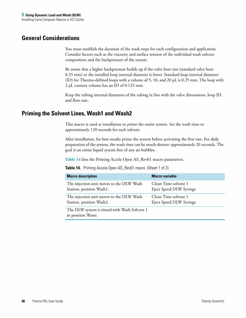
5 Using Dynamic Load and Wash (DLW)Installing Cycle Composer Macros or ICC Cycles
General Considerations
You must establish the duration of the wash steps for each configuration and application. Consider factors such as the viscosity and surface tension of the individual wash solvent composition and the backpressure of the system.
Be aware that a higher backpressure builds up if the valve bore size (standard valve bore 0.25 mm) or the installed loop internal diameter is lower. Standard loop internal diameter (ID) for Thermo-defined loops with a volume of 5, 10, and 20 μL is 0.25 mm. The loop with 2 μL content volume has an ID of 0.125 mm.
Keep the tubing internal diameters of the tubing in line with the valve dimensions, loop ID, and flow rate.
Priming the Solvent Lines, Wash1 and Wash2
This macro is used at installation to prime the entire system. Set the wash time to approximately 120 seconds for each solvent.
After installation, for best results prime the system before activating the first run. For daily preparation of the system, the wash time can be much shorter: approximately 20 seconds. The goal is an entire liquid system free of any air bubbles.
Table 14 lists the Priming Accela Open AS_Rev01 macro parameters.
Table 14. Priming Accela Open AS_Rev01 macro (Sheet 1 of 2)
Macro description Macro variable
The injection unit moves to the DLW Wash Station, position Wash1.
Clean Time solvent 1Eject Speed DLW Syringe
The injection unit moves to the DLW Wash Station, position Wash2.
Clean Time solvent 1Eject Speed DLW Syringe
The DLW system is rinsed with Wash Solvent 1 in position Waste.
66 Thermo PAL User Guide Thermo Scientific

5 Using Dynamic Load and Wash (DLW)Installing Cycle Composer Macros or ICC Cycles
The injection valve is cleaned first with the content of DLW syringe (Wash Solvent 1), followed by Wash Solvent 2 and finally, the last wash to prepare the system for injection cycle, rinsed with Wash Solvent 1 again.
Remark: The Atom Rinse Inj is new, available starting with FW 4.1.x. The DLW actuator/solenoid is activated; the Wash Solvent (pump), the Needle Gap, and the Rinse Time are selectable.
Needle Gap is a parameter from Rinse Inj Atom. The variable in this macro is Needle Gap Valve Clean.
The function of this parameter is to raise the needle in the injection port very little to allow rinsing around the needle tip.
The pressure of the spring-loaded balls in the DLW Syringe Holder assembly is released by moving approximately 3 mm up (default). This leaves a gap, between the needle tip and the valve bottom, of approximately 1 mm to enable a flush at this contact point.
A Repeat-End loop enables adding an extra rinsing step, valve toggle.
Stator Wash: Counter 0 = disable valve toggle stepsCounter 1 = enable valve toggle steps
If the counter is set to 1, follow the described steps below. If the counter is set to 0, the macro finishes at this point.
The injection moves to the injection valve.The valve is switched to the Active position.
The valve is rinsed with Wash Solvent 2, followed by Wash Solvent 1.
Stator Wash Time Solvent 2Stator Wash Time Solvent 1
Remark: The loop is filled with the last rinse with Wash Solvent 1. Verify the composition of Wash Solvent 1. The solvent should have a lower elution power than the solvent gradient starting conditions or sample solvent composition. This is important for partial loop filling.
The injection valve is switched back to the Standby position.
End of macro DLW Priming.
Table 14. Priming Accela Open AS_Rev01 macro (Sheet 2 of 2)
Macro description Macro variable
Thermo Scientific Thermo PAL User Guide 67
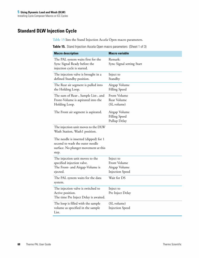
5 Using Dynamic Load and Wash (DLW)Installing Cycle Composer Macros or ICC Cycles
Standard DLW Injection Cycle
Table 15 lists the Stand Injection Accela Open macro parameters.
Table 15. Stand Injection Accela Open macro parameters (Sheet 1 of 3)
Macro description Macro variable
The PAL system waits first for the Sync Signal Ready before the injection cycle is started.
Remark:Sync Signal setting Start
The injection valve is brought in a defined Standby position.
Inject to Standby
The Rear air segment is pulled into the Holding Loop.
Airgap Volume Filling Speed
The sum of Rear-, Sample List-, and Front-Volume is aspirated into the Holding Loop.
The Front air segment is aspirated.
Front VolumeRear Volume(SL.volume)
Airgap VolumeFilling SpeedPullup Delay
The injection unit moves to the DLW Wash Station, Wash1 position.
The needle is inserted (dipped) for 1 second to wash the outer needle surface. No plunger movement at this step.
The injection unit moves to the specified injection valve.The Front- and Airgap-Volume is ejected.
Inject toFront VolumeAirgap VolumeInjection Speed
The PAL system waits for the data system.
Wait for DS
The injection valve is switched to Active position.The time Pre Inject Delay is awaited.
Inject toPre Inject Delay
The loop is filled with the sample volume as specified in the sample List.
(SL.volume)Injection Speed
68 Thermo PAL User Guide Thermo Scientific

5 Using Dynamic Load and Wash (DLW)Installing Cycle Composer Macros or ICC Cycles
The injection valve is switched to Standby position, the loop content is injected.Timer 1 Delay Stator Wash is started and a Start signal to the HPLC system is sent.
Post Inject Delay
Timer 1
The plunger of the DLW Syringe is pushed down to dispense the Rear Sample and Air Segment to Waste. The Holding Loop is still filled with Wash Solvent 1.
(Syr. Eject Speed)
The DLW Actuator/Solenoid is activated to deliver Wash Solvent 2 into the Holding Loop to clean the injection valve from Port 1 to Port 2.
For this step the needle tip is lifted, releasing the sealing pressure to enable rinsing around the tip sealing point.
Wash2Inject toNeedle Gap Valve CleanValve Clean Time Solvent 2
Remark: For a detailed explanation of the Needle Gap Valve Clean, see DLW Priming.
The injection unit is moved to the DLW Wash Station, Wash2 position.
The needle is rinsed inside and out with Wash Solvent 2.
Wash2(Syr.Eject Speed)
Post Clean Time Solvent2
The injection unit is moved back to the injection valve. The Inlet Port and engraving to waste Port are flushed with Wash Solvent 1 to prepare the valve for the next injection.
Wash1Inject toNeedle Gap Valve CleanValve Clean Time Solvent 1
The injection unit is moved back to the DLW Wash Station, Wash1 position to flush the syringe needle inside and out with Wash Solvent 1.
This is a preparation step for next injection, and especially important for biofluid samples.
Wash1Post Clean Time Solvent 1
Cycle end for LC-Inj DLW Standard macro.
Table 15. Stand Injection Accela Open macro parameters (Sheet 2 of 3)
Macro description Macro variable
Thermo Scientific Thermo PAL User Guide 69
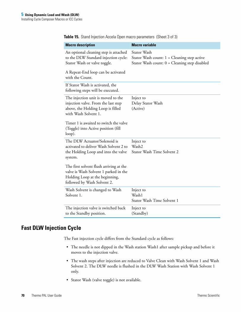
5 Using Dynamic Load and Wash (DLW)Installing Cycle Composer Macros or ICC Cycles
Fast DLW Injection Cycle
The Fast injection cycle differs from the Standard cycle as follows:
• The needle is not dipped in the Wash station Wash1 after sample pickup and before it moves to the injection valve.
• The wash steps after injection are reduced to Valve Clean with Wash Solvent 1 and Wash Solvent 2. The DLW needle is flushed in the DLW Wash Station with Wash Solvent 1 only.
• Stator Wash (valve toggle) is not available.
An optional cleaning step is attached to the DLW Standard injection cycle: Stator Wash or valve toggle.
A Repeat-End loop can be activated with the Count.
Stator WashStator Wash count: 1 = Cleaning step activeStator Wash count: 0 = Cleaning step disabled
If Stator Wash is activated, the following steps will be executed.
The injection unit is moved to the injection valve. From the last step above, the Holding Loop is filled with Wash Solvent 1.
Timer 1 is awaited to switch the valve (Toggle) into Active position (fill loop).
Inject toDelay Stator Wash(Active)
The DLW Actuator/Solenoid is activated to deliver Wash Solvent 2 to the Holding Loop and into the valve system.
The first solvent flush arriving at the valve is Wash Solvent 1 parked in the Holding Loop at the beginning, followed by Wash Solvent 2.
Inject toWash2Stator Wash Time Solvent 2
Wash Solvent is changed to Wash Solvent 1.
Inject toWash1Stator Wash Time Solvent 1
The injection valve is switched back to the Standby position.
Inject to(Standby)
Table 15. Stand Injection Accela Open macro parameters (Sheet 3 of 3)
Macro description Macro variable
70 Thermo PAL User Guide Thermo Scientific
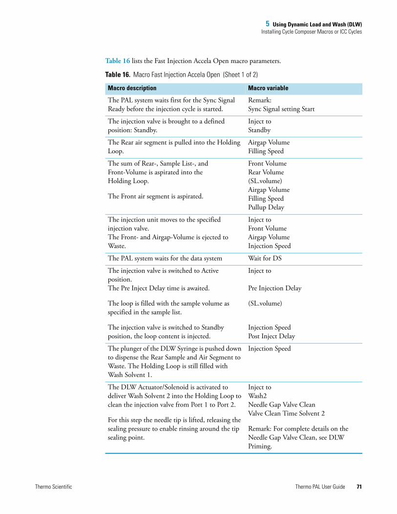
5 Using Dynamic Load and Wash (DLW)Installing Cycle Composer Macros or ICC Cycles
Table 16 lists the Fast Injection Accela Open macro parameters.
Table 16. Macro Fast Injection Accela Open (Sheet 1 of 2)
Macro description Macro variable
The PAL system waits first for the Sync Signal Ready before the injection cycle is started.
Remark:Sync Signal setting Start
The injection valve is brought to a defined position: Standby.
Inject toStandby
The Rear air segment is pulled into the Holding Loop.
Airgap VolumeFilling Speed
The sum of Rear-, Sample List-, and Front-Volume is aspirated into the Holding Loop.
The Front air segment is aspirated.
Front VolumeRear Volume(SL.volume)Airgap VolumeFilling SpeedPullup Delay
The injection unit moves to the specified injection valve.The Front- and Airgap-Volume is ejected to Waste.
Inject toFront VolumeAirgap VolumeInjection Speed
The PAL system waits for the data system Wait for DS
The injection valve is switched to Active position.The Pre Inject Delay time is awaited.
The loop is filled with the sample volume as specified in the sample list.
The injection valve is switched to Standby position, the loop content is injected.
Inject to
Pre Injection Delay
(SL.volume)
Injection SpeedPost Inject Delay
The plunger of the DLW Syringe is pushed down to dispense the Rear Sample and Air Segment to Waste. The Holding Loop is still filled with Wash Solvent 1.
Injection Speed
The DLW Actuator/Solenoid is activated to deliver Wash Solvent 2 into the Holding Loop to clean the injection valve from Port 1 to Port 2.
For this step the needle tip is lifted, releasing the sealing pressure to enable rinsing around the tip sealing point.
Inject toWash2Needle Gap Valve CleanValve Clean Time Solvent 2
Remark: For complete details on the Needle Gap Valve Clean, see DLW Priming.
Thermo Scientific Thermo PAL User Guide 71
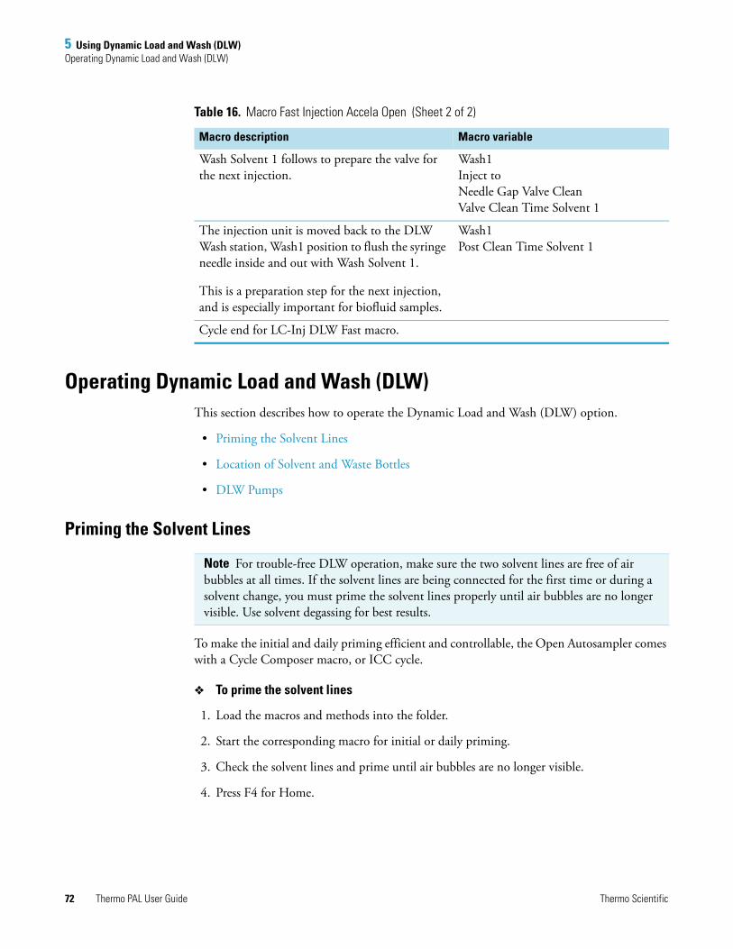
5 Using Dynamic Load and Wash (DLW)Operating Dynamic Load and Wash (DLW)
Operating Dynamic Load and Wash (DLW) This section describes how to operate the Dynamic Load and Wash (DLW) option.
• Priming the Solvent Lines
• Location of Solvent and Waste Bottles
• DLW Pumps
Priming the Solvent Lines
To make the initial and daily priming efficient and controllable, the Open Autosampler comes with a Cycle Composer macro, or ICC cycle.
To prime the solvent lines
1. Load the macros and methods into the folder.
2. Start the corresponding macro for initial or daily priming.
3. Check the solvent lines and prime until air bubbles are no longer visible.
4. Press F4 for Home.
Wash Solvent 1 follows to prepare the valve for the next injection.
Wash1Inject toNeedle Gap Valve CleanValve Clean Time Solvent 1
The injection unit is moved back to the DLW Wash station, Wash1 position to flush the syringe needle inside and out with Wash Solvent 1.
This is a preparation step for the next injection, and is especially important for biofluid samples.
Wash1Post Clean Time Solvent 1
Cycle end for LC-Inj DLW Fast macro.
Table 16. Macro Fast Injection Accela Open (Sheet 2 of 2)
Macro description Macro variable
Note For trouble-free DLW operation, make sure the two solvent lines are free of air bubbles at all times. If the solvent lines are being connected for the first time or during a solvent change, you must prime the solvent lines properly until air bubbles are no longer visible. Use solvent degassing for best results.
72 Thermo PAL User Guide Thermo Scientific
5 Using Dynamic Load and Wash (DLW)Operating Dynamic Load and Wash (DLW)
Location of Solvent and Waste Bottles
The DLW option contains self-priming membrane pumps. You can place the solvent bottles either in the fast wash station holder or on the lab bench.
You must place the Waste bottle greater than 30 cm (11.8 in.) below the injection valve. Make sure that the waste liquid can flow into the waste bottle without restriction. Place the waste tubing above the level of the liquid. Ideally, the tube is fixed at the neck of the waste bottle.
DLW Pumps
From the control point of view, the DLW pumps respond in the same manner as the fast wash station. Power-out signals activate the pumps. Because the electric current setting for the DLW is different, you must load the corresponding PAL Firmware Objects for the DLW wash station type.
The wetted parts in the pump are made from the following materials:
• Membrane: Kalrez (FFPM)
• Body, valves: Ryton PPS
The pumps are self priming with a suction lift of up to 3 m water column.
DLW Actuator/Solenoid
The DLW Actuator/Solenoid has the function of separating and completely shutting off the lines in the direction of the syringe (sample loading) or the wash solvent lines.
After opening the DLW Actuator/Solenoid for the wash solvent lines, you can pump the desired wash solvent into the system by activating the corresponding DLW pump.
Figure 66 on page 105 illustrates this functionality.
The wetted parts in the DLW Actuator Solenoid are made from the following materials:
• Solenoid body: PEEK™
• Seal material: FFKM (Simriz™)
Note Use good laboratory practice to avoid contaminating the wash solvents and the wash bottles. Avoid biological growth in pure water by either replacing it regularly or adding a small percentage of organic solvents, such as methanol or acetonitrile. Certain buffer solutions can decompose at room temperature when exposed to light. Filtering the wash solvents before filling the bottle, especially if using salt buffers, is mandatory to avoid any clogging of the solvent paths.
Thermo Scientific Thermo PAL User Guide 73
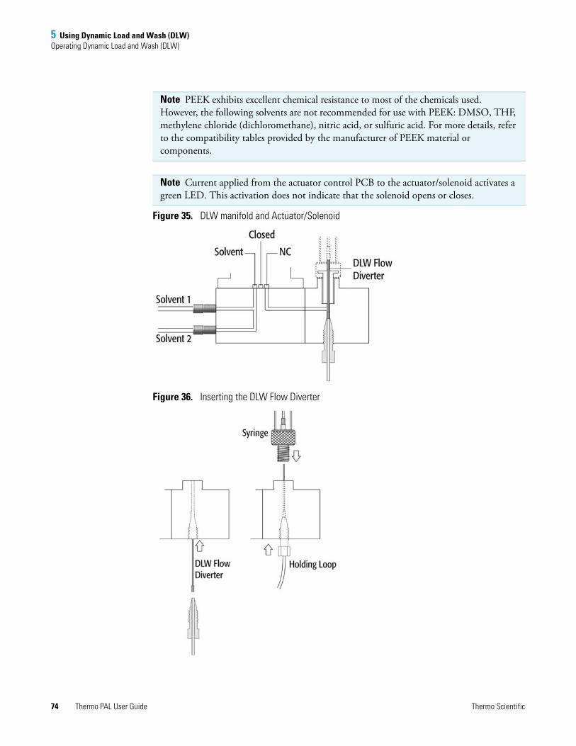
5 Using Dynamic Load and Wash (DLW)Operating Dynamic Load and Wash (DLW)
Figure 35. DLW manifold and Actuator/Solenoid
Figure 36. Inserting the DLW Flow Diverter
Note PEEK exhibits excellent chemical resistance to most of the chemicals used. However, the following solvents are not recommended for use with PEEK: DMSO, THF, methylene chloride (dichloromethane), nitric acid, or sulfuric acid. For more details, refer to the compatibility tables provided by the manufacturer of PEEK material or components.
Note Current applied from the actuator control PCB to the actuator/solenoid activates a green LED. This activation does not indicate that the solenoid opens or closes.
74 Thermo PAL User Guide Thermo Scientific

5 Using Dynamic Load and Wash (DLW)DLW Cycle Step-by-Step
DLW Cycle Step-by-StepThis section provides illustrations to demonstrate a step-by-step DLW cycle.
• Cycle for Standard Injection
• Additional Valve Toggle Step to DLW Standard Cycle
• Cycle for Fast Injection
Cycle for Standard Injection
Figure 37 to Figure 50 illustrate a step-by-step cycle for the standard injection.
Figure 37. Standard: Cycle start
Thermo Scientific Thermo PAL User Guide 75

5 Using Dynamic Load and Wash (DLW)DLW Cycle Step-by-Step
Figure 38. Standard: Step 1 – Aspirate rear air segment
76 Thermo PAL User Guide Thermo Scientific

5 Using Dynamic Load and Wash (DLW)DLW Cycle Step-by-Step
Figure 39. Standard: Step 2 – Get sample, aspirate rear, inject, and front volume
Thermo Scientific Thermo PAL User Guide 77
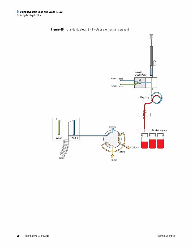
5 Using Dynamic Load and Wash (DLW)DLW Cycle Step-by-Step
Figure 40. Standard: Steps 3 - 4 – Aspirate front air segment
78 Thermo PAL User Guide Thermo Scientific
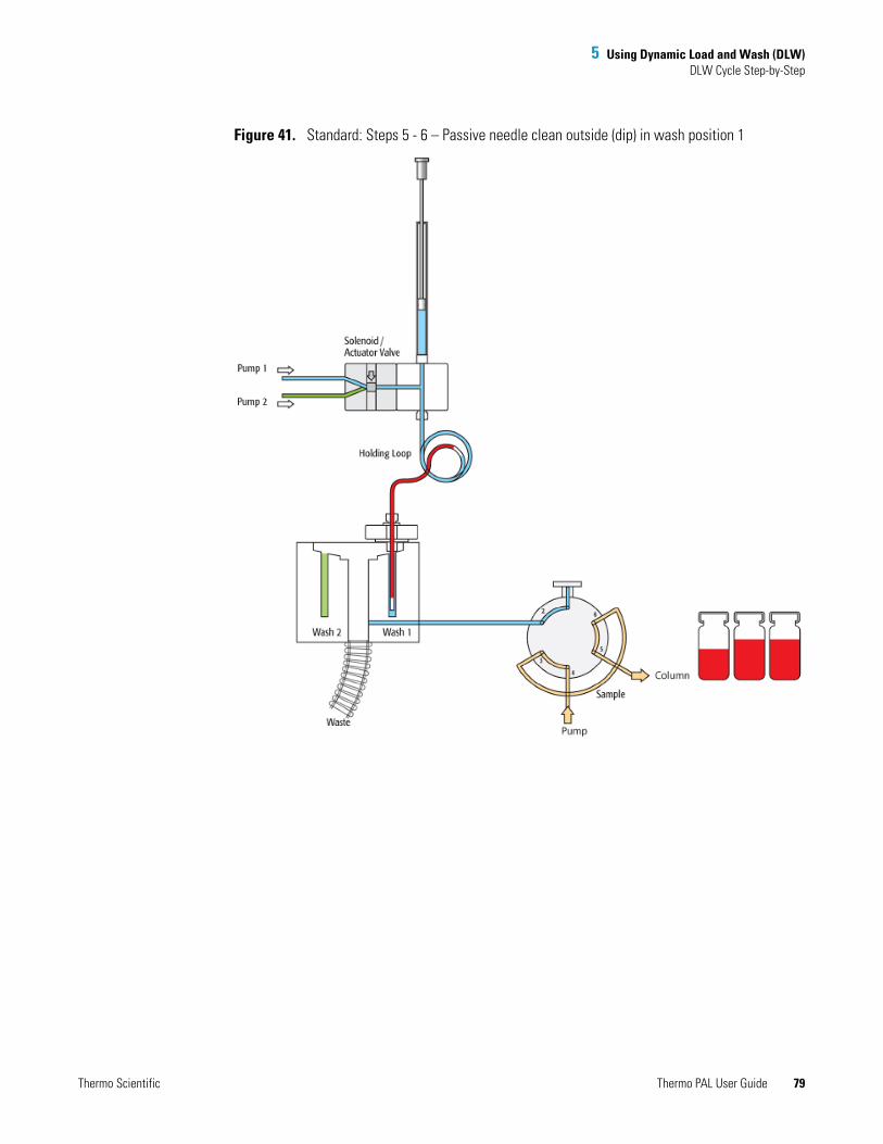
5 Using Dynamic Load and Wash (DLW)DLW Cycle Step-by-Step
Figure 41. Standard: Steps 5 - 6 – Passive needle clean outside (dip) in wash position 1
Thermo Scientific Thermo PAL User Guide 79

5 Using Dynamic Load and Wash (DLW)DLW Cycle Step-by-Step
Figure 42. Standard: Steps 7 - 8 – Dispense front air segment and front sample volume to waste
80 Thermo PAL User Guide Thermo Scientific
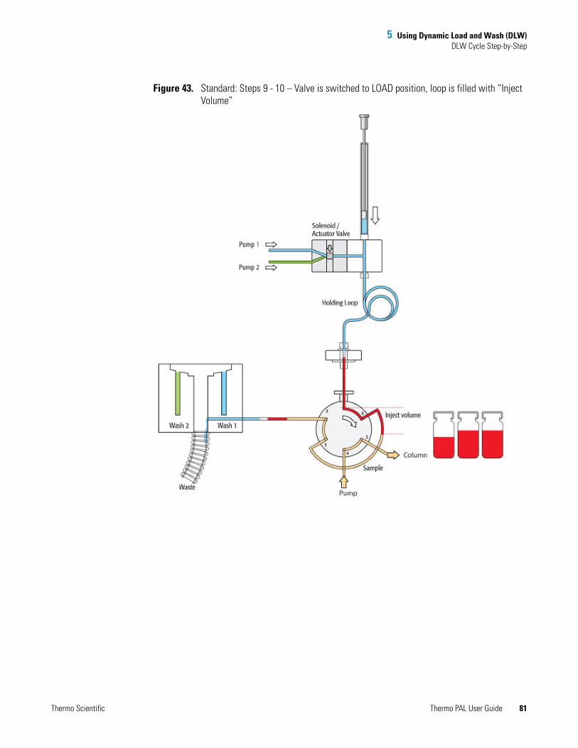
5 Using Dynamic Load and Wash (DLW)DLW Cycle Step-by-Step
Figure 43. Standard: Steps 9 - 10 – Valve is switched to LOAD position, loop is filled with “Inject Volume”
Thermo Scientific Thermo PAL User Guide 81

5 Using Dynamic Load and Wash (DLW)DLW Cycle Step-by-Step
Figure 44. Standard: Step 11– Valve is switched to INJECT position, start chromatographic process
82 Thermo PAL User Guide Thermo Scientific
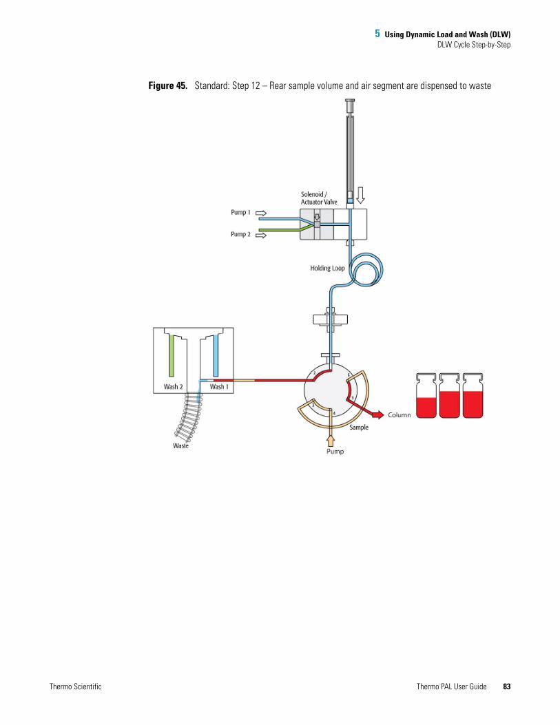
5 Using Dynamic Load and Wash (DLW)DLW Cycle Step-by-Step
Figure 45. Standard: Step 12 – Rear sample volume and air segment are dispensed to waste
Thermo Scientific Thermo PAL User Guide 83

5 Using Dynamic Load and Wash (DLW)DLW Cycle Step-by-Step
Figure 46. Standard: Steps 13 - 14 – Valve clean with Wash Solvent 2
84 Thermo PAL User Guide Thermo Scientific

5 Using Dynamic Load and Wash (DLW)DLW Cycle Step-by-Step
Figure 47. Standard: Steps 15 - 16 – Active syringe needle wash with Wash Solvent 2
Thermo Scientific Thermo PAL User Guide 85
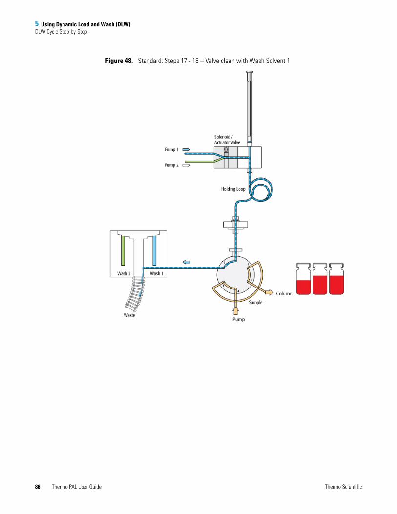
5 Using Dynamic Load and Wash (DLW)DLW Cycle Step-by-Step
Figure 48. Standard: Steps 17 - 18 – Valve clean with Wash Solvent 1
86 Thermo PAL User Guide Thermo Scientific
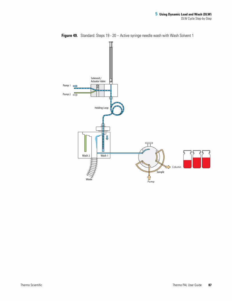
5 Using Dynamic Load and Wash (DLW)DLW Cycle Step-by-Step
Figure 49. Standard: Steps 19 - 20 – Active syringe needle wash with Wash Solvent 1
Thermo Scientific Thermo PAL User Guide 87

5 Using Dynamic Load and Wash (DLW)DLW Cycle Step-by-Step
Figure 50. Standard: Cycle end
Additional Valve Toggle Step to DLW Standard Cycle
This section contains information about additional steps that are necessary for a DLW Standard Cycle.
88 Thermo PAL User Guide Thermo Scientific
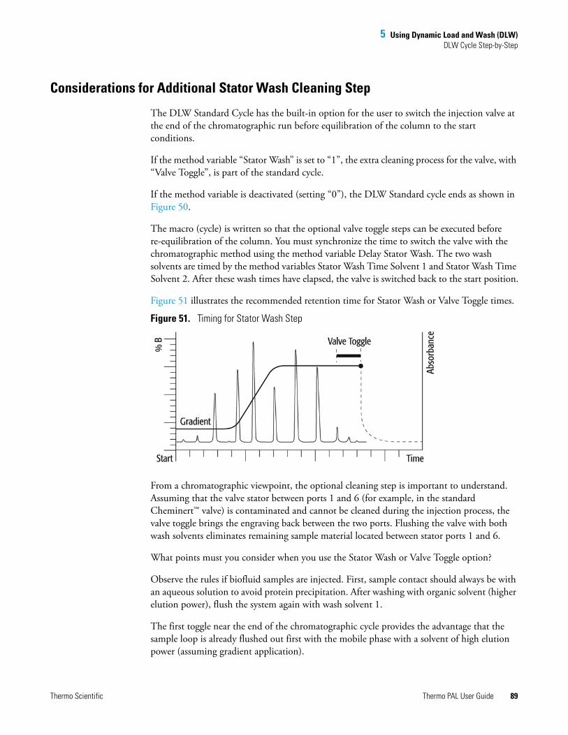
5 Using Dynamic Load and Wash (DLW)DLW Cycle Step-by-Step
Considerations for Additional Stator Wash Cleaning Step
The DLW Standard Cycle has the built-in option for the user to switch the injection valve at the end of the chromatographic run before equilibration of the column to the start conditions.
If the method variable “Stator Wash” is set to “1”, the extra cleaning process for the valve, with “Valve Toggle”, is part of the standard cycle.
If the method variable is deactivated (setting “0”), the DLW Standard cycle ends as shown in Figure 50.
The macro (cycle) is written so that the optional valve toggle steps can be executed before re-equilibration of the column. You must synchronize the time to switch the valve with the chromatographic method using the method variable Delay Stator Wash. The two wash solvents are timed by the method variables Stator Wash Time Solvent 1 and Stator Wash Time Solvent 2. After these wash times have elapsed, the valve is switched back to the start position.
Figure 51 illustrates the recommended retention time for Stator Wash or Valve Toggle times.
Figure 51. Timing for Stator Wash Step
From a chromatographic viewpoint, the optional cleaning step is important to understand. Assuming that the valve stator between ports 1 and 6 (for example, in the standard Cheminert™ valve) is contaminated and cannot be cleaned during the injection process, the valve toggle brings the engraving back between the two ports. Flushing the valve with both wash solvents eliminates remaining sample material located between stator ports 1 and 6.
What points must you consider when you use the Stator Wash or Valve Toggle option?
Observe the rules if biofluid samples are injected. First, sample contact should always be with an aqueous solution to avoid protein precipitation. After washing with organic solvent (higher elution power), flush the system again with wash solvent 1.
The first toggle near the end of the chromatographic cycle provides the advantage that the sample loop is already flushed out first with the mobile phase with a solvent of high elution power (assuming gradient application).
Thermo Scientific Thermo PAL User Guide 89

5 Using Dynamic Load and Wash (DLW)DLW Cycle Step-by-Step
The second valve toggle time follows immediately after finishing the second solvent flush. You cannot program a second switching time. The waiting time for the second valve toggle should be long enough so that the entire system is flushed out by both wash solvents.
Consider the entire delay volume to determine the second valve switch. The DLW internal volumes are as follows:
Manifold, 90 μL Holding Loop,108 μL Syringe Needle Gauge 22, 6.7 μL Installed Injection Loop
Total delay volume: 205 μL + Loop content volume
Do the second valve toggle (back to starting condition) before the system equilibration time has started. The Loop content is ideally a solvent of a low elution power when switched back.
If you apply isocratic chromatography, the remaining contaminants might be washed into the system and can build up higher background noise for the column, the detector, or both over a longer period of time.
90 Thermo PAL User Guide Thermo Scientific

5 Using Dynamic Load and Wash (DLW)DLW Cycle Step-by-Step
Additional Cleaning Step Stator Wash or Valve Toggle Step-by-Step
Figure 52 to Figure 57 illustrate additional cleaning steps for “Stator Wash.”
Stator Wash: End of Standard Injection CycleFigure 52. Start for additional cleaning step “Valve Toggle”
Thermo Scientific Thermo PAL User Guide 91
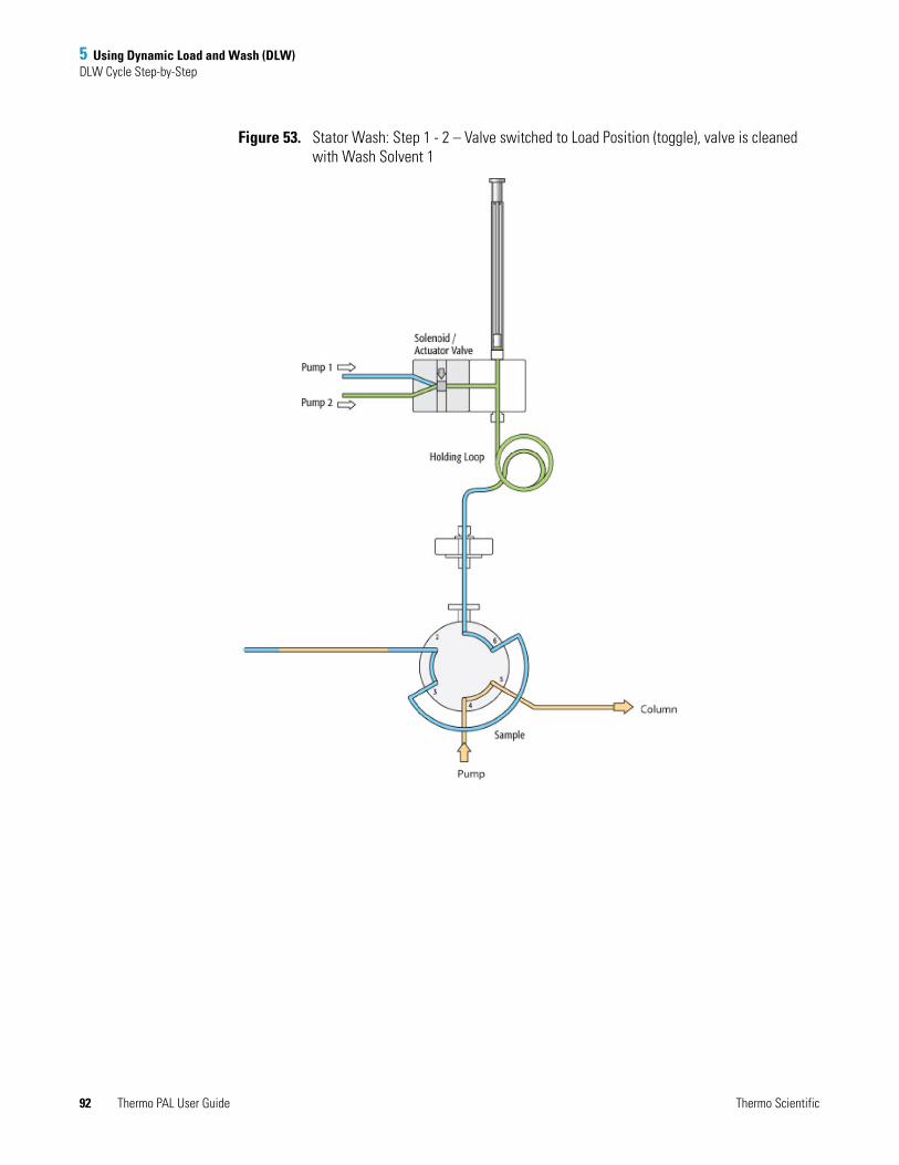
5 Using Dynamic Load and Wash (DLW)DLW Cycle Step-by-Step
Figure 53. Stator Wash: Step 1 - 2 – Valve switched to Load Position (toggle), valve is cleaned with Wash Solvent 1
92 Thermo PAL User Guide Thermo Scientific
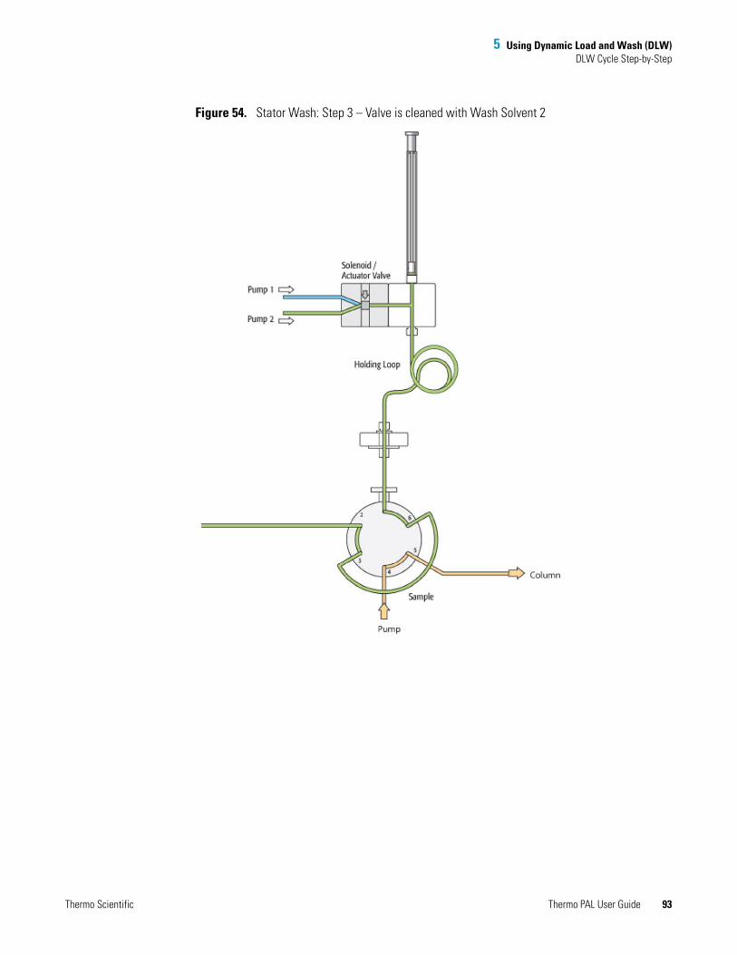
5 Using Dynamic Load and Wash (DLW)DLW Cycle Step-by-Step
Figure 54. Stator Wash: Step 3 – Valve is cleaned with Wash Solvent 2
Thermo Scientific Thermo PAL User Guide 93
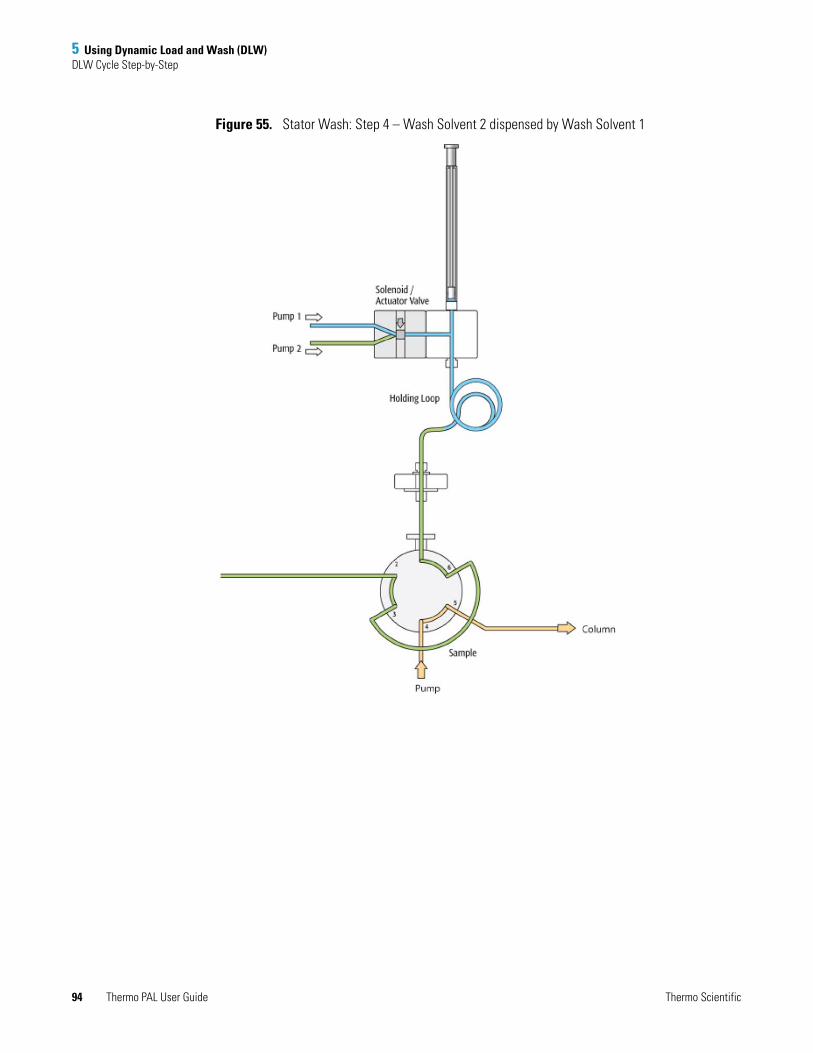
5 Using Dynamic Load and Wash (DLW)DLW Cycle Step-by-Step
Figure 55. Stator Wash: Step 4 – Wash Solvent 2 dispensed by Wash Solvent 1
94 Thermo PAL User Guide Thermo Scientific
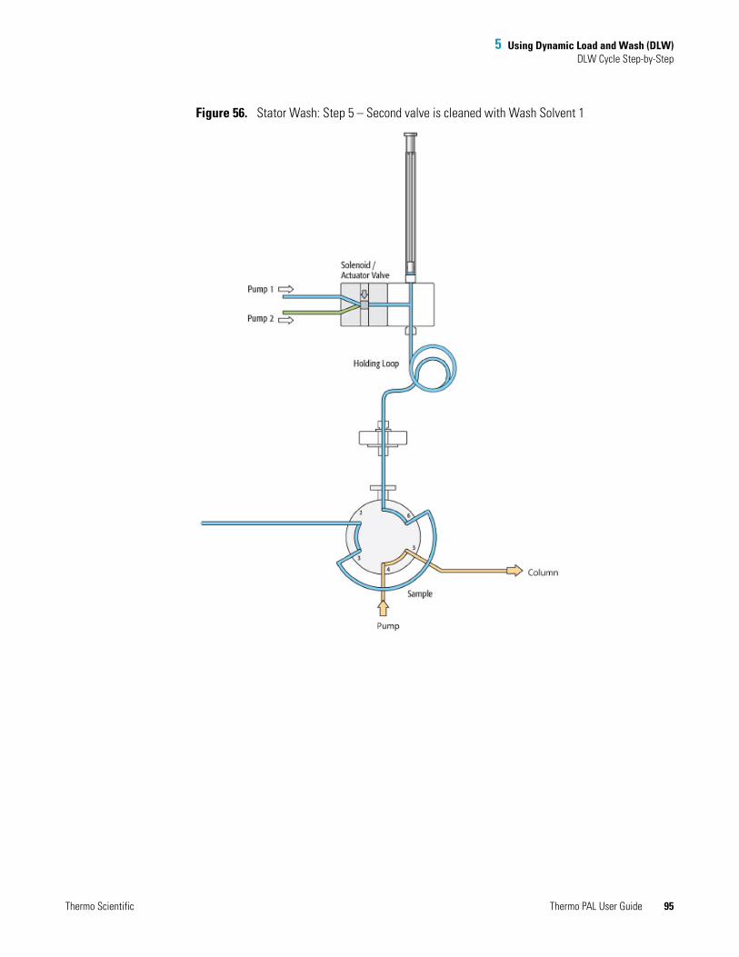
5 Using Dynamic Load and Wash (DLW)DLW Cycle Step-by-Step
Figure 56. Stator Wash: Step 5 – Second valve is cleaned with Wash Solvent 1
Thermo Scientific Thermo PAL User Guide 95

5 Using Dynamic Load and Wash (DLW)DLW Cycle Step-by-Step
Figure 57. Stator Wash: Step 6 – Valve switched back to Inject Position (toggle)
96 Thermo PAL User Guide Thermo Scientific

5 Using Dynamic Load and Wash (DLW)DLW Cycle Step-by-Step
Cycle for Fast Injection
Figure 58 to Figure 69 illustrate a step-by-step cycle for the Fast Injection.
Figure 58. Fast: Cycle start
Thermo Scientific Thermo PAL User Guide 97

5 Using Dynamic Load and Wash (DLW)DLW Cycle Step-by-Step
Figure 59. Fast: Step 1 – Aspirate rear air segment
98 Thermo PAL User Guide Thermo Scientific
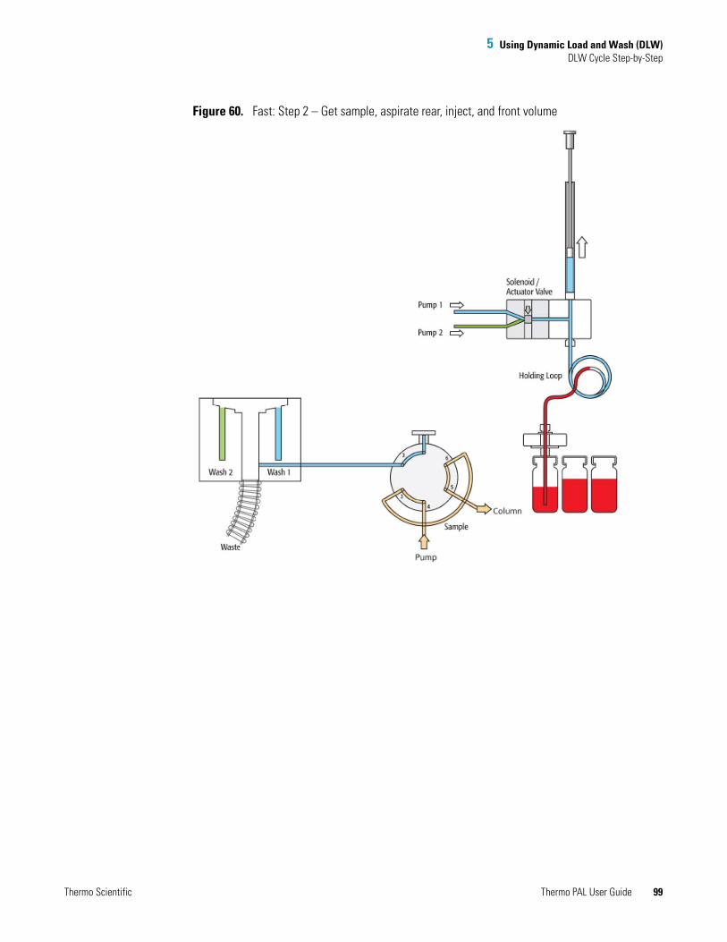
5 Using Dynamic Load and Wash (DLW)DLW Cycle Step-by-Step
Figure 60. Fast: Step 2 – Get sample, aspirate rear, inject, and front volume
Thermo Scientific Thermo PAL User Guide 99
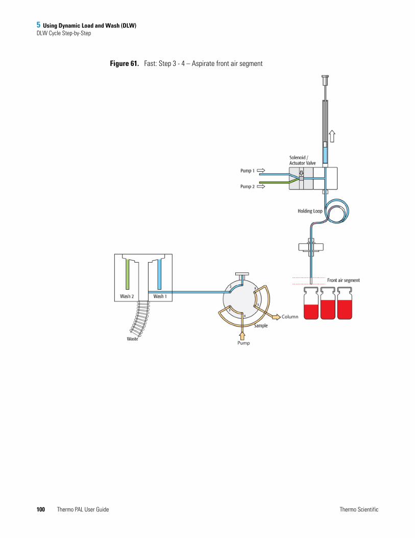
5 Using Dynamic Load and Wash (DLW)DLW Cycle Step-by-Step
Figure 61. Fast: Step 3 - 4 – Aspirate front air segment
100 Thermo PAL User Guide Thermo Scientific
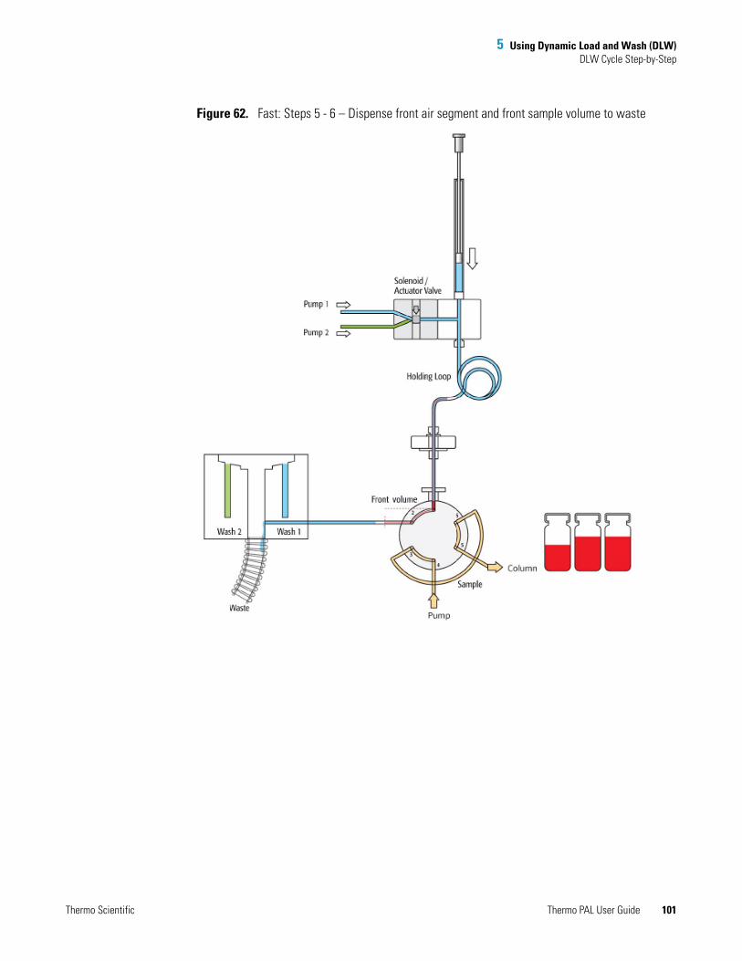
5 Using Dynamic Load and Wash (DLW)DLW Cycle Step-by-Step
Figure 62. Fast: Steps 5 - 6 – Dispense front air segment and front sample volume to waste
Thermo Scientific Thermo PAL User Guide 101

5 Using Dynamic Load and Wash (DLW)DLW Cycle Step-by-Step
Figure 63. Fast: Steps 7 - 8 – Valve is switched to LOAD position, loop is filled with “Inject Volume”
102 Thermo PAL User Guide Thermo Scientific

5 Using Dynamic Load and Wash (DLW)DLW Cycle Step-by-Step
Figure 64. Fast: Step 9 – Valve is switched to INJECT position, start chromatographic process
Thermo Scientific Thermo PAL User Guide 103

5 Using Dynamic Load and Wash (DLW)DLW Cycle Step-by-Step
Figure 65. Fast: Step 10 – Rear sample volume and air segment are dispensed to waste
104 Thermo PAL User Guide Thermo Scientific
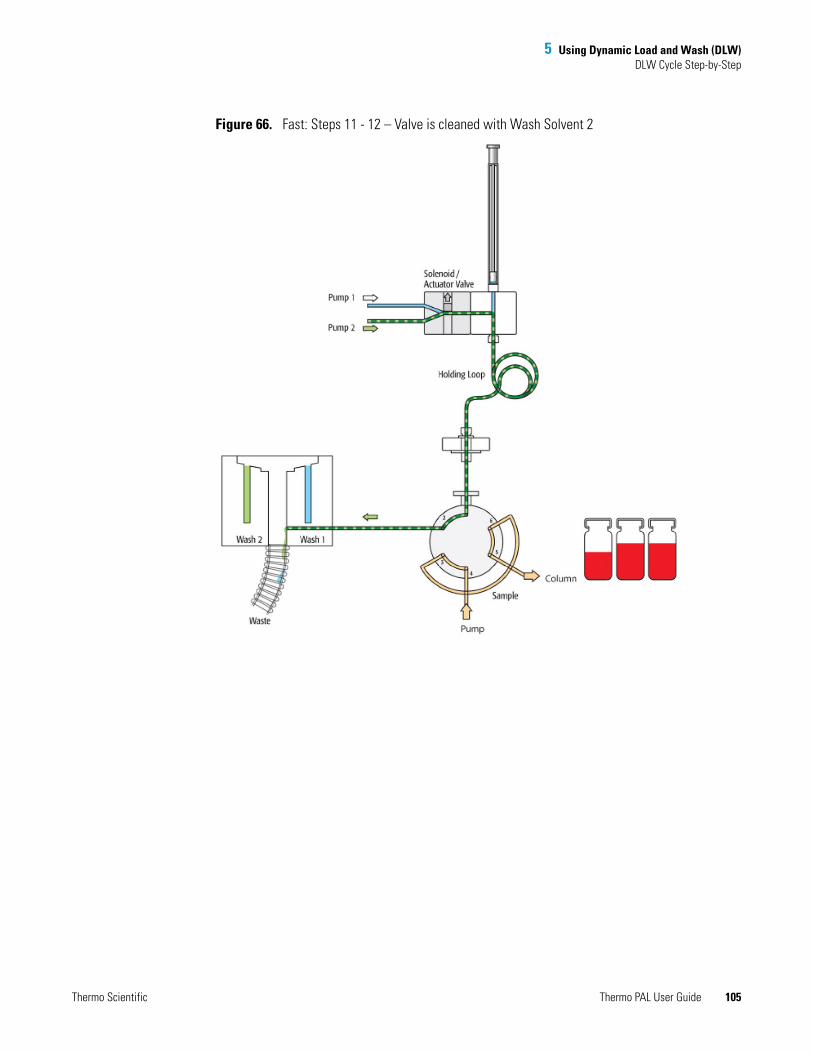
5 Using Dynamic Load and Wash (DLW)DLW Cycle Step-by-Step
Figure 66. Fast: Steps 11 - 12 – Valve is cleaned with Wash Solvent 2
Thermo Scientific Thermo PAL User Guide 105
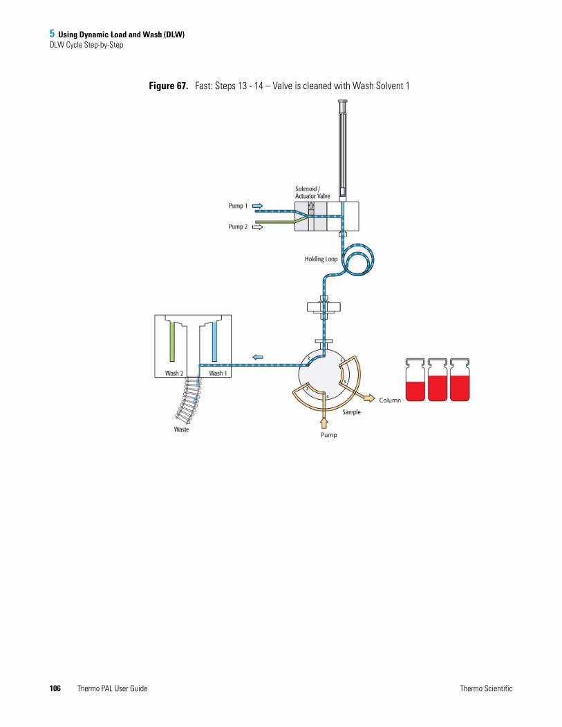
5 Using Dynamic Load and Wash (DLW)DLW Cycle Step-by-Step
Figure 67. Fast: Steps 13 - 14 – Valve is cleaned with Wash Solvent 1
106 Thermo PAL User Guide Thermo Scientific

5 Using Dynamic Load and Wash (DLW)DLW Cycle Step-by-Step
Figure 68. Fast: Step 15 – Active syringe needle wash with Wash Solvent 1
Thermo Scientific Thermo PAL User Guide 107
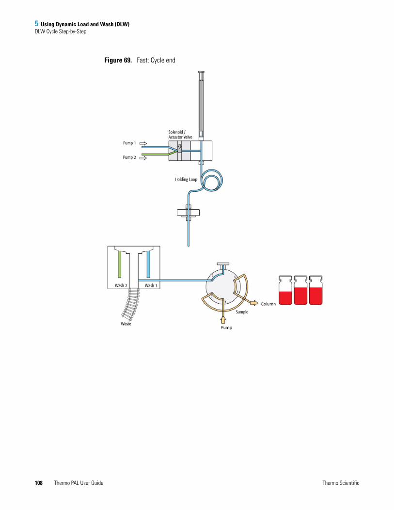
5 Using Dynamic Load and Wash (DLW)DLW Cycle Step-by-Step
Figure 69. Fast: Cycle end
108 Thermo PAL User Guide Thermo Scientific

I
Index
Aautosampler control terminal, using 20
Ccables
DB9 to DB9 serial cable 14external contact trigger cable 10PAL interface cable 10Thermo Dual Configuration cable 8Thermo Single Configuration cable 4
complianceFCC iiiregulatory iiiWEEE v
computer Com port 17contact closure connections
for a Thermo Scientific LC pump 5for a Thermo Scientific MS detector 5for an Agilent pump 10for two Thermo Scientific pumps 8
control terminal attached to the autosampler 20cycle composer macros 62cycle composer macros or ICC cycles, installing 62Cycle Editor 62
Ddelay time 28Direct Control Configuration page 57Direct Control dialog box, opening 51DLW
characterizing features 62cycle 73cycle for fast injection 95cycle for standard injection 73fast injection cycle 68macro definitions 63operating 70overview 61priming solvent lines 64
standard injection cycle 66DLW Actuator/Solenoid 71DLW Pumps 71
Eelectromagnetic compatibility iiiexternal contact board for Agilent pump 10external contact closure cable connections 5
FFCC compliance iiifile types
instrument methods (*.meth) 29macro (*.pma) 45templates (*.pme) 35
IICC cycles 62Injected screen on hand-held controller 23Inlet Direct Control, opening 52Instrument Configuration window 15Instrument Setup window, opening 24
JJob Queue screen 21
Llevel surface, importance of 2lithium battery 1look ahead injections 17
MMacro Editor
enabling 18opening 43
macros
Thermo Scientific Thermo PAL User Guide 107
Index: N
creating 43importing 18list of standard 42
Menu screen 21method parameters, specifying 24
Nnumeric variables 49
Oobject variables 49ordering information 2output signal to LC pump 3
Ppart numbers 2priming solvent lines 64pulse time of the out signals, setting 23pumps, self-priming 62
RRecommended Injection Volume box 28regulatory compliance iii
Ssafety information 1safety standards iiiself-priming micro pumps 62solvent lines, priming 64solvent lnes, priming 70syringe size, specifying 28
TTemplate Editor
enabling 18opening 33
templatesediting 33Single Step LC Injection 26testing 37
Thermo PAL driver for Xcalibur 62Tray Configuration page 56tray type, selecting with the PAL Control Terminal 21Trays screen 21Tune window, making single injections from 53
Vvariables, defining 48
WWaiting for contact closure status for LC pump 22WEEE compliance v
108 Thermo PAL User Guide Thermo Scientific


