62
Thermo Scientific Solaris 2000 / 4000 Instruction Manual 70900190-b • 04 / 2019

Thermo Scientific Solaris 2000 / 4000
Instruction Manual70900190-b • 04 / 2019
ContentsPreface � � � � � � � � � � � � � � � � � � � � � � � � � � � � � � � � � � � � � � � � � 6
Intended Use � � � � � � � � � � � � � � � � � � � � � � � � � � � � � � � � � � � � � � � 6
Signal Words and Symbols � � � � � � � � � � � � � � � � � � � � � � � � � � � 6Symbols used on Shaker and Accessories � � � � � � � � � � � 6Symbols used in the Instruction Manual � � � � � � � � � � � � � 7
Safety Instructions � � � � � � � � � � � � � � � � � � � � � � � � � � � � � � � � � � 7
1� Technical Specifications � � � � � � � � � � � � � � � � � � � � � � � � 111� 1� Technical Data � � � � � � � � � � � � � � � � � � � � � � � � � � � � � � � 11
Thermo Scientific Solaris 2000 Shaker � � � � � � � � � � � � � 11Thermo Scientific Solaris 4000 Shaker � � � � � � � � � � � � � 12
1� 2� Accessories � � � � � � � � � � � � � � � � � � � � � � � � � � � � � � � � � � 131� 2� 1� Platforms � � � � � � � � � � � � � � � � � � � � � � � � � � � � � � � � � � � � � 131� 2� 2� Clamps � � � � � � � � � � � � � � � � � � � � � � � � � � � � � � � � � � � � � � 141� 2� 3� Test Tube Racks � � � � � � � � � � � � � � � � � � � � � � � � � � � � � � � 16
1� 3� Directives and Standards � � � � � � � � � � � � � � � � � � � � � � 18
1� 4� Product Overview � � � � � � � � � � � � � � � � � � � � � � � � � � � � � 191� 4� 1� Solaris 2000 � � � � � � � � � � � � � � � � � � � � � � � � � � � � � � � � � � 191� 4� 2� Solaris 4000 � � � � � � � � � � � � � � � � � � � � � � � � � � � � � � � � � � 191� 4� 3� Connections � � � � � � � � � � � � � � � � � � � � � � � � � � � � � � � � � � 20
2� Transport and Set Up � � � � � � � � � � � � � � � � � � � � � � � � � � 212� 1� Unpacking � � � � � � � � � � � � � � � � � � � � � � � � � � � � � � � � � � � 21
Items Supplied � � � � � � � � � � � � � � � � � � � � � � � � � � � � � � � � 21
2� 2� Location � � � � � � � � � � � � � � � � � � � � � � � � � � � � � � � � � � � � � 22
2� 3� Transporting � � � � � � � � � � � � � � � � � � � � � � � � � � � � � � � � � 23
2� 4� Leveling � � � � � � � � � � � � � � � � � � � � � � � � � � � � � � � � � � � � � 23
2� 5� Mains Connection � � � � � � � � � � � � � � � � � � � � � � � � � � � � 24
2� 6� Initial Startup � � � � � � � � � � � � � � � � � � � � � � � � � � � � � � � � � 24
2� 7� Storage � � � � � � � � � � � � � � � � � � � � � � � � � � � � � � � � � � � � � 27
2� 8� Shipping � � � � � � � � � � � � � � � � � � � � � � � � � � � � � � � � � � � � � 27

3� Operation � � � � � � � � � � � � � � � � � � � � � � � � � � � � � � � � � � � � 283� 1� Power on / off � � � � � � � � � � � � � � � � � � � � � � � � � � � � � � � � 28
3� 2� Graphical User Interface � � � � � � � � � � � � � � � � � � � � � � � 283� 2� 1� Status � � � � � � � � � � � � � � � � � � � � � � � � � � � � � � � � � � � � � � � 283� 2� 2� Settings � � � � � � � � � � � � � � � � � � � � � � � � � � � � � � � � � � � � � � 303� 2� 3� Programs � � � � � � � � � � � � � � � � � � � � � � � � � � � � � � � � � � � � � 33
3� 3� Accessories � � � � � � � � � � � � � � � � � � � � � � � � � � � � � � � � � � 413� 3� 1� Platform Installation � � � � � � � � � � � � � � � � � � � � � � � � � � � � 413� 3� 2� Clamp and Vessel Installation � � � � � � � � � � � � � � � � � � � � 443� 3� 3� Test Tube Rack Clamp Installation � � � � � � � � � � � � � � � � � 463� 3� 4� Microplate / Deepwell-Plate Installation � � � � � � � � � � � � � 47
3� 4� Loading and Normal Use � � � � � � � � � � � � � � � � � � � � � � � 48Loading � � � � � � � � � � � � � � � � � � � � � � � � � � � � � � � � � � � � � � 48Normal Use � � � � � � � � � � � � � � � � � � � � � � � � � � � � � � � � � � � 49
4� Maintenance and Care � � � � � � � � � � � � � � � � � � � � � � � � � 524� 1� Basics � � � � � � � � � � � � � � � � � � � � � � � � � � � � � � � � � � � � � � 53
Inspection of Accessories � � � � � � � � � � � � � � � � � � � � � � � 53
4� 2� Cleaning � � � � � � � � � � � � � � � � � � � � � � � � � � � � � � � � � � � � 54Touchscreen � � � � � � � � � � � � � � � � � � � � � � � � � � � � � � � � � � 54
4� 3� Disinfection � � � � � � � � � � � � � � � � � � � � � � � � � � � � � � � � � � 55
4� 4� Decontamination � � � � � � � � � � � � � � � � � � � � � � � � � � � � � 55
4� 5� Autoclaving � � � � � � � � � � � � � � � � � � � � � � � � � � � � � � � � � � 56
4� 6� Service � � � � � � � � � � � � � � � � � � � � � � � � � � � � � � � � � � � � � � 57
4� 7� Shipping and Disposal � � � � � � � � � � � � � � � � � � � � � � � � � 57
5� Troubleshooting� � � � � � � � � � � � � � � � � � � � � � � � � � � � � � � 58
List of FiguresFigure 1: Overview Solaris 2000 � � � � � � � � � � � � � � � � � � � � � � � � � � 19Figure 2: Overview Solaris 4000 � � � � � � � � � � � � � � � � � � � � � � � � � � 19Figure 3: Rear View (left: Solaris 4000, right: Solaris 2000) � � � � � 20Figure 4: Set up clearance of 8 cm (3 in) � � � � � � � � � � � � � � � � � � � 22Figure 5: How to carry a shaker � � � � � � � � � � � � � � � � � � � � � � � � � � 23Figure 6: Initial startup � � � � � � � � � � � � � � � � � � � � � � � � � � � � � � � � � 24Figure 7: Initial startup - language � � � � � � � � � � � � � � � � � � � � � � � � 25Figure 8: Initial startup - unit name � � � � � � � � � � � � � � � � � � � � � � � 25Figure 9: Initial startup - region � � � � � � � � � � � � � � � � � � � � � � � � � � 25Figure 10: Initial startup - set date display format � � � � � � � � � � � � 26Figure 11: Initial startup - set date � � � � � � � � � � � � � � � � � � � � � � � � 26Figure 12: Initial startup - set time � � � � � � � � � � � � � � � � � � � � � � � � 26Figure 13: Initial startup - installation instruction � � � � � � � � � � � � � 26Figure 14: Home Screen of the Graphical User Interface (GUI) � � 28Figure 15: Settings � � � � � � � � � � � � � � � � � � � � � � � � � � � � � � � � � � � � 30Figure 16: Speed setpoint � � � � � � � � � � � � � � � � � � � � � � � � � � � � � � 30Figure 17: Orbit calculator � � � � � � � � � � � � � � � � � � � � � � � � � � � � � � 31Figure 18: Orbit calculated � � � � � � � � � � � � � � � � � � � � � � � � � � � � � 31Figure 19: Calculate custom sized orbit � � � � � � � � � � � � � � � � � � � � 31Figure 20: Time Mode � � � � � � � � � � � � � � � � � � � � � � � � � � � � � � � � � � 32Figure 21: Menu Bar Customization � � � � � � � � � � � � � � � � � � � � � � � 33Figure 22: Files and Info � � � � � � � � � � � � � � � � � � � � � � � � � � � � � � � � 33Figure 23: Programs � � � � � � � � � � � � � � � � � � � � � � � � � � � � � � � � � � � 34Figure 24: Create program � � � � � � � � � � � � � � � � � � � � � � � � � � � � � � 34Figure 25: Add step � � � � � � � � � � � � � � � � � � � � � � � � � � � � � � � � � � � 35Figure 26: Delete program � � � � � � � � � � � � � � � � � � � � � � � � � � � � � � 35Figure 27: Program quick view � � � � � � � � � � � � � � � � � � � � � � � � � � � 36Figure 28: Program complete � � � � � � � � � � � � � � � � � � � � � � � � � � � � 36Figure 29: Select programs for import � � � � � � � � � � � � � � � � � � � � � 36Figure 30: Program import complete � � � � � � � � � � � � � � � � � � � � � � 37Figure 31: Select programs for export � � � � � � � � � � � � � � � � � � � � � 37Figure 32: Program export complete � � � � � � � � � � � � � � � � � � � � � � 37Figure 33: Event Log � � � � � � � � � � � � � � � � � � � � � � � � � � � � � � � � � � � 38Figure 34: Filter event log � � � � � � � � � � � � � � � � � � � � � � � � � � � � � � � 38
Figure 35: Select event log for export � � � � � � � � � � � � � � � � � � � � � 39Figure 36: Insert USB drive for export � � � � � � � � � � � � � � � � � � � � � 39Figure 37: Charts � � � � � � � � � � � � � � � � � � � � � � � � � � � � � � � � � � � � � 40Figure 38: Example of an universal platform � � � � � � � � � � � � � � � � 42Figure 39: Universal platform installed on a Solaris 2000 (left) and a Solaris 4000 (right) shaker � � � � � � � � � � � � � � � � � � � � � � � � � 42Figure 40: Dual Stack Platform Assembly � � � � � � � � � � � � � � � � � � 43Figure 41: Dual stack platform on a Solaris 4000 shaker � � � � � � 44Figure 42: Clamp details with 2 springs � � � � � � � � � � � � � � � � � � � � 45Figure 43: Test Tube Rack Clamp Assembly � � � � � � � � � � � � � � � � 46Figure 44: Microplate / Deepwell-plate assembly � � � � � � � � � � � � 47Figure 45: Example for a well loaded platform � � � � � � � � � � � � � � 48Figure 46: Example for a poorly loaded platform � � � � � � � � � � � � � 49Figure 47: Solaris 2000 – Normal Use � � � � � � � � � � � � � � � � � � � � � 50Figure 48: Solaris 4000 – Normal Use � � � � � � � � � � � � � � � � � � � � � 51
List of TablesTable 1: Technical Data Solaris 2000 � � � � � � � � � � � � � � � � � � � � � � � 11Table 2: Technical Data Solaris 4000 � � � � � � � � � � � � � � � � � � � � � � � 12Table 3: Available platforms � � � � � � � � � � � � � � � � � � � � � � � � � � � � � � 13Table 4: Available clamps for Solaris 2000 platforms � � � � � � � � � � 14Table 5: Available clamps for Solaris 4000 platforms � � � � � � � � � � 15Table 6: Available test tube racks for Solaris 2000 platforms � � � � 16Table 7: Available test tube racks for Solaris 4000 platforms � � � � 17Table 8: Directives and Standards � � � � � � � � � � � � � � � � � � � � � � � � � 18Table 9: Items Supplied � � � � � � � � � � � � � � � � � � � � � � � � � � � � � � � � � 21Table 10: Autoclavability of materials � � � � � � � � � � � � � � � � � � � � � � 56Table 11: Troubleshooting � � � � � � � � � � � � � � � � � � � � � � � � � � � � � � � 59

6 / 62
Preface
Intended Use
A device used in research and manufacturing to shake solutions in a 2D orbit while controlling speed and time in applications.
This shaker must be operated by trained personnel only.
Signal Words and Symbols
Signal Word Degree of Hazard
WARNING Indicates a hazardous situation that, if not avoided, could result in death or serious injury.
CAUTION Inidicates a hazardous situation that, if not avoided, could result in minor or moderate injury.
NOTICE Indicates information considered important, but not hazard-related.
Symbols used on Shaker and AccessoriesObserve the information contained in this instruction manual to keep yourself and your environment safe.
Refer to instruction manual
Disconnect mains plug
General hazard

7 / 62
Symbols used in the Instruction ManualObserve the information contained in the instruction manual to keep yourself and your environment safe.
General hazard Electrical hazard
Biological hazard Danger of cuts
Hazard caused by flammable materials
Indicates information considered important, but not hazard-related.
Safety Instructions
WARNING
Not following these safety instructions can lead to hazardous situations that, if not avoided, could result in death or serious injury. � Observe the safety instructions. � The shaker is to be used for its intended use only.
Improper use can cause damage, contamination, and injuries with fatal consequences.
� The shaker must be operated by trained personnel only. � It is the obligation of the operator to make sure, that
the proper personal protective equipment is used. Mind the “Laboratory Biosafety Manual” of the World Health Organization (WHO) and the regulations in your country.
WARNING
Damage from wrong power supply.Make sure that the shaker is plugged only into sockets which have been properly grounded.

8 / 62
WARNING
Risk from handling hazardous substances.When working with corrosive samples (salt solutions, acids, bases), the accessories and the shaker have to be cleaned thoroughly. � The shaker is neither inert nor protected against
explosion. Never use the shaker in an explosion-prone environment.
� Do not shake toxic or radioactive materials or any pathogenic micro-organisms without suitable safety precautions.
� If shaking any hazardous materials mind the “Laboratory Biosafety Manual” of the World Health Organization (WHO) and any local regulations. When shaking microbiological samples from the Risk Group II (according to the “Laboratory Biosafety Manual” of the World Health Organization (WHO)), aerosol-tight biological seals have to be used. Look on the internet page of the World Health Organization (www.who.int) for the “Laboratory Biosafety Manual”. For materials in a higher risk group, extra safety measures must be taken.
� If toxins or pathogenic substances have contaminated the shaker or its parts, appropriate disinfection measures have to be taken (“Decontamination” on page 55; „Disinfection“ on page 55).
� If a hazardous situation occurs, turn off the power supply to the shaker and leave the area immediately.
WARNING
Damage to health from infectious substances.If an accidental spill places liquids or other materials under the platform, immediately power off the shaker, unplug it, and remove the platform (“Platforms” on page 13).Clean up the spill following your regular laboratory procedures. Use proper personal protective equipment.
WARNING
Damage to health from shaking explosive or flammable materials or substances.Do not shake explosive or flammable materials or substances.
9 / 62
CAUTION
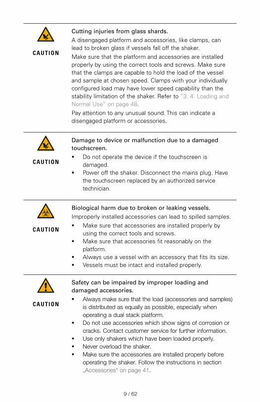
Cutting injuries from glass shards.A disengaged platform and accessories, like clamps, can lead to broken glass if vessels fall off the shaker.Make sure that the platform and accessories are installed properly by using the correct tools and screws. Make sure that the clamps are capable to hold the load of the vessel and sample at chosen speed. Clamps with your individually configured load may have lower speed capability than the stability limitation of the shaker. Refer to “3. 4. Loading and Normal Use” on page 48.Pay attention to any unusual sound. This can indicate a disengaged platform or accessories.
CAUTION
Damage to device or malfunction due to a damaged touchscreen. � Do not operate the device if the touchscreen is
damaged. � Power off the shaker. Disconnect the mains plug. Have
the touchscreen replaced by an authorized service technician.
CAUTION
Biological harm due to broken or leaking vessels.Improperly installed accessories can lead to spilled samples. � Make sure that accessories are installed properly by
using the correct tools and screws. � Make sure that accessories fit reasonably on the
platform. � Always use a vessel with an accessory that fits its size. � Vessels must be intact and installed properly.
CAUTION
Safety can be impaired by improper loading and damaged accessories. � Always make sure that the load (accessories and samples)
is distributed as equally as possible, especially when operating a dual stack platform.
� Do not use accessories which show signs of corrosion or cracks. Contact customer service for further information.
� Use only shakers which have been loaded properly. � Never overload the shaker. � Make sure the accessories are installed properly before
operating the shaker. Follow the instructions in section „Accessories“ on page 41.

10 / 62
CAUTION
Physical harm caused by ignoring operative basics. � Never operate the shaker without a properly installed
platform. � Never use the shaker if parts of its exterior are damaged
or missing. � Do not move the shaker while it is running. � Do not lean on the shaker. � Never load or unload the shaker until it has come to
a complete stop and this has been confirmed on the touchscreen.
� Do not put anything on the shaker while it is running. � Do not touch the platform or any accessories on the
shaker while it is running. � The shaker housing is not to be opened by the operator.
NOTICE
Protection may be impaired by incompatible accessories.Use only accessories for this shaker which have been approved by Thermo Fisher Scientific. For updated lists check www.thermofisher.com.
NOTICE
To shut down the shaker: Press the STOP key. Turn off the shaker at the main switch. Pull out the power supply plug. In an emergency disconnect the power supply.
11 / 62
1. Technical Specifications
1. 1. Technical Data
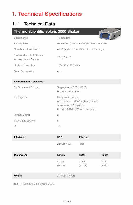
Thermo Scientific Solaris 2000 Shaker
Speed Range 15–525 rpm
Running Time 99 h 59 min (1 min increment) or continuous mode
Noise Level at max. Speed 62 dB (A) (1m in front of the unit at 1.6 m height)
Maximum Load (incl. Platform,
Accessories and Samples)25 kg (55 lbs)
Electrical Connection 100–240 V, 50 / 60 Hz
Power Consumption 60 W
Environmental Conditions
For Storage and Shipping Temperature: -10 °C to 55 °C
Humidity: 15% to 85%
For Operation Use in interior spaces
Altitudes of up to 3 000 m above sea level
Temperature: 5 °C to 40 °C
Humidity: 20% to 80%, non-condensing.
Pollution Degree 2
Overvoltage Category II
IP 20
Interfaces USB Ethernet
2x USB-A 2.0 RJ45
Dimensions Length Width Heigth
47 cm
(18.5 in)
37 cm
(14.5 in)
15 cm
(5.5 in)
Weight 20.9 kg (46,0 lbs)
Table 1: Technical Data Solaris 2000

12 / 62
Thermo Scientific Solaris 4000 Shaker
Speed Range 15–525 rpm
Running Time 99 h 59 min (1 min increment) or continuous mode
Noise Level at max. Speed 62 dB (A) (1 m in front of the unit at 1.6 m height)
Maximum Load (incl. Platform,
Accessories and Samples)43 kg (95 lbs)
Electrical Connection 100–240 V, 50 / 60 Hz
Power Consumption 80 W
Environmental Conditions
For Storage and Shipping Temperature: -10 °C to 55 °C
Humidity: 15% to 85%
For Operation Use in interior spaces
Altitudes of up to 3 000 m above sea level
Temperature: 5 °C to 40 °C
Max. relative humidity 80% up to 31 °C;
decreasing linearly to 50% relative humidity at 40 °C
Pollution Degree 2
Overvoltage Category II
IP 20
Interfaces USB Ethernet
2x USB-A 2.0 RJ45
Dimensions Length Width Heigth
65 cm
(25.6 in)
58 cm
(22.8 in)
18 cm
(7 in)
Weight 75.1 kg (165.5 lbs)
Table 2: Technical Data Solaris 4000

13 / 62
1. 2. Accessories
CAUTION
Protection may be impaired by incompatible accessories.Use only accessories for this shaker which have been approved by Thermo Fisher Scientific.
For updated lists check www.thermofisher.com.
1. 2. 1. Platforms
Platform Art. No.
Solaris 2000
Thermo Scientific Solaris 12x14 Universal Platform SK1214
Thermo Scientific Solaris 12x14 Dual Stack Universal Platform SK1214D
Thermo Scientific Solaris 12x14 Dual Stack Universal Platform Upgrade Kit SK1214DK
Thermo Scientific Solaris 18x18 Universal Platform SK1818
Thermo Scientific Solaris 18x18 Dual Stack Universal Platform SK1818D
Thermo Scientific Solaris 18x18 Dual Stack Universal Platform Upgrade Kit SK1818DK
Thermo Scientific Solaris 18x24 Universal Platform SK1824
Solaris 4000
Thermo Scientific Solaris 18x30 Universal Platform SK1830
Thermo Scientific Solaris 18x30 Dual Stack Universal Platform SK1830D
Thermo Scientific Solaris 18x30 Dual Stack Universal Platform Upgrade Kit SK1830DK
Thermo Scientific Solaris 36x24 Universal Platform SK3624
Spare Kits
Clamp Spare Kit (Screws) SK1001
Platform Spare Kit for SK2000 (Platform Screws, Tool, Thread Locker) SK0100
Platform Spare Kit for SK4000 (Platform Screws, Tool, Thread Locker) SK0101
Table 3: Available platforms
14 / 62
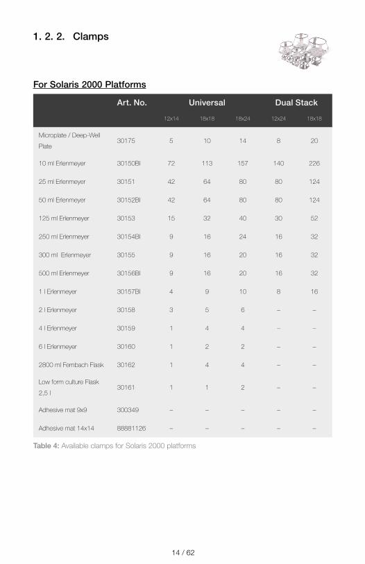
1. 2. 2. Clamps
For Solaris 2000 Platforms
Art. No. Universal Dual Stack
12x14 18x18 18x24 12x24 18x18
Microplate / Deep-Well
Plate30175 5 10 14 8 20
10 ml Erlenmeyer 30150BI 72 113 157 140 226
25 ml Erlenmeyer 30151 42 64 80 80 124
50 ml Erlenmeyer 30152BI 42 64 80 80 124
125 ml Erlenmeyer 30153 15 32 40 30 52
250 ml Erlenmeyer 30154BI 9 16 24 16 32
300 ml Erlenmeyer 30155 9 16 20 16 32
500 ml Erlenmeyer 30156BI 9 16 20 16 32
1 l Erlenmeyer 30157BI 4 9 10 8 16
2 l Erlenmeyer 30158 3 5 6 – –
4 l Erlenmeyer 30159 1 4 4 – –
6 l Erlenmeyer 30160 1 2 2 – –
2800 ml Fernbach Flask 30162 1 4 4 – –
Low form culture Flask
2,5 l30161 1 1 2 – –
Adhesive mat 9x9 300349 – – – – –
Adhesive mat 14x14 88881126 – – – – –
Table 4: Available clamps for Solaris 2000 platforms
15 / 62
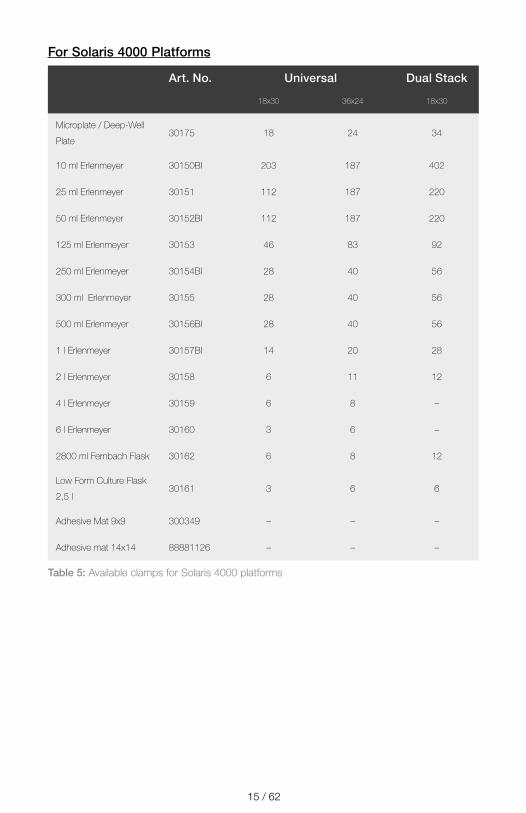
For Solaris 4000 Platforms
Art. No. Universal Dual Stack
18x30 36x24 18x30
Microplate / Deep-Well
Plate30175 18 24 34
10 ml Erlenmeyer 30150BI 203 187 402
25 ml Erlenmeyer 30151 112 187 220
50 ml Erlenmeyer 30152BI 112 187 220
125 ml Erlenmeyer 30153 46 83 92
250 ml Erlenmeyer 30154BI 28 40 56
300 ml Erlenmeyer 30155 28 40 56
500 ml Erlenmeyer 30156BI 28 40 56
1 l Erlenmeyer 30157BI 14 20 28
2 l Erlenmeyer 30158 6 11 12
4 l Erlenmeyer 30159 6 8 –
6 l Erlenmeyer 30160 3 6 –
2800 ml Fernbach Flask 30162 6 8 12
Low Form Culture Flask
2,5 l30161 3 6 6
Adhesive Mat 9x9 300349 – – –
Adhesive mat 14x14 88881126 – – –
Table 5: Available clamps for Solaris 4000 platforms

16 / 62
1. 2. 3. Test Tube Racks
For Solaris 2000 Platforms
Art. No. Universal Dual Stack
12x14 18x18 18x24 12x24 18x18
Half Size
10–13 mm,
Red, 6 x 6 Array30181 8 12 15 14 24
14–16 mm,
Orange, 6 x 6 Array30183 5 9 11 9 17
17–20 mm,
White, 4 x 5 Array30185 7 11 14 13 21
21–25 mm, Blue,
4 x 4 Array30187 6 9 11 10 17
26–30 mm, Green,
3 x 3 Array30189 6 9 12 11 18
Micro Centrifuge, 1.5 ml,
Blue, 4 x 6 Array30191 6 10 13 11 19
Full Size
10–13 mm, 6 x 12 Array 30180BI 3 7 10 6 13
14–16 mm, 6 x 12 Array 30182 3 4 6 6 8
17–20 mm, 4 x 10 Array 30184 3 5 7 6 8
21–25 mm, 4 x 10 Array 30186 2 3 5 4 6
26–30 mm, 3 x 8 Array 30188 3 4 6 5 8
1.5 mL Micro Centrifuge,
8 x 12 Array30190 3 5 7 6 9
Table 6: Available test tube racks for Solaris 2000 platforms
17 / 62
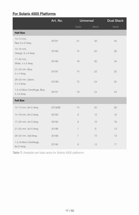
For Solaris 4000 Platforms
Art. No. Universal Dual Stack
18x30 36x24 18x30
Half Size
10–13 mm,
Red, 6 x 6 Array30181 21 32 40
14–16 mm,
Orange, 6 x 6 Array30183 14 20 26
17–20 mm,
White, 4 x 5 Array30185 18 20 34
21–25 mm, Blue,
4 x 4 Array30187 14 22 25
26–30 mm, Green,
3 x 3 Array30189 15 24 30
1.5 ml Micro Centrifuge, Blue,
4 x 6 Array30191 18 24 34
Full Size
10–13 mm, 6x12 Array 30180BI 14 20 26
14–16 mm, 6x12 Array 30182 9 12 16
17–20 mm, 4x10 Array 30184 9 15 18
21–25 mm, 4x10 Array 30186 7 9 13
26–30 mm, 3x8 Array 30188 7 10 13
1.5 ml Micro Centrifuge,
8x12 Array30190 9 12 17
Table 7: Available test tube racks for Solaris 4000 platforms

18 / 62
1. 3. Directives and StandardsRegion Directive Standards
Europe 2006/42/EC Machinery Directive
2014/35/EU Low Voltage (Protective Goals)
2014/30/EC
Electromagnetic Compatibility (EMC)
2011/65/EC RoHS
Directive on the Restriction of the use of certain Hazardous Substances in electrical and electronic equipment
EN 61010-1 3rd Edition
IEC 61010-2-051 3rd Edition
EN 61326-1 Class B
EN ISO 14971
EN ISO 9001
North America ANSI/UL 61010-1 3rd Edition
IEC 61010-2-051 3rd Edition
IEC 61326-1 Class B
CFR 47 FCC 15 EMC
EN ISO 14971
EN ISO 9001
Japan IEC 61010-1 3rd Edition
IEC 61010-2-051 3rd Edition
IEC 61326-1 Class B
EN ISO 14971
EN ISO 9001
Table 8: Directives and Standards
NOTE: This equipment has been tested and found to comply with the limits for a Class A digital device, pursuant to part 15 of the FCC Rules. These limits are designed to provide reasonable protection against harmful interference when the equipment is operated in a commercial environment. This equipment generates, uses, and can radiate radio frequency energy and, if not installed and used in accordance with the instruction manual, may cause harmful interference to radio communications. Operation of this equipment in a residential area is likely to cause harmful interference in which case the user will be required to correct the interference at his own expense.
19 / 62
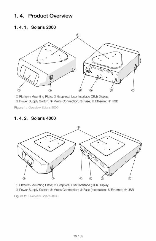
1. 4. Product Overview
1. 4. 1. Solaris 2000
➂➁ ➃
➀
➄ ➅ ➆
➀ Platform Mounting Plate; ➁ Graphical User Interface (GUI) Display; ➂ Power Supply Switch; ➃ Mains Connection; ➄ Fuse; ➅ Ethernet; ➆ USB
Figure 1: Overview Solaris 2000
1. 4. 2. Solaris 4000
➂➁ ➃
➀
➄ ➅ ➆
➀ Platform Mounting Plate; ➁ Graphical User Interface (GUI) Display; ➂ Power Supply Switch; ➃ Mains Connection; ➄ Fuse (resettable); ➅ Ethernet; ➆ USB
Figure 2: Overview Solaris 4000
20 / 62
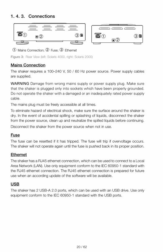
1. 4. 3. Connections
➀➀➁
➁ ➂ ➂
➀ Mains Connection; ➁ Fuse; ➂ Ethernet
Figure 3: Rear View (left: Solaris 4000, right: Solaris 2000)
Mains ConnectionThe shaker requires a 100–240 V, 50 / 60 Hz power source. Power supply cables are supplied.
WARNING Damage from wrong mains supply or power supply plug. Make sure that the shaker is plugged only into sockets which have been properly grounded. Do not operate the shaker with a damaged or an inadequately rated power supply cable.
The mains plug must be freely accessible at all times.
To eliminate hazard of electrical shock, make sure the surface around the shaker is dry. In the event of accidental spilling or splashing of liquids, disconnect the shaker from the power source, clean up and neutralize the spilled liquids before continuing.
Disconnect the shaker from the power source when not in use.
FuseThe fuse can be resetted if it has tripped. The fuse will trip if overvoltage occurs. The shaker will not operate again until the fuse is pushed back in its proper position.
EthernetThe shaker has a RJ45 ethernet connection, which can be used to connect to a Local Area Network (LAN). Use only equipment conform to the IEC 60950-1 standard with the RJ45 ethernet connection. The RJ45 ethernet connection is prepared for future use when an according update of the software will be available.
USBThe shaker has 2 USB-A 2.0 ports, which can be used with an USB drive. Use only equipment conform to the IEC 60950-1 standard with the USB ports.

21 / 62
2. Transport and Set Up
NOTICE
It is your responsibility to make sure that the shaker is set up properly.
The shipping carton should be inspected upon delivery. When received, carefully examine for any shipping damage before unpacking. If damage is discovered, the delivering carrier should specify and sign for the damage on your copy of the delivery receipt.
Open the carton carefully making certain that all parts (“Table 9: Items Supplied”) are accounted for before packaging materials are discarded. After unpacking, if damage is found, report it to the carrier and request a damage inspection.
Important: Failure to request an inspection of damage within a few days after receipt of shipment absolves the carrier from any liability for damage. You must call for a damage inspection.
2. 1. UnpackingUse the packing list when unpacking to verify that the complete unit has been received. Do not discard packing materials until all is accounted for.
Items SuppliedItem Quantity
Shaker 1
Power Supply Cable 1
Universal Platform 1
Screws for Platform 3
Thread Locker 1
Manuals print en 1
Manuals on USB 1
Table 9: Items Supplied
If any items are missing, contact Thermo Fisher Scientific.
22 / 62
2. 2. LocationCAUTION Protection can be impaired due to reduced stability of plastic exposed to ultraviolet rays. Do not subject the shaker and plastic accessories to direct sunlight or other sources of ultraviolet rays.
Put the shaker on a level table or bench capable of supporting the weight of the shaker with any accessories and samples while in operation. Place the shaker near an electrical outlet that matches the nameplate requirements. Allow clearance around the unit for free air convection, accessory attachments and user convenience.
Mind the following requirements for setting up the unit:
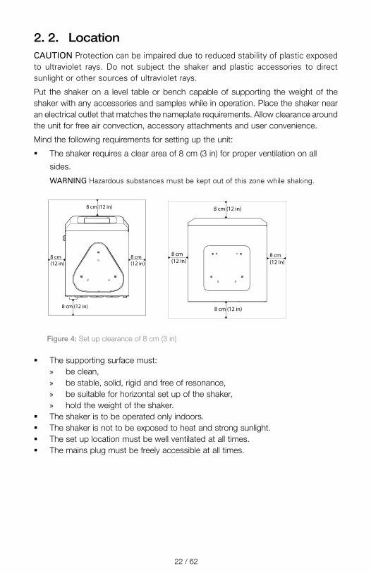
� The shaker requires a clear area of 8 cm (3 in) for proper ventilation on all
sides.
WARNING Hazardous substances must be kept out of this zone while shaking.
8 cm (12 in)
8 cm (12 in)
8 cm (12 in)
8 cm(12 in)
8 cm (12 in)
8 cm (12 in)
8 cm (12 in)
8 cm (12 in)
Figure 4: Set up clearance of 8 cm (3 in)
� The supporting surface must: » be clean, » be stable, solid, rigid and free of resonance, » be suitable for horizontal set up of the shaker, » hold the weight of the shaker.
� The shaker is to be operated only indoors. � The shaker is not to be exposed to heat and strong sunlight. � The set up location must be well ventilated at all times. � The mains plug must be freely accessible at all times.
23 / 62
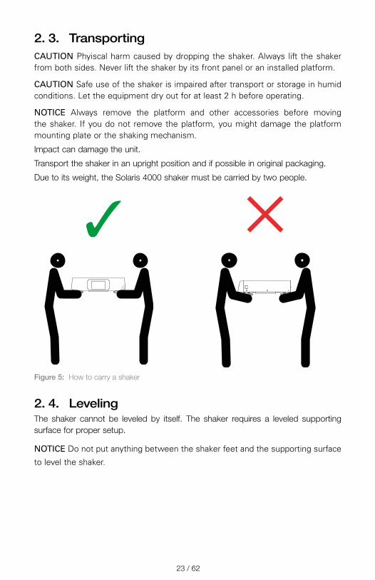
2. 3. TransportingCAUTION Phyiscal harm caused by dropping the shaker. Always lift the shaker from both sides. Never lift the shaker by its front panel or an installed platform.
CAUTION Safe use of the shaker is impaired after transport or storage in humid conditions. Let the equipment dry out for at least 2 h before operating.
NOTICE Always remove the platform and other accessories before moving the shaker. If you do not remove the platform, you might damage the platform mounting plate or the shaking mechanism.
Impact can damage the unit.
Transport the shaker in an upright position and if possible in original packaging.
Due to its weight, the Solaris 4000 shaker must be carried by two people.
Figure 5:
✓ ✕
How to carry a shaker
2. 4. LevelingThe shaker cannot be leveled by itself. The shaker requires a leveled supporting surface for proper setup.
NOTICE Do not put anything between the shaker feet and the supporting surface
to level the shaker.
24 / 62
2. 5. Mains ConnectionThe shaker requires a 100–240 V, 50 / 60 Hz power source. Power supply cables are supplied.
WARNING Damage from wrong mains supply or power supply plug. Make sure that the shaker is plugged only into sockets which have been properly grounded. Do not operate the shaker with a damaged or an inadequately rated power supply cable.
To connect the shaker to the power supply follow this procedure:
1. Turn off the power supply switch located on the right side.
2. Make sure that the cable specification agrees with the safety standards of your
country.
3. Make sure that the voltage and frequency are the same as the figures on the
rating plate.
The mains plug must be freely accessible at all times.
To eliminate hazard of electrical shock, make sure the surface around the shaker is dry. In the event of accidental spilling or splashing of liquids, disconnect the shaker from the power source, clean up and neutralize the spilled liquids before continuing.
Disconnect the shaker from the power source when not in use.
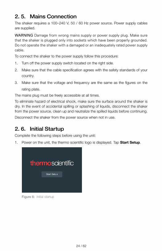
2. 6. Initial StartupComplete the following steps before using the unit:
1. Power on the unit, the thermo scientific logo is displayed. Tap Start Setup.
Figure 6: Initial startup

25 / 62
2. Select the desired language on the Language screen. Tap Next.
Figure 7: Initial startup - language
3. Enter the unit name on the Unit Name dialog box. Tap Next.
Figure 8: Initial startup - unit name
4. Enter city and country in the text field. You can also select from a list of
suggestions displayed while making your entry. Tap Next.
Figure 9: Initial startup - region
26 / 62
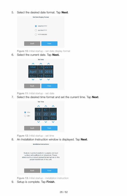
5. Select the desired date format. Tap Next.
Figure 10: Initial startup - set date display format6. Select the current date. Tap Next�
Figure 11: Initial startup - set date7. Select the desired time format and set the current time. Tap Next.
Figure 12: Initial startup - set time8. An Installation Instruction window is displayed. Tap Next.
Figure 13: Initial startup - installation instruction9. Setup is complete. Tap Finish.

27 / 62
2. 7. Storage
CAUTION
When you remove the shaker and accessories from use, clean and, if necessary, disinfect or decontaminate the full system. Do not leave the shaker and acessories in an undefined state of contamination. If you are unsure of the process contact the Thermo Fisher Scientific customer service (“Cleaning” on page 54, “Disinfection” on page 55 and “Decontamination” on page 55).
� Before storing the shaker and the accessories, it must be cleaned and, if necessary, disinfected and decontaminated.
� Shaker and accessories must be completely dry before storage. � Keep the shaker in a clean, dust-free location. � Keep the shaker on its feet. � Do not store the shaker in direct sunlight.
2. 8. Shipping
CAUTION
Before shipping the shaker and accessories you must clean and, if necessary, disinfect or decontaminate the full system. Do not leave the shaker and acessories in an undefined state of contamination. If you are unsure of the process contact the Thermo Fisher Scientific customer service (“Cleaning” on page 54, “Disinfection” on page 55 and “Decontamination” on page 55).
Before shipping the shaker:
� The shaker must be clean and decontaminated. � You must confirm the decontamination with a decontamination certificate. A
decontamination certificate can be retrieved from the Thermo Fisher Scientific customer service.
28 / 62
3. Operation
3. 1. Power on / offPush the power switch at the right side to power the shaker on (I) or off (0).
The touchscreen shows the Thermo Scientific logo while booting.
When ready, the touchscreen shows the current status of the shaker.
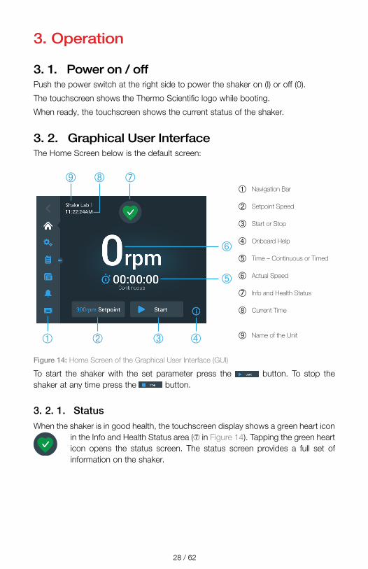
3. 2. Graphical User InterfaceThe Home Screen below is the default screen:
➀ Navigation Bar
➁ Setpoint Speed
➂ Start or Stop
➃ Onboard Help
➄ Time – Continuous or Timed
➅ Actual Speed
➆ Info and Health Status
➇ Current Time
➈ Name of the Unit
Figure 14: Home Screen of the Graphical User Interface (GUI)
To start the shaker with the set parameter press the button. To stop the shaker at any time press the button.
3. 2. 1. StatusWhen the shaker is in good health, the touchscreen display shows a green heart icon
in the Info and Health Status area (➆ in Figure 14). Tapping the green heart icon opens the status screen. The status screen provides a full set of information on the shaker.

29 / 62
AlertWhen an alert is issued, the touchscreen display shows a yellow bar on top of the current screen. After a short time, the yellow alert bar goes away. Only the yellow triangle indicates that alerts exists for the shaker, The triangle icon has a blue circle with a white border that shows the number of active alerts. Tapping the triangle icon in the Info & Health Status area (➆ in Figure 14) opens a screen listing all alerts that are currently active. The latest alert appears expanded to let you view the full details. You can scroll through the list and tap on any list item to expand it and read more.
AlarmWhen an alarm is issued, the shaker stops immediately to avoid damage to the
samples and/or the unit itself. You must acknowledge the message on the touchscreen before you can continue operation.
When an alarm is issued, the touchscreen display shows a red bar on top of the current screen. The Info & Health Status area (➆ in Figure 14) displays a red alarm bell enclosed by sound waves. Additionally, an audible alarm tone constantly sounds. This can be configured to be silent. (“Alarms and Alerts” on page 30)
Beneath the red alarm bar, a ticker-style message explains the root cause of the problem and provides instructions on how to handle the alarm. A Snooze button appears, allowing you to temporarily silence the alarm. When the alarm condition is not cleared within the snooze period, the audible alarm returns. The duration of the snooze period can be chosen in the settings
ErrorWhen an error occurs, the shaker stops immediately to avoid damage to the samples and/or the unit itself. The screen is completely filled with a red error message.
You must correct the root cause and restart the shaker by powering it off and on before you can start operation again. Refer to “Troubleshooting” on page 58 for the list of error messages.
30 / 62
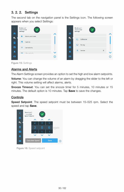
3. 2. 2. SettingsThe second tab on the navigation panel is the Settings icon. The following screen appears when you select Settings:
Figure 15: Settings
Alarms and AlertsThe Alarm Settings screen provides an option to set the high and low alarm setpoints.
Volume: You can change the volume of an alarm by dragging the slider to the left or right. This volume setting will affect alarms, alerts.
Snooze Timeout: You can set the snooze timer for 5 minutes, 10 minutes or 15 minutes. The default option is 10 minutes. Tap Save to save the changes.
ControlsSpeed Setpoint: The speed setpoint must be between 15–525 rpm. Select the speed and tap Save.
Figure 16: Speed setpoint
31 / 62
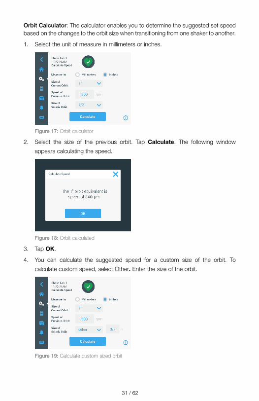
Orbit Calculator: The calculator enables you to determine the suggested set speed based on the changes to the orbit size when transitioning from one shaker to another.
1. Select the unit of measure in millimeters or inches.
Figure 17: Orbit calculator
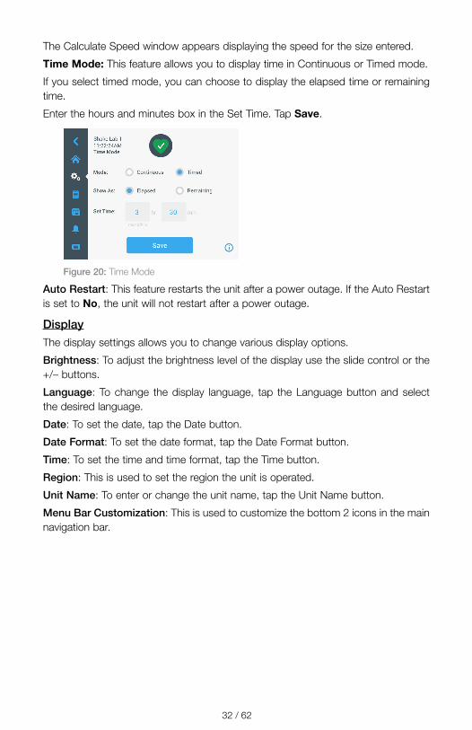
2. Select the size of the previous orbit. Tap Calculate. The following window
appears calculating the speed.
Figure 18: Orbit calculated
3. Tap OK.
4. You can calculate the suggested speed for a custom size of the orbit. To
calculate custom speed, select Other� Enter the size of the orbit.
Figure 19: Calculate custom sized orbit
32 / 62
The Calculate Speed window appears displaying the speed for the size entered.
Time Mode: This feature allows you to display time in Continuous or Timed mode.
If you select timed mode, you can choose to display the elapsed time or remaining time.
Enter the hours and minutes box in the Set Time. Tap Save.
Figure 20: Time Mode
Auto Restart: This feature restarts the unit after a power outage. If the Auto Restart is set to No, the unit will not restart after a power outage.
DisplayThe display settings allows you to change various display options.
Brightness: To adjust the brightness level of the display use the slide control or the +/– buttons.
Language: To change the display language, tap the Language button and select the desired language.
Date: To set the date, tap the Date button.
Date Format: To set the date format, tap the Date Format button.
Time: To set the time and time format, tap the Time button.
Region: This is used to set the region the unit is operated.
Unit Name: To enter or change the unit name, tap the Unit Name button.
Menu Bar Customization: This is used to customize the bottom 2 icons in the main navigation bar.

33 / 62
Figure 21: Menu Bar Customization
Sleep Mode: This is used to put the display to sleep after 15 minutes of inactivity.
Files and InfoThis provides information of the serial number, H.M.I. (Human-Machine Interface), main controller and parameter. You can factory reset your settings from this screen. Resetting to factory defaults will erase all settings except event log and usage.
Figure 22: Files and Info
ServiceThe service settings are restricted and can be accessed by authorized service technicians. The authorized service technician can update the firmware.
3. 2. 3. ProgramsPrograms displays the list of programs. You can create, edit, delete, import and export a program. The following screen displays the programs created:
34 / 62
Figure 23: Programs
The eye icon allows you to view the program.
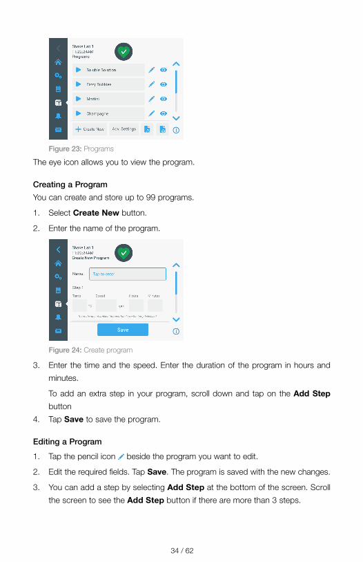
Creating a Program
You can create and store up to 99 programs.
1. Select Create New button.
2. Enter the name of the program.
Figure 24: Create program
3. Enter the time and the speed. Enter the duration of the program in hours and
minutes.
To add an extra step in your program, scroll down and tap on the Add Step
button
4. Tap Save to save the program.
Editing a Program
1. Tap the pencil icon beside the program you want to edit.
2. Edit the required fields. Tap Save. The program is saved with the new changes.
3. You can add a step by selecting Add Step at the bottom of the screen. Scroll
the screen to see the Add Step button if there are more than 3 steps.
35 / 62
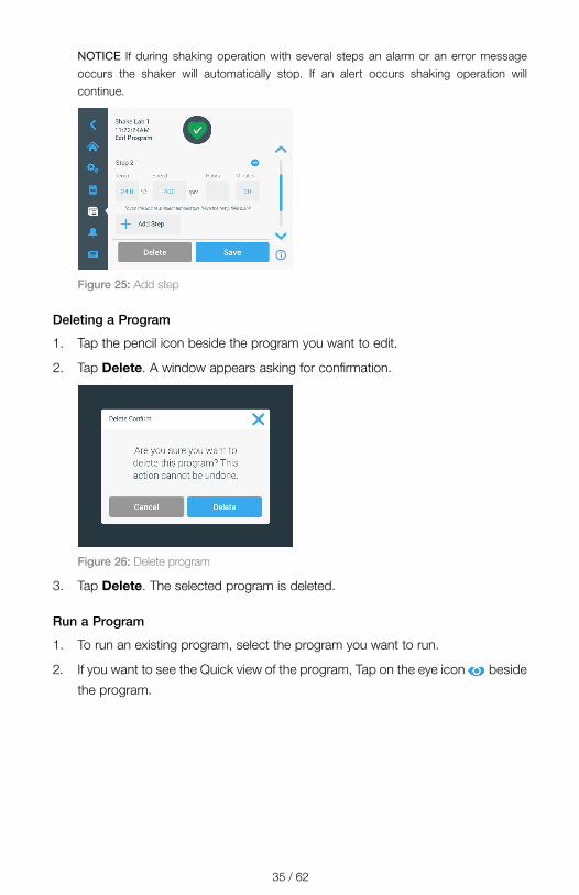
NOTICE If during shaking operation with several steps an alarm or an error message occurs the shaker will automatically stop. If an alert occurs shaking operation will continue.
Figure 25: Add step
Deleting a Program
1. Tap the pencil icon beside the program you want to edit.
2. Tap Delete. A window appears asking for confirmation.
Figure 26: Delete program
3. Tap Delete. The selected program is deleted.
Run a Program
1. To run an existing program, select the program you want to run.
2. If you want to see the Quick view of the program, Tap on the eye icon beside
the program.
36 / 62
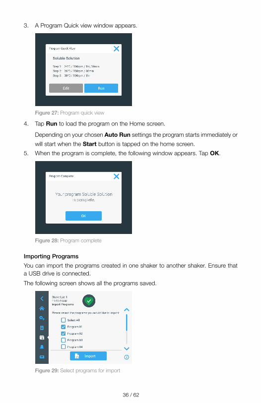
3. A Program Quick view window appears.
Figure 27: Program quick view
4. Tap Run to load the program on the Home screen.
Depending on your chosen Auto Run settings the program starts immediately or
will start when the Start button is tapped on the home screen.
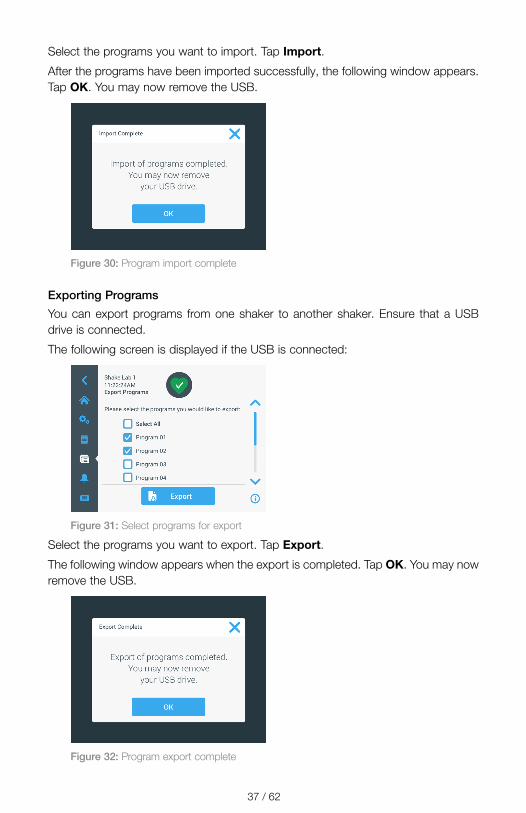
5. When the program is complete, the following window appears. Tap OK.
Figure 28: Program complete
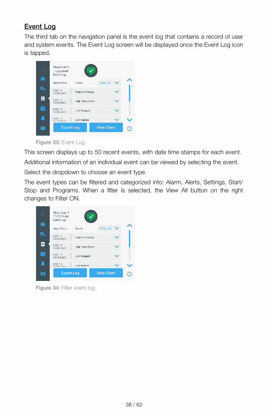
Importing Programs
You can import the programs created in one shaker to another shaker. Ensure that a USB drive is connected.
The following screen shows all the programs saved.
Figure 29: Select programs for import
37 / 62
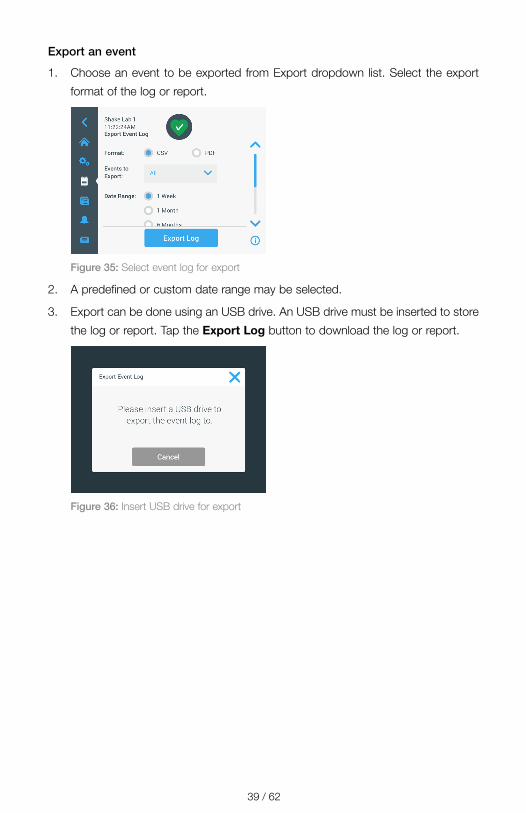
Select the programs you want to import. Tap Import.
After the programs have been imported successfully, the following window appears. Tap OK. You may now remove the USB.
Figure 30: Program import complete
Exporting Programs
You can export programs from one shaker to another shaker. Ensure that a USB drive is connected.
The following screen is displayed if the USB is connected:
Figure 31: Select programs for export
Select the programs you want to export. Tap Export.
The following window appears when the export is completed. Tap OK. You may now remove the USB.
Figure 32: Program export complete
38 / 62
Event LogThe third tab on the navigation panel is the event log that contains a record of user and system events. The Event Log screen will be displayed once the Event Log icon is tapped.
Figure 33: Event Log
This screen displays up to 50 recent events, with date time stamps for each event.
Additional information of an individual event can be viewed by selecting the event.
Select the dropdown to choose an event type.
The event types can be filtered and categorized into: Alarm, Alerts, Settings, Start/Stop and Programs. When a filter is selected, the View All button on the right changes to Filter ON.
Figure 34: Filter event log
39 / 62
Export an event
1. Choose an event to be exported from Export dropdown list. Select the export
format of the log or report.
Figure 35: Select event log for export
2. A predefined or custom date range may be selected.
3. Export can be done using an USB drive. An USB drive must be inserted to store
the log or report. Tap the Export Log button to download the log or report.
Figure 36: Insert USB drive for export

40 / 62
ChartsCharts display speed data in graphs. The X-axis displays the time and Y-axis displays the speed.
Figure 37: Charts
Editing the Chart
1. Tap Edit if you want to edit the chart.
2. You can select the date range and the time range.
3. Tap Save to save the changes or custom settings
4. Tap Export Chart Data to download speed chart. Export can be done using an
USB drive. Ensure that an USB drive is inserted to export the data.
41 / 62
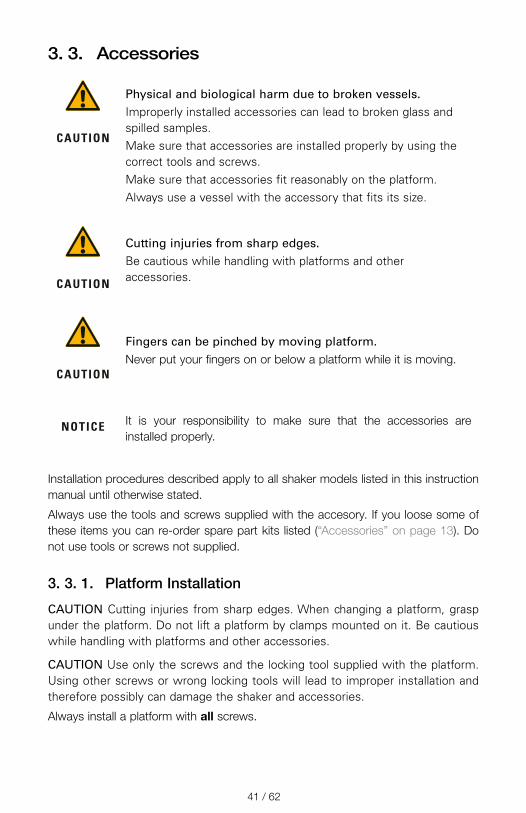
3. 3. Accessories
CAUTION
Physical and biological harm due to broken vessels.Improperly installed accessories can lead to broken glass and spilled samples.Make sure that accessories are installed properly by using the correct tools and screws.Make sure that accessories fit reasonably on the platform.Always use a vessel with the accessory that fits its size.
CAUTION
Cutting injuries from sharp edges.Be cautious while handling with platforms and other accessories.
CAUTION
Fingers can be pinched by moving platform.Never put your fingers on or below a platform while it is moving.
NOTICE It is your responsibility to make sure that the accessories are installed properly.
Installation procedures described apply to all shaker models listed in this instruction manual until otherwise stated.
Always use the tools and screws supplied with the accesory. If you loose some of these items you can re-order spare part kits listed (“Accessories” on page 13). Do not use tools or screws not supplied.
3. 3. 1. Platform Installation
CAUTION Cutting injuries from sharp edges. When changing a platform, grasp under the platform. Do not lift a platform by clamps mounted on it. Be cautious while handling with platforms and other accessories.
CAUTION Use only the screws and the locking tool supplied with the platform. Using other screws or wrong locking tools will lead to improper installation and therefore possibly can damage the shaker and accessories.
Always install a platform with all screws.
42 / 62
Always use the proper locking tool:
� 3/16” locking tool (GT530066) for all Solaris 2000 platforms � 7/32” locking tool (GT530080) for all Solaris 4000 platforms
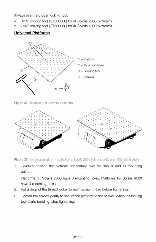
Universal Platforms
➀
➁
➂
➃
➀ – Platform
➁ – Mounting holes
➂ – Locking tool
➃ – Screws
Figure 38: Example of an universal platform
Figure 39: Universal platform installed on a Solaris 2000 (left) and a Solaris 4000 (right) shaker
1. Carefully position the platform horizontally over the shaker and its mounting
points.
Platforms for Solaris 2000 have 3 mounting holes, Platforms for Solaris 4000
have 4 mounting holes.
2. Put a drop of the thread locker to each screw thread before tightening.
3. Tighten the screws gently to secure the platform to the shaker. When the locking
tool starts bending, stop tightening.

43 / 62
Dual Stack Platforms
➀
➁
➂
➃
➃
➃
➄➅
➆
➀ – Upper platform (no pinch protection)
➁ – Lower platform (with pinch protection)
➂ – Pillars (4x)
➃ – Screws for mounting the pillars (4x for upper platform and 4x lower platform)
➄ – Mounting holes
➅ – Locking tool
➆ – Screws for connecting the platform to the platform mounting plate on the shaker
Figure 40: Dual Stack Platform Assembly
Connect the upper and the lower platform by mounting them with the 4 pillars in each corner. Mount the pillars with the proper screws from the upper and from the lower platform. Put a drop of the thread locker to each screw thread before tightening.
Tighten the screws gently to connect the pillar and the platforms. When the locking tool starts bending, stop tightening.
The lower platform is the one with the mounting holes for connecting it to the shaker. Make sure to have the lower platform on the bottom side when assembling.
NOTICE Before placing vessels on the platform assembly, make a final check to be sure that the platform assembly does not wobble.
44 / 62
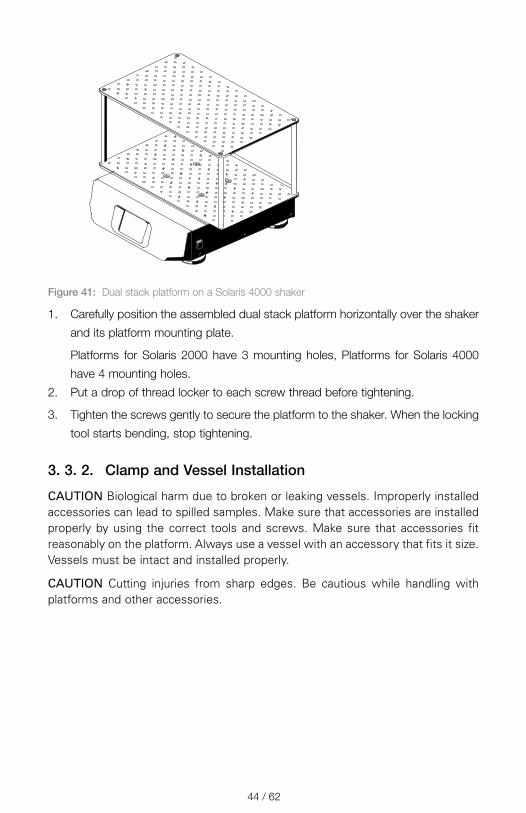
Figure 41: Dual stack platform on a Solaris 4000 shaker
1. Carefully position the assembled dual stack platform horizontally over the shaker
and its platform mounting plate.
Platforms for Solaris 2000 have 3 mounting holes, Platforms for Solaris 4000
have 4 mounting holes.
2. Put a drop of thread locker to each screw thread before tightening.
3. Tighten the screws gently to secure the platform to the shaker. When the locking
tool starts bending, stop tightening.
3. 3. 2. Clamp and Vessel Installation
CAUTION Biological harm due to broken or leaking vessels. Improperly installed accessories can lead to spilled samples. Make sure that accessories are installed properly by using the correct tools and screws. Make sure that accessories fit reasonably on the platform. Always use a vessel with an accessory that fits it size. Vessels must be intact and installed properly.
CAUTION Cutting injuries from sharp edges. Be cautious while handling with platforms and other accessories.
45 / 62
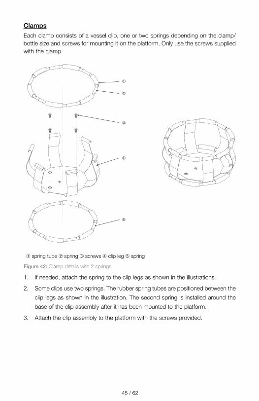
ClampsEach clamp consists of a vessel clip, one or two springs depending on the clamp/bottle size and screws for mounting it on the platform. Only use the screws supplied with the clamp.
➀
➁
➂
➃
➄
➀ spring tube ➁ spring ➂ screws ➃ clip leg ➄ spring
Figure 42: Clamp details with 2 springs
1. If needed, attach the spring to the clip legs as shown in the illustrations.
2. Some clips use two springs. The rubber spring tubes are positioned between the
clip legs as shown in the illustration. The second spring is installed around the
base of the clip assembly after it has been mounted to the platform.
3. Attach the clip assembly to the platform with the screws provided.
46 / 62
Vessel1. Carefully place the desired vessel in the clamp by first
pulling the clamp spring far enough apart to enable the vessel base to be positioned inside the clamp. Gently slide the vessel into its proper position, securing it to the wider bottom of the clamp. The spring will hold the neck of the vessel securely in place.
» Each clamp contains a support spring located at the narrow top of the clamp.
» Depending on the size of the clamp, the clamp base may contain one or several screws necessary to secure the clamp to the platform. All screws provided with the clamp must be properly attached to the platform.
2. Make sure all vessel are securely clamped before powering on the unit.
Wherever possible, vessel should contain a stopper to prevent hazardous substances being thrown out during the mixing action.
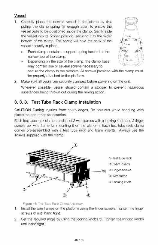
3. 3. 3. Test Tube Rack Clamp Installation
CAUTION Cutting injuries from sharp edges. Be cautious while handling with platforms and other accessories.
Each test tube rack clamp consists of 2 wire frames with a locking knob and 2 finger screws per wire frame for mounting it on the platform. Each test tube rack clamp comes pre-assembled with a test tube rack and foam insert(s). Always use the screws supplied with the clamp.
➂➁
➃
➀
➄
➀ Test tube rack
➁ Foam inserts
➂ Finger screws
➃ Wire frame
➄ Locking knob
Figure 43: Test Tube Rack Clamp Assembly1. Install the wire frames on the platform using the finger screws. Tighten the finger
screws ➂ until hand tight.
2. Set the required angle by using the locking knobs ➄. Tighten the locking knobs until hand tight.

47 / 62
3. 3. 4. Microplate / Deepwell-Plate Installation
CAUTION Cutting injuries from sharp edges. Be cautious while handling with platforms and other accessories.
1. Place the microplate frame on the platform.
2. Mount the microplate frame to the platform using the screws supplied with the
microplate / deepwell-plate set.
3. Insert the microplate or deepwell-plate into the microplate frame.
4. Make sure that the microplate or deepwell-plate sits tight by lifting it gently. If it
sits tight, it is installed properly.
➀
➂
➁
➀ Deepwell Plate
➁ Screw
➂ Microplate Clamp
Figure 44: Microplate / Deepwell-plate assembly
48 / 62
3. 4. Loading and Normal Use
WARNING
Risk of fire due to triggered chemical reactions.Do not operate the shaker at speeds that will cause the contents of vessels to be thrown out.Increase speed slowly. Try with water before using chemicals.
CAUTION
Safety can be impaired by improper loading and damaged accessories. � Make sure that the load (accessories and samples) is
arranged symmetrically to the center of the platform. When operating a dual stack platform, make sure that the lower platform carries more load than the upper platform.
� Never overload the shaker. For maximum load refer to „Technical Data“ on page 11. The load contains the weight of the platform, accessories and samples installed on the shaker.
� Make sure that the accessories are installed properly before operating the shaker. Follow the instructions in section „Accessories“ on page 41.
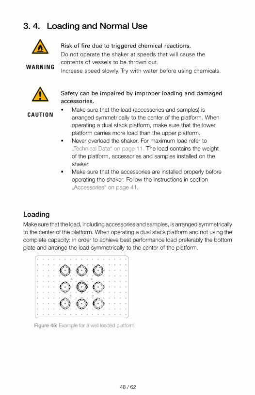
LoadingMake sure that the load, including accessories and samples, is arranged symmetrically to the center of the platform. When operating a dual stack platform and not using the complete capacity: in order to achieve best performance load preferably the bottom plate and arrange the load symmetrically to the center of the platform.
Figure 45: Example for a well loaded platform
49 / 62
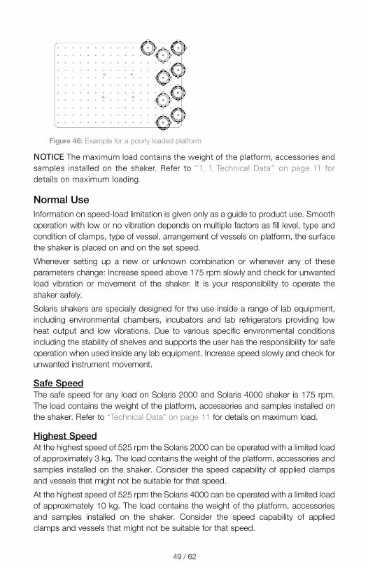
Figure 46: Example for a poorly loaded platform
NOTICE The maximum load contains the weight of the platform, accessories and samples installed on the shaker. Refer to “1. 1. Technical Data” on page 11 for details on maximum loading.
Normal UseInformation on speed-load limitation is given only as a guide to product use. Smooth operation with low or no vibration depends on multiple factors as fill level, type and condition of clamps, type of vessel, arrangement of vessels on platform, the surface the shaker is placed on and on the set speed.
Whenever setting up a new or unknown combination or whenever any of these parameters change: Increase speed above 175 rpm slowly and check for unwanted load vibration or movement of the shaker. It is your responsibility to operate the shaker safely.
Solaris shakers are specially designed for the use inside a range of lab equipment, including environmental chambers, incubators and lab refrigerators providing low heat output and low vibrations. Due to various specific environmental conditions including the stability of shelves and supports the user has the responsibility for safe operation when used inside any lab equipment. Increase speed slowly and check for unwanted instrument movement.
Safe SpeedThe safe speed for any load on Solaris 2000 and Solaris 4000 shaker is 175 rpm. The load contains the weight of the platform, accessories and samples installed on the shaker. Refer to “Technical Data” on page 11 for details on maximum load.
Highest SpeedAt the highest speed of 525 rpm the Solaris 2000 can be operated with a limited load of approximately 3 kg. The load contains the weight of the platform, accessories and samples installed on the shaker. Consider the speed capability of applied clamps and vessels that might not be suitable for that speed.
At the highest speed of 525 rpm the Solaris 4000 can be operated with a limited load of approximately 10 kg. The load contains the weight of the platform, accessories and samples installed on the shaker. Consider the speed capability of applied clamps and vessels that might not be suitable for that speed.

50 / 62
NOTICE Always mind that with rising speed clamps will start opening and deliver
additional temporary vibration to the system due to greater vessel movement.
Charts Following charts will guide you in setting up the best speed-load combination for your normal use. The green area shows speed-load combinations that cause none to minor vibration during shaking operation. The red area shows speed-load combinations that may cause strong vibration during shaking operation and can result in unwanted movement of the shaker. As these charts are for guidance only, you must pay attention when your speed-load combination comes closer to the red area.
Be aware that your specific application conditions may cause unwanted load or instrument behaviour before reaching the shown borderline. Increase the speed gradually to explore the behaviour of your specific load. The load contains the weight of the platform, accessories and samples installed on the shaker.
Solaris 2000
Figure 47:
0
5
10
15
20
25
30
35
40
45
0 50 100 150 200 250 300 350 400 450 500 550
kg
rpm
Empty weight of platforms 18x18 Dual Stack (SK1818D) 12x14 Dual Stack (SK1214D) 18x24 (SK1824)
18x18 (SK1818) 12x14 (SK1214)
Solaris 2000 – Normal Use

51 / 62
Solaris 4000
Figure 48:
0
5
10
15
20
25
30
35
40
45
0 50 100 150 200 250 300 350 400 450 500 550
kg
rpm
Empty weight of platforms 18x30 Dual Stack (SK1830D) 36x24 (SK3624) 18x30 (SK1830
Solaris 4000 – Normal Use

52 / 62
4. Maintenance and Care
WARNING
Risk from handling hazardous substances � If shaking any hazardous materials mind the
“Laboratory Biosafety Manual” of the World Health Organization (WHO) and any local regulations. When shaking microbiological samples from the Risk Group II (according to the “Laboratory Biosafety Manual” of the World Health Organization (WHO)), aerosol-tight biological seals have to be used. Look on the internet page of the World Health Organization (www.who.int) for the “Laboratory Biosafety Manual”. For materials in a higher risk group, extra safety measures must be taken.
� If toxins or pathogenic substances have contaminated the shaker or its parts, appropriate disinfection measures have to be taken (“Decontamination” on page 55; „Disinfection“ on page 55).
� If a hazardous situation occurs, turn off the power supply to the shaker and leave the area immediately.
WARNING
Damage to health from infectious substancesIf an accidental spill places liquids or other materials under the platform, immediately power off the shaker, unplug it, and remove the platform (“Platforms” on page 13).Clean up the spill following your regular laboratory procedures. Use proper personal protective equipment.
Any internal adjustments or repairs must be performed by an authorized service technician. The shaker housing is not to be opened by the user.
Follow any product information supplied with the according accessory stating specific details on how to maintain and clean it properly. Use the following information within this chapter only as guideline.

53 / 62
4. 1. BasicsFor the sake of personal, environmental, and material protection, you must clean and if necessary disinfect the shaker and its accessories on a regular basis.
Thermo Fisher Scientific recommends cleaning and manually disinfecting your laboratory shaker at least once each month. Normal indoor air contains thousands of circulating microorganisms which can take up residence in your shaker, putting your cultures at risk.
Thermo Fisher Scientific recommends using 70% ethanol, or 70% isopropanol or 10% or less quaternary ammonium based disinfectant.
NOTICE The mechanism can be damaged by entering liquids. Do not allow liquids, especially organic solvents, to get in contact with the mechanism or the mechanism bearing. Organic solvents break down the grease in the mechanisms bearing.
NOTICE Not rated procedures or agents could deteriorate the materials of the shaker and lead to malfunction. Refrain from using any other cleaning or decontamination procedure, if you are not entirely sure that the intended procedure is safe for the equipment. Use only cleaning agents that will not damage the equipment. If in doubt contact the manufacturer of the cleaning agent.
� Pull out the power supply plug before cleaning, disinfecting or decontaminating.
� Remove installed accessories and platform(s) from shaker before cleaning, disinfecting or decontaminating.
� Use warm water with a mild detergent with a soft cloth to clean the materials. If in doubt contact Thermo Fisher Scientific. Rinse off with clean water and dry thoroughly.
� Never use caustic cleaning agents such as phosphoric acid, bleaching solutions or scrubbing powder.
� Use only disinfectants with a pH of 6–8. � Clean up any spills immediately using a lint-free cloth dampened with a
noncorrosive cleaner as instructed by the manufacturer of the cleaning agent. � Spills can seep under the platform. If any spills get beneath the platform,
uninstall the platform and clean up the spill. � Check the shaker parts and remove any spilled growth media or debris.
Inspection of Accessories
NOTICE Do not run any shaker or accessories with signs of damage. It is recommend that you have accessories inspected on a regular basis as part of your routine service to ensure safety.
After thoroughly cleaning the accessories, they must be inspected for damage, wear and corrosion.
54 / 62
Metal PartsIn case of damage, such as corrosion, wear or cracks, the accessories must be removed from service immediately.
Plastic PartsCheck for signs of crazing, fading, bruising or cracking. In case of damage the inspected item must be removed from service immediately.
4. 2. CleaningNOTICE Before using any cleaning methods, users should check with the manufacturer of the cleaning agents that the proposed method will not damage the equipment.
NOTICE The mechanism can be damaged by entering liquids. Do not allow liquids, especially organic solvents, to get on the mechanism or the mechanism bearing. Organic solvents break down the grease in the mechanisms bearing.Wash the exterior of the unit with a soft cloth using a solution of mild soap and water, rinse off with clean water and dry thoroughly.
Suggested with every 3 months of constant use.
Refer to “Basics” on page 53 for proper cleaning of the shaker and the used accessories.
TouchscreenTo clean the touchscreen:
1. Pull out the power supply plug.
2. Clean the touchscreen using a dry microfiber cloth.
3. If necessary moisten the microfiber cloth with water and wipe the touchscreen
again.

55 / 62
4. 3. DisinfectionWARNING Risk from handling hazardous substances. Do not touch infected parts. Hazardous infection is possible when touching the contaminated parts. Infectious material can get into the shaker when a vessel breaks or as a result of spills. In case of contamination, make sure that no one is put at risk. Disinfect the affected parts immediately.
NOTICE Equipment can be damaged by inappropriate disinfection methods or agents. Make sure that the disinfection agent or the method will not damage the equipment. In doubt contact the manufacturer of the disinfection agent. Observe the safety precautions and handling instructions for the disinfection agents used.
1. Wipe all parts and areas with 70% ethanol as required by the level of disinfection
you need. Do not wet any areas with exposed electronics.
2. Allow to air dry.
You are responsible that the level of disinfection is achieved according to your requirements.
4. 4. DecontaminationWARNING Risk from handling hazardous substances. Do not touch contaminated parts. Exposure to contamination is possible when touching the contaminated parts. Contaminated material can get into the shaker when a tube breaks or as a result of spills. In case of contamination, make sure that no one is put at risk. Decontaminate the affected parts immediately.
NOTICE Equipment can be damaged by inappropriate decontamination methods or agents. Make sure that the decontamination agent or the method will not damage the equipment. If in doubt contact the manufacturer of the decontamination agent. Observe the safety precautions and handling instructions for the decontamination agents used.
The following method is suggested by Thermo Fisher Scientific.
1. Wipe all parts and areas with 70% ethanol. Do not wet any areas with exposed
electronics.
2. Allow to air dry.
You are responsible that the level of decontamination is achieved according to your requirements.
56 / 62
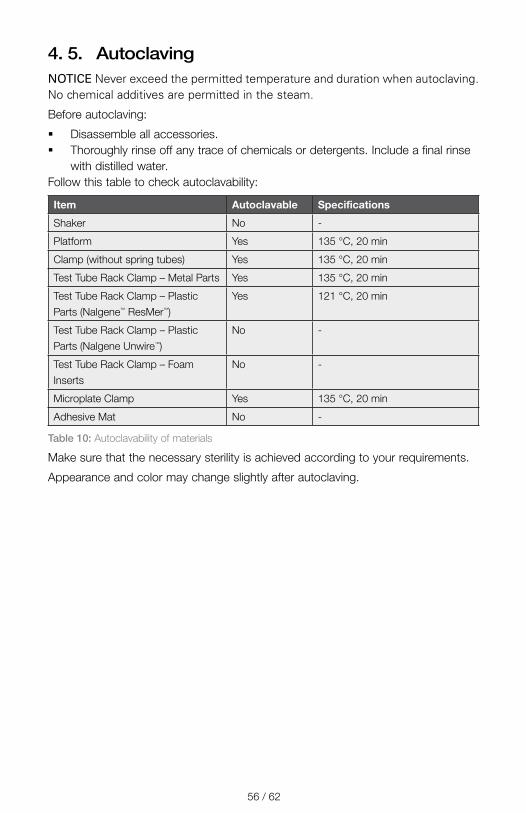
4. 5. AutoclavingNOTICE Never exceed the permitted temperature and duration when autoclaving. No chemical additives are permitted in the steam.
Before autoclaving:
� Disassemble all accessories. � Thoroughly rinse off any trace of chemicals or detergents. Include a final rinse
with distilled water.Follow this table to check autoclavability:
Item Autoclavable Specifications
Shaker No -
Platform Yes 135 °C, 20 min
Clamp (without spring tubes) Yes 135 °C, 20 min
Test Tube Rack Clamp – Metal Parts Yes 135 °C, 20 min
Test Tube Rack Clamp – Plastic Parts (Nalgene™ ResMer™)
Yes 121 °C, 20 min
Test Tube Rack Clamp – Plastic Parts (Nalgene Unwire™)
No -
Test Tube Rack Clamp – Foam Inserts
No -
Microplate Clamp Yes 135 °C, 20 min
Adhesive Mat No -
Table 10: Autoclavability of materials
Make sure that the necessary sterility is achieved according to your requirements.
Appearance and color may change slightly after autoclaving.
57 / 62
4. 6. ServiceThermo Fisher Scientific recommends having the shaker and accessories serviced once per year by an authorized service technician. The service technician checks the following:
� electrical equipment � suitability of set-up site � safety system � used accessories � fixation of clamps and platforms and other accessories on the shaker
Before service, shaker and accessories should be thoroughly cleaned and decontaminated to ensure that full and safe inspection can be completed.
Thermo Fisher Scientific offers inspection and service contracts for this work. Any necessary repairs are performed for free during the warranty period and afterwards for a charge. That is only valid if the shaker has been maintained by an authorized Thermo Fisher Scientific service technician.
4. 7. Shipping and DisposalWARNING Damage to health from infectious substances. When removing the shaker and accessories from use for disposal you have to clean and if necessary disinfect or decontaminate them. If in doubt contact the Thermo Fisher Scientific customer service.
For the disposal of the shaker mind the regulations in your country. Contact the Thermo Fisher Scientific Customer Service for the disposal of the shaker. For contact information check the back page of this manual or visit www.thermofisher.com.
Mind the information on transport and shipping (“Transporting” on page 23, “Shipping” on page 27).
58 / 62
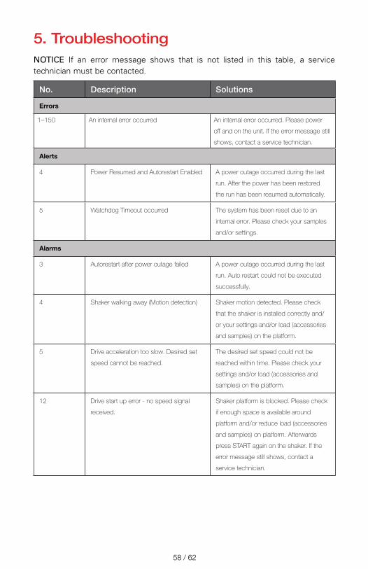
5. TroubleshootingNOTICE If an error message shows that is not listed in this table, a service technician must be contacted.
No. Description Solutions
Errors
1–150 An internal error occurred An internal error occurred. Please power
off and on the unit. If the error message still
shows, contact a service technician.
Alerts
4 Power Resumed and Autorestart Enabled A power outage occurred during the last
run. After the power has been restored
the run has been resumed automatically.
5 Watchdog Timeout occurred The system has been reset due to an
internal error. Please check your samples
and/or settings.
Alarms
3 Autorestart after power outage failed A power outage occurred during the last
run. Auto restart could not be executed
successfully.
4 Shaker walking away (Motion detection) Shaker motion detected. Please check
that the shaker is installed correctly and/
or your settings and/or load (accessories
and samples) on the platform.
5 Drive acceleration too slow. Desired set
speed cannot be reached.
The desired set speed could not be
reached within time. Please check your
settings and/or load (accessories and
samples) on the platform.
12 Drive start up error - no speed signal
received.
Shaker platform is blocked. Please check
if enough space is available around
platform and/or reduce load (accessories
and samples) on platform. Afterwards
press START again on the shaker. If the
error message still shows, contact a
service technician.

59 / 62
No. Description Solutions
24 Speed measurement error during a run. Abnormal speed change detected.
Please check load (accessories and
samples) and/or clamps on the shaker
platform. Afterwards press START again
on the shaker. If the error message still
shows, contact a service technician.
Speed comparison failed. Shaker platform has been blocked during
run. Please check if enough space is
available around platform and/or reduce
load (accessories and samples) on the
platform. Afterwards press START again
on the shaker. If the error message still
shows, contact a service technician.
26 Speed measurement detected
unexpected standstill during run.
Make sure that enough space is available
around the platform and/or reduce
load (accessories and samples) on the
platform.
Make sure that the fuse on the back of
the shaker has not tripped (“Fuse” on
page 20).
Afterwards press START again on the
shaker. If the error message still shows,
contact a service technician.
82 Motor current measurement detects
overload.
Motor overcurrent detected. Do not load
or unload platform while running. Reduce
speed or adjust load (accessories and
samples) on platform.
83 Motor current measurement out of
boundaries.
Motor overcurrent detected. Do not load
or unload platform while running. Reduce
speed or adjust load (accessories and
samples) on platform.
Table 11: Troubleshooting

Index
AAccessories 13, 41Alarms 30Alerts 30Autoclaving 56Auto Restart 32
BBrightness 32
CCare 52Charts 40Clamps 14Cleaning 54Connections 20Controls 30
DDate 32Decontamination 55Directives 18Disinfection 55Display 32Disposal 57Dual Stack 43
EEthernet 20Event Log 38
FFiles and Info 33Fuse 20
HHighest Speed 49
IInspection of Accessories 53Intended Use 6Items Supplied 21
LLanguage 32Leveling 23Loading 48Location 22
MMains Connection 20Maintenance 52Menu Bar Customization 32Metal Parts 54Microplate / Deepwell-Plate 47
NNormal Use 48, 49
OOperation 28Orbit Calculator 31
PPlastic Parts 54Platform Installation 41Platforms 13Product Overview 19Programs 33
RRegion 32
SSafe Speed 49Service 57Settings 30Shipping 27, 57Signal Words and Symbols 6Sleep Mode 33Snooze Timeout 30Speed Setpoint 30Standards 18Startup 24Storage 27Symbols used in the Instruction Manual 7
TTechnical Data 11Technical Specifications 11Test Tube Rack Clamp 46Test Tube Racks 16Time 32Time Mode 32Transporting 23Troubleshooting 58
UUnit Name 32Universal Platforms 42Unpacking 21USB 20User Interface 28
VVolume 30

en
thermofisher�com/shaker
© 2019 Thermo Fisher Scientific Inc. All rights reserved.
All trademarks are the property of Thermo Fisher Scientific Inc. and its subsidiaries unless otherwise indicated. Not all products are available in all countries. Please consult your local sales representative for details.
Shown pictures within the manual are examples and may differ considering the set parameters and language.
Australia +61 39757 4300
Austria +43 1 801 40 0
Belgium +32 53 73 42 41
China +800 810 5118 or +400 650 5118
France +33 2 2803 2180
Germany national toll free 0800 1 536 376
Germany international +49 6184 90 6000
India +91 22 6716 2200
Italy +39 02 95059 552
Japan +81 3 5826 1616
Netherlands +31 76 579 55 55
New Zealand +64 9 980 6700
Nordic/Baltic/CIS countries +358 10 329 2200
Russia +7 812 703 42 15
Spain/Portugal +34 93 223 09 18
Switzerland +41 44 454 12 12
UK/Ireland +44 870 609 9203
USA/Canada +1 866 984 3766
Other Asian Countries +852 2885 4613
Countries not listed +49 6184 90 6000
70900190 is the original instruction manual. This instruction manual is a translation of the original instruction manual.
Thermo Scientific Solaris 2000
Thermo Scientific Solaris 4000
Manufactured for
Thermo Electron LED GmbH
Zweigniederlassung Osterode
Am Kalkberg, 37520 Osterode am Harz
Germany
Made in USA


