12 · Thin Flexible Printed Circuit Supporting Transmission Rate from 1 to 10 Gbps FEATURED TOPIC 1. Introduction Recently, there has been a growing need for high- speed transmission in the field of electronic devices. And the transmission speeds of interface and mobile communication standards have been rapidly increasing. As shown in Fig. 1, the Sumitomo Electric Group has been developing products to meet the need for high-speed communication such as optical fibers, co-axial cables and FFCs. In tablet PCs and mobile phones, the demand for shorter transmission paths and lower profiles is increasing. In some fields, flexible printed circuits (FPCs) are beginning to be used as a means of high-speed wiring. We have developed an FPC for antennas that conforms to USB 3.0, one of the high-speed interface standards, and the Fourth-Generation Mobile Communication Standard. The details are described in the following sections. 2. Outline of High-Frequency FPCs Figure 2 illustrates the layer construction of a general FPC. A conductor circuit is formed on the base material made of insulating film. The created conductor circuit is coated with a material called “a cover lay,” which is an insulating film integrated with adhesive to protect the circuit or insulate it from another circuit. In general, an FPC with this configuration uses a polyimide film for the base material, and a polyimide film and epoxy adhesive for the cover lay. In case of a multi-layer circuit board, two FPCs are glued together with inter- layer adhesive (usually epoxy-based). Figure 3 shows the dielectric characteristics of different types of insulators. Common polyimide films, having superior dielectric characteristics compared to FR-4, which is used for rigid plates, are suitable for high-frequency applications. Thin Flexible Printed Circuit Supporting Transmission Rate from 1 to 10 Gbps Satoshi KIYA*, Katsuya MORIZANE, Yoshifumi UCHITA and Masahiko KOUCHI ---------------------------------------------------------------------------------------------------------------------------------------------------------------------------------------------------------------------------------------------------------- Due to the increasing demand for high speed communication in electronic equipment, rapid improvement is observed in data transmission rate through interface and wireless communication device. Particularly in the mobile device such as mobile phone and tablet PC, thinner and lighter FPC is required. In such high speed transmission field, flexible printed circuit (FPC) has been applied in place of co-axial cable. From this kind of circumstance we have started the development of high speed FPC. We have verified the transmission performance of the in-house developed FPC supporting USB 3.0 and 4G-antenna by optimizing FPC structure and material, thereby demonstrate the application possibility of the FPC in the high speed transmission field. ---------------------------------------------------------------------------------------------------------------------------------------------------------------------------------------------------------------------------------------------------------- Keywords: flexible printed circuits (FPC), high speed transmission, high frequency, low dielectric Transmission Distance・ Mounting Density(Small Pitch) Electrical Property ・Transmission Speed (bps/Lane) 1m 10m 1G 10M 10G 10cm 100M Small Size・ Mobile (~P0.4mm) Internal Wiring (P0.4~P1.0mm) Optical Transmission Band Impedance Matching Lower Loss Smaller Skew Shield Differential Transmission UTP (Unshielded Twist Pair Cable) STP (Shielded Twist Pair Cable) External Wiring (P1.0mm~) Impedance Matched FPC MFCX(Micro Flex Coaxial Cable) (AWG40~46) FFC for High Frequency ( AWG38) Miniature Twinax (AWG40) HCD-EXFFC (AWG34) LVCX (0.25~0.8DS) Normal FFC Shielded FPC Twinax、STP (AWG32~38) ・ Thicker Dia. ・ Multi Core ・ Multi Shield ・ Impedance Matching ・ Shield Discrete、 Ribbon Cable ・ Conventional Use・ Cheap Twinax、STP (AWG24~32) Normal FPC Shielded FFC UTP、 Parallel 2 Core ・ Differential Transmission Developed FPC Metal(Electro) Transmission Band Multilayer Single Side Multilayer (Double Side×2) Double Side Flexible Multilayer ••• Coverlay (PI) ••• Copper Foil ••• Copper Plating ••• Multilayer Adhesive ••• Base Film (PI) Fig. 1. Matrix of the Lengths of Wiring Inside and Outside Devices, and the Transmission Characteristics Fig. 2. Layer Configurations of General FPCs (One-sided, Double-sided, and Multi-layered)
Transcript
12 · Thin Flexible Printed Circuit Supporting Transmission Rate from 1 to 10 Gbps
FEATURED TOPIC
1. Introduction
Recently, there has been a growing need for high-speed transmission in the field of electronic devices. And the transmission speeds of interface and mobile communication standards have been rapidly increasing.
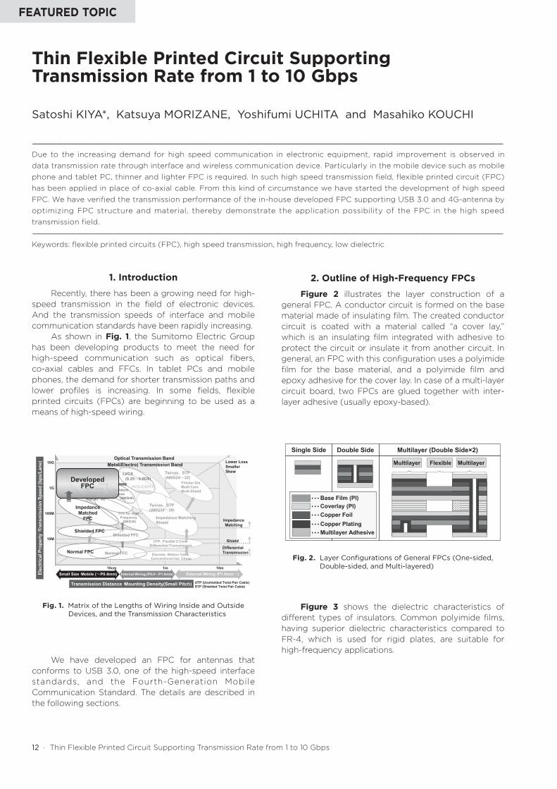
As shown in Fig. 1, the Sumitomo Electric Group has been developing products to meet the need for high-speed communication such as optical fibers, co-axial cables and FFCs. In tablet PCs and mobile phones, the demand for shorter transmission paths and lower profiles is increasing. In some fields, flexible printed circuits (FPCs) are beginning to be used as a means of high-speed wiring.
We have developed an FPC for antennas that conforms to USB 3.0, one of the high-speed interface standards, and the Fourth-Generation Mobile Communication Standard. The details are described in the following sections.
2. Outline of High-Frequency FPCs
Figure 2 illustrates the layer construction of a general FPC. A conductor circuit is formed on the base material made of insulating film. The created conductor circuit is coated with a material called “a cover lay,” which is an insulating film integrated with adhesive to protect the circuit or insulate it from another circuit. In general, an FPC with this configuration uses a polyimide film for the base material, and a polyimide film and epoxy adhesive for the cover lay. In case of a multi-layer circuit board, two FPCs are glued together with inter-layer adhesive (usually epoxy-based).
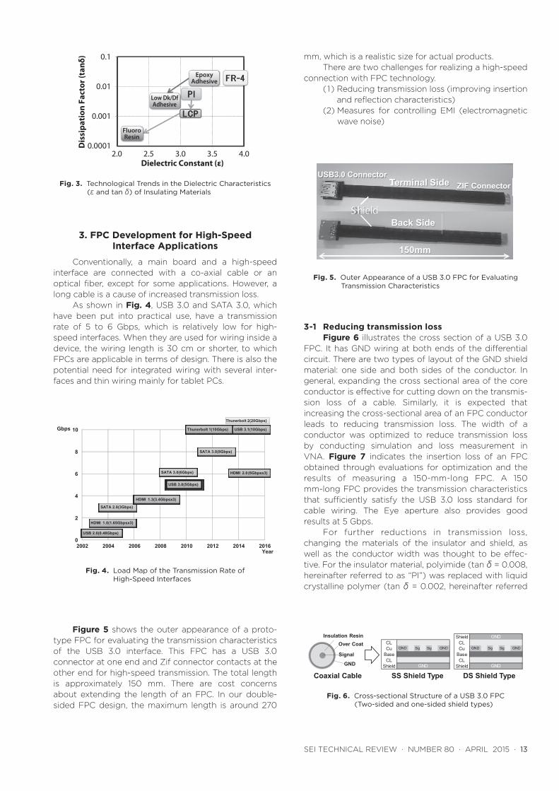
Figure 3 shows the dielectric characteristics of different types of insulators. Common polyimide films, having superior dielectric characteristics compared to FR-4, which is used for rigid plates, are suitable for high-frequency applications.
Thin Flexible Printed Circuit Supporting Transmission Rate from 1 to 10 Gbps
Satoshi KIYA*, Katsuya MORIZANE, Yoshifumi UCHITA and Masahiko KOUCHI
----------------------------------------------------------------------------------------------------------------------------------------------------------------------------------------------------------------------------------------------------------Due to the increasing demand for high speed communication in electronic equipment, rapid improvement is observed in data transmission rate through interface and wireless communication device. Particularly in the mobile device such as mobile phone and tablet PC, thinner and lighter FPC is required. In such high speed transmission field, flexible printed circuit (FPC) has been applied in place of co-axial cable. From this kind of circumstance we have started the development of high speed FPC. We have verified the transmission performance of the in-house developed FPC supporting USB 3.0 and 4G-antenna by optimizing FPC structure and material, thereby demonstrate the application possibility of the FPC in the high speed transmission field.
----------------------------------------------------------------------------------------------------------------------------------------------------------------------------------------------------------------------------------------------------------Keywords: flexible printed circuits (FPC), high speed transmission, high frequency, low dielectric
Fig. 1. Matrix of the Lengths of Wiring Inside and Outside Devices, and the Transmission Characteristics
Fig. 2. Layer Configurations of General FPCs (One-sided, Double-sided, and Multi-layered)
SEI TECHNICAL REVIEW · NUMBER 80 · APRIL 2015 · 13
3. FPC Development for High-Speed Interface Applications
Conventionally, a main board and a high-speed interface are connected with a co-axial cable or an optical fiber, except for some applications. However, a long cable is a cause of increased transmission loss.
As shown in Fig. 4, USB 3.0 and SATA 3.0, which have been put into practical use, have a transmission rate of 5 to 6 Gbps, which is relatively low for high-speed interfaces. When they are used for wiring inside a device, the wiring length is 30 cm or shorter, to which FPCs are applicable in terms of design. There is also the potential need for integrated wiring with several inter-faces and thin wiring mainly for tablet PCs.
Figure 5 shows the outer appearance of a proto-type FPC for evaluating the transmission characteristics of the USB 3.0 interface. This FPC has a USB 3.0 connector at one end and Zif connector contacts at the other end for high-speed transmission. The total length is approximately 150 mm. There are cost concerns about extending the length of an FPC. In our double-sided FPC design, the maximum length is around 270
mm, which is a realistic size for actual products.There are two challenges for realizing a high-speed
connection with FPC technology.(1) Reducing transmission loss (improving insertion
and reflection characteristics)(2) Measures for controlling EMI (electromagnetic
wave noise)
3-1 Reducing transmission lossFigure 6 illustrates the cross section of a USB 3.0
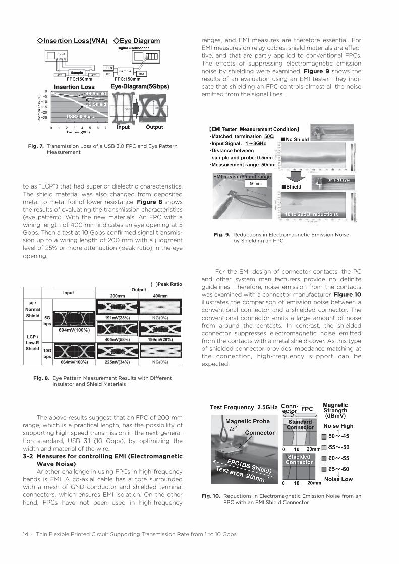
FPC. It has GND wiring at both ends of the differential circuit. There are two types of layout of the GND shield material: one side and both sides of the conductor. In general, expanding the cross sectional area of the core conductor is effective for cutting down on the transmis-sion loss of a cable. Similarly, it is expected that increasing the cross-sectional area of an FPC conductor leads to reducing transmission loss. The width of a conductor was optimized to reduce transmission loss by conducting simulation and loss measurement in VNA. Figure 7 indicates the insertion loss of an FPC obtained through evaluations for optimization and the results of measuring a 150-mm-long FPC. A 150 mm-long FPC provides the transmission characteristics that sufficiently satisfy the USB 3.0 loss standard for cable wiring. The Eye aperture also provides good results at 5 Gbps.
For further reductions in transmission loss, changing the materials of the insulator and shield, as well as the conductor width was thought to be effec-tive. For the insulator material, polyimide (tan δ = 0.008, hereinafter referred to as “PI”) was replaced with liquid crystalline polymer (tan δ = 0.002, hereinafter referred
Dis
sipa
tion
Fac
tor (
tanδ
) 0.1
0.01
0.001
0.00012.0 2.5 3.0 3.5 4.0
Dielectric Constant (ε)
EpoxyAdhesive
FluoroResin
Low Dk/DfAdhesive
0
2
4
6
8
10
2002 2004 2006 2008 2010 2012 2014 2016
Gbps
Year
USB 2.0(0.48Gbps)
SATA 2.0(3Gbps)
HDMI 1.3(3.4Gbpsx3)
USB 3.0(5Gbps)
SATA 3.0(6Gbps)
USB 3.1(10Gbps)
SATA 3.0(8Gbps)
HDMI 2.0(6Gbpsx3)
HDMI 1.0(1.65Gbpsx3)
Thunerbolt 1(10Gbps)
Thunerbolt 2(20Gbps)
Fig. 3. Technological Trends in the Dielectric Characteristics (ε and tan δ) of Insulating Materials
Fig. 4. Load Map of the Transmission Rate of High-Speed Interfaces
Terminal Side
Back Side
TUSB3.0 Connector
ZIF Connector
Shield
150mm
Coaxial Cable
Insulation Resin
Signal
GND
Over Coat CLCu Sig Sig
BaseCL
Shield GND
GND GND
DS Shield TypeSS Shield Type
ShieldCLCu Sig Sig
BaseCL
Shield GND
GND
GND GND
Fig. 5. Outer Appearance of a USB 3.0 FPC for Evaluating Transmission Characteristics
Fig. 6. Cross-sectional Structure of a USB 3.0 FPC (Two-sided and one-sided shield types)
14 · Thin Flexible Printed Circuit Supporting Transmission Rate from 1 to 10 Gbps
to as “LCP”) that had superior dielectric characteristics. The shield material was also changed from deposited metal to metal foil of lower resistance. Figure 8 shows the results of evaluating the transmission characteristics (eye pattern). With the new materials, An FPC with a wiring length of 400 mm indicates an eye opening at 5 Gbps. Then a test at 10 Gbps confirmed signal transmis-sion up to a wiring length of 200 mm with a judgment level of 25% or more attenuation (peak ratio) in the eye opening.
The above results suggest that an FPC of 200 mm range, which is a practical length, has the possibility of supporting high-speed transmission in the next-genera-tion standard, USB 3.1 (10 Gbps), by optimizing the width and material of the wire.3-2 Measures for controlling EMI (Electromagnetic
Wave Noise)Another challenge in using FPCs in high-frequency
bands is EMI. A co-axial cable has a core surrounded with a mesh of GND conductor and shielded terminal connectors, which ensures EMI isolation. On the other hand, FPCs have not been used in high-frequency
ranges, and EMI measures are therefore essential. For EMI measures on relay cables, shield materials are effec-tive, and that are partly applied to conventional FPCs. The effects of suppressing electromagnetic emission noise by shielding were examined. Figure 9 shows the results of an evaluation using an EMI tester. They indi-cate that shielding an FPC controls almost all the noise emitted from the signal lines.
For the EMI design of connector contacts, the PC and other system manufacturers provide no definite guidelines. Therefore, noise emission from the contacts was examined with a connector manufacturer. Figure 10 illustrates the comparison of emission noise between a conventional connector and a shielded connector. The conventional connector emits a large amount of noise from around the contacts. In contrast, the shielded connector suppresses electromagnetic noise emitted from the contacts with a metal shield cover. As this type of shielded connector provides impedance matching at the connection, high-frequency support can be expected.
200mm 400mm
PI /NormalShield 191mV(28%) NG(0%)
405mV(58%) 199mV(29%)
10Gbps
664mV(100%) 225mV(34%) NG(0%)
Input
5Gbps
LCP /Low-RShield
Output
694mV(100%)
( )Peak Ratio
Fig. 7. Transmission Loss of a USB 3.0 FPC and Eye Pattern Measurement
Fig. 8. Eye Pattern Measurement Results with Different Insulator and Shield Materials
Fig. 9. Reductions in Electromagnetic Emission Noise by Shielding an FPC
Fig. 10. Reductions in Electromagnetic Emission Noise from an FPC with an EMI Shield Connector
SEI TECHNICAL REVIEW · NUMBER 80 · APRIL 2015 · 15
4. FPCs for Mobile Device Antennas
In the field of mobile devices, the mainstay prod-ucts have been changing, from flip mobile phones to smartphones in recent years. The communication stan-dard has been progressing to higher speeds from 3rd Generation (3G) to 4th Generation (LTE). Following this trend, there is a growing need for high-frequency, and high-transmission speed supports in electronic compo-nents. As smartphones require batteries with larger capacities compared to flip mobile phones, space saving is also required. Figure 11 summarizes the internal struc-ture of a smartphone. In conventional design, the elec-tromagnetic signal received from the antenna FPC is transmitted to the main board through a co-axial cable. However, in mobile devices, as the length of the trans-mission to the main board is 15 cm or shorter in most cases, the co-axial cable can be replaced with an FPC safely in terms of design. We have developed an antenna FPC integrated with a multi-layer board FPC that replaces the co-axial cable in order to respond to the need for high-speed transmission and space saving.
Figure 12 shows the cross section of a co-axial cable and an integrated antenna FPC. The co-axial cable has a core, which transmits a signal, is surrounded with a low-dielectric fluoroplastic and an outer layer that serves as a GND conductor. The integrated antenna FPC has a similar structure. The outer layer is a GND conductor and the transmission circuit is at the center, which results in a reduction in thickness by approxi-mately 65%.
Conventional multi-layer FPCs use polyimide or epoxy inter-layer adhesive. However, these materials have large dielectric loss tangents, which is inappro-priate for high-speed transmission. Reducing transmis-sion loss has been the biggest challenge for responding to the needs of users. The integrated antenna FPC developed for transmission loss reduction uses low-dielectric materials for the base and inter-layer adhesive to support high transmission speeds. The flexible circuit arrangement, one of the features of an FPC, enables optimization for high-speed transmission with small transmission loss. Figure 13 compares the transmission loss of a co-axial cable and an integrated antenna FPC
made of LCP. The transmission loss of the integrated antenna FPC is -2.0 dB or smaller, which sufficiently supports the communication speed of the 4th Generation, satisfying the requirements of high-speed transmission. The integrated antenna FPC we devel-oped responds to the need for both high transmission speeds and space saving.
5. Conclusion
There is a growing requirement for high-speed transmission especially in the field of communication. In-vehicle applications use high-speed devices such as millimeter wave antennas. The potential need for high-frequency boards is starting to expand. Based on the above results, we have started research on next-genera-tion high-speed FPCs and will accelerate technological development with an eye toward horizontal expansion to new fields.
Fig. 11. Summary of the Internal Structure of a Smartphone
Fig. 12. Cross Section of an Integrated Antenna FPC
Fig. 13. Comparison in Transmission Loss of Co-axial Cables and an Integrated Antenna FPC
16 · Thin Flexible Printed Circuit Supporting Transmission Rate from 1 to 10 Gbps