Third-harmonic generation ~THG! microscopy haseen demonstrated recently in biological speci-ens.1,2 The THG imaging of transparent nonbio-
logical objects like glass and liquid crystals have alsobeen reported.3–6 Current activities in THG imag-ing seem to have been stimulated by Tsang7 whofound that with high-intensity focused-beam excita-tion, the normally weak THG process becomes strongby several orders of magnitude at an air–dielectricinterface. Furthermore, the said THG process isfree from the constraint imposed by the phase-matching condition that normally renders the opticalgeneration of higher harmonic signals difficult to re-alize in bulk media.
One distinct advantage of THG imaging over fluo-rescence imaging is that it can proceed without theneed to label the biological sample with appropriateprobes. The refractive-index inhomogeneities in thespecimen form the interfaces in which a sufficientlystrong THG signal can be generated. Site-specificfluorescence staining is difficult to accomplish in op-
The authors are with the National Institute of Physics, Univer-sity of the Philippines, Diliman, Quezon City 1101, Philippines.C. Saloma’s e-mail address is [email protected].
Received 10 April 2000; revised manuscript received 12 June2000.
tically thick biological specimens like the midgesta-tion and perenatal wholemount mouse embryos.8Biological specimens also seem to be quite robustagainst THG excitation.1,2 In contrast, fluorescentspecimens are quite sensitive to photobleaching, par-ticularly with focused-beam excitation.
Here we analyze the performance of THG imagingin highly scattering media, which is an issue that is ofconsiderable importance in medicine and biology inwhich the capability to observe organs inside an op-tically thick specimen can lead to great simplifica-tions in the sample preparation process. Forexample, site-specific fluorescence imaging has neverbeen performed with wholemount mouse embryos inthe advanced state of gestation because the interven-ing skin tissues is highly scattering and impermeableto probe labeling by diffusion.8 With such speci-mens, the tedious job of physical slicing by microtomeor vibrotome, becomes compulsory. Physical slicingis an invasive process that could result in unwanteddamage to tissues and organs. Specifically, we de-termine the characteristics of the three-dimensional~3D! point-spread function ~PSF! of the THG micro-cope under various scattering conditions. To ournowledge such a study has never been reported be-ore.
In THG imaging the specimen is excited by aulsed focused beam of wavelength le and produces a
THG signal of wavelength lg 5 ley3. The THG sig-nal, which is proportional to the third power of theexcitation intensity, is produced only from interfaces
1 October 2000 y Vol. 39, No. 28 y APPLIED OPTICS 5187
t
s
sf
t
uat
tL
5
in and around the excitation beam focus. The highlylocalized nature of the THG signal generation per-mits the realization of optical sectioning even with alarge-area photodetector just like in a two-photon ex-citation fluorescence ~2PF! microscope.9,10
Unlike fluorescence signals that have finite relax-ation times, the generation of the THG signal is es-sentially instantaneous, and the THG excitationbeam can be delivered at faster repetition rates, al-lowing the use of higher peak intensities without ex-ceeding the acceptable average intensity levels toprevent specimen damage. Recent reports1–3 alsoindicated that the THG conversion efficiency is suf-ficiently high to permit the use of moderate numeri-cal apertures ~NA! for the focusing lens. The saidcapabilities are particularly critical during imagingthrough thick optical samples in which objectiveswith long working distances ~in the millimeter range!are needed. Such objectives are difficult and veryexpensive to manufacture at high NA values.
Our presentation proceeds as follows: In Section2 we describe the procedure used to calculate thetransverse and axial PSF’s of the THG microscope.We present the results of the numerical experimentsin Section 3 and subsequently analyzed them in Sec-tion 4.
2. Model
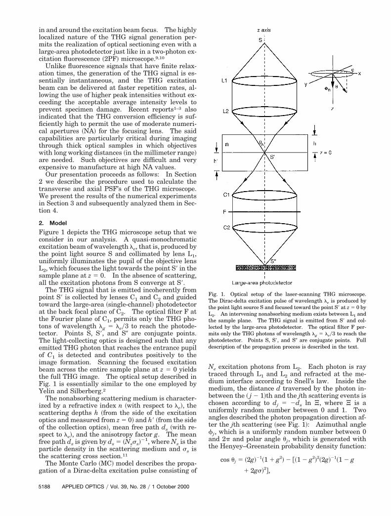
Figure 1 depicts the THG microscope setup that weconsider in our analysis. A quasi-monochromaticexcitation beam of wavelength le, that is, produced bythe point light source S and collimated by lens L1,uniformly illuminates the pupil of the objective lensL2, which focuses the light towards the point S9 in thesample plane at z 5 0. In the absence of scattering,all the excitation photons from S converge at S9.
The THG signal that is emitted incoherently frompoint S9 is collected by lenses C1 and C2 and guidedtoward the large-area ~single-channel! photodetectorat the back focal plane of C2. The optical filter F atthe Fourier plane of C1, permits only the THG pho-ons of wavelength lg 5 ley3 to reach the photode-
tector. Points S, S9, and S0 are conjugate points.The light-collecting optics is designed such that anyemitted THG photon that reaches the entrance pupilof C1 is detected and contributes positively to theimage formation. Scanning the focused excitationbeam across the entire sample plane at z 5 0 yieldsthe full THG image. The optical setup described inFig. 1 is essentially similar to the one employed byYelin and Silberberg.2
The nonabsorbing scattering medium is character-ized by a refractive index n ~with respect to le!, thecattering depths h ~from the side of the excitation
optics and measured from z 5 0! and h9 ~from the sideof the collection optics!, mean free path ds ~with re-pect to le!, and the anisotropy factor g. The meanree path ds is given by ds 5 ~Nsss!
21, where Ns is theparticle density in the scattering medium and ss ishe scattering cross section.11
The Monte Carlo ~MC! model describes the propa-gation of a Dirac-delta excitation pulse consisting of
188 APPLIED OPTICS y Vol. 39, No. 28 y 1 October 2000
Ne excitation photons from L2. Each photon is raytraced through L1 and L2 and refracted at the me-dium interface according to Snell’s law. Inside themedium, the distance d traversed by the photon in-between the ~ j 2 1!th and the jth scattering events ischosen according to dj 5 2ds ln J, where J is a
niformly random number between 0 and 1. Twongles described the photon propagation direction af-er the jth scattering ~see Fig. 1!: Azimuthal angle
fj, which is a uniformly random number between 0and 2p and polar angle uj, which is generated withthe Henyey–Greenstein probability density function:
cos uj 5 ~2g!21~1 1 g2! 2 @~1 2 g2!2~2g!21~1 2 g
1 2gs!2#,
Fig. 1. Optical setup of the laser-scanning THG microscope.The Dirac-delta excitation pulse of wavelength le is produced byhe point light source S and focused toward the point S9 at z 5 0 by2. An intervening nonabsorbing medium exists between L1 and
the sample plane. The THG signal is emitted from S9 and col-lected by the large-area photodetector. The optical filter F per-mits only the THG photons of wavelength lg 5 ley3 to reach thephotodetector. Points S, S9, and S0 are conjugate points. Fulldescription of the propagation process is described in the text.
a
m
l
pftb
l
tw
where s is a uniformly random number between 0nd 1 and 0 # g 5 ^cos uj& # 1. Subsequent gener-
ations of dj9s, fj9s, and uj9s, allow the excitation pho-ton to move toward the sample plane. The randomnumbers J and s are generated independently withthe linear congruential method.
Isotropic scattering ~e.g., Rayleigh scattering! cor-responds to g ' 0, whereas extreme anisotropic ~for-ward! scattering ~e.g., by particles with sizeparameter p 5 2payl .. 1, where a is the particleradius! corresponds to g ' 1. Every calculation ofthe 3D distribution of the THG excitation beam in thescattering medium involves the release of Ne photonsfrom S. Each photon is individually traced by theMC method inside the scattering medium. Multiplescattering causes the paths of the Ne photons to varyfrom their unscattered optical paths, and as a result,the number that could reach the z 5 0 plane is lessthan Ne. The tracing of an excitation photon isabandoned if after 50 scattering events it is unable toreach the z 5 0 plane. Additional details regardingthe MC method have been reported.9,10
The MC simulation does not consider the wavenature of light and therefore could not account fordiffraction and interference effects. In the absenceof scattering, it yields the focal distributions for theexcitation beam that are consistent with Gaussianoptics L2.12 The MC simulation is reliable in ac-counting for the distribution of the backscattered ex-citation light and the reduction that is caused byscattering to the excitation ~peak! power that is de-livered at the focal region of L2. Its predictions havebeen utilized effectively for enhancing images thatare produced by a 2PF microscope in highly scatter-ing media13 as well as for determining the appropri-ate detector pinhole size in single-photon excitationconfocal fluorescence microscopy in wholemountmouse embryos.8
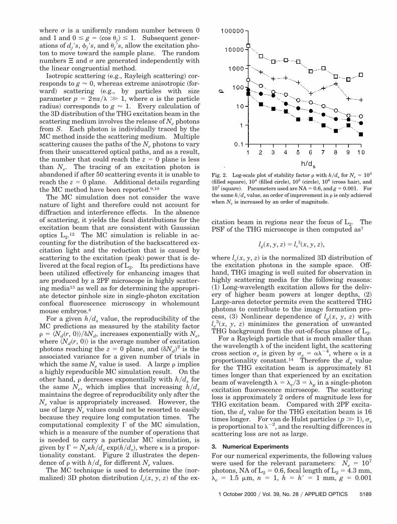
For a given hyds value, the reproducibility of theMC predictions as measured by the stability factorr 5 ^Nd~r, 0!&ydNd, increases exponentially with Ne,where ^Nd~r, 0!& is the average number of excitationphotons reaching the z 5 0 plane, and ~dNd!2 is theassociated variance for a given number of trials inwhich the same Ne value is used. A large r impliesa highly reproducible MC simulation result. On theother hand, r decreases exponentially with hyds forthe same Ne, which implies that increasing hydsmaintains the degree of reproducibility only after theNe value is appropriately increased. However, theuse of large Ne values could not be resorted to easilybecause they require long computation times. Thecomputational complexity G of the MC simulation,which is a measure of the number of operations thatis needed to carry a particular MC simulation, isgiven by G 5 Nekhyds exp~hyds!, where k is a propor-tionality constant. Figure 2 illustrates the depen-dence of r with hyds for different Ne values.
The MC technique is used to determine the ~nor-alized! 3D photon distribution le~x, y, z! of the ex-
citation beam in regions near the focus of L2. ThePSF of the THG microscope is then computed as7
lg~x, y, z! 5 le3~x, y, z!,
where le~x, y, z! is the normalized 3D distribution ofthe excitation photons in the sample space. Off-hand, THG imaging is well suited for observation inhighly scattering media for the following reasons:~1! Long-wavelength excitation allows for the deliv-ery of higher beam powers at longer depths, ~2!Large-area detector permits even the scattered THGphotons to contribute to the image formation pro-cess, ~3! Nonlinear dependence of lg~x, y, z! withe3~x, y, z! minimizes the generation of unwanted
THG background from the out-of-focus planes of L2.For a Rayleigh particle that is much smaller than
the wavelength l of the incident light, the scatteringcross section ss is given by ss 5 al24, where a is a
roportionality constant.14 Therefore the ds valueor the THG excitation beam is approximately 81imes longer than that experienced by an excitationeam of wavelength l 5 ley3 5 lg in a single-photon
excitation fluorescence microscope. The scatteringloss is approximately 2 orders of magnitude less forTHG excitation beam. Compared with 2PF excita-tion, the ds value for the THG excitation beam is 16times longer. For van de Hulst particles ~p .. 1!, ssis proportional to l22, and the resulting differences inscattering loss are not as large.
3. Numerical Experiments
For our numerical experiments, the following valueswere used for the relevant parameters: Ne 5 107
photons, NA of L2 5 0.6, focal length of L2 5 4.3 mm,e 5 1.5 mm, n 5 1, h 5 h9 5 1 mm, g 5 0.001
Fig. 2. Log-scale plot of stability factor r with hyds for Ne 5 103
~filled square!, 104 ~filled circle!, 105 ~circle!, 106 ~cross hair!, and107 ~square!. Parameters used are NA 5 0.6, and g 5 0.001. Forhe same hyds value, an order of improvement in r is only achievedhen Ne is increased by an order of magnitude.
1 October 2000 y Vol. 39, No. 28 y APPLIED OPTICS 5189
t
i
w
eg5l
4g
e
tcob
~
t
~
i
5
~isotropic scattering!, and g 5 0.9 ~anisotropic scat-ering!. The le and NA values are the same as the
ones cited by Yelin and Silberberg.2 Lenses L1, L2,L3, and L4 are assumed to be identical. The numer-ical experiments were performed with 633-Mhz DECAlpha computers. Because of computational limita-tions, the use of larger Ne values was not possible.
Figures 3~a!–3~d! present examples of the time-ntegrated 3D distributions le~r, z! of THG excitation
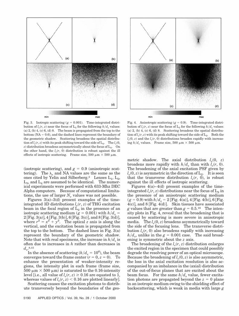
beam in the focal region of L2 in the presence of anisotropic scattering medium ~g 5 0.001! with hyds 52 @Fig. 3~a!#, 4 @Fig. 3~b!#, 6 @Fig. 3~c!#, and 8 @Fig. 3~d!#,
here r2 5 x2 1 y2. The optical z axis is along thevertical, and the excitation beam is propagated fromthe top to the bottom. The dashed lines in Fig. 3~a!represent the boundary of the geometric shadow.Note that with real specimens, the increase in hyds isoften due to increases in h rather than decreases inds.8,15
In the absence of scattering ~hyds 5 106!, the beamconverges toward the frame center ~r 5 0, z 5 0!. Tonhance the presentation of weaker-intensity re-ions, the intensity plot in each frame ~frame size,00 mm 3 500 mm! is saturated to the 0.16-intensityevel @i.e., all value of le~r, z! $ 0.16 are equated to 1,
whereas values of le~r, z! , 0.16 are plotted linearly#.Scattering causes the excitation photons to distrib-
ute transversely beyond the boundaries of the geo-
Fig. 3. Isotropic scattering ~g 5 0.001!. Time-integrated distri-bution of le~r, z! near the focus of L2 for the following hyds values:a! 2, ~b! 4, ~c! 6, ~d! 8. The beam is propagated from the top to the
bottom ~NA 5 0.6!, and the dashed lines represent the boundary ofthe geometric shadow. Scattering broadens the spatial distribu-tion of le~r, z! with its peak shifting toward the side of L2. The le~0,z! distribution broadens asymmetrically about the focus of L2. Onhe other hand, the le~r, 0! distribution is robust against the ill
effects of isotropic scattering. Frame size, 500 mm 3 500 mm.
190 APPLIED OPTICS y Vol. 39, No. 28 y 1 October 2000
metric shadow. The axial distribution le~0, z!broadens more rapidly with hyds than with le~r, 0!.The broadening of the axial excitation PSF given byle~0, z! is asymmetric in the direction of L2. It is seenthat the transverse distribution le~r, 0!, is robustagainst the ill effects of isotropic scattering.
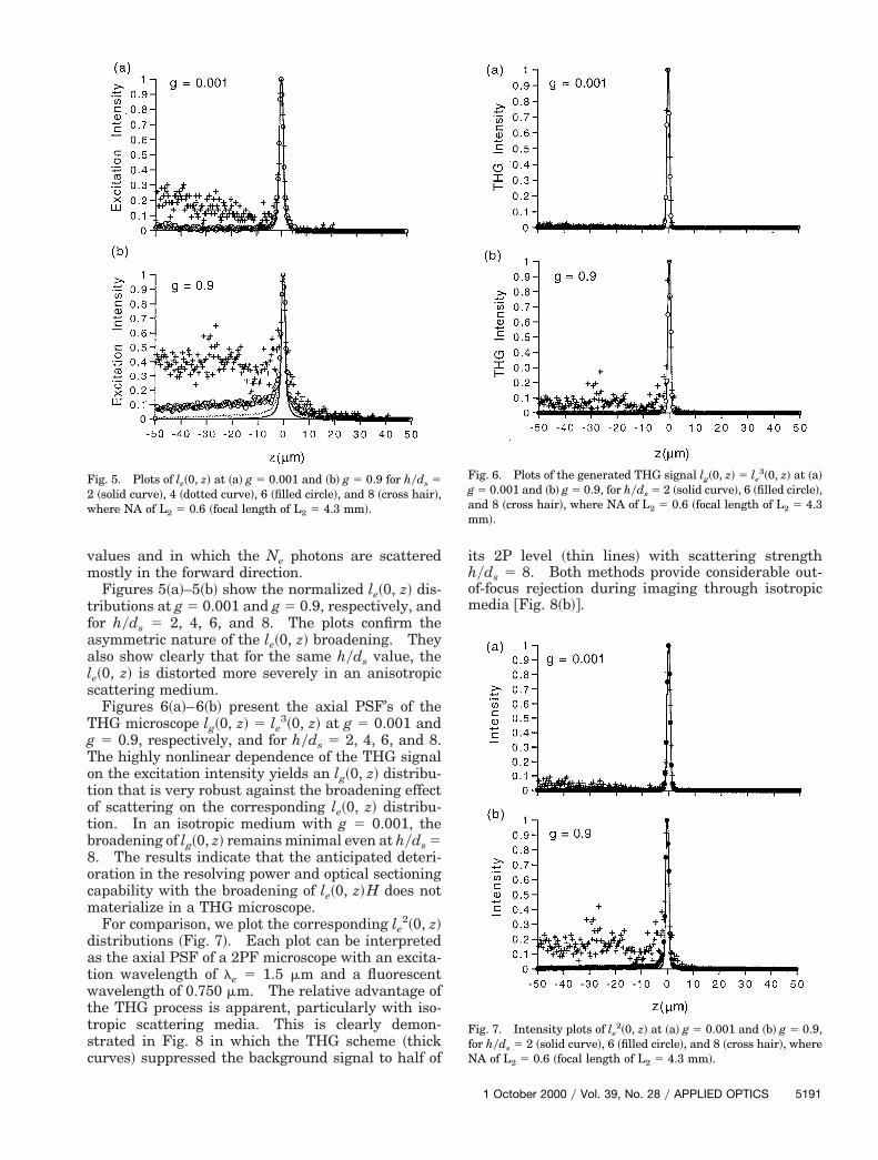
Figures 4~a!–4~d! present examples of the time-integrated le~r, z! distributions near the focus of L2 inthe presence of an anisotropic scattering medium~g 5 0.9! with hyds 5 2 @Fig. 4~a!#, 4 @Fig. 4~b!#, 6 @Fig.~c!#, and 8 @Fig. 4~d!#. Skin tissues have associatedvalues that are greater than g 5 0.5.16 The inten-
sity plots in Fig. 4, reveal that the broadening that iscaused by scattering is more severe in anisotropicmedia. The le~0, z! broadens asymmetrically towardthe side of the focusing lens. The transverse distri-bution le~r, 0! also broadens rapidly with increasinghyds, unlike in the g 5 0.001 case. The said broad-ning is symmetric about the z axis.The broadening of the le~r, z! distribution enlarges
the excited region in the specimen that could possiblydegrade the resolving power of an optical microscope.Because the broadening of le~0, z! is also asymmetric,he loss in the axial excitation resolution is also ac-ompanied by an imbalance in the ~axial! distributionf the out-of-focus planes that are excited about theeam focus. For the same hyds value, fewer excita-
tion photons are propagated beyond the z 5 0 planein an isotropic medium owing to the shielding effect ofbackscattering, which is weak in media with large g
Fig. 4. Anisotropic scattering ~g 5 0.9!. Time-integrated distri-bution of le~r, z! near the focus of L2 for the following hyds values:a! 2, ~b! 4, ~c! 6, ~d! 8. Scattering broadens the spatial distribu-
tion of le~r, z! with its peak shifting toward the side of L2. Both thele~0, z! and the le~r, 0! distributions broaden rapidly with increas-ng hyds values. Frame size, 500 mm 3 500 mm.
f
wtts
values and in which the Ne photons are scatteredmostly in the forward direction.
Figures 5~a!–5~b! show the normalized le~0, z! dis-tributions at g 5 0.001 and g 5 0.9, respectively, andor hyds 5 2, 4, 6, and 8. The plots confirm the
asymmetric nature of the le~0, z! broadening. Theyalso show clearly that for the same hyds value, thele~0, z! is distorted more severely in an anisotropicscattering medium.
Figures 6~a!–6~b! present the axial PSF’s of theTHG microscope lg~0, z! 5 le
3~0, z! at g 5 0.001 andg 5 0.9, respectively, and for hyds 5 2, 4, 6, and 8.The highly nonlinear dependence of the THG signalon the excitation intensity yields an lg~0, z! distribu-tion that is very robust against the broadening effectof scattering on the corresponding le~0, z! distribu-tion. In an isotropic medium with g 5 0.001, thebroadening of lg~0, z! remains minimal even at hyds 58. The results indicate that the anticipated deteri-oration in the resolving power and optical sectioningcapability with the broadening of le~0, z!H does notmaterialize in a THG microscope.
For comparison, we plot the corresponding le2~0, z!
distributions ~Fig. 7!. Each plot can be interpretedas the axial PSF of a 2PF microscope with an excita-tion wavelength of le 5 1.5 mm and a fluorescent
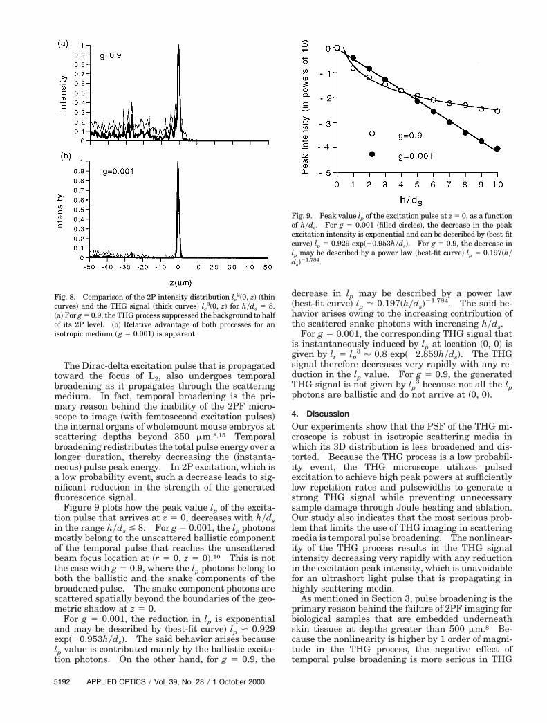
avelength of 0.750 mm. The relative advantage ofhe THG process is apparent, particularly with iso-ropic scattering media. This is clearly demon-trated in Fig. 8 in which the THG scheme ~thick
curves! suppressed the background signal to half of
its 2P level ~thin lines! with scattering strengthhyds 5 8. Both methods provide considerable out-of-focus rejection during imaging through isotropicmedia @Fig. 8~b!#.
Fig. 5. Plots of le~0, z! at ~a! g 5 0.001 and ~b! g 5 0.9 for hyds 52 ~solid curve!, 4 ~dotted curve!, 6 ~filled circle!, and 8 ~cross hair!,where NA of L2 5 0.6 ~focal length of L2 5 4.3 mm!.
Fig. 6. Plots of the generated THG signal lg~0, z! 5 le3~0, z! at ~a!
g 5 0.001 and ~b! g 5 0.9, for hyds 5 2 ~solid curve!, 6 ~filled circle!,and 8 ~cross hair!, where NA of L2 5 0.6 ~focal length of L2 5 4.3mm!.
Fig. 7. Intensity plots of le2~0, z! at ~a! g 5 0.001 and ~b! g 5 0.9,
for hyds 5 2 ~solid curve!, 6 ~filled circle!, and 8 ~cross hair!, whereNA of L2 5 0.6 ~focal length of L2 5 4.3 mm!.
1 October 2000 y Vol. 39, No. 28 y APPLIED OPTICS 5191
anfl
mob
bbsm
e
l
5
The Dirac-delta excitation pulse that is propagatedtoward the focus of L2, also undergoes temporalbroadening as it propagates through the scatteringmedium. In fact, temporal broadening is the pri-mary reason behind the inability of the 2PF micro-scope to image ~with femtosecond excitation pulses!the internal organs of wholemount mouse embryos atscattering depths beyond 350 mm.8,15 Temporalbroadening redistributes the total pulse energy over alonger duration, thereby decreasing the ~instanta-neous! pulse peak energy. In 2P excitation, which is
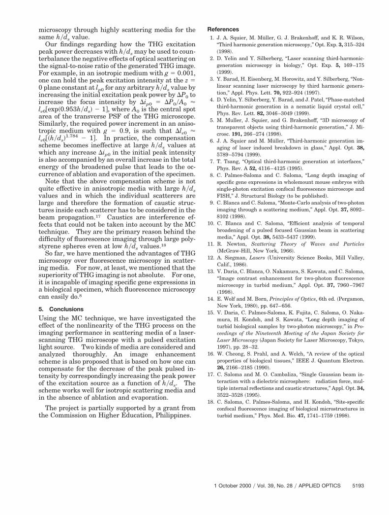
low probability event, such a decrease leads to sig-ificant reduction in the strength of the generateduorescence signal.Figure 9 plots how the peak value lp of the excita-
tion pulse that arrives at z 5 0, decreases with hydsin the range hyds # 8. For g 5 0.001, the lp photons
ostly belong to the unscattered ballistic componentf the temporal pulse that reaches the unscatteredeam focus location at ~r 5 0, z 5 0!.10 This is not
the case with g 5 0.9, where the lp photons belong tooth the ballistic and the snake components of theroadened pulse. The snake component photons arecattered spatially beyond the boundaries of the geo-etric shadow at z 5 0.For g 5 0.001, the reduction in lp is exponential
and may be described by ~best-fit curve! lp ' 0.929xp~20.953hyds!. The said behavior arises because
lp value is contributed mainly by the ballistic excita-tion photons. On the other hand, for g 5 0.9, the
Fig. 8. Comparison of the 2P intensity distribution le2~0, z! ~thin
curves! and the THG signal ~thick curves! le3~0, z! for hyds 5 8.
~a! For g 5 0.9, the THG process suppressed the background to halfof its 2P level. ~b! Relative advantage of both processes for anisotropic medium ~g 5 0.001! is apparent.
192 APPLIED OPTICS y Vol. 39, No. 28 y 1 October 2000
decrease in lp may be described by a power law~best-fit curve! lp ' 0.197~hyds!
21.784. The said be-havior arises owing to the increasing contribution ofthe scattered snake photons with increasing hyds.
For g 5 0.001, the corresponding THG signal thatis instantaneously induced by lp at location ~0, 0! isgiven by lt 5 lp
3 ' 0.8 exp~22.859hyds!. The THGsignal therefore decreases very rapidly with any re-duction in the lp value. For g 5 0.9, the generatedTHG signal is not given by lp
3 because not all the lpphotons are ballistic and do not arrive at ~0, 0!.
4. Discussion
Our experiments show that the PSF of the THG mi-croscope is robust in isotropic scattering media inwhich its 3D distribution is less broadened and dis-torted. Because the THG process is a low probabil-ity event, the THG microscope utilizes pulsedexcitation to achieve high peak powers at sufficientlylow repetition rates and pulsewidths to generate astrong THG signal while preventing unnecessarysample damage through Joule heating and ablation.Our study also indicates that the most serious prob-lem that limits the use of THG imaging in scatteringmedia is temporal pulse broadening. The nonlinear-ity of the THG process results in the THG signalintensity decreasing very rapidly with any reductionin the excitation peak intensity, which is unavoidablefor an ultrashort light pulse that is propagating inhighly scattering media.
As mentioned in Section 3, pulse broadening is theprimary reason behind the failure of 2PF imaging forbiological samples that are embedded underneathskin tissues at depths greater than 500 mm.8 Be-cause the nonlinearity is higher by 1 order of magni-tude in the THG process, the negative effect oftemporal pulse broadening is more serious in THG
Fig. 9. Peak value lp of the excitation pulse at z 5 0, as a functionof hyds. For g 5 0.001 ~filled circles!, the decrease in the peakexcitation intensity is exponential and can be described by ~best-fitcurve! lp 5 0.929 exp~20.953hyds!. For g 5 0.9, the decrease inp may be described by a power law ~best-fit curve! lp 5 0.197~hy
ds!21.784.
l
microscopy through highly scattering media for thesame hyds value.
Our findings regarding how the THG excitationpeak power decreases with hyds may be used to coun-terbalance the negative effects of optical scattering onthe signal-to-noise ratio of the generated THG image.For example, in an isotropic medium with g 5 0.001,one can hold the peak excitation intensity at the z 50 plane constant at lp0 for any arbitrary hyds value byincreasing the initial excitation peak power by DP0 toincrease the focus intensity by Dip0 5 DP0yA0 'le0@exp~0.953hyds! 2 1#, where A0 is the central spotarea of the transverse PSF of the THG microscope.Similarly, the required power increment in an aniso-tropic medium with g 5 0.9, is such that Dle0 '
e0@~hyds!1.784 2 1#. In practice, the compensation
scheme becomes ineffective at large hyds values atwhich any increase Dip0 in the initial peak intensityis also accompanied by an overall increase in the totalenergy of the broadened pulse that leads to the oc-currence of ablation and evaporation of the specimen.
Note that the above compensation scheme is notquite effective in anisotropic media with large hydsvalues and in which the individual scatterers arelarge and therefore the formation of caustic struc-tures inside each scatterer has to be considered in thebeam propagation.17 Caustics are interference ef-fects that could not be taken into account by the MCtechnique. They are the primary reason behind thedifficulty of fluorescence imaging through large poly-styrene spheres even at low hyds values.18
So far, we have mentioned the advantages of THGmicroscopy over fluorescence microscopy in scatter-ing media. For now, at least, we mentioned that thesuperiority of THG imaging is not absolute. For one,it is incapable of imaging specific gene expressions ina biological specimen, which fluorescence microscopycan easily do.8
5. Conclusions
Using the MC technique, we have investigated theeffect of the nonlinearity of the THG process on theimaging performance in scattering media of a laser-scanning THG microscope with a pulsed excitationlight source. Two kinds of media are considered andanalyzed thoroughly. An image enhancementscheme is also proposed that is based on how one cancompensate for the decrease of the peak pulsed in-tensity by correspondingly increasing the peak powerof the excitation source as a function of hyds. Thescheme works well for isotropic scattering media andin the absence of ablation and evaporation.
The project is partially supported by a grant fromthe Commission on Higher Education, Philippines.
References1. J. A. Squier, M. Muller, G. J. Brakenhoff, and K. R. Wilson,
2. D. Yelin and Y. Silberberg, “Laser scanning third-harmonic-generation microscopy in biology,” Opt. Exp. 5, 169–175~1999!.
3. Y. Barad, H. Eisenberg, M. Horowitz, and Y. Silberberg, “Non-linear scanning laser microscopy by third harmonic genera-tion,” Appl. Phys. Lett. 70, 922–924 ~1997!.
4. D. Yelin, Y. Silberberg, Y. Barad, and J. Patel, “Phase-matchedthird-harmonic generation in a nematic liquid crystal cell,”Phys. Rev. Lett. 82, 3046–3049 ~1999!.
5. M. Muller, J. Squier, and G. Brakenhoff, “3D microscopy oftransparent objects using third-harmonic generation,” J. Mi-crosc. 191, 266–274 ~1998!.
6. J. A. Squier and M. Muller, “Third-harmonic generation im-aging of laser induced breakdown in glass,” Appl. Opt. 38,5789–5794 ~1999!.
7. T. Tsang, “Optical third-harmonic generation at interfaces,”Phys. Rev. A 52, 4116–4125 ~1995!.
8. C. Palmes-Saloma and C. Saloma, “Long depth imaging ofspecific gene expressions in wholemount mouse embryos withsingle-photon excitation confocal fluorescence microscope andFISH,” J. Structural Biology ~to be published!.
9. C. Blanca and C. Saloma, “Monte-Carlo analysis of two-photonimaging through a scattering medium,” Appl. Opt. 37, 8092–8102 ~1998!.
10. C. Blanca and C. Saloma, “Efficient analysis of temporalbroadening of a pulsed focused Gaussian beam in scatteringmedia,” Appl. Opt. 38, 5433–5437 ~1999!.
11. R. Newton, Scattering Theory of Waves and Particles~McGraw-Hill, New York, 1966!.
12. A. Siegman, Lasers ~University Science Books, Mill Valley,Calif., 1986!.
13. V. Daria, C. Blanca, O. Nakamura, S. Kawata, and C. Saloma,“Image contrast enhancement for two-photon fluorescencemicroscopy in turbid medium,” Appl. Opt. 37, 7960–7967~1998!.
14. E. Wolf and M. Born, Principles of Optics, 6th ed. ~Pergamon,New York, 1980!, pp. 647–656.
15. V. Daria, C. Palmes-Saloma, K. Fujita, C. Saloma, O. Naka-mura, H. Kondoh, and S. Kawata, “Long depth imaging ofturbid biological samples by two-photon microscopy,” in Pro-ceedings of the Nineteenth Meeting of the Japan Society forLaser Microscopy ~Japan Society for Laser Microscopy, Tokyo,1997!, pp. 28–32.
16. W. Cheong, S. Prahl, and A. Welch, “A review of the opticalproperties of biological tissues,” IEEE J. Quantum Electron.26, 2166–2185 ~1990!.
17. C. Saloma and M. O. Cambaliza, “Single Gaussian beam in-teraction with a dielectric microsphere: radiation force, mul-tiple internal reflections and caustic structures,” Appl. Opt. 34,3522–3528 ~1995!.
18. C. Saloma, C. Palmes-Saloma, and H. Kondoh, “Site-specificconfocal fluorescence imaging of biological microstructures inturbid medium,” Phys. Med. Bio. 47, 1741–1759 ~1998!.
1 October 2000 y Vol. 39, No. 28 y APPLIED OPTICS 5193