Page 1
1
Demo 2 - 4 Digit Multiplexed 7-Segment Display With 7 Segment I/P
www.MightyMicons.com
4 Digit Multiplexed 7-Segment Display With 7 Segment I/Pwww.MightyMicons.com
Introduction:
This demo gives an idea about interfacing multiplexed seven segment display with seven segment
data input. The interfacing can be verified using a 4 digit counter program which will counts from
H’0000 to H’FFFF.
Demo Hardware:
4 digits of seven segment LED displays are connected in multiplexed mode with seven segment
data input.
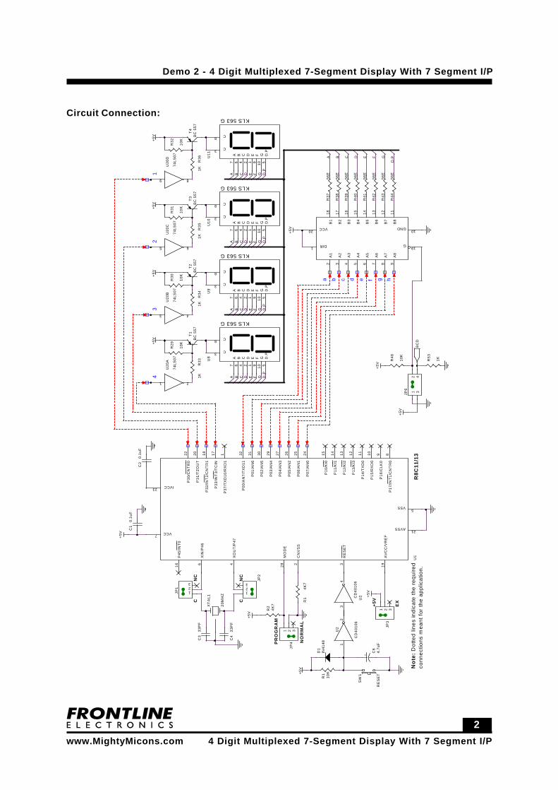
Connect P0 to the seven segments sequentially and the Port lines P30, P31, P32 and P33 to the
digit selection lines.
Page 2
2
Demo 2 - 4 Digit Multiplexed 7-Segment Display With 7 Segment I/P
www.MightyMicons.com
4 Digit Multiplexed 7-Segment Display With 7 Segment I/Pwww.MightyMicons.com
Circuit Connection:+
5V
+5V
+5V
+5V
+5V
+5V
+5V
+5V
+5V
+5V
+5V
CN
C
NC
C
PR
OG
RA
M
NO
RM
AL
+5V
EX
43
21
a b c d e f g h
GD F
C
D.P
D.P
D GFEC D.P
E
C
GFD
GD FE D.P
C E
AA
BAA B
BB
A B C D E F G
D.P
0.1u
FC
1
33P
FC
4
20M
HZ
XT
AL1
33P
FC
3
JP4
1 2 3
IN41
48D
1
CD
4010
6
U2
12
+ 4.7u
FC
6
10K
R1
T4
BC
557
R36
1K
U11
KLS 563 G
A7
B6
C4
D2
E1
F9
G10
C8
D.P
5
C3
T3
BC
557
R35
1K
U10
KLS 563 G
A7
B6
C4
D2
E1
F9
G10
C8
D.P
5
C3
U9
KLS 563 G
A7
B6
C4
D2
E1
F9
G10
C8
D.P
5
C3
R34
1K
T2
BC
557
R33
1K
T1
BC
557
U8
KLS 563 G
A7
B6
C4
D2
E1
F9
G10
C8
D.P
5
C3
R29
10K
R30
10K
R31
10K
R32
10K
U20
A
74LS
07
1 2
U20
B
74LS
07
3 4
U20
C
74LS
07
5 6
U20
D
74LS
07
9 8
JP6
12
34
R53
1K
0.1u
FC
2
CD
4010
6U
2
34
R1
4K7
JP2
123
RE
SE
T
SW
1
JP1 1
23
JP3
1 2 3R2
4K7
R48
10K
R38
56E
R43
56E
R40
56E
R42
56E
R44
56E
R41
56E
R37
56E
R39
56E
A1
2
A2
3
A3
4
A4
5
A5
6
A6
7
A7
8
A8
9
G19DIR1
B1
18
B2
17
B3
16
B4
15
B5
14
B6
13
B7
12
B8
11
VCC20GND
10
R8C
11/1
3U
1
P37
/TX
D10
/RX
D1
1
CN
VS
S2
RE
SE
T3
XO
UT
/P47
4
VSS5
XIN
/P46
6
VCC7
P17
/INT
1/C
NT
R0
8
P16
/CLK
09
P15
/RX
D0
10
P14
/TX
D0
11
P13
/KI3
12
P12
/KI2
13
P11
/KI1
14
P10
/KI0
15
P45
/INT
016
MO
DE
28
IVCC23
P30
/CN
TR
022
AVSS21
P31
/TZ
OU
T20
AV
CC
/VR
EF
19
P32
/INT
2/C
NT
R1
18
P33
/INT
3/T
CIN
17
P00
/AN
7/T
XD
1132
P01
/AN
631
P02
/AN
530
P03
/AN
429
P04
/AN
327
P05
/AN
226
P06
/AN
125
P07
/AN
024
BC
DN
ote:
Dot
ted
lines
indi
cate
the
requ
ired
conn
ectio
ns m
eant
for
the
appl
icat
ion.
Page 3
3
Demo 2 - 4 Digit Multiplexed 7-Segment Display With 7 Segment I/P
www.MightyMicons.com
4 Digit Multiplexed 7-Segment Display With 7 Segment I/Pwww.MightyMicons.com
Connections:
Port lines Display LinesP00 Segment a
P01 Segment b
P02 Segment c
P03 Segment d
P04 Segment e
P05 Segment f
P06 Segment g
P07 Segment dp
P30 Digit Selection Control for digit 1
P31 Digit Selection Control for digit 2
P32 Digit Selection Control for digit 3
P33 Digit Selection Control for digit 4
Functional Description:
In this demo, a four digit counter program is provided to study the interfacing of seven segment
display in multiplexed mode with seven segment data input. The 4 digit counter will be displayed
on the display counting from H’0000 to H’FFFF.
Registers Used:
PD0 - Port 0 Direction Register
PD3 - Port 3 Direction Register
TXMR- Timer X mode Register
PREX- Prescaler X Register
TX - Timer X Register
TCSS- Timer Count Source Setting Register
Page 4
4
Demo 2 - 4 Digit Multiplexed 7-Segment Display With 7 Segment I/P
www.MightyMicons.com
4 Digit Multiplexed 7-Segment Display With 7 Segment I/Pwww.MightyMicons.com
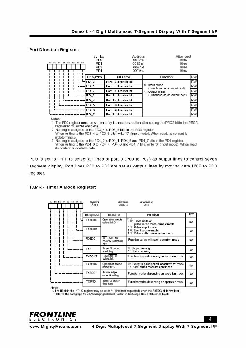
Port Direction Register:
PD0 is set to H’FF to select all lines of port 0 (P00 to P07) as output lines to control seven
segment display. Port lines P30 to P33 are set as output lines by moving data H’0F to PD3
register.
TXMR - Timer X Mode Register:
Page 5
5
Demo 2 - 4 Digit Multiplexed 7-Segment Display With 7 Segment I/P
www.MightyMicons.com
4 Digit Multiplexed 7-Segment Display With 7 Segment I/Pwww.MightyMicons.com
Timer X mode register TXMR is loaded with H’00 to set timer mode.
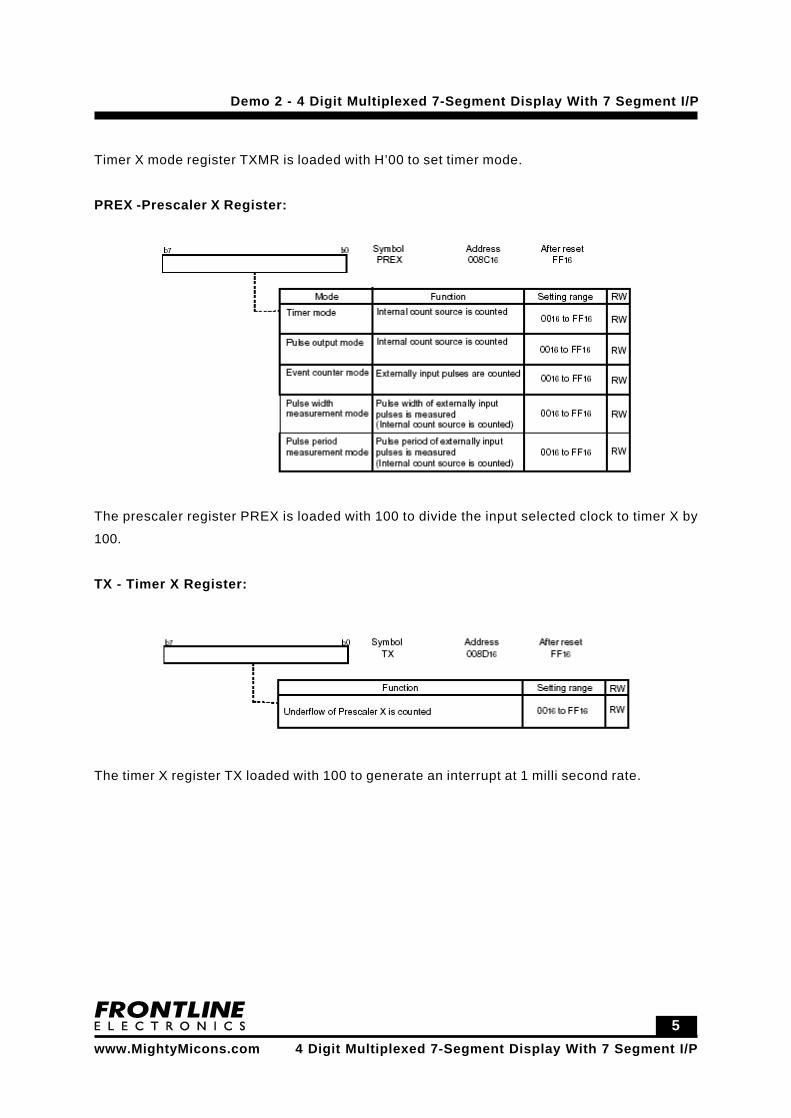
PREX -Prescaler X Register:
The prescaler register PREX is loaded with 100 to divide the input selected clock to timer X by
100.
TX - Timer X Register:
The timer X register TX loaded with 100 to generate an interrupt at 1 milli second rate.
Page 6
6
Demo 2 - 4 Digit Multiplexed 7-Segment Display With 7 Segment I/P
www.MightyMicons.com
4 Digit Multiplexed 7-Segment Display With 7 Segment I/Pwww.MightyMicons.com
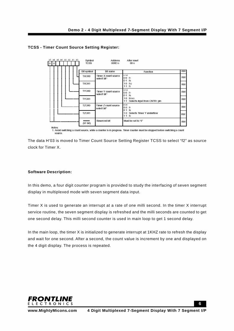
TCSS - Timer Count Source Setting Register:
The data H’03 is moved to Timer Count Source Setting Register TCSS to select “f2” as source
clock for Timer X.
Software Description:
In this demo, a four digit counter program is provided to study the interfacing of seven segment
display in multiplexed mode with seven segment data input.
Timer X is used to generate an interrupt at a rate of one milli second. In the timer X interrupt
service routine, the seven segment display is refreshed and the milli seconds are counted to get
one second delay. This milli second counter is used in main loop to get 1 second delay.
In the main loop, the timer X is initialized to generate interrupt at 1KHZ rate to refresh the display
and wait for one second. After a second, the count value is increment by one and displayed on
the 4 digit display. The process is repeated.
Page 7
7
Demo 2 - 4 Digit Multiplexed 7-Segment Display With 7 Segment I/P
www.MightyMicons.com
4 Digit Multiplexed 7-Segment Display With 7 Segment I/Pwww.MightyMicons.com
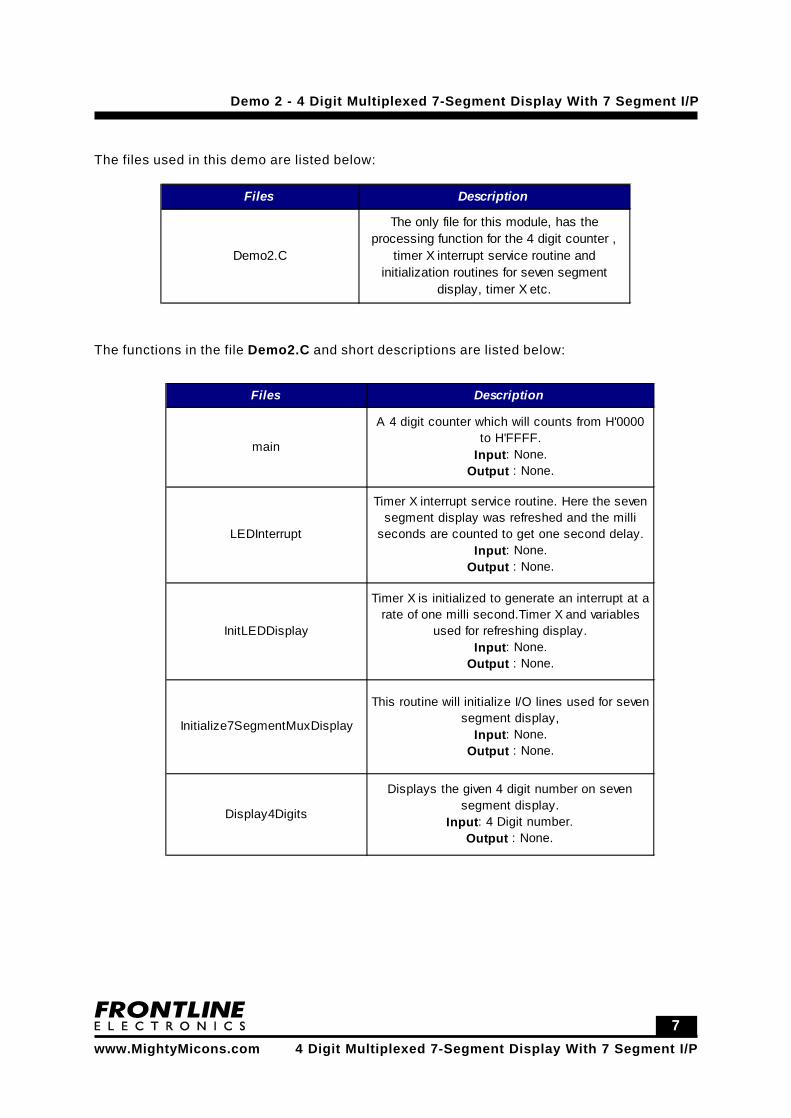
The files used in this demo are listed below:
Files Description
Demo2.C
The only file for this module, has the processing function for the 4 digit counter ,
timer X interrupt service routine and initialization routines for seven segment
display, timer X etc.
The functions in the file Demo2.C and short descriptions are listed below:
Files
Files Description
main
A 4 digit counter which will counts from H'0000 to H'FFFF.
Input: None. Output : None.
LEDInterrupt
Timer X interrupt service routine. Here the seven segment display was refreshed and the milli
seconds are counted to get one second delay. Input: None.
Output : None.
InitLEDDisplay
Timer X is initialized to generate an interrupt at a rate of one milli second.Timer X and variables
used for refreshing display. Input: None.
Output : None.
Initialize7SegmentMuxDisplay
This routine will initialize I/O lines used for seven segment display,
Input: None. Output : None.
Display4Digits
Displays the given 4 digit number on seven segment display.
Input: 4 Digit number. Output : None.
Page 8
8
Demo 2 - 4 Digit Multiplexed 7-Segment Display With 7 Segment I/P
www.MightyMicons.com
4 Digit Multiplexed 7-Segment Display With 7 Segment I/Pwww.MightyMicons.com
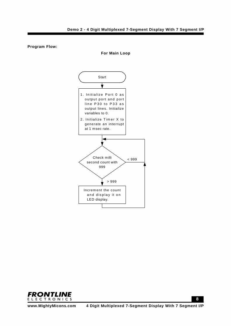
Program Flow:For Main Loop
Start
1 . I n i t i a l iz e P o r t 0 a so u tp u t p o r t a n d p o r tl i n e P 3 0 t o P 3 3 a soutput lines. In itia lizevariables to 0.
2 . In i t ia l ize T im e r X togenerate an interruptat 1 msec rate.
Check millisecond count with
999
< 999
> 999
Increm ent the counta n d d is p la y i t o nLED display.
Page 9
9
Demo 2 - 4 Digit Multiplexed 7-Segment Display With 7 Segment I/P
www.MightyMicons.com
4 Digit Multiplexed 7-Segment Display With 7 Segment I/Pwww.MightyMicons.com
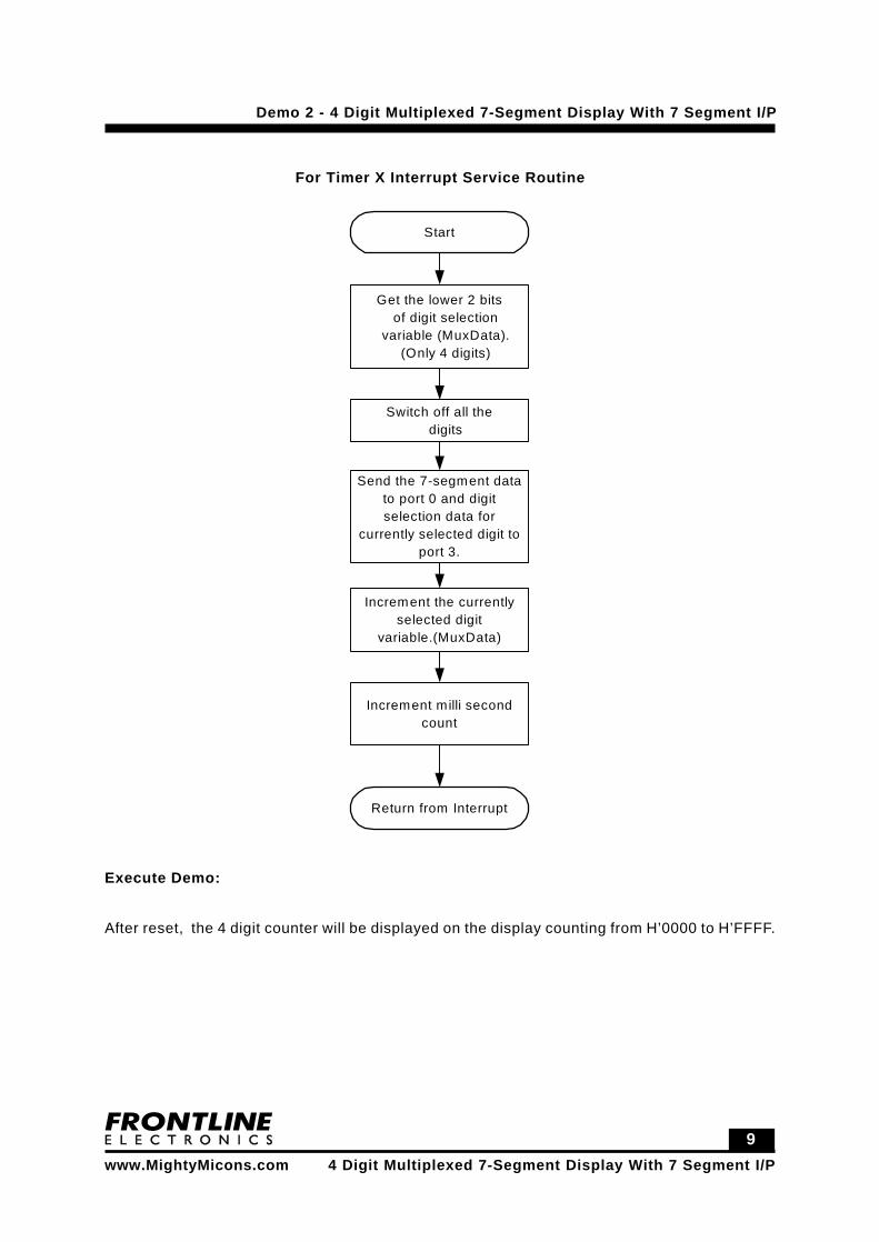
For Timer X Interrupt Service Routine
Start
Get the lower 2 bitsof digit selection
variable (MuxData).(Only 4 digits)
Switch off all thedigits
Send the 7-segment datato port 0 and digitselection data for
currently selected digit toport 3.
Increment the currentlyselected digit
variable.(MuxData)
Return from Interrupt
Increment milli secondcount
Execute Demo:
After reset, the 4 digit counter will be displayed on the display counting from H’0000 to H’FFFF.
Page 10
1 0
Demo 2 - 4 Digit Multiplexed 7-Segment Display With 7 Segment I/P
www.MightyMicons.com
4 Digit Multiplexed 7-Segment Display With 7 Segment I/Pwww.MightyMicons.com
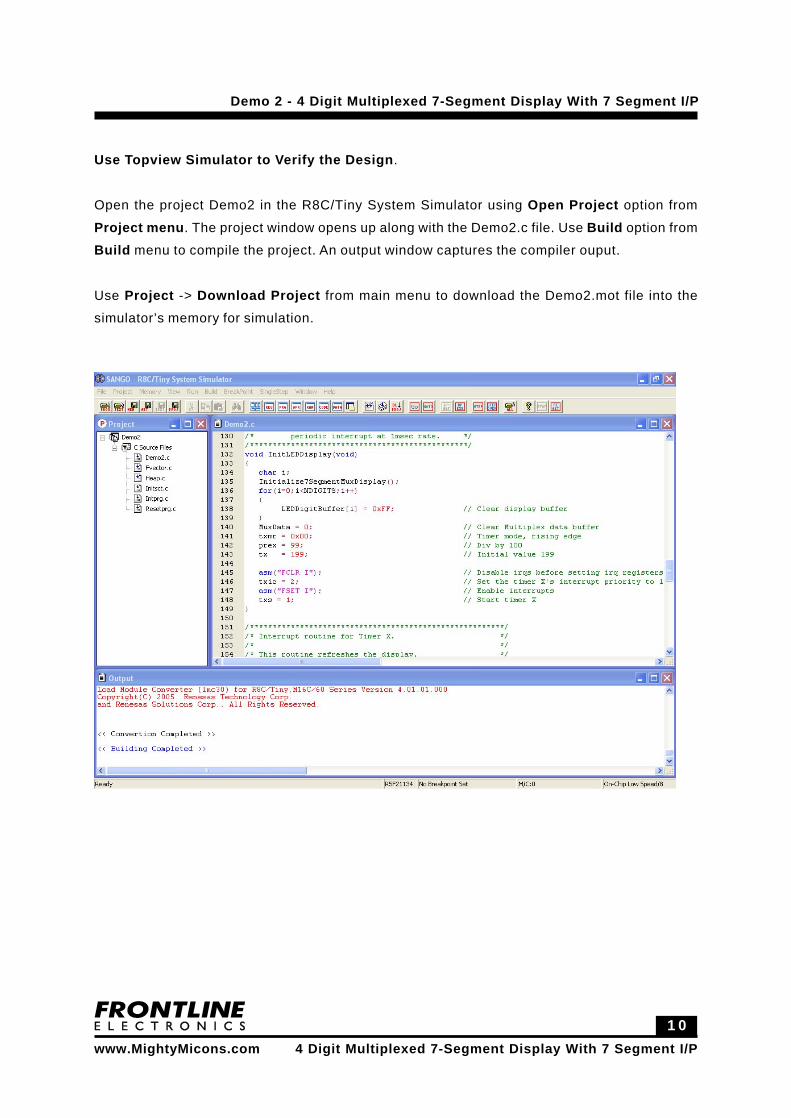
Use Topview Simulator to Verify the Design.
Open the project Demo2 in the R8C/Tiny System Simulator using Open Project option from
Project menu. The project window opens up along with the Demo2.c file. Use Build option from
Build menu to compile the project. An output window captures the compiler ouput.
Use Project -> Download Project from main menu to download the Demo2.mot file into the
simulator’s memory for simulation.
Page 11
1 1
Demo 2 - 4 Digit Multiplexed 7-Segment Display With 7 Segment I/P
www.MightyMicons.com
4 Digit Multiplexed 7-Segment Display With 7 Segment I/Pwww.MightyMicons.com
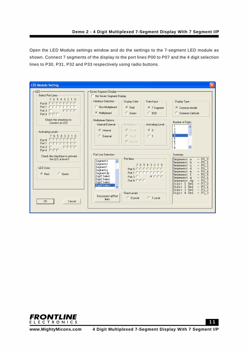
Open the LED Module settings window and do the settings to the 7-segment LED module as
shown. Connect 7 segments of the display to the port lines P00 to P07 and the 4 digit selection
lines to P30, P31, P32 and P33 respectively using radio buttons.
Page 12
1 2
Demo 2 - 4 Digit Multiplexed 7-Segment Display With 7 Segment I/P
www.MightyMicons.com
4 Digit Multiplexed 7-Segment Display With 7 Segment I/Pwww.MightyMicons.com
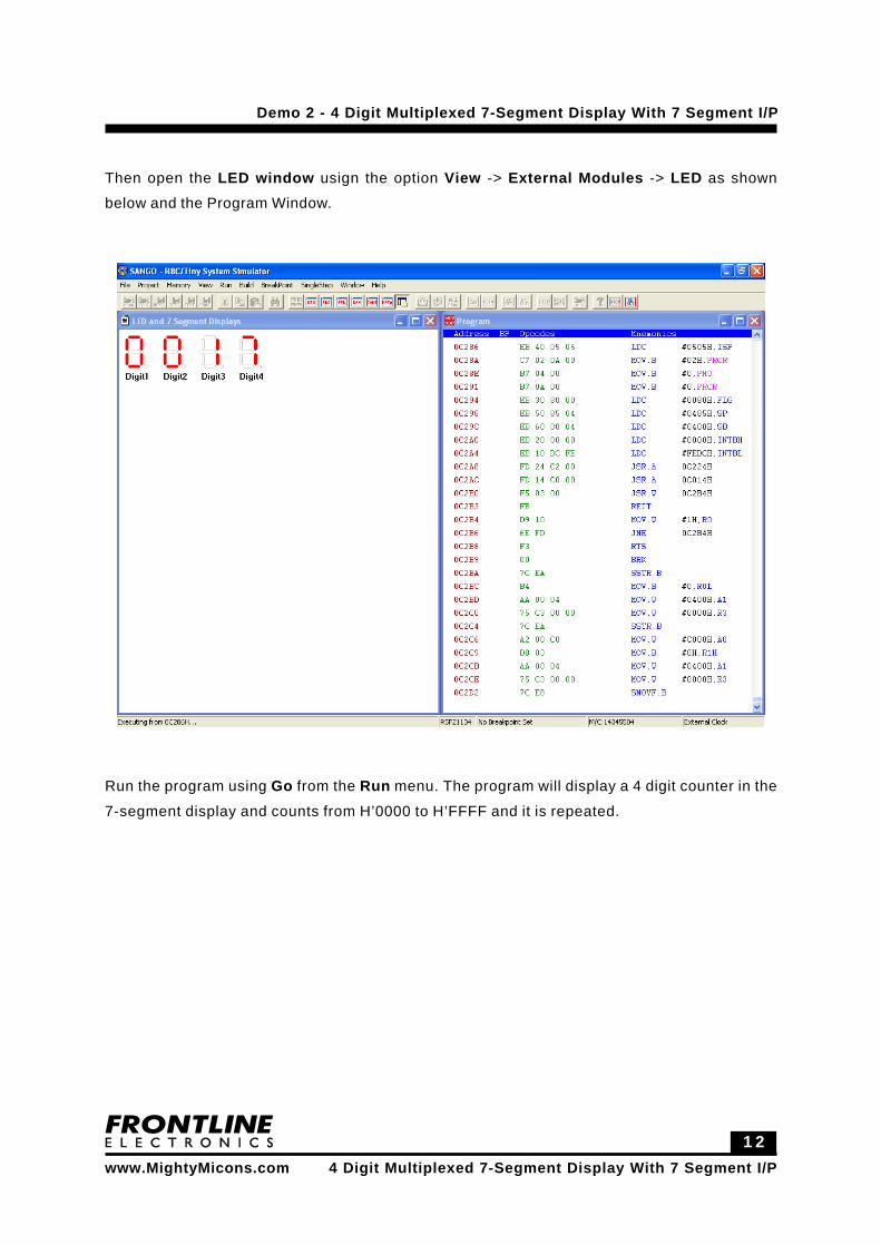
Then open the LED window usign the option View -> External Modules -> LED as shown
below and the Program Window.
Run the program using Go from the Run menu. The program will display a 4 digit counter in the
7-segment display and counts from H’0000 to H’FFFF and it is repeated.